WO2025023161A1 - 固体電解コンデンサおよび固体電解コンデンサの製造方法 - Google Patents
固体電解コンデンサおよび固体電解コンデンサの製造方法 Download PDFInfo
- Publication number
- WO2025023161A1 WO2025023161A1 PCT/JP2024/025885 JP2024025885W WO2025023161A1 WO 2025023161 A1 WO2025023161 A1 WO 2025023161A1 JP 2024025885 W JP2024025885 W JP 2024025885W WO 2025023161 A1 WO2025023161 A1 WO 2025023161A1
- Authority
- WO
- WIPO (PCT)
- Prior art keywords
- solid electrolytic
- electrolytic capacitor
- cathode
- exterior resin
- foils
- Prior art date
- Legal status (The legal status is an assumption and is not a legal conclusion. Google has not performed a legal analysis and makes no representation as to the accuracy of the status listed.)
- Pending
Links
Images

Classifications
-
- H—ELECTRICITY
- H01—ELECTRIC ELEMENTS
- H01G—CAPACITORS; CAPACITORS, RECTIFIERS, DETECTORS, SWITCHING DEVICES, LIGHT-SENSITIVE OR TEMPERATURE-SENSITIVE DEVICES OF THE ELECTROLYTIC TYPE
- H01G9/00—Electrolytic capacitors, rectifiers, detectors, switching devices, light-sensitive or temperature-sensitive devices; Processes of their manufacture
-
- H—ELECTRICITY
- H01—ELECTRIC ELEMENTS
- H01G—CAPACITORS; CAPACITORS, RECTIFIERS, DETECTORS, SWITCHING DEVICES, LIGHT-SENSITIVE OR TEMPERATURE-SENSITIVE DEVICES OF THE ELECTROLYTIC TYPE
- H01G9/00—Electrolytic capacitors, rectifiers, detectors, switching devices, light-sensitive or temperature-sensitive devices; Processes of their manufacture
- H01G9/004—Details
- H01G9/008—Terminals
- H01G9/012—Terminals specially adapted for solid capacitors
-
- H—ELECTRICITY
- H01—ELECTRIC ELEMENTS
- H01G—CAPACITORS; CAPACITORS, RECTIFIERS, DETECTORS, SWITCHING DEVICES, LIGHT-SENSITIVE OR TEMPERATURE-SENSITIVE DEVICES OF THE ELECTROLYTIC TYPE
- H01G9/00—Electrolytic capacitors, rectifiers, detectors, switching devices, light-sensitive or temperature-sensitive devices; Processes of their manufacture
- H01G9/004—Details
- H01G9/04—Electrodes or formation of dielectric layers thereon
- H01G9/048—Electrodes or formation of dielectric layers thereon characterised by their structure
-
- H—ELECTRICITY
- H01—ELECTRIC ELEMENTS
- H01G—CAPACITORS; CAPACITORS, RECTIFIERS, DETECTORS, SWITCHING DEVICES, LIGHT-SENSITIVE OR TEMPERATURE-SENSITIVE DEVICES OF THE ELECTROLYTIC TYPE
- H01G9/00—Electrolytic capacitors, rectifiers, detectors, switching devices, light-sensitive or temperature-sensitive devices; Processes of their manufacture
- H01G9/004—Details
- H01G9/04—Electrodes or formation of dielectric layers thereon
- H01G9/06—Mounting in containers
-
- H—ELECTRICITY
- H01—ELECTRIC ELEMENTS
- H01G—CAPACITORS; CAPACITORS, RECTIFIERS, DETECTORS, SWITCHING DEVICES, LIGHT-SENSITIVE OR TEMPERATURE-SENSITIVE DEVICES OF THE ELECTROLYTIC TYPE
- H01G9/00—Electrolytic capacitors, rectifiers, detectors, switching devices, light-sensitive or temperature-sensitive devices; Processes of their manufacture
- H01G9/004—Details
- H01G9/08—Housing; Encapsulation
-
- H—ELECTRICITY
- H01—ELECTRIC ELEMENTS
- H01G—CAPACITORS; CAPACITORS, RECTIFIERS, DETECTORS, SWITCHING DEVICES, LIGHT-SENSITIVE OR TEMPERATURE-SENSITIVE DEVICES OF THE ELECTROLYTIC TYPE
- H01G9/00—Electrolytic capacitors, rectifiers, detectors, switching devices, light-sensitive or temperature-sensitive devices; Processes of their manufacture
- H01G9/15—Solid electrolytic capacitors
Definitions
- This disclosure relates to a solid electrolytic capacitor and a method for manufacturing a solid electrolytic capacitor.
- the solid electrolytic capacitor of Patent Document 1 includes a laminate in which multiple capacitor elements, each having an anode foil, and multiple cathode foils are stacked, and an exterior resin that covers the laminate.
- the exterior resin has a first end surface on which a portion of each anode foil is exposed, and a second end surface on which a portion of each cathode foil is exposed.
- the solid electrolytic capacitor further includes an anode terminal electrically connected to each anode foil at the first end surface, and a cathode terminal electrically connected to each cathode foil at the second end surface.
- the solid electrolytic capacitor of Patent Document 1 is proposed as having a low equivalent series resistance (ESR), but the ESR is not sufficiently low. In this situation, one of the objectives of this disclosure is to reduce the ESR.
- ESR equivalent series resistance
- the solid electrolytic capacitor includes a laminate in which a plurality of capacitor elements, each having an anode foil, and a plurality of cathode foils are laminated, an exterior resin covering the laminate and having a first end face at which a portion of each of the anode foils is exposed and a second end face at which a portion of each of the cathode foils is exposed, an anode external electrode electrically connected to each of the anode foils at the first end face, and a cathode external electrode electrically connected to each of the cathode foils at the second end face, and a first average distance from the first end point on the second end face to each of the cathode foils in the lamination direction of the laminate, with an end point on the mounting surface side of the exterior resin on the second end face being a first end point, is smaller than a second average distance from the first end point to each of the cathode foils in a region where the capacitor elements
- the method is a method for manufacturing the above-mentioned solid electrolytic capacitor, and includes a preparation step of preparing the laminate, and a molding step of forming the exterior resin using a compression molding method in which a resin material is supplied to the laminate from the side opposite the mounting surface.
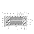
- FIG. 1 is a cross-sectional view illustrating a schematic diagram of an example of a solid electrolytic capacitor according to the present disclosure.
- 3A is a cross-sectional view of a solid electrolytic capacitor taken along line A-A in FIG. 1, showing a second end face;
- FIG. 3B is a cross-sectional view taken along line B-B in FIG. 1, with the capacitor element omitted;
- FIG. 3C is a cross-sectional view taken along line CC in FIG. 1, showing a first end face.
- the solid electrolytic capacitor according to the present disclosure is a so-called end-collection type solid electrolytic capacitor, and includes a laminate, an exterior resin, an anode external electrode, and a cathode external electrode.
- the laminate is made up of multiple capacitor elements and multiple cathode foils stacked together.
- Each of the multiple capacitor elements has an anode foil.
- Each cathode foil may be thinner than each anode foil.
- the anode foil may be made of a valve metal such as aluminum, tantalum, niobium, or titanium, or an alloy or compound containing these valve metals.
- the surface of the anode foil may be roughened by etching or the like.
- At least a portion of the surface of the anode foil is provided with a dielectric layer (e.g., a layer of an oxide of the valve metal), and at least a portion of the dielectric layer is covered with a solid electrolyte layer. At least a portion of the solid electrolyte layer may be covered with a conductive layer.
- the dielectric layer may be composed of an oxide (e.g., aluminum oxide) formed on the surface of the anode foil by a liquid phase method such as anodization, or a gas phase method such as vapor deposition or atomic layer deposition.
- an oxide e.g., aluminum oxide
- a liquid phase method such as anodization
- a gas phase method such as vapor deposition or atomic layer deposition.
- the solid electrolyte layer may include a conductive polymer. If necessary, the solid electrolyte layer may further include a dopant.
- the conductive polymer may be a known one used in solid electrolytic capacitors, such as a ⁇ -conjugated conductive polymer.
- the conductive polymer include polymers having a basic skeleton of polypyrrole, polythiophene, polyaniline, polyfuran, polyacetylene, polyphenylene, polyphenylenevinylene, polyacene, and polythiophenevinylene. Of these, polymers having a basic skeleton of polypyrrole, polythiophene, or polyaniline are preferred.
- the above polymers include homopolymers, copolymers of two or more monomers, and derivatives thereof (such as substituted products having a substituent).
- polythiophenes include poly(3,4-ethylenedioxythiophene).
- the conductive polymers may be used alone or in combination of two or more.
- the dopant is, for example, at least one selected from the group consisting of low molecular weight anions and polyanions.
- low molecular weight anions include, but are not limited to, sulfate ions, nitrate ions, phosphate ions, borate ions, organic sulfonate ions, and carboxylate ions.
- dopants that generate organic sulfonate ions include, for example, benzenesulfonic acid, p-toluenesulfonic acid, and naphthalenesulfonic acid.
- polyanions include, for example, polymer-type polysulfonic acids and polymer-type polycarboxylic acids.
- polymer-type polysulfonic acids examples include polyvinylsulfonic acid, polystyrenesulfonic acid, polyallylsulfonic acid, polyacrylicsulfonic acid, and polymethacrylicsulfonic acid.
- polymer-type polycarboxylic acids examples include polyacrylic acid and polymethacrylic acid.
- polyanions include polyestersulfonic acid and phenolsulfonic acid novolac resin. However, the polyanions are not limited to these.
- the solid electrolyte layer may further contain known additives and known conductive materials other than conductive polymers, as necessary.
- conductive materials include at least one selected from the group consisting of conductive inorganic materials such as manganese dioxide and TCNQ complex salts.
- the conductive layer may be composed of only a carbon layer formed on the surface of the solid electrolyte layer, or may be composed of a carbon layer and a conductive layer formed on the surface of the carbon layer.
- the conductive layer may be composed of silver paste.
- As the silver paste for example, a composition containing silver particles and a resin component (binder resin) may be used.
- a resin component a thermoplastic resin may be used, but it is preferable to use a thermosetting resin such as an imide resin or an epoxy resin.
- the cathode foil may be made of a metal such as gold, silver, copper, aluminum, or nickel.
- the surface of the cathode foil may be roughened by etching or the like, and may further be coated with carbon or the like.
- the cathode foil may be connected to the conductive layer, for example, via a conductive adhesive.
- the conductivity of the material constituting the cathode foil may be higher than the conductivity of the material constituting the cathode external electrode.
- the exterior resin covers the laminate.
- the exterior resin has a first end face where a portion of each anode foil is exposed, and a second end face where a portion of each cathode foil is exposed.
- the first end face and the second end face may face in opposite directions.
- the shapes of the first end face and the second end face are not particularly limited, and may be flat or curved, or may have at least a portion of unevenness.
- the exterior resin may be made of an insulating resin material.
- the exterior resin may be a cured product of a thermosetting resin containing, for example, an epoxy resin, and may contain a filler as necessary.
- the anode external electrode is electrically connected to each anode foil at the first end surface of the exterior resin.
- the anode external electrode may be made of silver, copper, a copper alloy, aluminum, or an aluminum alloy, and may be plated.
- a plating layer, a conductive adhesive, or the like may or may not be interposed between the anode external electrode and each anode foil.
- the anode external electrode may have a single-layer structure or a multi-layer structure.
- the multi-layer anode external electrode may have, for example, at least one metal layer and at least one plating layer. A portion of the anode external electrode may extend along the mounting surface of the exterior resin (the mounting surface of the solid electrolytic capacitor).
- the cathode external electrode is electrically connected to each cathode foil at the second end surface of the exterior resin.
- the cathode external electrode may be made of silver, copper, a copper alloy, aluminum, or an aluminum alloy, and may be plated.
- the constituent material of the cathode external electrode may be the same as or different from the constituent material of the anode external electrode.
- a plating layer, a conductive adhesive, or the like may or may not be interposed between the cathode external electrode and each cathode foil.
- the cathode external electrode may have a single layer structure or a multi-layer structure.
- the multi-layer cathode external electrode may have, for example, at least one metal layer and at least one plating layer.
- a portion of the cathode external electrode may extend along the mounting surface of the exterior resin (the mounting surface of the solid electrolytic capacitor).
- the first end point is the end point of the second end face of the exterior resin on the mounting surface side of the exterior resin.
- a first average distance from the first end point on the second end face to each cathode foil is smaller than a second average distance from the first end point to each cathode foil in a region where the capacitor element and the cathode foil overlap (e.g., a region including a midpoint between the first end face and the second end face; hereinafter, also referred to as an overlapping region).
- the average distance from the first end point to each cathode foil in the stacking direction refers to the sum of the shortest distances from the first end point to each cathode foil in the stacking direction divided by the number of cathode foils provided in the solid electrolytic capacitor.
- the first average distance at the second end face is smaller than the second average distance in the overlapping region.
- the multiple cathode foils are arranged closer to the mounting surface as a whole. Therefore, when the solid electrolytic capacitor according to the present disclosure is mounted on a substrate or the like, the total current path from the wiring of the substrate to each cathode foil is shorter than when, for example, the solid electrolytic capacitor of Patent Document 1 is mounted on a substrate or the like. Therefore, the ESR of the solid electrolytic capacitor can be reduced.
- the first average distance is preferably 90% or less of the second average distance, and more preferably 80% or less of the second average distance.
- At least one pair of cathode foils may be present on the second end surface, adjacent to each other in the stacking direction and spaced apart from each other.
- Such at least one pair of cathode foils may be present on the mounting surface side of a plurality of cathode foils. For example, when eight cathode foils are present, three or more and five or less cathode foils on the mounting surface side may be spaced apart from each other.
- At least one pair of anode foils may be present on the first end surface, adjacent to each other in the stacking direction and spaced apart from each other. Such at least one pair of anode foils may be present on the mounting surface side of the multiple anode foils.
- the ratio of the number of spaced anode foils to the total number of anode foils may be higher than the ratio of the number of spaced cathode foils to the total number of cathode foils. For example, when there are seven anode foils, five or more and seven or less anode foils on the mounting surface side may be spaced apart from each other. With this configuration, it is possible to prevent damage to the anode foils due to excessive force acting on the anode foils when the laminate is covered with an exterior resin.
- the exterior resin may contain a filler.
- the filler content in the exterior resin may be 85% by weight or more and 95% by weight or less.
- the flexural modulus of the exterior resin at 25°C may be 20 GPa or more. This configuration makes it possible to realize physical properties of the exterior resin that are particularly suitable for realizing the structure of the solid electrolytic capacitor according to the present disclosure.
- the glass transition temperature of the exterior resin may be 135°C or higher. This configuration makes it possible to realize physical properties of the exterior resin that are particularly suitable for realizing the structure of the solid electrolytic capacitor according to the present disclosure.
- a method for producing a solid electrolytic capacitor according to the present disclosure is a method for producing the above-mentioned solid electrolytic capacitor, and includes a preparation step and a molding step.
- the laminate is prepared.
- the laminate may be prepared by alternately stacking a plurality of anode foils and a plurality of cathode foils.
- the exterior resin is formed by using a compression molding method so that the resin material is supplied to the laminate from the side opposite the mounting surface.
- the compression molding method for example, after granular resin material is placed in a mold, the resin material is melted and pressure is applied to fill and form the exterior resin in the process of closing the heated mold. Since the resin material is supplied to the laminate from the side opposite the mounting surface, pressure acts on the laminate to press it towards the mounting surface. This pressure presses the area of at least one cathode foil near the second end face towards the mounting surface and deforms it, so that the first average distance becomes smaller than the second average distance, and thus a solid electrolytic capacitor with a low ESR is obtained.
- the exterior resin may contain a filler.
- the content of the filler in the exterior resin may be 85% by weight or more and 95% by weight or less.
- the flexural modulus of the exterior resin at 25°C may be 20 GPa or more. With this configuration, it is possible to realize properties of the exterior resin that are particularly suitable for realizing the structure of the solid electrolytic capacitor according to the present disclosure by the above-mentioned compression molding method.
- the glass transition temperature of the exterior resin may be 135°C or higher.
- the ESR of the solid electrolytic capacitor can be reduced by making the first average distance at the second end face smaller than the second average distance in the overlap region.
- the solid electrolytic capacitor 10 of this embodiment is a so-called end-collection type solid electrolytic capacitor, and includes a laminate 20, an exterior resin 30, an anode external electrode 40, and a cathode external electrode 50, as shown in FIGS.
- the laminate 20 is made up of multiple (three in this example) capacitor elements 21 and multiple (four in this example) cathode foils 26 stacked alternately. Each of the multiple capacitor elements 21 has an anode foil 22.
- the anode foil 22 in this embodiment is formed in a rectangular sheet shape, and its surface is roughened.
- a dielectric layer 23 is formed on at least a portion of the surface of the anode foil 22, and at least a portion of the dielectric layer 23 is covered with a solid electrolyte layer 24. At least a portion of the solid electrolyte layer 24 is covered with a conductive layer 25.
- the cathode foil 26 in this embodiment is formed in a rectangular sheet shape, and its surface is roughened.
- the cathode foil 26 is electrically connected to the conductive layer 25 of the anode foil 22 via a conductive adhesive (not shown).
- the cathode foil 26 is made of a material that has a higher conductivity than the material that constitutes the cathode external electrode 50.
- the exterior resin 30 covers the laminate 20.
- the exterior resin 30 has a first end surface 31 (the end surface on the right side in FIG. 1 ) where a portion of each anode foil 22 is exposed, and a second end surface 32 (the end surface on the left side in FIG. 1 ) where a portion of each cathode foil 26 is exposed.
- the exterior resin 30 is made of an insulating resin material.
- the exterior resin 30 contains a filler (not shown) at a content of 85% by weight or more and 95% by weight or less.
- the flexural modulus of the exterior resin 30 at 25° C. is 20 GPa or more, and may be, for example, 20 GPa or more and 35 GPa or less.
- the glass transition temperature of the exterior resin 30 is 135° C. or more, and may be, for example, 135° C. or more and 160° C. or less.
- the anode external electrode 40 is electrically connected to each anode foil 22 at the first end surface 31 of the exterior resin 30.
- the anode external electrode 40 is electrically connected to each anode foil 22 via a conductive adhesive 60, but is not limited to this.
- the anode external electrode 40 has a first portion 41 that extends along the first end surface 31, and a second portion 42 that is continuous with the first portion 41 and extends along the mounting surface 33 (the bottom surface in FIG. 1) of the exterior resin 30.
- the cathode external electrode 50 is electrically connected to each cathode foil 26 at the second end surface 32 of the exterior resin 30.
- the cathode external electrode 50 is electrically connected to each cathode foil 26 via a conductive adhesive 60, but is not limited to this.
- the cathode external electrode 50 has a third portion 51 extending along the second end surface 32, and a fourth portion 52 that is continuous with the third portion 51 and extends along the mounting surface 33 of the exterior resin 30.
- the end point of the second end face 32 of the exterior resin 30 on the mounting surface 33 side of the exterior resin 30 is defined as the first end point P1.
- the first average distance AD1 from the first end point P1 on the second end face 32 to each cathode foil 26 is smaller than the second average distance AD2 from the first end point P1 to each cathode foil 26 in the overlapping region R1, which is the region where the capacitor element 21 and the cathode foil 26 overlap.
- This relationship in magnitude between the first average distance AD1 and the second average distance AD2 is due to the fact that, as shown in FIG. 1, at least a portion of the cathode foils 26 are shaped to face the mounting surface 33 as they move from the overlapping region R1 toward the second end face 32.
- first end point P1 is shown in FIG. 2 (b), but this is the first end point P1 projected onto the cross-sectional position in the figure in the opposing direction between the first end face 31 and the second end face 32 (left and right direction in FIG. 1).
- At least one pair of cathode foils 26 are adjacent to each other and spaced apart from each other in the stacking direction LD on the second end surface 32. In this example, this corresponds to the pair of cathode foils 26 on the mounting surface 33 side. Also, as shown in FIG. 2(c), at least one pair of anode foils 22 are adjacent to each other and spaced apart from each other in the stacking direction LD on the first end surface 31. In this example, all of the cathode foils 26 correspond to this.
- the method for manufacturing the solid electrolytic capacitor of the present embodiment is a method for manufacturing the above-described solid electrolytic capacitor 10, and includes a preparation step and a molding step.
- the laminate 20 described above is prepared.
- the laminate 20 is prepared by alternately stacking a plurality of anode foils 22 and a plurality of cathode foils 26.
- the exterior resin 30 is formed by using a compression molding method so that the resin material is supplied to the laminate 20 from the side opposite the mounting surface 33 (the upper side in FIG. 1).
- the molten resin material is supplied in a specified mold, so the laminate 20 is subjected to the molding process in an orientation upside down from that shown in FIG. 1.
- a laminate including a plurality of capacitor elements each having an anode foil and a plurality of cathode foils; an exterior resin covering the laminate and having a first end surface from which a portion of each of the anode foils is exposed and a second end surface from which a portion of each of the cathode foils is exposed; an anode external electrode electrically connected to each of the anode foils at the first end surface; a cathode external electrode electrically connected to each of the cathode foils at the second end surface; Equipped with a first average distance from an end point of the second end face on a mounting surface side of the exterior resin to each of the cathode foils in a stacking direction of the laminate is smaller than a second average distance from the first end point to each of the cathode foils in a region where the capacitor element and the cathode foil overlap.
- (Technique 7) A method for producing the solid electrolytic capacitor according to any one of Techniques 1 to 6, comprising the steps of: A preparation step of preparing the laminate; a molding process of forming the exterior resin by using a compression molding method so as to supply a resin material to the laminate from the opposite side to the mounting surface; A method for manufacturing a solid electrolytic capacitor comprising the steps of: (Technique 8)
- the exterior resin contains a filler, 8.
- the method for producing a solid electrolytic capacitor according to claim 7, wherein the content of the filler in the exterior resin is 85% by weight or more and 95% by weight or less.
- (Technique 9) 9.
- (Technique 10) 10. The method for producing a solid electrolytic capacitor according to any one of claims 7 to 9, wherein the exterior resin has a glass transition temperature of 135° C. or higher.
- Example 1 A laminate was formed by alternately stacking seven capacitor elements and eight cathode foils. The laminate was covered with an exterior resin. A portion of each anode foil was exposed from a first end surface of the exterior resin. All the anode foils were spaced apart from each other at the first end surface. An anode external electrode was electrically connected to each anode foil at the first end surface. A portion of each cathode foil was exposed from a second end surface of the exterior resin. At the second end surface, the four cathode foils on the mounting surface side were spaced apart from each other, while the remaining four cathode foils were in contact with each other. At the second end surface, a cathode external electrode was electrically connected to each cathode foil. The first average distance at the second end surface was 76% of the second average distance at the overlapping region. The ESR of the solid electrolytic capacitor of Example 1 was 90% of the ESR of the solid electrolytic capacitor of Comparative Example 1.
- Example 2 A laminate was formed by alternately stacking seven capacitor elements and eight cathode foils. The laminate was covered with an exterior resin. A portion of each anode foil was exposed from a first end face of the exterior resin. All the anode foils were spaced apart from each other at the first end face. An anode external electrode was electrically connected to each anode foil at the first end face. A portion of each cathode foil was exposed from a second end face of the exterior resin. All the cathode foils were in contact with each other on the mounting surface side at the second end face. A cathode external electrode was electrically connected to each cathode foil at the second end face. The first average distance at the second end face was 33% of the second average distance in the overlapping region. The ESR of the solid electrolytic capacitor of Example 2 was 78% of the ESR of the solid electrolytic capacitor of Comparative Example 1.
- Comparative Example 1 A laminate was formed by alternately stacking seven capacitor elements and eight cathode foils. The laminate was covered with an exterior resin. A portion of each anode foil was exposed from a first end face of the exterior resin. All the anode foils were spaced apart from one another at the first end face. An anode external electrode was electrically connected to each anode foil at the first end face. A portion of each cathode foil was exposed from a second end face of the exterior resin. All the cathode foils were spaced apart from one another at the second end face. A cathode external electrode was electrically connected to each cathode foil at the second end face. The anode foils and cathode foils of Comparative Example 1 extend in parallel throughout. That is, in the solid electrolytic capacitor of Comparative Example 1, the first average distance and the second average distance are equal to each other.
- Comparative Example 2 A laminate was formed by alternately stacking seven capacitor elements and eight cathode foils. The laminate was covered with an exterior resin. A portion of each anode foil was exposed from a first end surface of the exterior resin. All the anode foils were spaced apart from each other at the first end surface. An anode external electrode was electrically connected to each anode foil at the first end surface. A portion of each cathode foil was exposed from a second end surface of the exterior resin. All the cathode foils were in contact with each other at the second end surface on the side opposite to the mounting surface. A cathode external electrode was electrically connected to each cathode foil at the second end surface. The first average distance at the second end surface was 167% of the second average distance in the overlapping region. The ESR of the solid electrolytic capacitor of Comparative Example 2 was 152% of the ESR of the solid electrolytic capacitor of Comparative Example 1.
- the solid electrolytic capacitors of Comparative Examples 1 and 2 had a lower ESR than the solid electrolytic capacitors of Comparative Examples 1 and 2. Therefore, it can be said that the superiority of each example was demonstrated.
- This disclosure can be used for solid electrolytic capacitors and methods for manufacturing solid electrolytic capacitors.
Landscapes
- Engineering & Computer Science (AREA)
- Power Engineering (AREA)
- Microelectronics & Electronic Packaging (AREA)
- Fixed Capacitors And Capacitor Manufacturing Machines (AREA)
Priority Applications (2)
| Application Number | Priority Date | Filing Date | Title |
|---|---|---|---|
| CN202480048380.8A CN121548871A (zh) | 2023-07-26 | 2024-07-19 | 固体电解电容器和固体电解电容器的制造方法 |
| JP2025535785A JPWO2025023161A1 (https=) | 2023-07-26 | 2024-07-19 |
Applications Claiming Priority (2)
| Application Number | Priority Date | Filing Date | Title |
|---|---|---|---|
| JP2023-121571 | 2023-07-26 | ||
| JP2023121571 | 2023-07-26 |
Publications (1)
| Publication Number | Publication Date |
|---|---|
| WO2025023161A1 true WO2025023161A1 (ja) | 2025-01-30 |
Family
ID=94374592
Family Applications (1)
| Application Number | Title | Priority Date | Filing Date |
|---|---|---|---|
| PCT/JP2024/025885 Pending WO2025023161A1 (ja) | 2023-07-26 | 2024-07-19 | 固体電解コンデンサおよび固体電解コンデンサの製造方法 |
Country Status (3)
| Country | Link |
|---|---|
| JP (1) | JPWO2025023161A1 (https=) |
| CN (1) | CN121548871A (https=) |
| WO (1) | WO2025023161A1 (https=) |
Citations (6)
| Publication number | Priority date | Publication date | Assignee | Title |
|---|---|---|---|---|
| JP2003086459A (ja) * | 2001-07-02 | 2003-03-20 | Matsushita Electric Ind Co Ltd | 固体電解コンデンサ |
| WO2006077906A1 (ja) * | 2005-01-24 | 2006-07-27 | Matsushita Electric Industrial Co., Ltd. | チップ型固体電解コンデンサ |
| JP2011003827A (ja) * | 2009-06-22 | 2011-01-06 | Panasonic Corp | 電子部品 |
| JP2011176219A (ja) * | 2010-02-25 | 2011-09-08 | Nichicon Corp | 固体電解コンデンサおよびその製造方法 |
| WO2021049056A1 (ja) * | 2019-09-11 | 2021-03-18 | 株式会社村田製作所 | 電解コンデンサ |
| WO2022163645A1 (ja) * | 2021-01-29 | 2022-08-04 | パナソニックIpマネジメント株式会社 | 電解コンデンサ |
-
2024
- 2024-07-19 WO PCT/JP2024/025885 patent/WO2025023161A1/ja active Pending
- 2024-07-19 CN CN202480048380.8A patent/CN121548871A/zh active Pending
- 2024-07-19 JP JP2025535785A patent/JPWO2025023161A1/ja active Pending
Patent Citations (6)
| Publication number | Priority date | Publication date | Assignee | Title |
|---|---|---|---|---|
| JP2003086459A (ja) * | 2001-07-02 | 2003-03-20 | Matsushita Electric Ind Co Ltd | 固体電解コンデンサ |
| WO2006077906A1 (ja) * | 2005-01-24 | 2006-07-27 | Matsushita Electric Industrial Co., Ltd. | チップ型固体電解コンデンサ |
| JP2011003827A (ja) * | 2009-06-22 | 2011-01-06 | Panasonic Corp | 電子部品 |
| JP2011176219A (ja) * | 2010-02-25 | 2011-09-08 | Nichicon Corp | 固体電解コンデンサおよびその製造方法 |
| WO2021049056A1 (ja) * | 2019-09-11 | 2021-03-18 | 株式会社村田製作所 | 電解コンデンサ |
| WO2022163645A1 (ja) * | 2021-01-29 | 2022-08-04 | パナソニックIpマネジメント株式会社 | 電解コンデンサ |
Also Published As
| Publication number | Publication date |
|---|---|
| CN121548871A (zh) | 2026-02-17 |
| JPWO2025023161A1 (https=) | 2025-01-30 |
Similar Documents
| Publication | Publication Date | Title |
|---|---|---|
| US11875950B2 (en) | Electrolytic capacitor | |
| US7916457B2 (en) | Multi-layered solid electrolytic capacitor and method of manufacturing same | |
| WO2022059459A1 (ja) | 固体電解コンデンサ | |
| US20250046526A1 (en) | Electrolytic capacitor | |
| WO2022163645A1 (ja) | 電解コンデンサ | |
| US12354812B2 (en) | Solid electrolytic capacitor element and solid electrolytic capacitor | |
| US12368005B2 (en) | Solid electrolytic capacitor element and solid electrolytic capacitor | |
| US8559165B2 (en) | Solid electrolytic capacitor | |
| JP7706065B2 (ja) | 電解コンデンサ | |
| WO2022270195A1 (ja) | 固体電解コンデンサ | |
| WO2025023161A1 (ja) | 固体電解コンデンサおよび固体電解コンデンサの製造方法 | |
| JP2004087713A (ja) | アルミニウム固体電解コンデンサ | |
| JP2024142925A (ja) | 固体電解コンデンサ | |
| JP4899758B2 (ja) | 固体電解コンデンサ用リードフレーム部材 | |
| JP4899759B2 (ja) | 固体電解コンデンサ用リードフレーム部材 | |
| JP7200912B2 (ja) | 電解コンデンサ | |
| JP7727956B2 (ja) | 固体電解コンデンサ | |
| US20250322994A1 (en) | Solid electrolytic capacitor and method for manufacturing solid electrolytic capacitor | |
| US20250329503A1 (en) | Solid electrolytic capacitor | |
| US20250149257A1 (en) | Solid electrolytic capacitor | |
| WO2025154713A1 (ja) | 積層コンデンサ | |
| WO2025169887A1 (ja) | 固体電解コンデンサ | |
| WO2025263574A1 (ja) | 固体電解コンデンサおよび固体電解コンデンサの製造方法 | |
| WO2025263573A1 (ja) | 固体電解コンデンサおよび固体電解コンデンサの製造方法 | |
| WO2024057931A1 (ja) | 有機導電体用の添加剤 |
Legal Events
| Date | Code | Title | Description |
|---|---|---|---|
| 121 | Ep: the epo has been informed by wipo that ep was designated in this application |
Ref document number: 24845538 Country of ref document: EP Kind code of ref document: A1 |
|
| ENP | Entry into the national phase |
Ref document number: 2025535785 Country of ref document: JP Kind code of ref document: A |
|
| WWE | Wipo information: entry into national phase |
Ref document number: 2025535785 Country of ref document: JP |
|
| NENP | Non-entry into the national phase |
Ref country code: DE |