WO2025023063A1 - クロストーク測定装置、及びクロストーク測定方法 - Google Patents
クロストーク測定装置、及びクロストーク測定方法 Download PDFInfo
- Publication number
- WO2025023063A1 WO2025023063A1 PCT/JP2024/025228 JP2024025228W WO2025023063A1 WO 2025023063 A1 WO2025023063 A1 WO 2025023063A1 JP 2024025228 W JP2024025228 W JP 2024025228W WO 2025023063 A1 WO2025023063 A1 WO 2025023063A1
- Authority
- WO
- WIPO (PCT)
- Prior art keywords
- optical waveguide
- light
- crosstalk
- core
- port
- Prior art date
- Legal status (The legal status is an assumption and is not a legal conclusion. Google has not performed a legal analysis and makes no representation as to the accuracy of the status listed.)
- Pending
Links
Images




Classifications
-
- G—PHYSICS
- G01—MEASURING; TESTING
- G01M—TESTING STATIC OR DYNAMIC BALANCE OF MACHINES OR STRUCTURES; TESTING OF STRUCTURES OR APPARATUS, NOT OTHERWISE PROVIDED FOR
- G01M11/00—Testing of optical apparatus; Testing structures by optical methods not otherwise provided for
- G01M11/02—Testing optical properties
Definitions
- the present invention relates to a crosstalk measurement device and a crosstalk measurement method.
- Multicore fibers have attracted attention because they can improve spatial utilization efficiency and enable the transmission of large volumes of information in a limited space.
- multiple cores are arranged in a single optical fiber, it is more difficult to evaluate the characteristics of multicore fibers than single-core fibers. Therefore, technology to efficiently evaluate multicore fibers is required.
- measuring crosstalk is an important measurement item for multicore fibers, but is not included in the measurement items for single-core fibers, so it is necessary to prepare new measurement equipment, etc.
- Non-patent document 1 describes the PM (Power Meter) method.
- the PM method is a method in which light is incident on one end of a specific core of a multi-core fiber, and the power of the light emitted from the other end of the core that crosstalks with this core is measured.
- Non-patent documents 2 and 3 below describe the OTDR (Optical Time Domain Reflectometer) method.
- OTDR Optical Time Domain Reflectometer
- Non-Patent Documents 2 and 3 measure the backscattered light of light after crosstalk, so there is a concern that the power of the light being measured is small, making it difficult to measure crosstalk. In multi-core fibers with small crosstalk, measuring crosstalk is even more difficult.
- the PM method requires that light be incident on one end of the multi-core fiber and the light exiting from the other end be received.
- the OTDR method requires that light be incident on one end of the multi-core fiber and the light exiting from that end be received. For this reason, there is a need to measure crosstalk using an OTDR.
- the crosstalk measurement method described in Non-Patent Document 4 optically connects a specific core and another core for measuring crosstalk between the specific core at the other end of a multicore fiber with an optical fiber, and measures the power of crosstalk light generated by crosstalk using an OTDR.
- the OTDR makes incident light incident on one end of the specific core, and this incident light generates crosstalk light in the other core to which the optical fiber is optically connected, and emits light including the crosstalk light that has entered the specific core from the other core via the optical fiber from one end of the specific core.
- the power of this emitted light is measured by the OTDR.
- this crosstalk measurement method determines the crosstalk between the specific core and the other core based on the power of the measured light.
- backscattered light occurs due to incident light within optical fibers. For this reason, there is a demand to reduce backscattered light within optical fibers and accurately measure crosstalk using an OTDR even when the crosstalk is small.
- the present invention aims to provide a crosstalk measurement device and a crosstalk measurement method that use an OTDR to accurately measure crosstalk.
- aspect 1 of the present invention is a crosstalk measurement device for an optical device having a first optical waveguide and a second optical waveguide arranged in parallel with each other and including one end and the other end, the crosstalk measurement device including a connecting optical waveguide that optically connects the other end of the first optical waveguide to the other end of the second optical waveguide, and a connecting optical waveguide that is provided on the first optical waveguide side relative to the midpoint of the connecting optical waveguide, the loss of light incident from the first optical waveguide side to the second optical waveguide side being reduced by a loss of light incident from the second optical waveguide side to the first optical waveguide side.
- This crosstalk measurement device is characterized by comprising an optical component with a loss greater than the optical loss, an OTDR that causes incident light to be incident from one end of the first optical waveguide, includes crosstalk light generated when the incident light crosstalks from the first optical waveguide to the second optical waveguide, and measures the power of the outgoing light that is emitted from the one end of the first optical waveguide, and a processing unit that uses the measured power of the outgoing light to determine the magnitude of crosstalk between the first optical waveguide and the second optical waveguide.
- Incoming light propagating from one end of the first optical waveguide to the other propagates while crosstalking from the first optical waveguide to the second optical waveguide.
- the incoming light that reaches the other end of the first optical waveguide enters the connecting optical waveguide.
- the incoming light that enters the connecting optical waveguide is attenuated by the optical components on the first optical waveguide side of the midpoint of the connecting optical waveguide.
- the crosstalk light that crosstalks from the first optical waveguide to the second optical waveguide propagates from one end to the other end of the second optical waveguide while traveling roughly parallel to the incident light.
- the crosstalk light that propagates to the other end of the second optical waveguide enters the connecting optical waveguide from the opposite side to the incident light.
- the crosstalk light that enters the connecting optical waveguide passes through an optical component and enters the first optical waveguide. At this time, the crosstalk light is not attenuated as much as the incident light.
- the crosstalk light that enters the first optical waveguide passes through the first optical waveguide and is received by the OTDR.
- the crosstalk measuring device measures the power of the crosstalk light received by the OTDR and determines the magnitude of the crosstalk based on the measurement results.
- the crosstalk light and the attenuated incident light intersect at approximately the midpoint of the connecting optical waveguide.
- the OTDR measures the combined light power of the crosstalk light and the backscattered light of the attenuated incident light as the light power at approximately the midpoint of the connecting optical waveguide.
- the incident light since the optical component is provided on the first optical waveguide side of the midpoint of the connecting optical waveguide, the incident light is already attenuated at the midpoint of the connecting optical waveguide. Therefore, the backscattered light of the incident light at the midpoint where the crosstalk light and the incident light intersect is small, and the backscattered light and the noise generated by the backscattered light can be suppressed from being superimposed on the crosstalk light. Therefore, the crosstalk measuring device of this embodiment can accurately measure the power of the crosstalk light and more accurately measure the crosstalk.
- Aspect 2 of the present invention is the crosstalk measurement device described in aspect 1, characterized in that the optical component is an isolator whose forward direction is from the second optical waveguide side to the first optical waveguide side.
- Aspect 3 of the present invention is the crosstalk measuring device according to aspect 1, characterized in that the optical component is a circulator including a first port, a second port that outputs light incident on the first port, and a third port that propagates the incident light to the first port, and the first port is optically connected to the first optical waveguide via a portion of the connecting optical waveguide, and the third port is optically connected to the second optical waveguide via another portion of the connecting optical waveguide.
- the optical component is a circulator including a first port, a second port that outputs light incident on the first port, and a third port that propagates the incident light to the first port
- the first port is optically connected to the first optical waveguide via a portion of the connecting optical waveguide
- the third port is optically connected to the second optical waveguide via another portion of the connecting optical waveguide.
- Aspect 4 of the present invention is the crosstalk measurement device described in aspect 3, characterized in that the second port is optically connected to one end of a specified optical waveguide, and the other end of the specified optical waveguide is optically connected to a non-reflection termination.
- the crosstalk measurement device of this embodiment can accurately measure the power of the crosstalk light and more accurately measure crosstalk.
- Aspect 5 of the present invention is the crosstalk measurement device according to aspect 3, characterized in that the second port is optically connected to one end of a specified optical waveguide, and the optical path between the first port and the other end of the specified optical waveguide has a length other than half the length of the optical path between the first port and the midpoint of the connecting optical waveguide.
- the incident light When the incident light is reflected at the other end of the specified optical waveguide, it enters the connecting optical waveguide on the first optical waveguide side from the first port. Since the optical path between the first port and the other end of the specified optical waveguide is other than half the length of the optical path between the first port and the midpoint of the connecting optical waveguide, even if the incident light is reflected at the other end of the specified optical waveguide, the incident light reflected at the end of the specified optical waveguide can be prevented from overlapping and intersecting with the crosstalk light. Therefore, the crosstalk light can be prevented from being overlapped with noise caused by reflected light and backscattered light. Therefore, the crosstalk measurement device of this embodiment can accurately measure the power of the crosstalk light and more accurately measure the crosstalk.
- Aspect 6 of the present invention is a crosstalk measuring device according to aspect 1, characterized in that the optical component is a coupler including a first port, a second port that outputs a portion of the incident light incident on the first port, and a third port that outputs another portion of the incident light incident on the first port and propagates the incident light to the first port, and the first port is optically connected to the first optical waveguide via a portion of the connecting optical waveguide, and the third port is optically connected to the second optical waveguide via another portion of the connecting optical waveguide.
- the optical component is a coupler including a first port, a second port that outputs a portion of the incident light incident on the first port, and a third port that outputs another portion of the incident light incident on the first port and propagates the incident light to the first port
- the first port is optically connected to the first optical waveguide via a portion of the connecting optical waveguide
- the third port is optically connected to the second optical waveguide via another portion of the connecting optical waveguide.
- Aspect 7 of the present invention is the crosstalk measurement device according to aspect 6, characterized in that the second port is optically connected to one end of a predetermined optical waveguide, and the other end of the predetermined optical waveguide is optically connected to a non-reflective termination.
- the crosstalk measurement device of this embodiment can accurately measure the power of the crosstalk light and more accurately measure crosstalk.
- Aspect 8 of the present invention is a crosstalk measurement device according to any one of aspects 1 to 7, characterized in that the optical device has a trench layer that covers at least one of the first optical waveguide and the second optical waveguide.
- the trench layer can reduce crosstalk between the first optical waveguide and the second optical waveguide compared to when there is no trench layer. This reduces the power of the crosstalk light, and the effect of backscattered light from the connecting optical waveguide on the crosstalk light can be increased. Therefore, the crosstalk measuring device of this embodiment can have a significant effect of suppressing backscattered light in measuring the power of the crosstalk light and accurately measuring the crosstalk.
- Aspect 9 of the present invention is a crosstalk measurement device according to any one of aspects 1 to 8, characterized in that the wavelength width of the incident light is 1 nm or more.
- the crosstalk measuring device of this embodiment can reduce the error in the power of the emitted light measured by the OTDR.
- Aspect 10 of the present invention is a crosstalk measurement device according to any one of aspects 1 to 8, characterized in that the length of the connection optical waveguide is longer than the length corresponding to the half-maximum time width of the incident light.
- the attenuated incident light and the crosstalk light intersect approximately at the midpoint of the connecting optical waveguide. Therefore, in the OTDR, the pulsed light caused by the crosstalk appears to occur approximately at the midpoint of the connecting optical waveguide. Furthermore, the pulse width of the incident light and the pulse width of the crosstalk light are approximately the same. Therefore, the crosstalk measuring device of this embodiment can suppress the influence of noise such as reflection at the end of the connecting optical waveguide on the outgoing light including the pulsed crosstalk light, and can measure the crosstalk more accurately.
- Aspect 11 of the present invention is a method for measuring crosstalk in an optical device having a first optical waveguide and a second optical waveguide arranged in parallel with each other and including one end and the other end, the method including a connection step of optically connecting the other end of the first optical waveguide and the other end of the second optical waveguide via a connecting optical waveguide, and a crosstalk light generated by the incident light output from an OTDR being incident from the one end of the first optical waveguide and the incident light crosstalking from the first optical waveguide to the second optical waveguide,
- This crosstalk measurement method includes a measurement step of measuring the power of the outgoing light emitted from the end by the OTDR, and a processing step of calculating the magnitude of crosstalk between the first optical waveguide and the second optical waveguide using the measured power of the outgoing light, and is characterized in that an optical component in which the loss of light incident from the first optical waveguide side to the second optical waveguide side is greater than the loss of light incident from the second optical waveguide side to the first optical wave
- the incident light propagating from one end of the first optical waveguide to the other end propagates from the first optical waveguide to the second optical waveguide while crosstalking, and is attenuated by the optical components on the first optical waveguide side of the midpoint of the connecting optical waveguide.
- crosstalk measurement method measures the power of the crosstalk light received by the OTDR and determines the magnitude of the crosstalk based on the measurement results.
- the crosstalk measurement method of this embodiment can use an OTDR to accurately measure the power of the crosstalk light and measure the crosstalk more accurately.
- the crosstalk can be accurately measured taking into account the loss of the crosstalked light.
- the connection waveguide, the loss in the optical components, the loss in the first optical waveguide, the loss due to crosstalk in the fan-in-fan-out device, and the insertion loss it is possible to measure crosstalk more accurately by taking into account the loss of the crosstalked light.
- the present invention provides a crosstalk measurement device and a crosstalk measurement method that can accurately measure crosstalk using an OTDR.
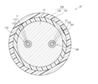
- FIG. 1 is a diagram showing a cross section perpendicular to the longitudinal direction of a multicore fiber according to a first embodiment of the present invention.
- FIG. 1 is a diagram showing a crosstalk measuring device in a first embodiment.
- 3 is a flowchart showing the procedure of a crosstalk measuring method according to the first embodiment of the present invention.
- 4 is a diagram showing the state of light propagation in the crosstalk measuring device of FIG. 3.
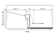
- FIG. 13 is a diagram showing measurement results using an OTDR.
- 5 is a diagram showing a cross section perpendicular to the longitudinal direction of a multi-core fiber according to a second embodiment of the present invention.
- FIG. FIG. 7 illustrates the refractive index profile of the core element of FIG. 6.
- 13A and 13B are diagrams showing measurement results using an OTDR according to the second embodiment.
- FIG. 13 is a diagram showing a crosstalk measuring device in a third embodiment.
- FIG. 13 is a diagram showing a crosstalk measuring device in
- First Embodiment 1 is a diagram showing a cross section perpendicular to the longitudinal direction of a multicore fiber of this embodiment.
- a multicore fiber 10 has a plurality of cores 11 and 12 capable of propagating light, and a clad 15 surrounding the outer circumferential surfaces of each of the cores 11 and 12.
- the outer circumferential surface of the clad 15 may be surrounded by a coating layer made of resin. Since the clad 15 surrounds the outer circumferential surfaces of each of the cores 11 and 12, it is also called a common clad.
- Each of the cores 11 and 12 has one end and the other end, and is arranged parallel to each other along the longitudinal direction of the multicore fiber 10.
- the refractive index of the cores 11 and 12 is higher than the refractive index of the cladding 15, and each of the cores 11 and 12 is capable of transmitting light. Therefore, each of the cores 11 and 12 is a first optical waveguide and a second optical waveguide, and the multicore fiber 10 is an optical device having a plurality of optical waveguides arranged parallel to each other.
- the cores 11 and 12 may be formed in a spiral shape and arranged parallel to each other, or the cores 11 and 12 may be formed in a straight line and arranged parallel to each other.
- the cores 11 and 12 are made of silica glass doped with a dopant that increases the refractive index, such as germanium (Ge), and the cladding 15 is made of silica glass without any dopants.
- the cores 11 and 12 may be made of silica glass without any dopants
- the cladding 15 may be made of silica glass doped with a dopant that decreases the refractive index, such as fluorine (F).
- the cores 11 and 12 may be made of silica glass doped with a dopant that increases the refractive index
- the cladding 15 may be made of silica glass doped with a dopant that decreases the refractive index.
- the dopants that increase the refractive index and the dopants that decrease the refractive index There are no particular limitations on the dopants that increase the refractive index and the dopants that decrease the refractive index.
- FIG. 2 is a diagram showing the crosstalk measuring device of this embodiment.
- the crosstalk measuring device 1 of this embodiment mainly comprises an OTDR 20, a processing unit 25, a connecting optical fiber 51, and an isolator 61, and measures crosstalk in a multicore fiber 10.
- the multicore fiber 10 has one end 17 and the other end 18. Note that in the following description, the one end 17 and the other end 18 may also be described as the one end 17 and the other end 18 of the core 11 and the core 12.
- the OTDR 20 is used by being optically connected to an optical fiber or the like, and emits pulsed light, and can measure the power of the light incident from the multi-core fiber 10, and can measure the time from when the pulsed light is emitted until the measured light is incident.
- the OTDR 20 is also a device that can measure optical losses such as transmission loss, bending loss, connection loss, etc. of optical fibers, detect breaks in optical fibers, etc., and measure the amount of light reflection, etc.
- a fan-in-fan-out device 30 is optically connected to the OTDR 20.
- the fan-in-fan-out device 30 has a plurality of optical waveguides (not shown) that can be optically connected individually to the cores 11 and 12 at one end 17 of the multicore fiber 10, and optical fibers 31 and 32 that include cores that are optically connected individually to the respective optical waveguides.
- the optical fibers 31 and 32 are approximately the same length.
- the core of the optical fiber 31 is optically connected to the OTDR 20.
- the optical waveguide optically connected to the core of the optical fiber 31 is optically connected to the core 11 of the multicore fiber 10. Therefore, the optical fiber 31 and the core 11 are optically connected, and the light emitted from the OTDR 20 is incident on the core 11.
- a fan-in-fan-out device 40 is optically connected to the other end 18 of the multicore fiber 10.
- the fan-in-fan-out device 40 has a configuration similar to that of the fan-in-fan-out device 30, and has a plurality of optical waveguides (not shown) that can be optically connected individually to the cores 11 and 12 of the multicore fiber 10, and optical fibers 41 and 42 including cores that are optically connected individually to the respective optical waveguides.
- the optical fibers 41 and 42 are approximately the same length. In this example, the core 11 and the core of the optical fiber 41 are optically connected, and the core 12 and the core of the optical fiber 42 are optically connected.
- the connection optical fiber 51 is a single-core fiber, for example, a single-mode fiber.
- the connection optical fiber 51 is divided into a part 51a and another part 51b.
- One end of the part 51a of the connection optical fiber 51 is optically connected to the optical fiber 41, and the other end is optically connected to one end of the isolator 61.
- One end of the other part 51b of the connection optical fiber 51 is optically connected to the other end of the isolator 61, and the other end is optically connected to the optical fiber 42. Therefore, the core of the optical fiber 41 and the core of the optical fiber 42 are optically connected via the core of the connection optical fiber 51 and the isolator 61.
- connection optical fiber 51 is a connection optical waveguide that optically connects the other end of the first optical waveguide, which is the core 11, and the other end of the second optical waveguide, which is the core 12.
- the core of the part 51a of the connection optical fiber 51 and the core of the other part 51b of the connection optical fiber 51 are a part and another part of the connection optical waveguide, respectively.
- the isolator 61 is provided on the connecting optical fiber 51, closer to the optical fiber 41 than the midpoint C of the connecting optical fiber 51.
- the forward direction of the isolator 61 is the direction from the optical fiber 42 side to the optical fiber 41 side.
- the isolator 61 attenuates light from the optical fiber 41 side and transmits light from the optical fiber 42 side to the optical fiber 41 side.
- the isolator 61 may also block the propagation of light from the optical fiber 41 side to the optical fiber 42.
- the isolator 61 is an optical component in which the loss of light incident from the first optical waveguide side (core 11) to the second optical waveguide side (core 12) is greater than the loss of light incident from the second optical waveguide side to the first optical waveguide side.
- the forward direction of the isolator 61 is the direction from the second optical waveguide side to the first optical waveguide side.
- the midpoint C is the point where the optical path between the other end 18 of the core 11 and the optical path between the other end 18 of the core 12 are roughly the same.
- the OTDR 20 is optically connected to the processing unit 25, and data related to the power of light received by the OTDR 20 is output to the processing unit 25.
- the processing unit 25 is a calculation device that uses the power of light measured by the OTDR 20 to calculate the magnitude of crosstalk.
- the processing unit 25 can be, for example, an integrated circuit such as a microcontroller, an integrated circuit (IC), a large-scale integrated circuit (LSI), or an application specific integrated circuit (ASIC), or an NC (Numerical Control) device.
- the processing unit 25 may or may not use a machine learning device.
- the processing unit 25 calculates the magnitude of crosstalk between the core 11 and the core 12 based on this data, as described below, and outputs data related to the calculated magnitude of crosstalk.
- the processing unit 25 and the OTDR 20 may be housed in a single housing, and some of the components may be shared.
- FIG. 3 is a flowchart showing the steps of the method for measuring crosstalk in this embodiment.
- the method for measuring crosstalk in this embodiment includes a connection step S1, a measurement step S2, and a processing step S3.
- a multi-core fiber 10 is prepared as an optical device to be measured, and is set in the crosstalk measurement device 1.
- the length of the multi-core fiber 10 is, for example, 21 km.
- the other end 18 of the core 11 and the other end 18 of the core 12 are optically connected via a core of a connecting optical fiber 51 in which an isolator 61 is provided on the optical fiber 41 side of the midpoint C.
- the length of the connecting optical fiber 51 is, for example, 10 km.
- an optical waveguide optically connected to the optical fiber 41 in the fan-in-fan-out device 40 is optically connected to the core 11 of the multi-core fiber 10, and an optical waveguide optically connected to the optical fiber 42 is optically connected to the core 12. Therefore, in this step, the other end of the first optical waveguide and the other end of the second optical waveguide are optically connected via the connecting optical waveguide. After this step, when light is incident on one end 17 of the core 11 , the light passes through the core of the connecting optical fiber 51 and enters the core 12 from the other end 18 of the core 12 .
- the OTDR 20 and the core 11 are also optically connected. Specifically, the optical waveguide optically connected to the optical fiber 31 in the fan-in-fan-out device 30 is optically connected to the core 11 of the multicore fiber 10. Therefore, the light emitted from the OTDR 20 enters the core 11 from one end 17 of the core 11.
- the core 11 of the multicore fiber 10 is optically connected to the OTDR 20, and the core 11 and the core 12 are optically connected via the core of the connecting optical fiber 51, as shown in Figure 2.
- the pulsed incident light output from the OTDR 20 is input from one end 17 of the core 11, which is the first optical waveguide, and the power of the output light output from one end 17 of the core 11, which includes pulsed light generated by crosstalk of the incident light from the core 11 to the core 12, which is the second optical waveguide, is measured by the OTDR 20.
- Figure 4 is a diagram showing the propagation of light in the crosstalk measurement device of Figure 3. The above will be explained in detail using this figure. Note that in Figure 4, the fan-in-fan-out devices 30 and 40 are shown in a simplified form.
- pulsed light is emitted from the OTDR 20.
- the wavelength width of this light is preferably 1 nm or more from the viewpoint of stable crosstalk measurement described later, more preferably 3 nm or more, and even more preferably 5 nm or more.
- the wavelength width of this light is preferably 30 nm or less from the viewpoint of measuring crosstalk at a specific wavelength.
- the pulse width and intensity of the light emitted from the OTDR 20 are appropriately adjusted so that the emitted light including the crosstalk light described later does not become saturated.
- an attenuator may be interposed between the OTDR 20 and the optical fiber 31.
- the pulsed light emitted from the OTDR 20 enters the core 11 from one end 17 of the core 11 as incident light L, and propagates through the core 11 from one end 17 to the other end 18.
- the pulsed incident light L propagating through the core 11 propagates from the core 11 to the core 12 while crosstalking. Since the incident light L is pulsed, the crosstalk light CL1 that crosstalks from the core 11 to the core 12 also becomes pulsed, and propagates from one end 17 to the other end 18 of the core 12 while traveling roughly parallel to the incident light L.
- the power of the incident light L decreases according to the distance it propagates through the core 11
- the power of the crosstalk light CL1 increases according to the distance it propagates through the core 12. Since the speed of light propagating through the core 11 and the core 12 is the same, the incident light L and the crosstalk light CL1 reach the other end 18 roughly at the same time.
- the incident light L and the crosstalk light CL1 are incident on the core of the connecting optical fiber 51 at approximately the same time via the fan-in-fan-out device 40.
- Incoming light L entering the connecting optical fiber 51 from the optical fiber 41 passes through point D of a portion 51a of the connecting optical fiber 51 and enters the isolator 61. Since the isolator 61 is provided closer to the core 11 than the midpoint C, the incoming light L is attenuated on the core 11 side than the midpoint C.
- the incoming light L attenuated by the isolator 61 enters the core 12 from the other end 18 of the core 12 via the fan-in-fan-out device 40 and propagates through the core 12.
- the attenuated incoming light L crosstalks into the core 11 while propagating through the core 12, but the incoming light L is, for example, sufficiently attenuated so that the crosstalk from the core 12 to the core 11 is small enough to be generally negligible.
- the crosstalk light CL1 is incident on the side opposite to the side where the incident light L is incident on the core of the connection optical fiber 51.
- the crosstalk light CL1 passes through the isolator 61.
- the crosstalk light CL1 passes through the attenuated incident light L at approximately the midpoint C of the connection optical fiber 51.
- the attenuated incident light L and the crosstalk light CL1 reach different ends of the connection optical fiber 51 approximately at the same time.
- the crosstalk light CL1 that passes through the connecting optical fiber 51 enters the core 11 from the other end 18 of the core 11 via the fan-in-fan-out device 40, propagates through the core 11, and exits from one end 17 of the core 11.
- the exit light including the crosstalk light CL1 that exits from the core 11 enters the OTDR 20 via the fan-in-fan-out device 30, is received by the OTDR 20, and the power of the exit light is measured by the OTDR 20.
- the OTDR 20 therefore measures the power of the outgoing light emitted from the one end of the first optical waveguide, including crosstalk light that occurs when the incident light crosstalks from the first optical waveguide to the second optical waveguide.
- Figure 5 shows the measurement results of the outgoing light received by the OTDR 20.
- the horizontal axis shows the propagation distance of the incident light L
- the vertical axis shows the power of the outgoing light received by the OTDR 20.
- the vertical axis of Figure 5 shows the power of the outgoing light in decibels as a ratio to a predetermined power set for the OTDR 20. For example, if this predetermined power is 1 mW, the unit of the vertical axis may be dBm.
- the backscattered light of the incident light L is measured as the outgoing light.
- the slope of the line showing the outgoing light in these sections shows the loss of the incident light L per unit length due to backscattering.
- pulsed light was measured at the boundary between the core 11 section and the connecting optical fiber 51 section, and this light indicates reflection in the fan-in-fan-out device 40, etc. Furthermore, within the connecting optical fiber 51 section, a waveform due to backscattered light from the connecting optical fiber was observed between the isolator 61 and the fan-in-fan-out device 40. This includes point D shown in Figure 2.
- the incident light L is attenuated, so the backscattered light of the incident light L is generally not measured in that section.
- Pulsed light is measured at approximately the midpoint C of the section representing the connecting optical fiber 51.
- the attenuated incident light L and the crosstalk light CL1 pass each other at approximately the midpoint C of the connecting optical fiber 51, and so this pulsed light represents the crosstalk light CL1.
- backscattered light is generally not measured at the midpoint C
- the power of the emitted light measured at approximately the midpoint C of the connecting optical fiber 51 is generally the power of the crosstalk light CL1.
- a pulse indicating the power of the crosstalk light CL1 is shown at approximately the midpoint of the section indicating the connecting optical fiber 51.
- the pulse width of the incident light L and the pulse width of the crosstalk light CL1 are approximately the same. Therefore, in order to prevent the pulse indicating the crosstalk light CL1 from overlapping the end of the connecting optical fiber 51, it is preferable that the length of the core of the connecting optical fiber 51, which is the connecting optical waveguide, is longer than the length corresponding to the half-maximum time width of the pulse of the incident light L.
- the length of the connecting optical fiber 51 is L SCF
- the half-maximum time width of the incident light L is ⁇ T pulse
- the effective refractive index of the core of the connecting optical fiber 51 is n
- the speed of light is c
- L SCF 1.2 ⁇ T pulse ⁇ c/n
- the OTDR 20 outputs data related to the measured power of the emitted light to the processing unit 25.
- Step S3 the processing unit 25 uses the power of the measured output light to determine the magnitude of crosstalk between the cores 11 and 12.
- the power P BS of the backscattered light generated by the attenuated incident light L in this region is negligibly small, so information on the power P BS that serves as a reference for the intensity of the incident light may not be obtained. Therefore, it is preferable to use the power P' BS of the point D on the part 51a of the connecting optical fiber 51 on the core 11 side of the isolator as the reference.
- the processing unit 25 obtains the crosstalk by considering the ratio of the powers P OUT and P' BS of the output light in this region, the crosstalk of the fan- in -fan-out devices 30 and 40, the loss coefficient of the connecting optical fiber 51 corresponding to the distance between the point D and the midpoint C, the insertion loss of the isolator in the forward direction, the backscattering coefficient of the connecting optical fiber 51, and the capture rate.
- the power of the pulsed light includes the power P XT_MCF of the crosstalk light CL1 and the power P XT_FIFO of the crosstalk in the fan-in-fan-out devices 30, 40. If the power P XT_FIFO is small enough to be ignored, the power of the pulsed light may be set as the power P XT-MCF of the crosstalk light CL1. However, from the viewpoint of more accurate calculation of the power P XT_MCF , it is preferable to set the power obtained by subtracting the power P XT_FIFO from the power of this pulsed light as the power P XT_MCF of the crosstalk light CL1.
- the power P XT_FIFO can be measured in advance.
- the fan-in-fan-out device 30 and the fan-in-fan-out device 40 are optically directly connected. In this way, the length of the multicore fiber 10 becomes 0, and when the power of the emitted light is measured in the same manner as in the above measurement step S2, the power P OUT of the pulsed light measured approximately at the midpoint C of the connection optical fiber 51 is the power P XT_FIFO .
- the processing unit 25 converts the power P XT_MCF of the crosstalk light CL1 thus obtained into the magnitude of crosstalk and outputs it. At this time, the processing unit 25 obtains the magnitude of crosstalk by taking into consideration the crosstalk of the fan-in-fan-out devices 30 and 40, the loss of the connecting optical fiber 51 corresponding to the distance between the point D and the midpoint C, the loss of the isolator in the forward direction, the backscattering coefficient of the connecting optical fiber 51, and the capture rate, with respect to the ratio of the power P' BS of the backscattered light of the incident light L which has returned to the OTDR from the point D on the part 51a of the connecting optical fiber 51 as the backscattered light of the incident light, passing through the other end 18 and one end 17 of the core 11.
- the power ratio may be converted into decibels and output.
- the processing unit 25 may also convert into decibels indicating the ratio to a predetermined power determined in the OTDR 20 and output it. In this way, the magnitude of crosstalk is obtained.
- the crosstalk obtained here is the crosstalk for one way of the multi-core fiber 10.
- the processing unit 25 may calculate the power P BS .
- the processing unit 25 may obtain the power P BS from the power of the emitted light in an area other than the area where the pulsed light is shown.
- the processing unit 25 may obtain the difference between the power P OUT of the emitted light in the area where the pulsed light is shown and the obtained power P BS of the backscattered light as the power of the pulsed light.
- the crosstalk measurement method may execute a second measurement step after the measurement step S2.
- the crosstalk from the core 12 to the core 11 is measured.
- both ends of the connection optical fiber 51 optically connected to the optical fiber 41 and the optical fiber 42 are swapped, and the OTDR 20 is optically connected to the optical fiber 32.
- the OTDR 20 measures the power P OUT of the emitted light and outputs it to the processing unit 25.
- the processing unit 25 obtains the crosstalk from the core 12 to the core 11 based on the power P OUT of the outputted emitted light.
- the processing unit 25 may obtain the crosstalk between the core 11 and the core 12 by averaging the crosstalk from the core 11 to the core 12 and the crosstalk from the core 12 to the core 11.
- the optical fiber 41 and the optical fiber 42 may have different lengths.
- the midpoint C may be a point where the optical path between the other end 18 of the core 11 and the optical path between the other end 18 of the core 12 and the midpoint C are substantially the same.
- the crosstalk was calculated based on the backscattered light power at point D on the portion 51a of the connecting optical fiber 51.
- the crosstalk can also be calculated using the backscattered light power on the core 11.
- the crosstalk measurement method of this embodiment can attenuate the incident light L on the core 11 side of the midpoint C using the isolator 61, and can attenuate the backscattered light generated by the incident light L at the midpoint C. This can prevent the backscattered light and noise generated from the backscattered light from being superimposed on the crosstalk light CL1. Therefore, the crosstalk measurement method of this embodiment can accurately measure the power of the crosstalk light CL1 and accurately measure the crosstalk.
- FIG. 6 is a diagram showing a cross section perpendicular to the longitudinal direction of the multicore fiber according to this embodiment.
- the multicore fiber 10 of this embodiment includes a core element 110, a core element 120, a cladding 15 that tightly surrounds the outer circumferential surfaces of each of the core elements 110 and 120, and a coating layer 130 that coats the outer circumferential surface of the cladding 15.
- the core element 110 includes a core 11, an outer core 112 that tightly surrounds the outer peripheral surface of the core 11, and a trench layer 113 that tightly surrounds the outer peripheral surface of the outer core 112.
- the core element 120 includes a core 12, an outer core 122 that tightly surrounds the outer peripheral surface of the core 12, and a trench layer 123 that tightly surrounds the outer peripheral surface of the outer core 122.
- Core element 110 and core element 120 have the same configuration, and outer core 112 and trench layer 113 are similar to outer core 122 and trench layer 123, so the following will describe core element 110.
- the diameter of the core 11 is, for example, 5.5 ⁇ m or more and 13.5 ⁇ m or less.
- the outer diameter of the outer core 112, i.e., the inner diameter of the trench layer 113, is 9 ⁇ m or more and 35 ⁇ m or less.
- the outer diameter of the trench layer 113 is 14 ⁇ m or more and 50 ⁇ m or less.
- the refractive index of the core 11 is higher than those of the outer core 112 and the cladding 15, and the relative refractive index difference of the core 11 with respect to the cladding 15 is, for example, 0.2% or more and 0.9% or less.
- the refractive index of the trench layer 113 is lower than those of the outer core 112 and the cladding 15.
- the relative refractive index difference of the trench layer 113 with respect to the cladding 15 is, for example, -0.9% or more and -0.1% or less.
- the refractive index of the outer core 112 may be the same as that of the cladding 15, or may be higher or lower than that of the cladding 15.
- the relative refractive index difference of the outer core 112 with respect to the cladding 15 is, for example, -0.3% or more and 0.3% or less.
- the trench layer 113 is made of silica glass doped with a dopant such as fluorine that lowers the refractive index.
- the outer core 112 may be doped with a dopant that increases the refractive index, a dopant that decreases the refractive index, or no dopant at all, depending on its relationship with the refractive index of the cladding 15. Note that whether or not dopants are added to the core 11, the outer core 112, the trench layer 113, and the cladding 15, and if so, the type of dopant, are not limited to the above.
- the multicore fiber may have a W-type refractive index profile core without the outer cores 112 and 122.
- the coating layer 130 includes an inner coating layer 131 that coats the outer peripheral surface of the cladding 15, and an outer coating layer 132 that coats the outer peripheral surface of the inner coating layer 131.
- the inner coating layer 131 and the outer coating layer 132 are each made of a resin such as an ultraviolet-curable resin, and the inner coating layer 131 and the outer coating layer 132 are made of different resins.
- FIG. 7 is a diagram showing a predetermined refractive index distribution of the core element 110 of the multicore fiber 10 of FIG. 6.
- the same symbols are written at positions indicating the relative refractive index difference of the core 11, the outer core 112, the trench layer 113, and the cladding 15.
- the relative refractive index difference of the outer core 112 with respect to the cladding 15 is 0.01%.
- the relative refractive index difference of the core 11 with respect to the outer core 112 is 0.35%.
- the relative refractive index difference of the trench layer 113 with respect to the cladding 15 is -0.4%.
- the crosstalk measurement device 1 and the procedure of the crosstalk measurement method are similar to those of the crosstalk measurement device 1 and the crosstalk measurement method according to the first embodiment, and therefore will not be described.
- Figure 8 is a diagram showing the measurement results of the outgoing light received by the OTDR 20.
- the horizontal axis indicates the propagation distance of the incident light L
- the vertical axis indicates the power of the outgoing light received by the OTDR 20.
- the vertical axis in Figure 8 indicates the power of the outgoing light in decibels as a ratio to a predetermined power set for the OTDR 20. For example, if this predetermined power is 1 mW, the unit of the vertical axis may be indicated in dBm.
- the multicore fiber 10 may not have at least one of the outer core 112 and the outer core 122. Also, it may not have at least one of the trench layer 113 and the trench layer 123. Also, it may not have at least one of the inner coating layer 131 and the outer coating layer 132.
- the crosstalk measurement method of this embodiment determines the crosstalk between core 11 and core 12, which are provided with a trench layer. As described above, the trench layer reduces the crosstalk between core 11 and core 12, and the crosstalk light CL1 is also small. This can increase the influence of backscattered light superimposed on crosstalk light CL1 and noise resulting from the backscattered light. Therefore, the crosstalk measurement method of this embodiment can have a significant effect of suppressing noise superimposed on crosstalk light CL1 and accurately measuring crosstalk.
- FIG. 9 is a diagram showing the crosstalk measuring device 1 in this embodiment.
- a circulator 71 is provided on the connecting optical fiber 51 on the optical fiber 41 side of the midpoint C of the connecting optical fiber 51.
- the circulator 71 has a first port 71a, a second port 71b, and a third port 71c.
- the first port 71a emits light that is incident on the third port 71c.
- the second port 71b emits light that is incident on the first port 71a. Light that is incident on the second port 71b does not generally exit from the first port 71a or the third port 71c.
- the first port 71a is optically connected to the other end of the part 51a of the connection optical fiber 51. Therefore, the first port 71a is optically connected to the core of the optical fiber 41 via the part 51a of the connection optical fiber 51.
- the second port 71b is optically connected to one end of the core of the optical fiber 72, which is a predetermined optical waveguide.
- the third port 71c is optically connected to one end of the other part 51b of the connection optical fiber 51. Therefore, the third port 71c is optically connected to the core of the optical fiber 42 via the other part 51b of the connection optical fiber 51.
- the circulator 71 outputs light from the optical fiber 41 from the second port 71b and outputs light from the optical fiber 42 to the optical fiber 41.
- the circulator 71 is an optical component in which the loss of light incident from the first optical waveguide side (core 11) to the second optical waveguide side (core 12) is greater than the loss of light incident from the second optical waveguide side to the first optical waveguide side.
- the optical fiber 72 is a single-core fiber, for example a single-mode fiber.
- the other end of the core of the optical fiber 72 is optically connected to the non-reflective termination 73.
- the non-reflective termination 73 prevents light from being reflected at the other end of the core of the optical fiber 72 and returning to the core of the optical fiber 72. Light from the optical fiber 41 that is reflected at the other end of the optical fiber 72 hardly comes out from either the first port 71a or the third port 71c, but the presence of the non-reflective termination 73 makes it possible to further prevent light that is reflected at the other end of the optical fiber 72 from emitting from the first port 71a or the third port 71c.
- connection step S1 differs from the connection step S1 according to the first embodiment in that the other end 18 of the core 11 and the other end 18 of the core 12 are optically connected via a core of a connecting optical fiber 51 in which a circulator 71 is provided on the optical fiber 41 side of the midpoint C.
- the other operations are similar to those in the connection step S1 according to the first embodiment, and therefore will not be described.
- Measurement step S2 In the measurement step S2, the incident light L incident on the connecting optical fiber 51 from the optical fiber 41 enters the first port 71a of the circulator 71 and exits from the second port 71b. The incident light L exiting from the second port 71b reaches the reflection-free termination 73 via the optical fiber 72 and is almost completely lost at the reflection-free termination 73.
- the crosstalk light CL1 enters the third port 71c of the circulator 71 from the optical fiber 42 side and exits to the optical fiber 41 side from the first port 71a.
- the other operations are similar to those in the measurement step S2 according to the first embodiment, and therefore will not be described.
- Processing step S3 is similar to processing step S3 in the first embodiment, so a description thereof will be omitted.
- the non-reflective termination 73 does not have to be provided at the other end of the core of the optical fiber 72.
- the length of the optical fiber 72 is adjusted so that the optical path between the first port 71a and the other end of the core of the optical fiber 72 is other than half the length of the optical path between the first port 71a and the midpoint C.
- the length of the optical fiber 72 is adjusted as described above, even if the incident light L is reflected at the other end of the optical fiber 72 and slightly emitted from the circulator 71 to the optical fiber 41 side or the optical fiber 42 side, the incident light L and the crosstalk light CL1 can be prevented from overlapping or passing each other at the midpoint C.
- the crosstalk measuring device 1 of this embodiment measures the crosstalk between the cores 11 and 12 of the multicore fiber 10 having a trench layer, but it may also measure the crosstalk between the cores 11 and 12 of the multicore fiber 10 not having a trench layer as in the first embodiment.
- the crosstalk measurement method of this embodiment can attenuate the incident light L on the core 11 side of the midpoint C using the circulator 71, and can attenuate the backscattered light generated by the incident light L at the midpoint C. Furthermore, the crosstalk light CL1 from the core 12 passes through the circulator 71 and enters the core 11. This can prevent the backscattered light of the incident light L and the noise generated from the backscattered light from being superimposed on the crosstalk light CL1. Therefore, the crosstalk measurement method of this embodiment can accurately measure the power of the crosstalk light CL1 and can accurately measure crosstalk.
- a non-reflective termination 73 is provided via the optical fiber 72 on the second port side from which the incident light L is emitted. Therefore, the incident light L emitted from the second port is prevented from being reflected at the end of the core of the optical fiber 72, and can be prevented from being emitted from the first port 71a to the optical fiber 41 and from the third port to the optical fiber 42 side.
- the incident light L and the crosstalk light CL1 are prevented from superimposing on each other, and the incident light L and the crosstalk light CL1 are prevented from passing each other, and the incident light L, the backscattered light of the incident light L, and the noise generated from the backscattered light are prevented from being superimposed on the crosstalk light CL1. Therefore, the crosstalk measurement method of this embodiment can accurately measure the power of the crosstalk light CL1 and accurately measure the crosstalk. However, even if the incident light L is reflected at the other end of the optical fiber 72, the reflected incident light L is attenuated, so the non-reflective termination 73 is not essential.
- the length of the optical fiber 72 is adjusted so that the optical path between the first port 71a and the other end of the core of the optical fiber 72 is other than half the length of the optical path between the first port 71a and the midpoint C. Therefore, the incident light L and the crosstalk light CL1 are prevented from overlapping, and the incident light L and the crosstalk light CL1 are prevented from passing each other, and the incident light L, the backscattered light of the incident light L, and the noise generated from the backscattered light are prevented from being overlapped on the crosstalk light CL1. Therefore, the crosstalk measurement method of this embodiment can accurately measure the power of the crosstalk light CL1 and accurately measure the crosstalk. However, even if the incident light L is reflected at the other end of the optical fiber 72, the reflected incident light L is attenuated, so that adjustment of the length of the optical fiber 72 is not essential.
- the other end of the portion 51a of the connecting optical fiber 51 may be optically connected to the second port 71b of the circulator 71.
- the circulator 71 may also have four or more ports.
- FIG. 10 is a diagram showing the crosstalk measuring device 1 in this embodiment.
- a coupler 81 is provided on the connecting optical fiber 51, closer to the optical fiber 41 than the midpoint C of the connecting optical fiber 51.
- the coupler 81 has a first port 81a, a second port 81b, and a third port 81c.
- the coupler 81 distributes the light incident on the first port 81a to the second port 81b and the third port 81c in a predetermined ratio and outputs the light.
- the first port 81a outputs light incident on the second port 81b and the third port 81c.
- the second port 81b outputs a portion of the light incident on the first port 81a.
- the third port 81c outputs another portion of the light incident on the first port 81a, and propagates the incident light to the first port 81a.
- the intensity of the light output from the second port 81b is stronger than the intensity of the light output from the third port 81c.
- the ratio of the intensity of the light output from the second port 81b to the intensity of the light output from the third port 81c may be 99:1.
- the first port 81a is optically connected to the other end of the part 51a of the connection optical fiber 51. Therefore, the first port 81a is optically connected to the core of the optical fiber 41 through the part 51a of the connection optical fiber 51.
- the second port 81b is optically connected to one end of the core of the optical fiber 82, which is a predetermined optical waveguide.
- the third port 81c is optically connected to one end of the other part 51b of the connection optical fiber 51. Therefore, the third port 81c is optically connected to the core of the optical fiber 42 through the other part 51b of the connection optical fiber 51.
- the coupler 81 outputs a part of the light from the optical fiber 41 to the optical fiber 82, and outputs the other part to the optical fiber 42.
- the coupler 81 also outputs the light from the optical fiber 42 and the light from the optical fiber 82 to the optical fiber 41.
- the coupler 81 is an optical component in which the loss of light incident from the first optical waveguide side (core 11) to the second optical waveguide side (core 12) is greater than the loss of light incident from the second optical waveguide side to the first optical waveguide side.
- the optical fiber 82 one end of which is optically connected to the second port 81b, is a single-core fiber, for example a single-mode fiber.
- the other end of the core of the optical fiber 82 is optically connected to the non-reflective termination 83.
- the non-reflective termination 83 prevents light from being reflected at the other end of the core of the optical fiber 82 and returning to the core of the optical fiber 82.
- the non-reflective termination 83 prevents light incident from the optical fiber 41 through the coupler 81 from being reflected at the other end of the optical fiber 82 and being emitted from the first port 81a to the optical fiber 41 side.
- connection step S1 differs from the connection step S1 according to the first embodiment in that the other end 18 of the core 11 and the other end 18 of the core 12 are optically connected via a core of a connecting optical fiber 51 in which a coupler 81 is provided on the optical fiber 41 side of the midpoint C.
- the other operations are similar to those in the connection step S1 according to the first embodiment, and therefore will not be described.
- the incident light L incident from the optical fiber 41 to the connection optical fiber 51 is incident on the first port 81a of the coupler 81, and a part of the incident light L is emitted from the second port 81b.
- a part of the incident light L emitted from the second port 81b reaches the reflection-free termination 83 via the optical fiber 82 and is mostly lost at the reflection-free termination 83.
- Another part of the incident light L incident on the first port 81a is emitted from the third port 81c of the coupler 81 to the optical fiber 42 side.
- the crosstalk light CL1 enters the third port 81c of the coupler 81 from the optical fiber 42 side and exits to the optical fiber 41 side from the first port 81a.
- the other operations are similar to those in the measurement step S2 according to the first embodiment, and therefore will not be described.
- Processing step S3 is similar to processing step S3 in the first embodiment, so a description thereof will be omitted.
- the reflection-free termination 83 does not have to be provided at the other end of the core of the optical fiber 82. Furthermore, the second port 81b does not have to be optically connected to the optical fiber 82. Even if the other end of the optical fiber 82 or the other end of the second port 81b to which the optical fiber 82 is not optically connected is not reflection-free terminated, the light reflected by Fresnel reflection is at most about 4%, and a portion of the incident light L is generally attenuated.
- the optical path from the first port 81a to the other end of the second port 81b may be different from the optical path from the first port 81a to the midpoint C.
- the incident light L from the optical fiber 41 is reflected at the other end of the second port 81b and emitted from the first port 81a
- the reflected incident light L and the crosstalk light CL1 can be prevented from overlapping.
- the optical path from the first port 81a to the other end of the second port 81b is shorter than half the optical path from the first port 81a to the midpoint C, the backscattered light of the optical fiber 82 can be prevented from overlapping with the crosstalk light CL1.
- the crosstalk measurement device 1 of this embodiment may also measure the crosstalk between the core 11 and the core 12 of the multicore fiber 10 of the first embodiment.
- the crosstalk measurement method of this embodiment uses the coupler 81 to emit a portion of the incident light L toward the optical fiber 82 on the core 11 side of the midpoint C. Therefore, the crosstalk measurement method can attenuate the incident light L on the core 11 side of the midpoint C and attenuate the backscattered light generated by the incident light L at the midpoint C. Furthermore, the crosstalk light CL1 from the core 12 passes through the coupler 81 and enters the core 11. This can prevent the backscattered light of the incident light L and the noise generated from the backscattered light from being superimposed on the crosstalk light CL1. Therefore, the crosstalk measurement method of this embodiment can accurately measure the power of the crosstalk light CL1 and accurately measure crosstalk.
- a non-reflective termination 83 is provided via an optical fiber 82 on the second port side from which the incident light L is emitted. Therefore, the incident light L emitted from the second port is prevented from being reflected at the end of the core of the optical fiber 82, and can be prevented from being emitted from the first port to the optical fiber 41 side. Therefore, the incident light L and the like are prevented from overlapping with the crosstalk light CL1, and the incident light L and the like are prevented from being superimposed on the crosstalk light CL1. Therefore, the crosstalk measurement method of this embodiment can accurately measure the power of the crosstalk light CL1 and accurately measure crosstalk. However, even if the incident light L is reflected at the other end of the optical fiber 72, the reflected incident light L is attenuated, so the non-reflective termination 83 is not essential.
- the arrangement and number of cores in the multicore fiber 10 may be different from those in the above embodiment.
- the multicore fiber 10 may include four cores.
- the processing unit 25 may further determine the magnitude of crosstalk between the core 11 and the other cores based on the determined magnitude of crosstalk between the core 11 and the core 12.
- the processing unit 25 determines the magnitude of crosstalk between the core 11 and the other cores using a relational equation showing the relationship between the magnitude of crosstalk between the core 11 and the core 12 and the magnitude of crosstalk between the core 11 and the other cores.
- the other cores may be optically connected to each other at the other end 18.
- a multi-core fiber has been described as an example of an optical device in which optical waveguides are arranged in parallel, but the optical device of the present invention is not limited to a multi-core fiber.
- the present invention may be applied to an optical fiber cable in which multiple optical fibers are arranged in an array, an optical fiber tape in which multiple optical fibers are arranged in a planar array, a multi-element fiber in which multiple bare optical fibers are arranged in a single coating layer, and crosstalk measurement of an entire transmission system.
- the gradient of the power of the backscattered light measured by the OTDR 20 is approximately the same in the core 11 and the connection optical fiber 51 sections. This indicates that the loss of the incident light L per unit length due to backscattering is approximately the same in the core 11 and the connection optical fiber 51 sections. Therefore, in the above embodiment, when the numerical aperture (NA) of the core 11 and the connection optical fiber 51 is approximately the same and light of the same power is propagated in each, the power of the backscattered light per unit length generated in each section is approximately the same.
- NA numerical aperture
- connection optical fiber 51 when light of the same power is propagated in the core 11 and the connection optical fiber 51, it is preferable that the power of the backscattered light per unit length generated in the connection optical fiber 51 is smaller than the power of the backscattered light per unit length generated in each of the cores 11.
- An example of such a connection optical fiber 51 is a hollow core optical fiber whose core is hollow.
- such a connecting optical fiber 51 may be an optical fiber in which the relative refractive index difference of the core of the connecting optical fiber 51 is smaller than that of the light propagating through the core of the multicore fiber 10, and the effective cross-sectional area of the propagating light is larger. This is because the power of the backscattered light is proportional to the numerical aperture (NA) corresponding to the relative refractive index difference. The ratio of the power of the crosstalk light to the power of the backscattered light becomes larger, making it easier to detect the crosstalk light.
- NA numerical aperture
- the crosstalk measurement device 1 may further measure at least one of the optical loss, reflection intensity, bending loss, and breakage in an optical device such as the multi-core fiber 10 using the OTDR 20.
- the form of the fan-in-fan-out devices 30, 40 is not particularly limited. Furthermore, the crosstalk measurement device 1 does not need to include at least one of the fan-in-fan-out devices 30, 40.
- the cores 11 and 12 of the multicore fiber 10 and the core of the connecting optical fiber 51 are optically directly connected.
- the connecting optical fiber 51 may be composed of a connection body of multiple optical fibers.
- the present invention provides a crosstalk measurement method and crosstalk measurement device that can accurately determine crosstalk using an OTDR, and is expected to be used in fields such as optical fiber communications.
Landscapes
- Chemical & Material Sciences (AREA)
- Analytical Chemistry (AREA)
- Physics & Mathematics (AREA)
- General Physics & Mathematics (AREA)
- Testing Of Optical Devices Or Fibers (AREA)
Priority Applications (2)
| Application Number | Priority Date | Filing Date | Title |
|---|---|---|---|
| CN202480042273.4A CN121359011A (zh) | 2023-07-26 | 2024-07-12 | 串扰测量装置和串扰测量方法 |
| JP2025535734A JPWO2025023063A1 (https=) | 2023-07-26 | 2024-07-12 |
Applications Claiming Priority (2)
| Application Number | Priority Date | Filing Date | Title |
|---|---|---|---|
| JP2023-121994 | 2023-07-26 | ||
| JP2023121994 | 2023-07-26 |
Publications (1)
| Publication Number | Publication Date |
|---|---|
| WO2025023063A1 true WO2025023063A1 (ja) | 2025-01-30 |
Family
ID=94375239
Family Applications (1)
| Application Number | Title | Priority Date | Filing Date |
|---|---|---|---|
| PCT/JP2024/025228 Pending WO2025023063A1 (ja) | 2023-07-26 | 2024-07-12 | クロストーク測定装置、及びクロストーク測定方法 |
Country Status (3)
| Country | Link |
|---|---|
| JP (1) | JPWO2025023063A1 (https=) |
| CN (1) | CN121359011A (https=) |
| WO (1) | WO2025023063A1 (https=) |
Citations (1)
| Publication number | Priority date | Publication date | Assignee | Title |
|---|---|---|---|---|
| JP2022111486A (ja) * | 2021-01-20 | 2022-08-01 | 日本電信電話株式会社 | 光学特性測定装置及び方法 |
-
2024
- 2024-07-12 CN CN202480042273.4A patent/CN121359011A/zh active Pending
- 2024-07-12 WO PCT/JP2024/025228 patent/WO2025023063A1/ja active Pending
- 2024-07-12 JP JP2025535734A patent/JPWO2025023063A1/ja active Pending
Patent Citations (1)
| Publication number | Priority date | Publication date | Assignee | Title |
|---|---|---|---|---|
| JP2022111486A (ja) * | 2021-01-20 | 2022-08-01 | 日本電信電話株式会社 | 光学特性測定装置及び方法 |
Non-Patent Citations (5)
| Title |
|---|
| K. TAKENAGAY. ARAKAWAS. TANIGAWAN. GUANS. MATSUOK. SAITOHM. KOSHIBA: "An Investigation on Crosstalk in Multi-Core Fibers by Introducing Random Fluctuation along Longitudinal Direction", IEICE TRAN. COMMUN, vol. E94-B, no. 2, 2011 |
| M. NAKAGAWAM. OHZEKIK. TAKENAGAK. ICHII: "Novel Inter-Core Crosstalk Measurement Method Using a Loopback and Bidirectional OTDR Technique", JOURNAL OF LIGHTWAVE TECHNOLOGY, vol. 41, 2023, pages 3842 - 3848 |
| M. NAKAZAWAM. YOSHIDAT. HIROOKA: "Nondestructive measurement of mode couplings along a multi-core fiber using a synchronous multi-channel OTDR", OPTICS EXPRESS, vol. 20, 2012, pages 12530 - 12540 |
| M. OHASHIK. KAWAZUA. NAKAMURAY. MIYOSHI: "Simple backscattered power technique for measuring crosstalk of multi-core fibers", OPTOELECTRONICS AND COMMUNICATIONS CONFERENCE, 2012, pages 1 - 25 |
| NAKAGAWA MAYU, OHZEKI MASAKI, TAKENAGA KATSUHIRO, ICHII KENTARO: "Novel Inter-Core Crosstalk Measurement Method Using a Loopback and Bidirectional OTDR Technique", JOURNAL OF LIGHTWAVE TECHNOLOGY, IEEE, USA, vol. 41, no. 12, 15 June 2023 (2023-06-15), USA, pages 3842 - 3848, XP093265045, ISSN: 0733-8724, DOI: 10.1109/JLT.2023.3263633 * |
Also Published As
| Publication number | Publication date |
|---|---|
| JPWO2025023063A1 (https=) | 2025-01-30 |
| CN121359011A (zh) | 2026-01-16 |
Similar Documents
| Publication | Publication Date | Title |
|---|---|---|
| US11322904B2 (en) | Optical amplifier and multi-core optical fiber | |
| US11555955B2 (en) | High backscattering waveguides | |
| Hayashi et al. | Characterization of crosstalk in ultra-low-crosstalk multi-core fiber | |
| WO2025023064A1 (ja) | クロストーク測定装置、及びクロストーク測定方法 | |
| WO2020171187A1 (ja) | モード依存損失測定装置およびモード依存損失測定方法 | |
| WO2018207915A1 (ja) | 非線形性測定方法および非線形性測定装置 | |
| Tuggle et al. | Record low loss 0.144 dB/km 2-core optical fiber for submarine transmission | |
| EP4524544A1 (en) | Crosstalk measuring method, and crosstalk measuring device | |
| Nakagawa et al. | Novel inter-core crosstalk measurement method using a loopback and bidirectional OTDR technique | |
| Tandon et al. | Record Low Loss 0.144 dB/km 2-Core Optical Fiber for Submarine Transmission | |
| WO2023152468A1 (en) | Optical time domain reflectometry for hollow core optical fibres | |
| Kobayashi et al. | Characterization of inter-core crosstalk of multi-core fiber as a function of bending radius with multi-channel OTDR | |
| WO2025023063A1 (ja) | クロストーク測定装置、及びクロストーク測定方法 | |
| KOBAYASHI et al. | Measurement of inter-core crosstalk of multicore fibers with optical time domain reflectometry | |
| Ohashi et al. | Optical fibers for space-division multiplexing | |
| JP2005062704A (ja) | 光モジュール、光減衰装置、光送受信モジュール並びに光導波部材 | |
| JP2025002425A (ja) | クロストーク測定方法、クロストーク測定装置、光損失測定方法、及び光損失測定装置。 | |
| Kawaguchi et al. | Behavior of Inter-core Crosstalk of Two-core Fiber in Submarine Cable | |
| CN219064543U (zh) | 一种多模光纤布里渊光时域分析传感装置 | |
| Zhao et al. | OTDR Enabled Multiple-Loopback Measurement of Inter-Core Crosstalk in MCF | |
| CN219064544U (zh) | 一种多模光纤布里渊光时域反射传感装置 | |
| Kamimura et al. | Return Loss Measurement Procedure for Multicore Fiber Connectors | |
| JP7545504B1 (ja) | マルチコアファイバ | |
| López et al. | Experimental characterization of transmission properties in multi-core plastic optical fibers | |
| JP7853507B1 (ja) | クロストーク測定方法 |
Legal Events
| Date | Code | Title | Description |
|---|---|---|---|
| 121 | Ep: the epo has been informed by wipo that ep was designated in this application |
Ref document number: 24845444 Country of ref document: EP Kind code of ref document: A1 |
|
| ENP | Entry into the national phase |
Ref document number: 2025535734 Country of ref document: JP Kind code of ref document: A |
|
| WWE | Wipo information: entry into national phase |
Ref document number: 2025535734 Country of ref document: JP |
|
| WWE | Wipo information: entry into national phase |
Ref document number: 2024845444 Country of ref document: EP |
|
| NENP | Non-entry into the national phase |
Ref country code: DE |