WO2025022945A1 - 送風装置及びドライヤ - Google Patents
送風装置及びドライヤ Download PDFInfo
- Publication number
- WO2025022945A1 WO2025022945A1 PCT/JP2024/023882 JP2024023882W WO2025022945A1 WO 2025022945 A1 WO2025022945 A1 WO 2025022945A1 JP 2024023882 W JP2024023882 W JP 2024023882W WO 2025022945 A1 WO2025022945 A1 WO 2025022945A1
- Authority
- WO
- WIPO (PCT)
- Prior art keywords
- impeller
- inlet
- cover
- axis
- dryer
- Prior art date
- Legal status (The legal status is an assumption and is not a legal conclusion. Google has not performed a legal analysis and makes no representation as to the accuracy of the status listed.)
- Pending
Links
Images



Classifications
-
- A—HUMAN NECESSITIES
- A45—HAND OR TRAVELLING ARTICLES
- A45D—HAIRDRESSING OR SHAVING EQUIPMENT; EQUIPMENT FOR COSMETICS OR COSMETIC TREATMENTS, e.g. FOR MANICURING OR PEDICURING
- A45D20/00—Hair drying devices; Accessories therefor
- A45D20/04—Hot-air producers
- A45D20/08—Hot-air producers heated electrically
- A45D20/10—Hand-held drying devices, e.g. air douches
- A45D20/12—Details thereof or accessories therefor, e.g. nozzles, stands
-
- F—MECHANICAL ENGINEERING; LIGHTING; HEATING; WEAPONS; BLASTING
- F04—POSITIVE - DISPLACEMENT MACHINES FOR LIQUIDS; PUMPS FOR LIQUIDS OR ELASTIC FLUIDS
- F04D—NON-POSITIVE-DISPLACEMENT PUMPS
- F04D17/00—Radial-flow pumps, e.g. centrifugal pumps; Helico-centrifugal pumps
- F04D17/02—Radial-flow pumps, e.g. centrifugal pumps; Helico-centrifugal pumps having non-centrifugal stages, e.g. centripetal
- F04D17/04—Radial-flow pumps, e.g. centrifugal pumps; Helico-centrifugal pumps having non-centrifugal stages, e.g. centripetal of transverse-flow type
-
- F—MECHANICAL ENGINEERING; LIGHTING; HEATING; WEAPONS; BLASTING
- F04—POSITIVE - DISPLACEMENT MACHINES FOR LIQUIDS; PUMPS FOR LIQUIDS OR ELASTIC FLUIDS
- F04D—NON-POSITIVE-DISPLACEMENT PUMPS
- F04D29/00—Details, component parts, or accessories
- F04D29/40—Casings; Connections of working fluid
- F04D29/42—Casings; Connections of working fluid for radial or helico-centrifugal pumps
- F04D29/44—Fluid-guiding means, e.g. diffusers
Definitions
- the present invention relates to a blower and a dryer.
- Air blowers are used in dryers, etc. (see, for example, Patent Document 1).
- one of the objectives of the present invention is to provide a blower and dryer that can suppress noise.
- a dryer comprises an impeller having a plurality of blades arranged in a rotational direction, and a housing that accommodates the impeller, the plurality of blades extending in a radial direction of the impeller, the housing having a fluid inlet, a fluid outlet, and a cover that covers the inlet, the cover having a plurality of extensions that are curved portions that extend in the rotational direction of the impeller, an opening is formed between two adjacent extensions of the plurality of extensions, and the pressure of the fluid between the plurality of extensions and the impeller is adjusted.
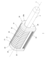
- FIG. 1 is a perspective view showing a schematic external appearance of a dryer according to an embodiment of the present invention, which is provided with a blower device according to an embodiment of the present invention.
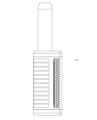
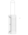
- FIG. 2 is a front view of the dryer of FIG. 1.
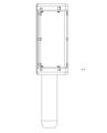
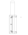
- FIG. 2 is a rear view of the dryer of FIG. 1.
- FIG. 2 is a right side view of the dryer of FIG. 1 .
- FIG. 2 is a left side view of the dryer of FIG. 1 .
- FIG. 2 is a plan view of the dryer of FIG. 1 .
- FIG. 2 is a bottom view of the dryer of FIG. 1 .
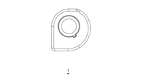
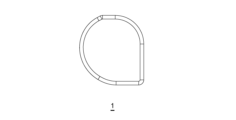
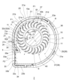
- 2 is a cross-sectional view showing a cross section perpendicular to the axis of the blower in the dryer of FIG. 1 .
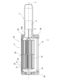
- FIG. 2 is a cross-sectional view showing a cross section of the blower taken along a plane including an axis.
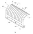
- FIG. FIG. 2 is a perspective view of a cover provided in the blower device.
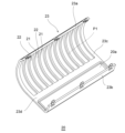
- FIG. 2 is a perspective view of a cover provided in the blower device.
- FIG. FIG. 11 is a perspective view showing a cover according to a modified example.
- 13 is a cross-sectional view showing a cross section perpendicular to the axis of a blower device including a cover according to a modified example.
- the dryer 1 is a hair dryer intended to be used on hair.
- the dryer according to the present invention is not limited to hair dryers, but also includes dryers used for other purposes.
- the blower device according to the present invention is not limited to dryers, but may also be applied to other devices such as air conditioners equipped with heaters and blowers equipped with heaters.
- the impeller 10 is rotatable around the axis x as the axis of rotation.
- the fluid suction direction F1 and the fluid blowing direction F2 intersect in the impeller 10.
- the impeller 10 also extends long in the direction of the rotation axis (axis x direction).
- the longitudinal direction of the impeller 10 is the axis x direction.
- the impeller 10 has a plurality of blades 11 extending radially, and the plurality of blades 11 extend long along the axis x, for example, as shown in FIG. 1, 8, and 9.
- the plurality of blades 11 are also arranged, for example, around the axis x.
- a space S extending in an approximately cylindrical shape is formed inside the plurality of blades 11, and the impeller 10 has a hollow shape.
- the shape of the blade 11 in a cross section perpendicular to the axis x is a curved shape (e.g., a circular arc shape), as shown in FIG. 8.
- the blades 11 are arranged, for example, parallel or approximately parallel to the axis x, and are arranged at a predetermined angle or at predetermined intervals around the axis x, and are arranged at equal or approximately equal intervals in the illustrated example.
- the impeller 10 is, for example, a crossflow fan.
- the housing 30 has a main body 31. As shown in FIG. 1 and 8, the main body 31 has a ventilation passage 31a.
- the ventilation passage 31a is a space in which the impeller 10 is housed, and is also a space through which the flow of fluid (airflow) F generated by the rotation of the impeller 10 passes.
- the main body 31 has two openings that open the ventilation passage 31a. One of the two openings is an inlet 32, and the other is an outlet 33.
- the ventilation passage 31a extends from the inlet 32 to the outlet 33 in the rotation direction R of the impeller 10.
- the fluid inlet 32 is an opening that allows gas as a fluid to be sucked into the impeller 10 from outside the housing 30.
- the outlet 33 is an opening that allows the gas discharged by the impeller 10 to be blown out to the outside of the housing 30.
- the inlet 32 is disposed outside the outer peripheral surface 10a (surface in the circumferential direction) of the impeller 10, and the inlet 32 is formed to face the outer peripheral surface 10a of the impeller 10.
- the inlet 32 is formed to face the ends 11a (inlet side) of the multiple blades 11 aligned in the rotation direction R.
- the outer peripheral surface 10a of the impeller 10 in the illustrated example, is a surface formed by the ends 11a of the multiple blades 11 aligned in the rotation direction R, and has multiple openings due to the gaps between the multiple blades 11, and has a shape different from a continuous surface.
- the outer peripheral surface 10a of the impeller 10 may be a cylindrical virtual surface extending along the axis x tangent to the ends 11a of the multiple blades 11.
- the inlet 32 is formed in the main body 31 so as to extend long along the axis x of the impeller 10, as shown in FIG. 1, and has a pair of ends 32a, 32b extending along the axis x, as shown in FIG. 8.
- the inlet 32 is also formed in the main body 31 so as to extend long in the circumferential direction around the axis x. As shown in FIG. 8, the inlet 32 has a pair of ends 32c, 32d extending in the rotational direction R.
- the area of the inlet 32 is larger than the area of the outlet 33.
- the inlet 32 is formed so that a large amount of gas is sucked into the impeller 10.
- the inlet 32 is shaped so that, for example, 1/2 of the surface of the impeller 10 or 1/3 to 2/3 of the surface is exposed to the space outside the main body 31 in the circumferential direction.
- the inlet 32 is shaped so that the entire outer peripheral surface of the impeller 10 or a part of the outer peripheral surface of the impeller 10 is exposed to the space outside the main body 31 in the axial x direction. Specifically, for example, as shown in FIG.
- the inlet 32 is opened so that the entire or part of the outer peripheral surface 10a of the impeller 10 in the axial x direction and half or approximately half of the outer peripheral surface 10a of the impeller 10 in the circumferential direction are exposed to the space outside the main body 31.
- the size and shape of the inlet 32 may be other sizes and shapes.
- the inlet 32 may also be covered with a filter to prevent dust and other foreign matter from entering the ventilation passage 31a.
- a nozzle 34 is formed in the main body 31, as shown in Figs. 1 and 8, for example.
- the nozzle 34 is formed in a portion of the ventilation passage 31a on the opposite side of the impeller 10 from the inlet 32 in the radial direction of the impeller 10.
- the nozzle 34 also extends along the rotation direction R of the impeller 10, and forms a flow path that moves away from the impeller 10 towards the outlet 33 (outside).
- the outlet 33 is formed at the tip (end) of the nozzle 34.
- the main body 31 has wall portions 35, 36 which form the ventilation passage 31a in the radial direction.
- the wall portions 35, 36 extend in the direction of the axis x, facing the outer peripheral surface 10a of the impeller 10.
- the wall portion 35 is a portion of the main body 31 extending between the end 32a of the inlet 32 and the end 33a of the outlet 33, as shown in FIG. 8.
- the ends 32a and 33a are formed in the wall portion 35.
- the wall portion 36 is a portion of the main body 31 extending between the end 32b of the inlet 32 and the end 33b of the outlet 33, as shown in FIG. 8.
- the ends 32b and 33b are formed in the wall portion 36.
- the wall portion 35 has a shape (outer shape) which is recessed toward the inside of the housing 30, and has a curved shape in cross section, as shown in FIG. 8. As shown in FIG. 8, the wall portion 35 has a shape that is bent convexly toward the ventilation passage 31a. In this way, the portion of the main body 31 between the inlet 32 and the outlet 33 has a bent shape.
- the cross section of the wall portion 36 is arc-shaped as shown in FIG. 8.
- the wall portion 36 extends in the circumferential direction of the impeller 10 so that the entire wall portion 36 faces the outer peripheral surface 10a of the impeller 10. As shown in FIG. 8, the wall portion 35 and the wall portion 36 face each other with the impeller 10 in between.
- the wall portion 35 may form a tongue of the ventilation passage 31a.
- the main body 31 has walls 37 and 38 which form the ventilation passage 31a in the direction of the axis x.
- the walls 37 and 38 face each other in the direction of the axis x via the impeller 10, and the walls 35 and 36 are disposed between the walls 37 and 38.
- the ends 32c and 32d of the inlet 32 are formed in the walls 37 and 38, respectively, and the ends 32c and 32d face each other in the direction of the axis x.
- an opening 22 is formed between two adjacent extension portions 21 among the multiple extension portions 21. That is, in the cover 20, the multiple extension portions 21 are arranged side by side in the axial x direction at intervals. For example, the multiple extension portions 21 are arranged parallel or approximately parallel to each other in the axial x direction. Note that the multiple extension portions 21 do not have to be arranged parallel to each other. Also, for example, the multiple extension portions 21 are arranged in the axial x direction at a predetermined interval, specifically at equal or approximately equal intervals. In this case, the multiple openings 22 are also arranged in the axial x direction at equal or approximately equal intervals.
- the width (width W1) of the extension portion 21 in the axis x direction is, for example, uniform or approximately uniform in the rotation direction R.
- the extension portion 21 is along a circular ring centered on the axis x.
- the width (width W2) of the opening 22 in the axis x direction is, for example, uniform or approximately uniform in the rotation direction R.
- the width of the extension portion 21 in the axis x direction may be uniform or approximately uniform in a direction inclined with respect to the rotation direction R.
- the extension portion 21 may be along a spiral with the axis x as the central axis.
- the width of the opening 22 in the axis x direction is also uniform or approximately uniform in a direction inclined with respect to the rotation direction R.
- the extension portion 21 may extend in a straight line from one end to the other end as described above when viewed in the radial direction, or may extend in a curved line when viewed in the radial direction.
- the extension portion 21 may extend in a serpentine manner along a circular ring centered on the axis x.
- the extension portion 21 is plate-shaped and has an inner peripheral surface 21a that faces the inner peripheral side, and an outer peripheral surface 21b that faces the outer peripheral side.
- the inner peripheral surface 21a extends along the axis x, for example, parallel or approximately parallel to the axis x.
- the outer peripheral surface 21b extends parallel or approximately parallel to the inner peripheral surface 21a, and the thickness of the extension portion 21 is uniform or approximately uniform over the range of the extension portion 21 in the rotational direction R.
- the thickness of the extension portion 21 is the distance between the inner peripheral surface 21a and the outer peripheral surface 21b.
- the width W1 of each extension portion 21 is, for example, smaller than the width W2 of each opening 22. Furthermore, the width W1 of the multiple extension portions 21 is smaller than the width W2 of the multiple openings 22. In other words, the sum of the widths W1 of all extension portions 21 of the cover 20 is smaller than the sum of the widths W2 of all openings 22 of the cover 20. Furthermore, the extension portions 21 are shaped to have the desired rigidity against the force exerted by the airflow that flows into the ventilation passage 31a from the outside through the inlet 32, which is generated by the rotation of the impeller 10. Specifically, the width W1, thickness, etc. of the extension portions 21 are set so as to have such desired rigidity.
- the inner circumferential surface 21a of the extension portion 21 is curved so as to face the space formed by the inlet 32 from the outside.
- the inner circumferential surface 21a of the extension portion 21 describes a circular arc or an approximately circular arc in cross section.
- the inner circumferential surface 21a extends parallel or approximately parallel to the axis x, and the outline described by the inner circumferential surface 21a has the same or approximately the same shape over the entire width of the extension portion 21 in the direction of the axis x.
- a first angle range ⁇ 0 is a predetermined angle range between the end (end 21c) of the extension portion 21 on the opposite side of the rotation direction R and the end (end 21d) of the extension portion 21 on the rotation direction R side, centered on the axis x.
- a second angle range ⁇ 1 is a predetermined angle range within the first angle range ⁇ 0 from the end 21c to a point a certain distance away in the rotation direction R
- a fourth angle range ⁇ 3 is a predetermined angle range from the end 21d to a point a certain distance away in the opposite direction of the rotation direction R
- a third angle range ⁇ 2 is a predetermined angle range between the second angle range ⁇ 1 and the fourth angle range ⁇ 3. As shown in FIG.
- the distance D1 between the inner peripheral surface 21a of the extension portion 21 and the outer peripheral surface 10a of the impeller 10 in the radial direction is greater in the second angle range ⁇ 1 than in the third angle range ⁇ 2. Furthermore, the distance D1 is greater in the fourth angle range ⁇ 3 than the distance D1 in the third angle range ⁇ 2.
- the distance D1 is constant or approximately constant in the third angle range ⁇ 2.
- the distance D1 increases toward end 21c in the opposite direction of the rotation direction R, and is maximum at end 21c.
- the distance D1 increases toward end 21d in the rotation direction R, and is maximum at end 21d.
- the distance D1 between the ends 11a of the multiple blades 11 of the impeller 10 and the extension portion 21 varies in the rotation direction R.
- the distance D1a in the third angle range ⁇ 2, i.e., at the center (middle portion) of the inlet 32 in the rotation direction R may be smaller or larger than the distances D1b, D1c in the second or fourth angle range ⁇ 1 or ⁇ 3, i.e., at the ends of the inlet 32 in the rotation direction R.
- the distance D1 between the ends 11a of the multiple blades 11 of the impeller 10 and the extension portion 21 may be the same or approximately the same in the first angle range ⁇ 0, i.e., across the rotation direction R.
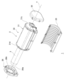
- Figures 12 and 13 are partially exploded perspective views of the dryer 1.
- the cover 20 forms part of the housing 30 and is adapted to be combined with the main body 31.
- the main body 31 is formed with a recess 31b that extends from the outer periphery to cover the inlet 32, and the cover 20 is accommodated in this recess 31b and attached to the main body 31.
- the housing 30 has cover support parts 25, 26 as side parts of the housing 30.
- the cover support parts 25, 26 are members for supporting the cover 20 with respect to the main body 31 and for holding the cover 20 attached to the main body 31.
- the cover support parts 25, 26 can be attached to the ends 31c, 31d of the main body 31 in the axial x direction, respectively, and are attached to the ends 31c, 31d, respectively, to support the cover 20 housed in the recess 31b of the main body 31 with respect to the main body 31.
- the cover support part 26 is attached to the end 31d on the handle 3 side of the dryer 1 described later, and has a hole 26b through which the handle 3 passes.
- the cover 20 is formed to cover the main body 31 from the inlet 32 to the outlet 33, for example.
- the cover 20 has a frame-shaped frame portion 23 and a panel 24 that is a portion extending along the axis x within the frame portion 23.
- the frame portion 23 forms the outer edge of the cover 20.
- the panel 24 extends so as to divide the frame portion 23 into two regions, and extends along the axis x.
- One of the two regions is region P1, which corresponds to the inlet 32, and has multiple extension portions 21 and multiple openings 22 formed therein.
- the other of the two regions corresponds to the outlet 33, and has a wider opening 20a.
- the multiple extensions 21 extend between the panel 24 and an upper frame portion 23a, which is a portion of the frame portion 23 that faces the panel 24 in the rotational direction R.
- the upper frame portion 23a extends along the axis x.
- an opening 20a extends between the panel 24 and a lower frame portion 23b, which is a portion of the frame portion 23 that faces the panel 24 in the opposite direction of the rotational direction R.
- the lower frame portion 23b extends along the axis x.
- side frame portions 23c and 23d extend between both ends of the upper frame portion 23a and both ends of the lower frame portion 23b in the frame portion 23.
- the side frame portions 23c and 23d are connecting portions that connect the upper frame portion 23a and the lower frame portion 23b.
- the side frame portions 23c and 23d are portions of the frame portion 23 that extend between the upper frame portion 23a and the lower frame portion 23b, and extend along the rotation direction R.
- the side frame portions 23c and 23d are shaped along the main body portion 31, and are curved along the wall portion 36 of the main body portion 31 on the region P1 side (see Fig. 8).
- the panel 24 extends between the side frame portions 23c and 23d.
- the opening 20a extends between the side frame portions 23c and 23d in the axis x direction.
- the shape and size of the opening 20a correspond to the shape and size of the space surrounded by the outlet 33, and the opening 20a covers the space inside the outlet 33.
- the ventilation passage 31a of the blower 2 is connected to the outside via the outlet 33 and the opening 20a of the cover 20.
- the panel 24 is formed to cover the wall portion 35 of the main body portion 31 from the outside, as shown in FIG. 8.
- the upper frame portion 23a contacts the portion of the wall portion 36 of the main body portion 31 that has a predetermined width from the end 32b of the inlet 32. Also, as shown in FIG. 8, the lower frame portion 23b contacts the portion of the wall portion 36 of the main body portion 31 that has a predetermined width from the end 33b of the outlet 33.
- the cover 20 has the above-mentioned configuration, and the multiple extensions 21 cover the inlet 32, acting as a guard to prevent objects from entering the inlet 32 from the outside.
- objects are prevented from entering the ventilation passage 31a from the outside through the inlet 32 and causing damage to the components of the blower 2, and the components of the blower 2, such as the impeller 10, are protected.
- the multiple extensions 21 extend along the rotation direction R of the impeller 10. Therefore, the distance D1 between the multiple extensions 21 and the outer peripheral surface 10a of the impeller 10 is constant or changes smoothly in the rotation direction R of the impeller 10 within the first angle range ⁇ 0. Specifically, for example, in the first angle range ⁇ 0, the ratio (%) of the minimum value to the maximum value of the distance D1 is, for example, 80% or more, preferably 90% or more. As a result, the airflow generated by the rotation of the impeller 10 flows along the inner peripheral surface 21a of the extensions 21, and the occurrence of a predetermined pressure fluctuation or pressure pulsation in the airflow flowing between the extensions 21 and the outer peripheral surface 10a of the impeller 10 is suppressed.
- the pressure of the fluid between the multiple extensions 21 and the impeller 10 is adjusted, and the change in pressure generated in the fluid between the extensions 21 and the impeller 10 when the impeller 10 rotates once is constant or gentle.
- This gently changing pressure is expressed, for example, as a ratio (%) of the minimum value to the maximum value of the pressure, and this ratio is, for example, 80% or more, preferably 90% or more. This prevents the multiple extensions 21 of the blower 2 from generating noise toward the surrounding area.
- the blower device 2 according to the embodiment of the present invention can suppress the generation of noise.
- FIG. 14 is an oblique view of a cover 20A according to a modified example of the cover 20, and FIG. 15 is a cross-sectional view showing a cross section perpendicular to the axis x of the blower device 2 including the modified cover 20A.
- the cover 20A has an extension portion 27, which is another extension portion extending in the axial direction x of the impeller 10 along the inlet 32.
- the cover 20A has, for example, two extension portions 27.
- the two extension portions 27 are provided near the end 21c of the extension portion 21 and near the end 21d of the extension portion 21, respectively.
- the extension portion 27 is provided in a second angle range ⁇ 1 near the end 21c of the extension portion 21 and in a fourth angle range ⁇ 3 near the end 21d of the extension portion 21.
- the extension portion 27 can improve the rigidity of the multiple extension portions 21.
- the extension portion 27 extending along the axis x is provided in the region of the angle range ⁇ 1,3 where the distance D1 between the extension portion 21 and the circumferential surface 10a of the impeller 10 is large, so that the generation of noise due to the extension portion 27 is suppressed.
- the extension portion 27 suppresses the generation of pressure fluctuations or pressure pulsations in the airflow flowing along the outer circumferential surface 10a of the impeller 10.
- the cover 20A may have the extension portion 27 only in one of the angle ranges ⁇ 1 and ⁇ 3.
- the cover 20A may have multiple extension portions 27 in the angle range ⁇ 1, and may have multiple extension portions 27 in the angle range 2.
- the dryer 1 has a blower 2 and a handle 3 attached to the blower 2. As shown in Figures 9, 12, and 13, the handle 3 extends from the end 31d of the main body 31 along the axis x.
- the dryer 1 also has a motor 4, which is housed inside the handle 3. The motor 4 is connected to the impeller 10 so as to be able to rotate the impeller 10. As a result, when the motor 4 rotates, the impeller 10 rotates.
- the dryer 2 also includes wiring 5 that electrically connects the motor 4 to an external device, such as an external power source.
- the wiring 5 is housed in a recess 35a, which is a bent portion of the wall 35 of the main body 31.
- the recess 35a extends along the axis x.
- the wall 35 is covered by the panel 24 of the cover 20. Therefore, the wiring 5 housed in the recess 35a of the wall 35 is covered by the panel 24, reducing the area exposed to the outside.
- the dryer 1 according to the embodiment of the present invention can suppress noise generation in the same way as the blower device 2.
- the above-described embodiments are intended to facilitate understanding of the present invention, and are not intended to limit the present invention. Furthermore, the above-described embodiments do not limit the use of the present invention, and the present invention may include anything as its use.
- the components of the above-described embodiments, as well as their arrangement, materials, conditions, shape, size, etc., are not limited to those exemplified, and may be modified as appropriate.
- the present invention includes differences that arise in implementation due to manufacturing tolerances, etc.
- the components shown in different embodiments may be partially substituted or combined to the extent that there is no technical contradiction.
- the configurations may be selectively combined as appropriate to achieve at least some of the above-described problems and effects.
Landscapes
- Engineering & Computer Science (AREA)
- Mechanical Engineering (AREA)
- General Engineering & Computer Science (AREA)
- Structures Of Non-Positive Displacement Pumps (AREA)
- Cleaning And Drying Hair (AREA)
Abstract
ドライヤ(1)の備える送風装置(2)は、回転方向(R)に並んだ複数の羽根(11)を有するインペラ(10)と、インペラ(10)を収容するハウジング(30)と、を備えている。複数の羽根(11)は、インペラ(10)の径方向に延在している。ハウジング(30)は、流体の流入口(32)と、流体の流出口(33)と、流入口(32)を覆うカバー(20)とを備えている。カバー(20)は、インペラ(10)の回転方向(R)に延在する、湾曲した部分である、延在部(21)を複数備えている。複数の延在部(21)のうち、互いに隣接する2つの延在部(21)の間には開口(22)が形成されている。複数の延在部(21)とインペラ(10)との間にある流体の圧力は調整されている。
Description
本発明は、送風装置及びドライヤに関する。
送風装置は、ドライヤ等に用いられている(例えば、特許文献1参照)。
送風装置には、従来から、騒音を発生しない構成が求められている。
そこで、本発明は、騒音を抑制することができる送風装置及びドライヤを提供することを課題の一つとする。
本発明の一態様に係るドライヤは、回転方向に並んだ複数の羽根を有するインペラと、前記インペラを収容するハウジングと、を備え、前記複数の羽根は、前記インペラの径方向に延在しており、前記ハウジングは、流体の流入口と、流体の流出口と、前記流入口を覆うカバーを備え、前記カバーは、前記インペラの回転方向に延在する湾曲した部分である延在部を複数備えており、前記複数の延在部のうち、互いに隣接する2つの延在部の間には開口が形成されており、前記複数の延在部と前記インペラとの間にある流体の圧力は調整されている。
以下、添付図面を参照して、本発明の一実施形態について説明する。図1は、本発明の実施形態に係る送風装置2を備える本発明の実施形態に係るドライヤ1の外観を概略的に示す斜視図である。図2~7は夫々、本発明の実施形態に係るドライヤ1の正面図、背面図、右側面図、左側面図、平面図及び底面図である。また、図8は、ドライヤ1における送風装置2の軸線xに直交する断面を示す断面図であり、図9は、軸線xを含む平面による送風装置2の断面を示す断面図である。なお、図面において、複数の部材については、その全てに符号は付されておらず、一部の符号は省略されている場合がある。ドライヤ1は、髪に対して用いられることが意図されたヘアドライヤである。本発明に係るドライヤは、ヘアドライヤに限られず、他の用途に用いられるドライヤも含む。また、本発明に係る送風装置の適用対象はドライヤに限られず、ヒータを備える空調機やヒータを備える送風機等の他の装置にも適用される。
図1~9に示されるように、ドライヤ1の備える送風装置2は、回転方向Rに並んだ複数の羽根11を有するインペラ10と、インペラ10を収容するハウジング30と、を備えている。複数の羽根11は、インペラ10の径方向に延在している。ハウジング30は、流体の流入口32と、流体の流出口33と、流入口32を覆うカバー20とを備えている。カバー20は、流入口32の外縁に沿ってインペラ10の回転方向Rに延在する、湾曲した部分である、延在部21を複数備えている。複数の延在部のうち、互いに隣接する2つの延在部21の間には開口22が形成されている。複数の延在部21とインペラ10との間にある流体の圧力は調整されている。以下、ドライヤ1及び送風装置2について具体的に説明する。
図1,8に示されるように、インペラ10は、軸線xを回転軸として回転可能になっている。インペラ10は、例えば図8に示されるように、流体の吸引方向F1と、流体の吹出し方向F2とが交差するようになっている。また、インペラ10は、回転軸方向(軸線x方向)に長く延在している。つまり、インペラ10の長手方向は、軸線x方向となっている。インペラ10は、上述したように、径方向に延びる複数の羽根11を有しており、複数の羽根11は、例えば図1,8,9に示されるように、軸線xに沿って長く延びている。また、インペラ10において、複数の羽根11は、例えば、軸線x周りに並べられている。このようにして、複数の羽根11の内部に、略円柱状に延びる空間Sが形成されており、インペラ10は中空の形状を備えている。羽根11の軸線xに直交する断面における形状は、例えば図8に示されるように、湾曲した形状(例えば円弧状)である。複数の羽根11は、具体的には例えば、軸線xに平行に又は略平行に配置されており、また、軸線x周りに所定の角度又は所定の間隔で配置されており、図示の例では等角度又は略等角度の間隔で配置されている。インペラ10は、例えば、クロスフローファンである。
図1,8に示されるように、ハウジング30は、本体部31を有している。図1,8に示されるように、本体部31は、通風路31aを備えている。通風路31aは、インペラ10が収容される空間であり、また、インペラ10の回転によって生じる流体の流れ(気流)Fが通る空間である。本体部31には、通風路31aを開放する2つの開口が形成されている。この2つの開口の一つが流入口32であり、他の一つが流出口33である。このように、通風路31aは、インペラ10の回転方向Rにおいて、流入口32から流出口33に向けて延在している。流体の流入口32は、ハウジング30の外部からインペラ10に流体としての気体が吸引されるようにするための開口である。一方、流出口33は、インペラ10が吐き出す気体がハウジング30の外部に吹き出されるようにするための開口である。
図1,8に示されるように、流入口32は、インペラ10の外側の周表面10a(周方向における表面)に対して外側に配置されており、流入口32は、このインペラ10の外側の周表面10aに面するように形成されている。言い換えれば、流入口32は、回転方向Rに並んだ複数の羽根11の端部11a(流入口側)に面するように形成されている。ここで、インペラ10の外側の周表面10aとは、図示の例であれば、回転方向Rに並んだ複数の羽根11の端部11aで形成される面であり、複数の羽根11の間隙により複数の開口を備えており、連続した面と異なる形状となっている。インペラ10の外側の周表面10aは、複数の羽根11の端部11aに接する軸線xに沿って延びる筒状の仮想の面であってもよい。流入口32は、例えば図1に示されるように、インペラ10の軸線xに沿って長く延びるように、本体部31に形成されており、図8に示されるように、軸線xに沿って延びる一対の端32a,32bを有している。また、流入口32は、軸線x周りの周方向にも長く延びるように、本体部31に形成されている。図8に示されるように、流入口32は、回転方向Rに延びる一対の端32c,32dを有している。
図1,8に示されるように、流入口32の面積は、流出口33の面積よりも大きく形成されている。流入口32は、インペラ10に多くの気体が吸引されるように形成されている。流入口32は、例えば、周方向において、インペラ10の表面の1/2又は表面の1/3以上2/3以下の部分が本体部31の外の空間に露出するような形状となっている。また、流入口32は、軸線x方向において、インペラ10の外側の周表面の全体又はインペラ10の外側の周表面の一部分が本体部31の外の空間に露出するような形状となっている。具体的には例えば、図1,8に示されるように、軸線x方向におけるインペラ10の外側の周表面10aの全体又は一部、及び周方向におけるインペラ10の外側の周表面10aの半分又は略半分が、本体部31の外の空間に露出するように、流入口32は開口している。なお、流入口32の大きさや形状は、他の大きさや形状であってもよい。また、流入口32は、通風路31a内に埃等の異物が進入しないように、フィルタで覆われていてもよい。
流出口33は、図1,8に示されるように、インペラ10の径方向に交差する方向において、インペラ10の外側の周表面10aに面するように形成されている。また、流出口33は、例えば図1に示されるように、本体部31に形成され、インペラ10の軸線xに沿って長く延びている。また、流出口33は、図1,8に示されるように、軸線xに沿って延びる一対の端33a,33bを有している。流出口33は、例えば、インペラ10と同じだけ、又はおおよそ同じだけ、軸線x方向に延びている。なお、流出口33は、軸線x方向において、インペラ10よりも長く、又はインペラ10よりも短く、軸線x方向に延びていてもよい。図8に示されるように、流出口33は、例えば、インペラ10の径方向においてインペラ10に対して流入口32と反対側の通風路31aの部分を開放するように形成されている。なお、流出口33の大きさや形状は、他の大きさや形状であってもよい。また、流入口32に対する流出口33の位置は、図示の位置に限られず、他の位置であってもよい。なお、流出口33は、フィルタや、ハニカム又は複数の格子を有する蓋等で覆われていてもよい。図示の例においては、ハニカムを有する蓋33cが流出口33に広がっている。
本体部31には、例えば図1,8に示されるように、ノズル34が形成されている。ノズル34は、インペラ10の径方向においてインペラ10に対して流入口32と反対側の通風路31aの部分に形成されている。また、ノズル34は、インペラ10の回転方向Rに沿って延在するとともに、流出口33(外側)に向かってインペラ10から離れる流路を形成する部分となっている。流出口33は、ノズル34の先端(端部)に形成されている。
図1,8に示されるように、本体部31は、径方向において通風路31aを形成する部分である壁部35,36を有している。壁部35,36は、インペラ10の外側の周表面10aに対向して、軸線x方向に延びている。壁部35は、図8に示されるように、本体部31の、流入口32の端32aと流出口33の端33aとの間を延びる部分である。端32a及び端33aは、壁部35に形成されている。また、壁部36は、図8に示されるように、本体部31の、流入口32の端32bと流出口33の端33bとの間を延びる部分である。端32b及び端33bは、壁部36に形成されている。壁部35は、ハウジング30の内側に凹んだ形状(外形)を備えており、図8に示されるように、断面において屈曲した形状を有している。壁部35は、図8に示されるように、例えば、通風路31a側に凸に屈曲するような形状を有している。このように、流入口32と流出口33との間にある本体部31の部分は、屈曲した形状を有している。一方、壁部36の断面は、図8に示されるように、弧状となっている。また、壁部36全体がインペラ10の外側の周表面10aに対向するように、壁部36はインペラ10の周方向に延びている。図8に示されるように、壁部35と壁部36とは、インペラ10を挟んで対向している。なお、壁部35は、通風路31aの舌部を形成していても構わない。
また、図1,8,9に示されるように、本体部31は、軸線x方向において通風路31aを形成する部分である壁部37,38を有している。壁部37と壁部38とは、軸線x方向において、インペラ10を介して対向しており、壁部37と壁部38との間に、壁部35及び壁部36が配置されている。図8に示されるように、流入口32の端32c,32dは夫々、壁部37,38に形成されており、端32cと端32dとは、軸線x方向で対向している。
送風装置2は、本体部31の内部にヒータ40を有している。ヒータ40は、例えば図8に示されるように、インペラ10の内部の空間Sに配置されている。ヒータ40は、空間S内で、軸線xに沿って延びている。ヒータ40は、例えば図8に示されるように、筒状(例えば円筒状又は略円筒状)になっており、ヒータ240の外周面の断面形状は、例えば、円形又は略円形となっている。なお、ヒータ40の形状はこの形状に限られない。また、図示のヒータ40の形状は、ヒータ40の構成部品が占める空間の形状を模式的に表したものである。ヒータ40の構成部品には、例えば、電熱線や電熱線を支持する部材等がある。また、ヒータ40は、本体部31の他の部分に設けられていてもよい。例えば、ヒータ40は、本体部31の壁部35,36,37,38の一部又は全部に設けられていてもよい。なお、ヒータ40には、電源に電気的に接続された配線で電流が供給可能になっている。
図10,11は、カバー20の斜視図であり、夫々異なる方向からカバー20を見た際の斜視図である。カバー20は、上述のように、流入口32を覆う部材であり、インペラ10等の送風装置2の構成の保護をする機能を有する部材である。図1,8に示されるように、カバー20は、例えば、後述するカバー20を支持する部材であるカバー支持部25,26の外周端部25a,26aに沿って、本体部31に外側から接触するように湾曲している。また、カバー20は、流入口32に対向する領域P1を有しており、この領域P1に、複数の延在部21と複数の開口22とを有している。領域P1は、例えば、その外縁が、径方向に沿って見て、流入口32の外縁、つまり、流入口32の端32a,32c,32b,32dに一致又は略一致している(図8参照)。なお、領域P1は、その外縁が、径方向に沿って見て、流入口32の外縁に一致していなくてもよい。
延在部21は、図8に示されるように、流入口32の外側において、流入口32の外縁である、壁部37に形成された端32c又は壁部38に形成された端32dに沿って延びている。図8に示されるように、延在部21は、回転方向Rに沿って、流入口32に跨って延びている。
上述のように、カバー20において、複数の延在部21のうち、互いに隣接する2つの延在部21の間には開口22が形成されている。つまり、カバー20において、複数の延在部21は、軸線x方向に、互いに間隔を空けて並んで設けられている。例えば、複数の延在部21は、互いに平行又は略平行に軸線x方向に並んでいる。なお、複数の延在部21は、互いに平行に並んでいなくてもよい。また、例えば、複数の延在部21は、所定の間隔で、具体的には等間隔又は略等間隔で軸線x方向に並んでいる。この場合、複数の開口22も、等間隔又は略等間隔で軸線x方向に並んでいる。
また、延在部21の軸線x方向の幅(幅W1)は(図10参照)、例えば、回転方向Rにおいて一様又は略一様となっている。つまり、延在部21は、軸線xを中心とする円環に沿っている。また、開口22の軸線x方向の幅(幅W2)は(図10参照)、例えば、回転方向Rにおいて一様又は略一様となっている。なお、延在部21の軸線x方向の幅は、回転方向Rに対して傾斜した方向において、一様又は略一様となっていてもよい。つまり、延在部21は、軸線xを中心軸とする螺線に沿っていてもよい。この場合、開口22の軸線x方向の幅も、回転方向Rに傾斜した方向おいて一様又は略一様となっている。なお、延在部21は、上述のように、一方の端から他方の端まで、径方向に見て、直線状に延びていてもよく、また、径方向に見て、曲線状に延びていてもよい。例えば、延在部21は、軸線xを中心とする円環に沿って、蛇行するように延びていてもよい。
図8に示されるように、延在部21は、板状になっており、内周側に面する面である内周面21aと、外周側に面する面である外周面21bとを有している。内周面21aは、軸線xに沿って延びており、例えば、軸線xに平行又は略平行に延びている。また、外周面21bは、内周面21aに平行又は略平行に延びており、延在部21の厚さは、回転方向Rの延在部21の範囲に亘って、一様又は略一様になっている。なお、延在部21の厚さは、内周面21aと外周面21bと間の距離である。
各延在部21の幅W1は、例えば、各開口22の幅W2より小さくなっている。また、複数の延在部21の幅W1は、複数の開口22の幅W2より小さくなっている。つまり、カバー20が有する全ての延在部21の幅W1の合計は、カバー20が有する全ての開口22の幅W2の合計よりも小さい。また、延在部21は、インペラ10の回転によって生じる、流入口32を介して外部から通風路31a内に流入する気流から受ける力に対して、所望とする剛性を有するような形態になっている。具体的には、このような所望の剛性を有するように、延在部21の幅W1や厚さ等が設定されている。
図8に示されるように、延在部21の内周面21aは、流入口32が形成する空間に外側から対向するように湾曲している。延在部21の内周面21aは、図8に示されるように、断面において、円弧又は略円弧を描いている。上述のように、内周面21aは、軸線xに平行又は略平行に延びており、延在部21の軸線x方向の幅全体に亘って、内周面21aが描く輪郭は同じ又は略同じ形状となっている。
図8に示されるように、軸線xを中心とする、延在部21の回転方向Rの反対方向側の端(端21c)と延在部21の回転方向R側の端(端21d)との間の所定の角度の範囲を、第1の角度範囲θ0とする。また、第1の角度範囲θ0の中の、端21cから回転方向Rに一定の距離離れた点までの所定の角度の範囲を、第2の角度範囲θ1とし、端21dから回転方向Rの反対方向に一定の距離離れた点までの所定の角度の範囲を、第4の角度範囲θ3とし、また、第2の角度範囲θ1と第4の角度範囲θ3との間の所定の角度の範囲を第3の角度範囲θ2とする。図8に示されるように、軸線xに直交する断面において、径方向における延在部21の内周面21aとインペラ10の外側の周表面10aとの間の距離D1は、第2の角度範囲θ1において、第3の角度範囲θ2における距離D1よりも大きくなっている。また、距離D1は、第4の角度範囲θ3において、第3の角度範囲θ2における距離D1よりも大きくなっている。
例えば、図8に示されるように、距離D1は、第3の角度範囲θ2において、一定又は略一定となっている。また、第2の角度範囲θ1において、距離D1は、回転方向Rの反対方向に端21cに向かうに連れて大きくなっており、端21cにおいて最大となっている。また、第4の角度範囲θ3において、距離D1は、回転方向Rに端21dに向かうに連れて大きくなっており、端21dにおいて最大となっている。
上述のように、インペラ10の複数の羽根11の端部11aと延在部21との間の距離D1は、回転方向Rにおいて異なっている。図8に示されるように、第3の角度範囲θ2における、つまり、回転方向Rにおける流入口32の中央(中間部)における距離D1aは、第2又は第4の角度範囲θ1又はθ3における、つまり、回転方向Rにおける流入口32の端部における距離D1b,D1cよりも、小さくなっていても又は大きくなっていても構わない。また、インペラ10の複数の羽根11の端部11aと延在部21との間の距離D1は、第1の角度範囲θ0において、つまり、回転方向Rに亘って、同じ又は略同じになっていてもよい。
図12,13は、ドライヤ1の部分分解斜視図である。カバー20は、ハウジング30の一部を形成しており、本体部31と組み合わされるようになっている。例えば、図8,12,13に示されるように、本体部31には、外周側から流入口32を覆うように広がる凹部31bが形成されており、カバー20は、この凹部31bに収容されて本体部31に取り付けられるようになっている。
また、図12,13に示されるように、ハウジング30は、カバー20及び本体部31に加えて、ハウジング30の側部としてのカバー支持部25,26を備えている。カバー支持部25,26は、本体部31に対してカバー20を支持し、カバー20が本体部31に取り付けられた状態に保持するための部材である。カバー支持部25,26は、例えば、本体部31の軸線x方向の端部31c,31dに夫々取り付け可能になっており、端部31c,31d夫々に取り付けられて、本体部31の凹部31bに収容されたカバー20を本体部31に対して支持するようになっている。カバー支持部26は、後述するドライヤ1のハンドル3側の端部31dに取り付けられ、ハンドル3を通す孔26bが形成されている。
次いで、カバー20の具体的な一例について説明する。図10,11に示されるように、カバー20は、例えば、流入口32から流出口33に亘って本体部31を覆うように形成されている。
カバー20は、図10,11に示されるように、枠状の枠部23と、枠部23内を軸線xに沿って延びる部分であるパネル24とを有している。枠部23は、カバー20の外縁を形成している。パネル24は、枠部23内を2つの領域に分けるように延びており、軸線xに沿って延びている。この2つの領域の一方は、領域P1であり、流入口32に対応しており、複数の延在部21及び複数の開口22が形成されている。2つの領域の他方は、流出口33に対応しており、開口20aが広がっている。
図10,11に示されるように、複数の延在部21は、パネル24と、パネル24に回転方向R側において対向する枠部23の部分である上枠部23aとの間に延びている。上枠部23aは、軸線xに沿って延びている。また、図10,11に示されるように、パネル24と、パネル24に回転方向Rの反対方向側において対向する枠部23の部分である下枠部23bとの間には、開口20aが広がっている。下枠部23bは、軸線xに沿って延びている。
また、図10,11に示されるように、枠部23において、上枠部23aの両端と下枠部23bの両端との夫々の間には、側枠部23c,23dが延びている。側枠部23c,23dは、上枠部23aと下枠部23bとを連結する連結部となっている。また、側枠部23c,23dは、上枠部23aと下枠部23bとの間に延びる枠部23の部分であり、回転方向Rに沿って延びている。側枠部23c,23dは、本体部31に沿った形状をしており、領域P1側においては、本体部31の壁部36に沿って湾曲している(図8参照)。側枠部23cと側枠部23dとの間には、パネル24が延びている。開口20aは、軸線x方向に、側枠部23cと側枠部23dとの間に延びている。
開口20aの形状及び大きさは、流出口33が囲む空間の形状及び大きさに対応しており、開口20aが、流出口33の内側にある空間を覆うようになっている。つまり、送風装置2の通風路31aは、流出口33及びカバー20の開口20aを介して外部に連通している。また、パネル24は、図8に示されるように、本体部31の壁部35を外側から覆うように形成されている。
図8に示されるように上枠部23aは、本体部31の壁部36のうち、流入口32の端32bから所定の幅を有する壁部36の部分に接触している。また、図8に示されるように下枠部23bは、本体部31の壁部36のうち、流出口33の端33bから所定の幅を有する壁部36の部分に接触している。
カバー20は、上述の構成を有しており、複数の延在部21が流入口32を覆っており、外から物が流入口32に侵入することを防ぐガードとなっている。また、物が外部から流入口32を介して通風路31a内に入って、送風装置2の構成に損傷が与えられることが抑制されており、インペラ10等の送風装置2の構成の保護が図られている。
また、複数の延在部21は、図8に示されるように、インペラ10の回転方向Rに沿って延びている。このため、複数の延在部21とインペラ10の外側の周表面10aとの距離D1は、第1の角度範囲θ0の範囲において、インペラ10の回転方向Rに、一定になっている又はなだらかに変化している。具体的には例えば、第1の角度範囲θ0において、距離D1の最大値に対する最小値の割合(%)は、例えば80%以上、好ましくは90%以上となっている。これにより、インペラ10の回転によって発生する気流は、延在部21の内周面21aに沿って流れ、延在部21とインペラ10の外側の周表面10aとの間を流れる気流に所定の圧力の変動又は圧力の脈動が生じることが抑制されている。このように、複数の延在部21とインペラ10との間にある流体の圧力は調整されて、インペラ10が1回転する際に延在部21とインペラ10との間の流体に発生する圧力の変化は、一定となっている又はなだらかとなっている。このなだらかに変化する圧力は、例えば圧力の最大値に対する最小値の割合(%)で表され、この割合は、例えば80%以上、好ましくは90%以上となっている。これにより、送風装置2の複数の延在部21によって周囲に向けて騒音が発生することが抑制されている。
上述のように、本発明の実施形態に係る送風装置2によれば、騒音の発生を抑制することができる。
次いで、カバー20の変形例について説明する。図14は、カバー20の変形例に係るカバー20Aの斜視図であり、図15は、変形例に係るカバー20Aを備える送風装置2の軸線xに直交する断面を示す断面図である。図14,15に示されるように、カバー20Aは、流入口32に沿って、インペラ10の軸線x方向に延在する他の延在部である延在部27を有している。カバー20Aは、例えば、延在部27を2つ有している。2つの延在部27は夫々、延在部21の端部21cの近傍と、延在部21の端部21dの近傍とに設けられている。具体的には例えば、延在部27は、延在部21の端部21c近傍の第2の角度範囲θ1と、延在部21の端部21d近傍の第4の角度範囲θ3とに設けられている。延在部27は、複数の延在部21の剛性を向上させることができる。また、軸線xに沿って延びる延在部27が、延在部21とインペラ10の周表面10aとの間の距離D1が大きい、角度範囲θ1,3の領域に設けられているため、延在部27による騒音の発生が抑制されている。つまり、延在部27によって、インペラ10の外側の周表面10aに沿って流れる気流に圧力の変動又は圧力の脈動が発生することが抑制されている。なお、カバー20Aは、延在部27を角度範囲θ1,θ3のいずれか一方にのみ有していてもよい。また、カバー20Aは、複数の延在部27を角度範囲θ1に複数有していてもよく、また、複数の延在部27を角度範囲2に複数有していてもよい。
次いで、本実施形態に係るドライヤ1について説明する。図1~7に示されるように、ドライヤ1は、送風装置2を有しており、送風装置2に取り付けられたハンドル3を有している。ハンドル3は、図9,12,13に示されるように、本体部31の端部31dから軸線xに沿って延びている。また、ドライヤ1はモータ4を有しており、モータ4は、ハンドル3の内部に収容されている。モータ4は、インペラ10を回転可能に、インペラ10に連結されている。これにより、モータ4が回転すると、インペラ10が回転する。
また、ドライヤ2は、外部の電源等の外部の装置にモータ4を電気的に接続する配線5を備えている。配線5は、図8に示されるように、本体部31の壁部35の屈曲した部分である凹部35aに収容されている。凹部35aは、軸線xに沿って延びている。上述のように、壁部35はカバー20のパネル24によって覆われている。このため、壁部35の凹部35aに収容された配線5は、パネル24に覆われ、外部に露出する面積を低減されている。
本発明の実施の形態に係るドライヤ1によれば、送風装置2と同様に、騒音の発生を抑制することができる。
以上、上記実施形態を通じて本発明を説明したが、本発明の技術的範囲は上記実施形態に記載の範囲には限定されない。上記実施形態に様々な変更又は改良を加えることができることが当業者には明らかである。そのような変更又は改良を加えた形態も本発明の技術的範囲に含まれ得ることが、請求の範囲の記載から明らかである。
以上説明した実施形態は、本発明の理解を容易にするためのものであり、本発明を限定して解釈するためのものではない。また、上述の実施形態は、本発明が利用される利用対象を限定するものではなく、本発明はあらゆるものをその利用対象として含み得る。上記実施形態が備える各構成要素並びにその配置、材料、条件、形状及びサイズ等は、例示したものに限定されるわけではなく、適宜変更することができる。例えば、本発明は、製造上の公差等の実施において発生する差を含むものである。また、技術的に矛盾しない範囲において、異なる実施形態で示した構成要素同士を部分的に置換し又は組み合わせることができる。また、上述した課題及び効果の少なくとも一部を奏するように、各構成を適宜選択的に組み合わせることができる。
1 ドライヤ、2 送風装置、3 ハンドル、4 モータ、10 インペラ、10a 周表面、11 羽根、11a 端部、12,13 端壁部、12a,13a 開口、12b,13b 支持部、12c,13c 内周面、12d,13d 外周面、20,20A カバー、20a 開口、21 延在部、21a 内周面、21b 外周面、21c,21d 端、22 開口、23 枠部、23a 上枠部、23b 下枠部、23c,23d 側枠部、24,27 延在部、25,26 カバー支持部、25a,26a,外周端、26b 孔、30 ハウジング、31 本体部、31a 通風路、31b 凹部、31c,31d 端部、32 流入口、32a,32b,32c,32d 端、33 流出口、33a,33b 端、33c 蓋、34 ノズル、35,36,37,38 壁部、35a 凹部、40 ヒータ、D1,D1a,D1b,D1c 距離、F 気流、F1 吸引方向、F2 吹出し方向、P1 領域、R 回転方向、S 空間、W1,W2 幅、x 軸線1、θ0,θ1,θ2,θ3 角度範囲
Claims (8)
- 回転方向に並んだ複数の羽根を有するインペラと、
前記インペラを収容するハウジングと、
を備え、
前記複数の羽根は、前記インペラの径方向に延在しており、
前記ハウジングは、流体の流入口と、流体の流出口と、前記流入口を覆うカバーを備え、
前記カバーは、前記インペラの回転方向に延在する湾曲した部分である延在部を複数備え、
前記複数の延在部のうち、互いに隣接する2つの延在部の間には開口が形成されており、
前記複数の延在部と前記インペラとの間にある流体の圧力は調整されている、
送風装置。 - 前記インペラの軸方向において、前記延在部の幅は、前記開口の幅より小さい、
請求項1に記載の送風装置。 - 前記インペラの軸方向において、前記複数の延在部の幅は、前記複数の開口の幅より小さい、
請求項1に記載の送風装置。 - 前記カバーは、前記インペラの軸方向に延在する他の延在部を1つ又は複数備えている、
請求項1から3のいずれかに記載の送風装置。 - 前記ハウジングは、流体の通風路を備え、
前記流体の通風路は、前記インペラの回転方向において、前記流入口から前記流出口に向けて延在する、
請求項1から4のいずれかに記載の送風装置。 - モータと、前記モータと外部の装置を電気的に接続する配線と、を備え、
前記流入口と前記流出口との間にある前記ハウジングの部分は、屈曲した形状を備え、
前記配線が前記ハウジングの部分に収容されている、
請求項1から5のいずれかに記載の送風装置。 - 請求項1から6のいずれかに記載の送風装置と、ハンドルとを備える、
ドライヤ。 - 前記ハンドルの内部にモータが収容されている、
請求項7に記載のドライヤ。
Priority Applications (1)
| Application Number | Priority Date | Filing Date | Title |
|---|---|---|---|
| CN202480046069.XA CN121463895A (zh) | 2023-07-21 | 2024-07-02 | 送风装置和干燥机 |
Applications Claiming Priority (2)
| Application Number | Priority Date | Filing Date | Title |
|---|---|---|---|
| JP2023-118864 | 2023-07-21 | ||
| JP2023118864A JP2025015940A (ja) | 2023-07-21 | 2023-07-21 | 送風装置及びドライヤ |
Publications (1)
| Publication Number | Publication Date |
|---|---|
| WO2025022945A1 true WO2025022945A1 (ja) | 2025-01-30 |
Family
ID=94374859
Family Applications (1)
| Application Number | Title | Priority Date | Filing Date |
|---|---|---|---|
| PCT/JP2024/023882 Pending WO2025022945A1 (ja) | 2023-07-21 | 2024-07-02 | 送風装置及びドライヤ |
Country Status (3)
| Country | Link |
|---|---|
| JP (1) | JP2025015940A (ja) |
| CN (1) | CN121463895A (ja) |
| WO (1) | WO2025022945A1 (ja) |
Citations (3)
| Publication number | Priority date | Publication date | Assignee | Title |
|---|---|---|---|---|
| JP2001214740A (ja) * | 2000-01-28 | 2001-08-10 | Denso Corp | クロスフローファン冷却装置 |
| KR20120019911A (ko) * | 2010-08-27 | 2012-03-07 | 주식회사 트레이스 | 크로스 플로우 타입의 임펠러를 구비한 원적외선 발생 헤어드라이어 |
| JP2015124624A (ja) * | 2013-12-25 | 2015-07-06 | ツインバード工業株式会社 | 送風機 |
-
2023
- 2023-07-21 JP JP2023118864A patent/JP2025015940A/ja active Pending
-
2024
- 2024-07-02 WO PCT/JP2024/023882 patent/WO2025022945A1/ja active Pending
- 2024-07-02 CN CN202480046069.XA patent/CN121463895A/zh active Pending
Patent Citations (3)
| Publication number | Priority date | Publication date | Assignee | Title |
|---|---|---|---|---|
| JP2001214740A (ja) * | 2000-01-28 | 2001-08-10 | Denso Corp | クロスフローファン冷却装置 |
| KR20120019911A (ko) * | 2010-08-27 | 2012-03-07 | 주식회사 트레이스 | 크로스 플로우 타입의 임펠러를 구비한 원적외선 발생 헤어드라이어 |
| JP2015124624A (ja) * | 2013-12-25 | 2015-07-06 | ツインバード工業株式会社 | 送風機 |
Also Published As
| Publication number | Publication date |
|---|---|
| CN121463895A (zh) | 2026-02-03 |
| JP2025015940A (ja) | 2025-01-31 |
Similar Documents
| Publication | Publication Date | Title |
|---|---|---|
| JP3107711B2 (ja) | 横流ファン | |
| JPWO2001011241A1 (ja) | 送風ユニットのファンガード及び空気調和装置 | |
| JP5206365B2 (ja) | 送風装置 | |
| JP2025122142A (ja) | 送風機 | |
| JP6070752B2 (ja) | 遠心送風機 | |
| JP2002005090A (ja) | 遠心ファン | |
| JP6468416B2 (ja) | クロスフローファン及びこれを備える空気調和機の室内機 | |
| WO2025022945A1 (ja) | 送風装置及びドライヤ | |
| WO2014050335A1 (ja) | 空気調和機 | |
| JPH05302600A (ja) | 遠心式送風機 | |
| US6425739B1 (en) | In-line centrifugal fan | |
| US7080970B2 (en) | Housing for axial flow heat-dissipating fan | |
| JP7310578B2 (ja) | 遠心送風機 | |
| JP2002054599A (ja) | 遠心ファン | |
| US11971049B2 (en) | Blower | |
| JP2009203908A (ja) | 送風機及び該送風機を備えた空気調和機 | |
| JP4506206B2 (ja) | ファン装置 | |
| US11873820B2 (en) | Water heater blower housing, impeller, and static tap system | |
| JP2004211971A (ja) | 空気調和機の室外機 | |
| JP7213415B2 (ja) | 送風装置 | |
| CN221711405U (zh) | 风嘴结构及吹风机 | |
| CN117189678B (zh) | 吊顶风扇和风扇灯 | |
| CN220726669U (zh) | 吊顶风扇和风扇灯 | |
| WO2024190327A1 (ja) | ドライヤ | |
| KR0141763B1 (ko) | 횡류형 송풍기의 리어가이더 |
Legal Events
| Date | Code | Title | Description |
|---|---|---|---|
| 121 | Ep: the epo has been informed by wipo that ep was designated in this application |
Ref document number: 24845327 Country of ref document: EP Kind code of ref document: A1 |
|
| NENP | Non-entry into the national phase |
Ref country code: DE |