WO2025022892A1 - 緩衝器 - Google Patents
緩衝器 Download PDFInfo
- Publication number
- WO2025022892A1 WO2025022892A1 PCT/JP2024/022634 JP2024022634W WO2025022892A1 WO 2025022892 A1 WO2025022892 A1 WO 2025022892A1 JP 2024022634 W JP2024022634 W JP 2024022634W WO 2025022892 A1 WO2025022892 A1 WO 2025022892A1
- Authority
- WO
- WIPO (PCT)
- Prior art keywords
- washer
- passage
- stopper member
- piston rod
- shock absorber
- Prior art date
- Legal status (The legal status is an assumption and is not a legal conclusion. Google has not performed a legal analysis and makes no representation as to the accuracy of the status listed.)
- Pending
Links
Images


Classifications
-
- F—MECHANICAL ENGINEERING; LIGHTING; HEATING; WEAPONS; BLASTING
- F16—ENGINEERING ELEMENTS AND UNITS; GENERAL MEASURES FOR PRODUCING AND MAINTAINING EFFECTIVE FUNCTIONING OF MACHINES OR INSTALLATIONS; THERMAL INSULATION IN GENERAL
- F16F—SPRINGS; SHOCK-ABSORBERS; MEANS FOR DAMPING VIBRATION
- F16F9/00—Springs, vibration-dampers, shock-absorbers, or similarly-constructed movement-dampers using a fluid or the equivalent as damping medium
- F16F9/10—Springs, vibration-dampers, shock-absorbers, or similarly-constructed movement-dampers using a fluid or the equivalent as damping medium using liquid only; using a fluid of which the nature is immaterial
- F16F9/14—Devices with one or more members, e.g. pistons, vanes, moving to and fro in chambers and using throttling effect
- F16F9/16—Devices with one or more members, e.g. pistons, vanes, moving to and fro in chambers and using throttling effect involving only straight-line movement of the effective parts
- F16F9/18—Devices with one or more members, e.g. pistons, vanes, moving to and fro in chambers and using throttling effect involving only straight-line movement of the effective parts with a closed cylinder and a piston separating two or more working spaces therein
- F16F9/19—Devices with one or more members, e.g. pistons, vanes, moving to and fro in chambers and using throttling effect involving only straight-line movement of the effective parts with a closed cylinder and a piston separating two or more working spaces therein with a single cylinder and of single-tube type
-
- F—MECHANICAL ENGINEERING; LIGHTING; HEATING; WEAPONS; BLASTING
- F16—ENGINEERING ELEMENTS AND UNITS; GENERAL MEASURES FOR PRODUCING AND MAINTAINING EFFECTIVE FUNCTIONING OF MACHINES OR INSTALLATIONS; THERMAL INSULATION IN GENERAL
- F16F—SPRINGS; SHOCK-ABSORBERS; MEANS FOR DAMPING VIBRATION
- F16F9/00—Springs, vibration-dampers, shock-absorbers, or similarly-constructed movement-dampers using a fluid or the equivalent as damping medium
- F16F9/32—Details
- F16F9/58—Stroke limiting stops, e.g. arranged on the piston rod outside the cylinder
Definitions
- the present invention relates to a shock absorber.
- This application claims priority based on Japanese Patent Application No. 2023-119001, filed in Japan on July 21, 2023, the contents of which are incorporated herein by reference.
- Some shock absorbers have elastic members that absorb the shock when fully extended (see, for example, Patent Documents 1 to 3).
- Shock absorbers are required to generate a stable damping force.
- the present invention therefore aims to provide a shock absorber that can generate a stable damping force.
- a shock absorber employs the following configuration: A cylinder in which a working fluid is sealed; a piston slidably fitted within the cylinder to divide the interior of the cylinder into two chambers; A rod guide that closes the cylinder; a piston rod that is inserted through the rod guide, has a first end connected to the piston, and has a second end extending to the outside of the cylinder; A stopper member provided on the piston rod; a deformable elastic member that is provided between the stopper member and the rod guide, that is formed so that the working fluid can flow between a radial outer periphery and the cylinder, and that moves together with the piston rod; a washer provided between the stopper member and the elastic member; Equipped with A first passage through which the working fluid can flow is formed between the radial outer circumferential surface of the washer and the cylinder; a second passage through which the working fluid can flow is formed between a radially inner circumferential surface of the washer and the piston
- the shock absorber according to the above aspect of the present invention makes it possible to generate a stable damping force.
- FIG. 1 is a cross-sectional view showing a shock absorber according to a first embodiment of the present invention.
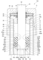
- 1 is a cross-sectional view of a main portion of a shock absorber according to a first embodiment of the present invention
- FIG. 6 is a cross-sectional view of a main portion of a shock absorber according to a second embodiment of the present invention.
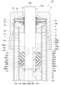
- FIG. 11 is a cross-sectional view of a main portion of a shock absorber according to a third embodiment of the present invention.
- FIG. 11 is a cross-sectional view of a main portion of a shock absorber according to a fourth embodiment of the present invention.
- FIG. 13 is a cross-sectional view of a main portion of a shock absorber according to a fifth embodiment of the present invention.
- FIG. 1 shows a shock absorber 11 of a first embodiment.
- This shock absorber 11 is used in a suspension system of a vehicle such as an automobile or a railroad car. Specifically, the shock absorber 11 is used in a suspension system of an automobile.
- the shock absorber 11 is a double-tube shock absorber equipped with a cylinder 17 having an inner tube 15 and an outer tube 16.
- the inner tube 15 is cylindrical.
- the outer tube 16 is a bottomed tube having a larger diameter than the inner tube 15.
- the outer tube 16 is provided radially outside the inner tube 15 and coaxially with the inner tube 15.
- a reservoir chamber 18 is formed between the outer tube 16 and the inner tube 15.
- the outer tube 16 has a body member 20 and a bottom member 21.
- the body member 20 is a stepped cylinder with a larger diameter at its axial middle portion than at both axial ends.
- the bottom member 21 is fitted and fixed to one axial end of the body member 20.
- the fitting portion of the bottom member 21 with the body member 20 and the body member 20 form the cylindrical body portion 22 of the outer tube 16.
- the body portion 22 is stepped.
- the portion radially inward from the fitting portion of the bottom member 21 with the body member 20 forms the bottom portion 23 of the outer tube 16.
- the bottom portion 23 closes one axial end of the body portion 22.
- the side of the body portion 22 opposite the bottom portion 23 forms an opening 24.
- the opening 24 of the outer tube 16 is also provided at one axial end of the cylinder 17.
- the bottom portion 23 of the outer tube 16 is also provided at the other axial end of the cylinder 17. In other words, one axial end of the cylinder 17 is the opening 24, and the other axial end is the bottom
- a mounting eye (not shown) is fixed to the side of the bottom 23 opposite the opening 24.
- the mounting eye is connected to the wheel side of the vehicle.
- a spring seat 25 is attached to the outer periphery of the body 22.
- the spring seat 25 receives the lower end of a spring (not shown) that supports the vehicle body.
- the inner tube 15 is a one-piece molded product made of a single piece of metal material, and is cylindrical.
- the inner periphery 15a of the inner tube 15 is cylindrical.
- the shock absorber 11 includes a valve body 27 and a rod guide 28.
- the valve body 27 is annular and is provided at one axial end of the inner cylinder 15 and the outer cylinder 16.
- the rod guide 28 is annular and is provided at the other axial end of the inner cylinder 15 and the outer cylinder 16.
- the valve body 27 constitutes the base valve 30, and has a stepped outer periphery. The valve body 27 is placed on the bottom 23. At that time, the valve body 27 is positioned radially relative to the outer cylinder 16 at the large diameter part of the outer periphery.
- the rod guide 28 has a rod guide body 32 and a collar 33.
- the rod guide body 32 is made of metal and has an annular shape.
- the rod guide body 32 has a large diameter portion 35 and a small diameter portion 36 on its outer periphery.
- the outer diameter of the large diameter portion 35 is larger than the outer diameter of the small diameter portion 36.
- the rod guide body 32 has a stepped outer periphery.
- the collar 33 is cylindrical.
- the collar 33 is formed by coating the inner periphery of a metal cylinder with a material having high sliding properties. The collar 33 is fitted and fixed to the inner periphery of the rod guide body 32.
- the rod guide 28 is fitted to the inner periphery of the opening 24 side of the trunk portion 22 of the outer tube 16 at the large diameter portion 35 of the rod guide body 32.
- the end surface 28a of the rod guide 28 at the end opposite the large diameter portion 35 in the axial direction is flat and extends perpendicular to the central axis of the rod guide 28.
- the end surface 28a is formed on the rod guide body 32 and the collar 33.
- one axial end of the inner tube 15 is fitted into the small diameter portion of the outer periphery of the valve body 27 until it axially abuts against the large diameter portion of the valve body 27.
- One axial end of the inner tube 15 engages with the bottom 23 of the outer tube 16 via the valve body 27.
- the other axial end of the inner tube 15 is fitted into the outer periphery of the small diameter portion 36 of the rod guide main body 32 until it axially abuts against the large diameter portion 35 of the rod guide main body 32.
- the other end of the inner tube 15 engages with the body 22 of the outer tube 16 via the rod guide 28.
- the inner tube 15 is positioned axially and radially relative to the outer tube 16.
- the valve body 27 and the bottom 23 communicate with each other through a passage groove 40 formed in the valve body 27.
- a reservoir chamber 18 is formed, similar to the space between the inner cylinder 15 and the outer cylinder 16.
- the shock absorber 11 is provided with an annular rod seal 41.
- the rod seal 41 is provided on the opposite side of the bottom 23 of the rod guide 28. This rod seal 41 is also fitted to the inner periphery of the body 22, like the rod guide 28.
- An engagement portion 43 is formed on the end of the body 22 opposite the bottom 23. The engagement portion 43 is formed by plastically deforming the body member 20 radially inward by crimping processing such as curling.
- the rod seal 41 is sandwiched between the engagement portion 43 and the rod guide 28. At that time, the rod seal 41 is pressed against the inner periphery of the body 22 by the rod guide 28. As a result, the rod seal 41 closes the opening 24 of the outer cylinder 16. In other words, the rod guide 28 and the rod seal 41 close the opening 24 at the end of the cylinder 17.
- the rod seal 41 is specifically an oil seal.
- the shock absorber 11 includes a piston 45.
- the piston 45 is slidably disposed within the cylinder 17.
- the piston 45 is slidably fitted within the inner tube 15 of the cylinder 17.
- the piston 45 divides the inner tube 15 into two chambers, a first chamber 48 and a second chamber 49.
- the first chamber 48 is disposed between the piston 45 and the rod guide 28 within the inner tube 15.
- the second chamber 49 is disposed between the piston 45 and the valve body 27 within the inner tube 15.
- the second chamber 49 is separated from the reservoir chamber 18 by the valve body 27.
- the first chamber 48 and the second chamber 49 are filled with oil L as a working fluid.
- the reservoir chamber 18 is filled with oil L and gas G as a working fluid.
- the shock absorber 11 is equipped with a piston rod 51.
- the piston rod 51 has a first axial end portion disposed inside the cylinder 17.
- the piston rod 51 has this first end portion connected to the piston 45.
- the piston rod 51 has a second end portion opposite the first axial end portion extending to the outside of the cylinder 17 through the opening 24 of the outer tube 16.
- the piston rod 51 is made of metal and passes through the first chamber 48.
- the piston rod 51 does not pass through the second chamber 49. Therefore, the first chamber 48 is a rod side chamber through which the piston rod 51 passes.
- the second chamber 49 is a bottom side chamber on the bottom 23 side of the cylinder 17.
- the piston rod 51 has a second end portion extending to the outside from the cylinder 17 connected to the vehicle body.
- the piston rod 51 has a main shaft portion 52 and a mounting shaft portion 53 on the first end side.
- the outer diameter of the mounting shaft portion 53 is smaller than the outer diameter of the main shaft portion 52.
- the outer peripheral surface 52a of the main shaft portion 52 is cylindrical.
- the mounting shaft portion 53 side of the piston rod 51 is inserted into the cylinder 17.
- the piston 45 is connected to the mounting shaft portion 53 of the piston rod 51 by a nut 54.
- the piston rod 51 is inserted into the rod guide 28 and the rod seal 41 at the main shaft portion 52 and extends from the cylinder 17 to the outside.
- the rod guide 28 and the rod seal 41 are provided on the side of the cylinder 17 from which the piston rod 51 extends.
- the rod guide 28 supports the piston rod 51 so that it can slide.
- the piston rod 51 is guided by the rod guide 28 at the outer peripheral surface 52a of the main shaft portion 52.
- the piston rod 51 moves axially together with the piston 45 relative to the cylinder 17.
- the piston 45 moves toward the first chamber 48.
- the piston 45 moves toward the second chamber 49.
- the rod seal 41 is provided on the side where the piston rod 51 of the cylinder 17 extends, i.e., on the opening 24 side of the outer tube 16.
- the rod seal 41 seals between the body 22 of the outer tube 16 and the main shaft 52 of the piston rod 51 by means of the rod guide 28, preventing the oil liquid L in the inner tube 15 and the gas G and oil liquid L in the reservoir chamber 18 from leaking out to the outside.
- the piston 45 is formed with a passage 55 and a passage 56. Both the passage 55 and the passage 56 pass through the piston 45 in the axial direction.
- the passages 55, 56 can communicate between the first chamber 48 and the second chamber 49.
- the shock absorber 11 includes a disk valve 57 and a disk valve 58.
- the disk valve 57 is provided on the side of the piston 45 opposite the bottom 23 in the axial direction.
- the disk valve 57 is annular, and closes the passage 55 by abutting against the piston 45.
- the disk valve 57 opens the passage 55 by deforming so that its outer periphery is separated from the piston 45.
- the disk valve 58 is provided on the bottom 23 side of the piston 45 in the axial direction.
- the disk valve 58 is annular, and closes the passage 56 by abutting against the piston 45.
- the disk valve 58 opens the passage 56 by deforming so that its outer periphery is separated from the piston 45.
- the disk valves 57 and 58 are attached to the mounting shaft portion 53 of the piston rod 51 together with the piston 45.
- the disc valve 57 opens the passage 55 to allow the oil L in the second chamber 49 to flow through the passage 55 to the first chamber 48. At that time, the disc valve 57 generates a damping force.
- the disc valve 57 and the passage 55 constitute a compression side damping force generating mechanism 59 that is provided on the piston 45 and generates a damping force.
- the disc valve 58 opens the passage 56 to allow the oil L in the first chamber 48 to flow through the passage 56 to the second chamber 49. At that time, the disc valve 58 generates a damping force.
- the disc valve 58 and the passage 56 constitute the extension side damping force generating mechanism 60 that is provided on the piston 45 and generates a damping force.
- At least one of the piston 45 and the disc valve 57 has a fixed orifice (not shown). This fixed orifice connects the first chamber 48 and the second chamber 49 through the passage 55 even when the disc valve 57 closes the passage 55 to its fullest extent. At least one of the piston 45 and the disc valve 58 also has a fixed orifice (not shown). This fixed orifice connects the first chamber 48 and the second chamber 49 through the passage 56 even when the disc valve 58 closes the passage 56 to its fullest extent. These fixed orifices also constitute the damping force generating mechanisms 59, 60.
- the valve body 27 is formed with a liquid passage 63 and a liquid passage 64. Both the liquid passage 63 and the liquid passage 64 pass through the valve body 27 in the axial direction. Both the liquid passages 63 and 64 can communicate between the second chamber 49 and the reservoir chamber 18.
- the base valve 30 includes a disk valve 65 and a disk valve 66.
- the disk valve 65 is provided on the bottom 23 side of the valve body 27 in the axial direction.
- the disk valve 65 closes the liquid passage 63 by abutting against the valve body 27.
- the disk valve 66 is provided on the opposite side of the valve body 27 from the bottom 23 in the axial direction.
- the disk valve 66 closes the liquid passage 64 by abutting against the valve body 27.
- the base valve 30 has a pin 68. This pin 68 attaches the disk valves 65 and 66 to the valve body 27.
- the valve body 27, the disk valves 65 and 66, the pin 68, and the like constitute the base valve 30.
- the disk valve 65 of the base valve 30 opens the fluid passage 63 to allow the oil L in the second chamber 49 to flow into the reservoir chamber 18. At that time, the disk valve 65 generates a damping force.
- the disk valve 66 of the base valve 30 opens the fluid passage 64 to allow the oil L in the reservoir chamber 18 to flow into the second chamber 49.
- the disk valve 66 is a suction valve that allows the oil L to flow from the reservoir chamber 18 into the second chamber 49 without generating any substantial damping force.
- the shock absorber 11 is equipped with a cover 71.
- the cover 71 is attached to the opening 24 side of the body 22 of the outer cylinder 16.
- the cover 71 covers the opening 24 side of the body 22 and the rod seal 41.
- the shock absorber 11 includes a locking ring 80, a stopper member 81, a washer 82, and an elastic member 83.
- the locking ring 80, the stopper member 81, the washer 82, and the elastic member 83 are all provided on the piston rod 51.
- An engagement groove 85 is formed in the main shaft portion 52 of the piston rod 51.
- the engagement groove 85 is recessed radially inward from the outer circumferential surface 52a of the main shaft portion 52.
- the engagement groove 85 is annular and coaxial with the outer circumferential surface 52a of the main shaft portion 52.
- the engagement groove 85 is located within the inner tube 15 of the main shaft portion 52, and is formed in a predetermined portion located between the piston 45 and the rod guide 28.
- the locking ring 80 is made of metal and has a C-shape with part of the ring broken off.
- the locking ring 80 is fitted into the engagement groove 85. This restricts the axial movement of the locking ring 80 relative to the piston rod 51.
- the stopper member 81 is made of metal and has a circular ring shape. As shown in FIG.
- the stopper body 91 is annular.
- the cylindrical engagement portion 92 is cylindrical.
- the outer diameter of the cylindrical engagement portion 92 is smaller than the outer diameter of the stopper body 91.
- the stopper member 81 has an outer diameter, i.e., an outer diameter of the stopper body portion 91 , which is smaller than the inner diameter of the inner cylinder 15 .
- the main shaft portion 52 of the piston rod 51 is inserted into the inside of the inner peripheral surface 81c of the stopper member 81.
- the main shaft portion 52 of the piston rod 51 is fitted into the stopper main body portion 91 of the stopper member 81 at the outer peripheral surface 52a.
- the stopper member 81 is in a state in which the stopper main body portion 91 is located closer to the rod guide 28 side than the cylindrical engagement portion 92 in the axial direction.
- the cylindrical engagement portion 92 is cylindrical before being attached to the piston rod 51.
- the locking ring 80 is disposed radially inside the cylindrical engagement portion 92 of the stopper member 81.
- the cylindrical engagement portion 92 is crimped radially inward and plastically deformed. Then, the cylindrical engagement portion 92 is in a state in which it restricts the expansion of the locking ring 80. At the same time, the stopper body 91 and the cylindrical engagement portion 92, i.e., the stopper member 81, are restricted from axial movement relative to the piston rod 51 by the locking ring 80. The stopper member 81 is fixed to the piston rod 51 by the cylindrical engagement portion 92 being pressed against the outer circumferential surface 52a of the main shaft portion 52.
- the stopper member 81 When the stopper member 81 is attached to the piston rod 51 as shown in FIG. 2, it is formed so as to extend from the piston rod 51 in the direction of the outer diameter of the piston rod 51.
- the end face 81a of the stopper member 81 on the rod guide 28 side in the axial direction is flat and extends perpendicular to the central axis of the piston rod 51.
- the outer peripheral end face 81b of the stopper member 81 is substantially cylindrical with its center on the central axis of the piston rod 51.
- the end face 81a and the outer peripheral end face 81b are formed on the stopper main body 91.
- the stopper member 81 is disposed in the inner tube 15 together with the piston rod 51. At that time, the stopper member 81 is disposed in a position between the piston 45 and the rod guide 28 in the axial direction of the piston rod 51, as shown in FIG. 1. In other words, the stopper member 81 is fixed in a position between the rod guide 28 and the piston 45 on the piston rod 51. The stopper member 81 moves together with the piston rod 51 in the inner tube 15. At that time, the stopper member 81 has a radial gap between itself and the inner peripheral surface 15a of the inner tube 15 disposed radially outward, as shown in FIG. 2.
- the stopper member 81 has a radial gap between its outer peripheral end surface 81b and the inner peripheral surface 15a of the inner tube 15 disposed radially outward. This gap is annular along the inner peripheral surface 15a of the inner tube 15. Between the outer peripheral end surface 81b of the stopper member 81 and the inner peripheral surface 15a of the inner tube 15, there is a passage 121 through which the oil liquid L can flow. In other words, the stopper member 81 is formed so that the oil liquid L as the working fluid can flow between the radial outer periphery and the inner tube 15 of the cylinder 17.
- the washer 82 is made of synthetic resin and has an annular shape. Specifically, the washer 82 is made of nylon, but other materials may be used.
- the washer 82 has an outer peripheral surface 82a on the radially outer side, an inner peripheral surface 82b on the radially inner side, an end face 82c on one axial side, and an end side surface 82d on the other axial side.
- the outer peripheral surface 82a has an outer peripheral end surface 82aa, an outer peripheral tapered surface 82ab, and an outer peripheral tapered surface 82ac.
- the inner peripheral surface 82b has an inner peripheral end surface 82ba and a vertical groove 101.
- the end side surface 82d has an end surface 82da (abutment surface) and a horizontal groove 102.
- the outer peripheral end surface 82aa is cylindrical.
- the outer peripheral tapered surface 82ab is continuous with the outer peripheral end surface 82aa and the end surface 82c.
- the outer peripheral tapered surface 82ab is tapered in the axial direction of the outer peripheral surface 82a, with the diameter decreasing the further away from the outer peripheral end surface 82aa.
- the outer peripheral tapered surface 82ac is provided on the end side surface 82d side of the outer peripheral end surface 82aa.
- the outer peripheral tapered surface 82ac is continuous with the outer peripheral end surface 82aa.
- the outer peripheral tapered surface 82ac is tapered in the axial direction of the outer peripheral surface 82a, becoming smaller in diameter as it moves away from the outer peripheral end surface 82aa.
- the inner peripheral end surface 82ba is a cylindrical surface that is interrupted in the circumferential direction of the washer 82.
- the inner peripheral end surface 82ba is arranged coaxially with the outer peripheral surface 82a.
- the washer 82 is formed with a vertical groove 101 that is recessed from the broken portion of the inner peripheral end surface 82ba to the outside in the radial direction of the washer 82.
- the vertical groove 101 extends linearly in the axial direction of the washer 82 and penetrates the washer 82 in the axial direction of the washer 82.
- the vertical groove 101 has, for example, an arc-shaped cross section in a plane extending perpendicular to the extending direction.
- the width of the vertical groove 101 in the circumferential direction of the washer 82 becomes narrower the further outward in the radial direction of the washer 82.
- the washer 82 has multiple vertical grooves 101 of the same shape formed at equal intervals in the circumferential direction of the washer 82.
- the end face 82c is a flat surface extending perpendicular to the central axis of the outer peripheral surface 82a and the inner peripheral surface 82b.
- the end face 82c is continuous with the inner peripheral end face 82ba.
- End face 82da is a plane that extends intermittently in the circumferential direction of washer 82.
- End face 82da is a plane that extends perpendicular to the central axis of outer peripheral surface 82a and inner peripheral surface 82b.
- End face 82da is parallel to end face 82c and faces the opposite side to end face 82c.
- End face 82da is continuous with outer peripheral tapered surface 82ac and inner peripheral end face 82ba.
- the washer 82 has a lateral groove 102 formed in the end face 82da, which is recessed inward in the axial direction of the washer 82 from the broken portion of the end face 82da.
- the washer 82 has a lateral groove 102 formed in the end face 82da.
- the lateral groove 102 extends linearly in the radial direction of the washer 82 and penetrates the washer 82 in the radial direction of the washer 82.
- the lateral groove 102 has, for example, an arc-shaped cross section in a plane extending perpendicular to the extending direction.
- the lateral groove 102 has a narrower circumferential width in the axial direction of the washer 82 as it moves inward in the axial direction of the washer 82.
- the washer 82 has a plurality of lateral grooves 102 of the same shape formed at equal intervals in the circumferential direction of the washer 82.
- the washer 82 has lateral grooves 102 formed radially around the central axis of the washer 82.
- the washer 82 has an equal number of vertical grooves 101 and horizontal grooves 102.
- the vertical grooves 101 and horizontal grooves 102 are aligned in phase in the circumferential direction of the washer 82. In other words, the vertical grooves 101 and horizontal grooves 102 are aligned in phase with each other and communicate with each other.
- One end of the vertical groove 101 in the axial direction of the washer 82 opens to the end face 82c, and the other end opens to the corresponding horizontal groove 102.
- One end of the horizontal groove 102 in the radial direction of the washer 82 opens to the outer peripheral tapered surface 82ac and outer peripheral end face 82aa of the outer peripheral surface 82a, and the other end opens to the corresponding vertical groove 101.
- the inner diameter of the washer 82 is slightly larger than the outer diameter of the main shaft portion 52 of the piston rod 51.
- the diameter of the inner peripheral end surface 82ba of the washer 82 is slightly larger than the diameter of the outer peripheral surface 52a of the main shaft portion 52.
- the washer 82 is arranged with a gap on the radial outside of the main shaft portion 52 of the piston rod 51, and the end face 82da abuts against the end face 81a of the stopper member 81.
- the washer 82 is in a free state with respect to the piston rod 51.
- the washer 82 may also be fixed by fitting it to the main shaft portion 52 of the piston rod 51 with a tightening margin.
- the washer 82 In the mounted state where it is attached to the main shaft portion 52 as shown in FIG. 2, the washer 82 is provided at a position between the stopper member 81 and the rod guide 28 on the piston rod 51.
- the washer 82 in the mounted state is disposed on the rod guide 28 side of the stopper member 81 in the mounted state attached to the main shaft portion 52.
- the stopper member 81 in the mounted state, is disposed entirely on the opposite side of the rod guide 28 in the axial direction of the piston rod 51 than the washer 82 in the mounted state attached to the main shaft portion 52.
- the washer 82 moves together with the piston rod 51 by abutting against the stopper member 81.
- the outer diameter of the washer 82 is smaller than the inner diameter of the inner cylinder 15. That is, the diameter of the outer peripheral end face 82aa of the washer 82 is smaller than the diameter of the inner peripheral surface 15a of the inner cylinder 15. The outer diameter of the washer 82 is larger than the outer diameter of the stopper member 81.
- the washer 82 In the mounted state in which the washer 82 is mounted on the main shaft portion 52 as shown in FIG. 2, the washer 82 has a radial gap between its outer peripheral surface 82a and the inner peripheral surface 15a of the inner cylinder 15 disposed radially outward. This gap is annular along the inner peripheral surface 15a of the inner cylinder 15.
- a passage 122 (first passage) through which the oil liquid L can flow is formed.
- the washer 82 is formed so that the oil liquid L as the working fluid can flow between the radial outer periphery and the inner cylinder 15 of the cylinder 17.
- the space between the vertical groove 101 on the inner circumferential surface 82b of the washer 82 and the outer circumferential surface 52a of the main shaft portion 52 of the piston rod 51 is a passage 123 (second passage) through which the oil liquid L can flow.
- the space between the horizontal groove 102 on the end side surface 82d of the washer 82 and the end surface 81a of the stopper member 81 is a passage 124 (third passage) through which the oil liquid L can flow.
- the elastic member 83 is made of an elastic material that can be elastically deformed.
- the elastic member 83 is made of an elastic material that is softer than the washer 82, in other words, has lower spring characteristics than the washer 82.
- the elastic member 83 is made of a rubber material, but other materials may be used.
- the elastic member 83 is annular.
- the elastic member 83 has an outer peripheral surface 83a on the radially outer side, an inner peripheral surface 83b on the radially inner side, an end surface 83c on one axial side, and an end surface 83d on the other axial side.
- the outer peripheral surface 83a has an outer peripheral end surface 83aa, an outer peripheral tapered surface 83ab, and an outer peripheral tapered surface 83ac.
- the inner peripheral surface 83b has an inner peripheral end surface 83ba, an inner peripheral tapered surface 83bb, and an inner peripheral tapered surface 83bc.
- the outer peripheral end surface 83aa is cylindrical.
- the outer peripheral tapered surface 83ab is continuous with the outer peripheral end surface 83aa and the end surface 83c.
- the outer peripheral tapered surface 83ab is tapered in the axial direction of the outer peripheral surface 83a, becoming smaller in diameter as it moves away from the outer peripheral end surface 83aa.
- the outer peripheral tapered surface 83ac is continuous with the outer peripheral end surface 83aa and the end surface 83d.
- the outer peripheral tapered surface 83ac is tapered in the axial direction of the outer peripheral surface 83a, becoming smaller in diameter as it moves away from the outer peripheral end surface 83aa.
- End surface 83c and end surface 83d are both flat surfaces extending perpendicular to the central axis of outer peripheral surface 83a and inner peripheral surface 83b. End surface 83c and end surface 83d face in opposite directions.
- the inner peripheral end surface 84aa is cylindrical.
- the inner peripheral tapered surface 83bb is continuous with the inner peripheral end surface 83ba and the end surface 83c.
- the inner peripheral tapered surface 83bb is tapered in such a way that the diameter increases as it moves away from the inner peripheral end surface 83ba in the axial direction of the inner peripheral surface 83b.
- the inner peripheral tapered surface 83bc is continuous with the inner peripheral end surface 83ba and the end surface 83d.
- the inner peripheral tapered surface 83bc is tapered in such a way that the diameter increases as it moves away from the inner peripheral end surface 83ba in the axial direction of the inner peripheral surface 83b.
- the diameter of the inner peripheral end surface 83ba of the elastic member 83 is slightly larger than the diameter of the outer peripheral surface 52a of the main shaft portion 52.
- the outer diameter of the elastic member 83 is slightly smaller than the outer diameter of the washer 82.
- the elastic member 83 is disposed radially outward of the main shaft portion 52 of the piston rod 51 with a gap therebetween, and the end face 83d abuts against the end face 82c of the washer 82. Therefore, the elastic member 83 is in a free state with respect to the piston rod 51.
- the washer 82 is provided between the stopper member 81 and the elastic member 83.
- the elastic member 83 is provided at a position between the stopper member 81 and the rod guide 28 on the piston rod 51.
- the elastic member 83 is provided at a position between the washer 82 and the rod guide 28 on the piston rod 51.
- the elastic member 83 abuts against the washer 82, which abuts against the stopper member 81, and moves together with the piston rod 51.
- the outer diameter of the elastic member 83 is smaller than the diameter of the inner peripheral surface 15a of the inner tube 15.
- the elastic member 83 When the elastic member 83 is attached to the main shaft portion 52 as shown in FIG. 2, the elastic member 83 has a radial gap between its outer peripheral surface 83a and the inner peripheral surface 15a of the inner tube 15 located radially outward. This gap is annular along the inner peripheral surface 15a of the inner tube 15. Between the outer peripheral surface 83a of the elastic member 83 and the inner peripheral surface 15a of the inner tube 15, a passage 125 through which the oil liquid L can flow is formed. In other words, the elastic member 83 is formed so that the oil liquid L as the working fluid can flow between the radial outer periphery and the inner tube 15 of the cylinder 17. Between the inner peripheral surface 83b of the elastic member 83 and the outer peripheral surface 52a of the main shaft portion 52 of the piston rod 51, a passage 126 through which the oil liquid L can flow is formed.
- the diameter of the outer peripheral end surface 83aa of the elastic member 83 is slightly smaller than the diameter of the outer peripheral end surface 82aa of the washer 82.
- the washer 82 When the washer 82 is attached to the main shaft portion 52, its entirety is positioned on the opposite side of the rod guide 28 in the axial direction of the piston rod 51 from the elastic member 83 when attached to the main shaft portion 52.
- the elastic member 83 in the attached state is provided between the washer 82 in the attached state and the rod guide 28.
- the passage 123 between the vertical groove 101 of the washer 82 and the main shaft portion 52, and the passage 124 between the horizontal groove 102 of the washer 82 and the stopper member 81 are formed so that their flow areas are larger than the flow area of the passage 125 between the elastic member 83 and the inner tube 15 of the cylinder 17.
- the passage 123 between the vertical groove 101 of the washer 82 and the main shaft portion 52, and the passage 124 between the horizontal groove 102 of the washer 82 and the stopper member 81 are formed so that their flow areas are larger than the flow area through the damping force generating mechanisms 59, 60 provided in the piston 45 shown in FIG. 1, specifically, the flow area of the damping force generating mechanisms 59, 60 when they are fully open.
- the piston rod 51 moves axially relative to the cylinder 17 in the extension direction in which the overall length of the shock absorber 11 increases. Then, the shock absorbing mechanism 111 also moves together with the piston rod 51 and approaches the rod guide 28.
- the shock absorber 11 of the first embodiment includes a stopper member 81 provided on the piston rod 51, an elastic member 83 provided between the stopper member 81 and the rod guide 28, which is formed so that oil liquid L, which is a working fluid, can flow between the radial outer periphery and the inner tube 15 of the cylinder 17, and which moves and deforms together with the piston rod 51, and a washer 82 provided between the stopper member 81 and the elastic member 83.
- a passage 122 through which the oil liquid L can flow is formed between the radial outer periphery 82a of the washer 82 and the inner tube 15.
- a passage 123 through which the oil liquid L can flow is formed between the radial inner periphery 82b of the washer 82 and the piston rod 51.
- a passage 124 that communicates with the passage 123 is provided in the washer 82. Therefore, the shock absorber 11 is capable of generating a stable damping force.
- the fluid force of the oil liquid L causes the elastic member 83 to deform radially outward so as to be sucked into the passage 122 more than when the moving speed of the piston rod 51 is equal to or lower than the predetermined value.
- the elastic member 83 may narrow the passage 125 between the outer circumferential surface 83a and the inner circumferential surface 15a of the inner tube 15. Therefore, without passages 123 and 124, when the movement speed of piston rod 51 is faster than a predetermined value, the flow resistance of oil liquid L passing through passage 125 would be higher than when the movement speed of piston rod 51 is equal to or lower than the predetermined value, which could result in a higher damping force.
- the shock absorber 11 of the first embodiment has passages 123 and 124 between the piston rod 51 and the stopper member 81, and the washer 82. Therefore, even if the moving speed of the piston rod 51 becomes higher than a predetermined value and the elastic member 83 deforms radially outward so as to be sucked into the passage 122, the oil liquid L between the rod guide 28 and the elastic member 83 of the first chamber 48 passes through the passage 126 between the elastic member 83 deformed radially outward and the piston rod 51, the passage 123 between the piston rod 51 and the washer 82, the passage 124 between the stopper member 81 and the washer 82, and the passage 121 between the stopper member 81 and the inner cylinder 15, and flows smoothly between the stopper member 81 of the first chamber 48 and the piston 45.
- the shock absorber 11 can suppress the above-mentioned radially outward deformation of the elastic member 83 and suppress an unnecessary increase in damping force that occurs except at the time of maximum extension. Therefore, the shock absorber 11 is able to generate a stable damping force.
- the shock absorber 11 can suppress unnecessary damping force generated at times other than the maximum extension by the shock absorbing mechanism 111, even if the elastic member 83 is made of a soft material to suppress the generation of abnormal noise when absorbing the shock at the maximum extension. Even if the elastic member 83 is made of a particularly soft material, the shock absorber 11 can avoid a state (a so-called hydraulic lock state) in which the elastic member 83 obstructs the flow of oil L between the rod guide 28 of the first chamber 48 and the elastic member 83 to between the elastic member 83 of the first chamber 48 and the piston 45. Therefore, the shock absorber 11 can increase the freedom of selection of the elastic member 83.
- the shock absorber 11 is provided with a washer 82 in addition to the elastic member 83, and passages 123, 124 are provided in this washer 82. For this reason, the shock absorber 11 can also suppress the impact on the freedom of choice of the elastic member 83. For example, even if the same elastic material is selected so that there is no change in the impact mitigation performance, it is possible to suppress the increase in damping force that occurred before the washer 82 was provided.
- the passage 124 is formed on the end face 82da of the washer 82, which is the contact surface between the washer 82 and the stopper member 81. Therefore, in the shock absorber 11, the effect of forming the passage 124 on the durability of the elastic member 83, which is disposed on the opposite side of the washer 82 from the stopper member 81, can be eliminated.
- the passage 124 is formed on the end surface 82da of the washer 82, which is the contact surface between the washer 82 and the stopper member 81. This makes it easy to form the passage 124 in the shock absorber 11.
- the passage 124 is formed in the washer 82 in the same phase as the passage 123. This makes it easier to assemble the shock absorber 11, as it is no longer necessary to align the phases of the passages 123 and 124 during assembly.
- the shock absorber 11 is formed so that the flow area of the passages 123 and 124 is larger than the flow area of the passage 125 between the elastic member 83 and the inner tube 15 of the cylinder 17. Therefore, the shock absorber 11 can further suppress the influence of the elastic member 83 on the damping force that occurs at times other than the maximum extension. Therefore, the shock absorber 11 can generate a more stable damping force.
- the shock absorber 11 is formed so that the flow area of the passages 123 and 124 is larger than the flow area of the passages through the damping force generating mechanisms 59 and 60 provided in the piston 45. Therefore, the shock absorber 11 can further suppress the influence of the elastic member 83 on the damping force that occurs at times other than the maximum extension. Therefore, the shock absorber 11 can generate a more stable damping force.
- shock absorbing mechanism 111A which is partially different from shock absorbing mechanism 111, is provided instead of shock absorbing mechanism 111.
- Shock absorbing mechanism 111A has washer 82A, which is partially different from washer 82, instead of washer 82.
- the washer 82A is made of the same synthetic resin as the washer 82.
- the washer 82A has an outer peripheral surface 82Aa on the radially outer side, an inner peripheral surface 82Ab on the radially inner side, an end face 82c on one axial side similar to that of the washer 82, and an end face 82Ad on the other axial side.
- the outer peripheral surface 82Aa has an outer peripheral end face 82Aaa, an outer peripheral tapered surface 82ab similar to that of the washer 82, and an outer peripheral tapered surface 82Aac.
- the inner peripheral surface 82Ab has an inner peripheral end face 82ba and a vertical groove 101A similar to that of the washer 82.
- the outer peripheral end surface 82Aaa is cylindrical.
- the outer peripheral tapered surface 82ab is continuous with the outer peripheral end surface 82Aaa and the end surface 82c.
- the outer peripheral tapered surface 82ab is tapered in the axial direction of the outer peripheral surface 82Aa, becoming smaller in diameter as it moves away from the outer peripheral end surface 82Aaa.
- the outer peripheral tapered surface 82Aac is continuous with the outer peripheral end surface 82Aaa and the end surface 82Ad.
- the outer peripheral tapered surface 82Aac is tapered in the axial direction of the outer peripheral surface 82Aa, with the diameter decreasing the further away from the outer peripheral end surface 82Aaa.
- the inner peripheral end surface 82ba is a cylindrical surface that is interrupted in the circumferential direction of the washer 82A.
- the inner peripheral end surface 82ba is arranged coaxially with the outer peripheral surface 82Aa.
- a vertical groove 101A is formed in the washer 82A, which is recessed from the broken portion of the inner peripheral end surface 82ba to the outside in the radial direction of the washer 82A.
- the vertical groove 101A extends linearly in the axial direction of the washer 82A and penetrates the washer 82A in the axial direction of the washer 82A.
- the vertical groove 101A has, for example, an arc-shaped cross section in a plane extending perpendicularly to the extending direction.
- the width of the vertical groove 101A in the circumferential direction of the washer 82A becomes narrower the further outward in the radial direction of the washer 82A.
- a plurality of vertical grooves 101A of the same shape are formed in the washer 82A at equal intervals in the circumferential direction of the washer 82A.
- the end surface 82c is a flat surface extending perpendicular to the central axis of the outer peripheral surface 82Aa and the inner peripheral surface 82Ab.
- the end surface 82c is continuous with the inner peripheral end surface 82ba.
- End face 82Ad is a flat surface extending perpendicular to the central axis of outer peripheral surface 82Aa and inner peripheral surface 82Ab. End face 82Ad is parallel to end face 82c and faces the opposite side to end face 82c. End face 82Ad is continuous with outer peripheral tapered surface 82Aac and inner peripheral end face 82ba.
- a horizontal hole 102A is formed in the washer 82A along the radial direction of the washer 82A between the end face 82c and the end face 82Ad on both sides in the axial direction of the washer 82A.
- a horizontal hole 102A is formed between both ends of the washer 82A in the axial direction.
- the horizontal hole 102A is provided between the outer peripheral tapered surface 82ab and the outer peripheral tapered surface 82Aac in the axial direction of the washer 82A.
- the horizontal hole 102A extends linearly in the radial direction of the washer 82A and penetrates the washer 82A in the radial direction of the washer 82A.
- the horizontal hole 102A has a circular cross-sectional shape in a plane extending perpendicular to the extension direction.
- a plurality of horizontal holes 102A of the same shape are formed in the washer 82A at equal intervals in the circumferential direction of the washer 82A.
- a horizontal hole 102A is formed in the washer 82A radially around the central axis of the washer 82A.
- the washer 82A has an equal number of vertical grooves 101A and horizontal holes 102A.
- the vertical grooves 101A and horizontal holes 102A are aligned in phase in the circumferential direction of the washer 82A. In other words, the vertical grooves 101A and horizontal holes 102A are aligned in phase with each other and communicate with each other.
- One end of the vertical groove 101A in the axial direction of the washer 82A opens to the end face 82c, and the other end opens to the end face 82Ad.
- One end of the horizontal hole 102A in the radial direction of the washer 82A opens to the outer peripheral end face 82Aaa, and the other end opens to the corresponding vertical groove 101A.
- the main shaft portion 52 of the piston rod 51 is inserted radially inside the washer 82A, and the end face 82Ad abuts against the end face 81a of a stopper member 81 similar to that provided in the impact mitigation mechanism 111.
- the outer diameter of washer 82A is smaller than the inner diameter of inner tube 15. That is, the diameter of washer 82A's outer peripheral end face 82Aaa is smaller than the diameter of inner peripheral surface 15a of inner tube 15. The outer diameter of washer 82A is larger than the outer diameter of stopper member 81.
- washer 82A When attached to main shaft portion 52 as shown in FIG. 2, washer 82A has a radial gap between its outer peripheral surface 82Aa and inner peripheral surface 15a of inner tube 15 located radially outward. This gap is annular and follows the inner peripheral surface 15a of inner tube 15.
- a passage 122 through which oil liquid L can flow is formed between outer peripheral surface 82Aa of washer 82A and inner peripheral surface 15a of inner tube 15. In other words, the washer 82A is formed so that the oil liquid L as the working fluid can flow between the radial outer periphery and the inner tube 15 of the cylinder 17.
- the space between the vertical groove 101A on the inner circumferential surface 82Ab of the washer 82A and the outer circumferential surface 52a of the main shaft portion 52 of the piston rod 51 is a passage 123A (second passage) through which the oil liquid L can flow.
- the inside of the horizontal hole 102A in the washer 82A is a passage 124A (third passage) through which the oil liquid L can flow.
- the washer 82A is in a free state relative to the piston rod 51.
- the washer 82A may be fixed by fitting it to the main shaft portion 52 of the piston rod 51 with a tightening margin.
- the shock absorber 11A like the shock absorber 11, can suppress an unnecessary increase in damping force that occurs except at the time of maximum extension. Therefore, the shock absorber 11A can generate a stable damping force.
- passage 124A is formed in washer 82A in the same phase as passage 123A. This makes it easier to assemble shock absorber 11A, as it is no longer necessary to align the phases of passages 123A and 124A during assembly.
- shock absorber 11A is formed so that the flow passage area of passages 123A and 124A is larger than the flow passage area through damping force generating mechanisms 59, 60 (see FIG. 1) provided in piston 45 (see FIG. 1). Therefore, shock absorber 11A can further suppress the influence of elastic member 83 on the damping force that occurs at times other than maximum extension. Therefore, shock absorber 11A can generate a more stable damping force.
- the outer peripheral surface 52Ba is similar to the outer peripheral surface 52a except that the communication groove 151 is formed.
- the communication groove 151 may be formed in one place on the piston rod 51B, or may be formed in multiple places. When forming communication grooves 151 at multiple locations on the piston rod 51B, it is advisable to align the axial position of the piston rod 51B and form them at equal intervals around the circumference of the piston rod 51B.
- shock absorbing mechanism 111 is replaced with shock absorbing mechanism 111, which is partially different from shock absorbing mechanism 111.
- Shock absorbing mechanism 111B is replaced with washer 82, which is partially different from washer 82.
- Washer 82B differs from washer 82 in that it does not have vertical groove 101 and horizontal groove 102.
- the washer 82B is made of the same synthetic resin as the washer 82.
- the washer 82B has an outer peripheral surface 82Ba on the radially outer side, an inner peripheral surface 82Bb on the radially inner side, an end face 82Bc on one axial side, and an end face 82Bd on the other axial side.
- the outer peripheral surface 82Ba has an outer peripheral end face 82Baa, an outer peripheral tapered surface 82ab similar to the washer 82, and an outer peripheral tapered surface 82Bac.
- the outer peripheral end surface 82Baa is cylindrical.
- the outer peripheral tapered surface 82ab is continuous with the outer peripheral end surface 82Baa and the end surface 82Bc.
- the outer peripheral tapered surface 82ab is tapered in the axial direction of the outer peripheral surface 82Ba, becoming smaller in diameter as it moves away from the outer peripheral end surface 82Baa.
- the outer peripheral tapered surface 82Bac is continuous with the outer peripheral end surface 82Baa and the end surface 82Bd.
- the outer peripheral tapered surface 82Bac is tapered in the axial direction of the outer peripheral surface 82Ba, with the diameter decreasing the further away from the outer peripheral end surface 82Baa.
- the inner peripheral surface 82Bb is cylindrical.
- the inner peripheral surface 82Bb is arranged coaxially with the outer peripheral surface 82Ba.
- the end surface 82Bc is a flat surface extending perpendicular to the central axis of the outer peripheral surface 82Ba and the inner peripheral surface 82Bb.
- the end surface 82Bc is continuous with the outer peripheral tapered surface 82ab and the inner peripheral surface 82Bb.
- End face 82Bd is a flat surface extending perpendicular to the central axis of outer peripheral surface 82Ba and inner peripheral surface 82Bb. End face 82Bd is parallel to end face 82Bc and faces the opposite side to end face 82Bc. End face 82Bd is continuous with outer peripheral tapered surface 82Bac and inner peripheral surface 82Bb.
- the shock absorbing mechanism 111B has a stopper member 81 similar to that provided in the shock absorbing mechanism 111, with the piston rod 51B inserted inside its inner peripheral surface 81c.
- the stopper member 81 is fixed to the piston rod 51B in the same manner as in the first embodiment via the locking ring 80 engaged with the engagement groove 85B, with the stopper member 81 fitted to the outer peripheral end surface 52Baa of the piston rod 51B in the stopper body portion 91.
- the washer 82B has its radially inner side inserted through the main shaft portion 52B of the piston rod 51B, and its end face 82Bd abuts against the end face 81a of the stopper member 81.
- the washer 82B is also free relative to the piston rod 51.
- the washer 82B may be fixed by fitting it to the main shaft portion 52 of the piston rod 51 with a tightening margin.
- the outer diameter of washer 82B is smaller than the inner diameter of inner tube 15. That is, the diameter of the outer peripheral end face 82Baa of washer 82B is smaller than the diameter of the inner peripheral surface 15a of inner tube 15.
- the outer diameter of washer 82B is larger than the outer diameter of stopper member 81.
- washer 82B When attached to the main shaft portion 52 as shown in FIG. 4, washer 82B has a radial gap between its outer peripheral surface 82Ba and the inner peripheral surface 15a of inner tube 15 located radially outward. This gap is annular and follows the inner peripheral surface 15a of inner tube 15.
- a passage 122 through which oil liquid L can flow is formed between the outer peripheral surface 82Ba of washer 82B and the inner peripheral surface 15a of inner tube 15.
- the washer 82B is formed so that the oil liquid L as the working fluid can flow between the radial outer periphery and the inner tube 15 of the cylinder 17.
- An elastic member 83 similar to that provided in the impact absorbing mechanism 111 abuts at its end surface 83d against the end surface 82Bc of the washer 82B.
- the elastic member 83 abuts against the washer 82B, which in turn abuts against the stopper member 81, and moves together with the piston rod 51B.
- the communicating groove 151 of the piston rod 51B is formed in a position that cuts across the impact absorbing mechanism 111B of the main shaft portion 52B in the axial direction of the piston rod 51B.
- one end of the communicating groove 151 in the axial direction of the piston rod 51B is closer to the rod guide 28 than the impact absorbing mechanism 111B
- the other end of the communicating groove 151 in the axial direction of the piston rod 51B is closer to the rod guide 28 than the impact absorbing mechanism 111B.
- the communicating groove 151 of the main shaft portion 52B forms a passage 126B through which the oil liquid L can flow between the communicating groove 151 of the main shaft portion 52B and the inner circumferential surface 83b of the elastic member 83.
- the communicating groove 151 of the main shaft portion 52B forms a passage 123B through which the oil liquid L can flow between the communicating groove 151 of the main shaft portion 52B and the inner circumferential surface 82Bb of the washer 82B.
- the communication groove 151 of the main shaft portion 52B forms a passage 124B between the inner circumferential surface 81c of the stopper member 81 and the communication groove 151, through which the oil liquid L can flow.
- the flow area of the passage 123B between the washer 82B and the communication groove 151 of the main shaft portion 52B, and the flow area of the passage 124B between the stopper member 81 and the communication groove 151 of the main shaft portion 52B are formed to be larger than the flow area of the passage 125 between the elastic member 83 and the inner tube 15 of the cylinder 17.
- the flow area of the passage 123B between the washer 82B and the communication groove 151 of the main shaft portion 52B, and the flow area of the passage 124B between the stopper member 81 and the communication groove 151 of the main shaft portion 52B are formed to be larger than the flow area through the damping force generating mechanisms 59, 60 (see FIG. 1) provided in the piston 45 (see FIG. 1), specifically, the flow area when the damping force generating mechanisms 59, 60 (see FIG. 1) are fully open.
- shock absorbing mechanism 111B When an axial tensile load is applied to shock absorber 11B, piston rod 51B moves axially relative to cylinder 17 in the extension direction in which shock absorber 11B becomes longer. Then, shock absorbing mechanism 111B also moves together with piston rod 51B and approaches rod guide 28. At that time, oil liquid L between rod guide 28 and elastic member 83 of first chamber 48 flows between stopper member 81 of first chamber 48 and piston 45 (see FIG. 1) through passage 125 between outer peripheral surface 83a of elastic member 83 and inner peripheral surface 15a of inner tube 15, passage 122 between outer peripheral surface 82Ba of washer 82B and inner peripheral surface 15a of inner tube 15, and passage 121 between outer peripheral end surface 81b of stopper member 81 and inner peripheral surface 15a of inner tube 15.
- the oil L between the rod guide 28 of the first chamber 48 and the elastic member 83 flows through the passage 126B between the inner circumferential surface 83b of the elastic member 83 and the communication groove 151 of the main shaft portion 52B of the piston rod 51B, the passage 123B between the inner circumferential surface 82Bb of the washer 82B and the communication groove 151 of the main shaft portion 52B, and the passage 124B between the inner circumferential surface 81c of the stopper member 81 and the communication groove 151 of the main shaft portion 52B, and between the stopper member 81 of the first chamber 48 and the piston 45 (see FIG. 1).
- a passage 122 through which oil L as a working fluid can flow is formed between the radial outer peripheral surface 82Ba of the washer 82B and the inner tube 15 of the cylinder 17. Furthermore, a passage 123B through which oil L can flow is formed between the radial inner peripheral surface 82Bb of the washer 82B and the piston rod 51B. Furthermore, a passage 124B that communicates with passage 123B is provided in the stopper member 81. Passages 123B, 124B, and 126B are formed by a communication groove 151 formed in the piston rod 51B.
- the shock absorbing mechanism 111B moves together with the piston rod 51B in the direction approaching the rod guide 28, as described above.
- the oil L between the rod guide 28 and the elastic member 83 of the first chamber 48 flows through the passage 125 between the elastic member 83 and the inner tube 15, the passage 122 between the washer 82B and the inner tube 15, and the passage 121 between the stopper member 81 and the inner tube 15 to the piston 45 (see FIG. 1) side of the stopper member 81 of the first chamber 48.
- the oil L between the rod guide 28 and the elastic member 83 of the first chamber 48 flows through the passage 126B between the elastic member 83 and the piston rod 51B, the passage 123B between the piston rod 51B and the washer 82B, and the passage 124B between the piston rod 51B and the stopper member 81 to the piston 45 (see FIG. 1) side of the stopper member 81 of the first chamber 48.
- a passage 122 through which oil liquid L can flow is formed between the radial outer peripheral surface 82Ba of the washer 82B and the inner cylinder 15.
- a passage 123B through which oil liquid L can flow is formed between the radial inner peripheral surface 82Bb of the washer 82B and the piston rod 51B.
- a passage 124B communicating with passage 123B is provided in the stopper member 81.
- the shock absorber 11B can suppress an unnecessary increase in damping force that occurs except at the time of maximum extension, like the shock absorber 11. Therefore, the shock absorber 11B can generate a stable damping force.
- shock absorber 11B In addition, in shock absorber 11B, passages 123B, 124B, and 126B are formed in piston rod 51B. This makes it easier to assemble shock absorber 11B, as it eliminates the need to align passages 123B, 124B, and 126B during assembly.
- shock absorber 11B is formed so that the flow area of passages 123B and 124B is larger than the flow area of passage 125 between elastic member 83 and inner tube 15 of cylinder 17. Therefore, shock absorber 11B can further suppress the effect of elastic member 83 on the damping force that occurs at times other than maximum extension. Therefore, shock absorber 11B can generate a more stable damping force.
- shock absorber 11B is formed so that the flow area of passages 123B and 124B is larger than the flow area of the damping force generating mechanisms 59, 60 (see FIG. 1) provided in piston 45 (see FIG. 1). Therefore, shock absorber 11B can further suppress the influence of elastic member 83 on the damping force that occurs at times other than the maximum extension. Therefore, shock absorber 11B can generate a more stable damping force.
- a shock absorbing mechanism 111C that is partially different from the shock absorbing mechanism 111 is provided in place of the shock absorbing mechanism 111.
- the shock absorbing mechanism 111C has a stopper member 81C that is partially different from the stopper member 81 in place of the stopper member 81.
- the shock absorbing mechanism 111C has a washer 82C that is partially different from the washer 82 in place of the washer 82.
- the stopper member 81C is made of metal and has a circular ring shape.
- the inner circumferential surface 81Cc of the stopper member 81C has an inner circumferential end surface 81Cca and a vertical groove 161.
- the inner peripheral end surface 81Cca is a cylindrical surface that is interrupted in the circumferential direction of the stopper member 81C.
- the inner peripheral end surface 81Cca is arranged coaxially with the outer peripheral end surface 81b.
- the stopper member 81C is formed with a vertical groove 161 that is recessed from the broken portion of the inner peripheral end surface 81Cca to the outside in the radial direction of the stopper member 81C.
- the vertical groove 161 extends linearly in the axial direction of the stopper member 81C and penetrates the stopper member 81C in the axial direction of the stopper member 81C.
- the stopper member 81C has multiple vertical grooves 161 of the same shape formed at equal intervals in the circumferential direction of the stopper member 81C.
- the stopper member 81C differs from the stopper member 81 in that the vertical groove 161 is formed.
- the stopper member 81C has a stopper body 91C in place of the stopper body 91, which differs from the stopper body 91 in that a vertical groove 161 is formed therein.
- the stopper member 81C has a cylindrical engagement portion 92C in place of the cylindrical engagement portion 92, which differs from the cylindrical engagement portion 92 in that a vertical groove 161 is formed therein.
- the stopper member 81C has an end face 81Ca in place of the end face 81a, which differs from the end face 81a in that the vertical groove 161 opens therein.
- the main shaft portion 52 of the piston rod 51 is inserted through the outer peripheral surface 52a of the stopper member 81C inside the radial inner peripheral end surface 81Cca.
- the stopper member 81C is fitted to the main shaft portion 52 of the piston rod 51 at its stopper body portion 91C.
- the stopper member 81C is in a state in which the stopper body portion 91C is located closer to the rod guide 28 side than the cylindrical engagement portion 92C in the axial direction.
- the cylindrical engagement portion 92C is cylindrical before being attached to the piston rod 51.
- the locking ring 80 is arranged on the radial inside of the cylindrical cylindrical engagement portion 92C in this manner.
- the cylindrical engagement portion 92C is crimped radially inward and plastically deformed. At this time, the cylindrical engagement portion 92C is plastically deformed in the circumferential direction except for the portion where the vertical groove 161 is formed. Then, the cylindrical engagement portion 92C enters a state in which it restricts the expansion of the locking ring 80. At the same time, the stopper body portion 91C and the cylindrical engagement portion 92C, i.e., the stopper member 81C, enter a state in which the axial movement of the stopper body portion 91C and the cylindrical engagement portion 92C, i.e., the stopper member 81C, relative to the piston rod 51 is restricted by the locking ring 80. The stopper member 81C is fixed to the piston rod 51 by the cylindrical engagement portion 92C being pressed against the outer peripheral surface 52a of the main shaft portion 52.
- the washer 82C is made of the same synthetic resin as the washer 82.
- the washer 82C has an outer peripheral surface 82Ca on the radially outer side, an inner peripheral surface 82Cb on the radially inner side, an end face 82c on one axial side similar to that of the washer 82, and an end face 82Cd on the other axial side.
- the outer peripheral surface 82Ca has an outer peripheral end face 82Caa, an outer peripheral tapered surface 82ab similar to that of the washer 82, and an outer peripheral tapered surface 82Cac.
- the inner peripheral surface 82Cb has an inner peripheral end face 82ba similar to that of the washer 82, and a vertical groove 101C.
Landscapes
- Engineering & Computer Science (AREA)
- General Engineering & Computer Science (AREA)
- Mechanical Engineering (AREA)
- Fluid-Damping Devices (AREA)
Priority Applications (2)
| Application Number | Priority Date | Filing Date | Title |
|---|---|---|---|
| JP2025535645A JPWO2025022892A1 (https=) | 2023-07-21 | 2024-06-21 | |
| CN202480046344.8A CN121511365A (zh) | 2023-07-21 | 2024-06-21 | 缓冲器 |
Applications Claiming Priority (2)
| Application Number | Priority Date | Filing Date | Title |
|---|---|---|---|
| JP2023119001 | 2023-07-21 | ||
| JP2023-119001 | 2023-07-21 |
Publications (1)
| Publication Number | Publication Date |
|---|---|
| WO2025022892A1 true WO2025022892A1 (ja) | 2025-01-30 |
Family
ID=94374274
Family Applications (1)
| Application Number | Title | Priority Date | Filing Date |
|---|---|---|---|
| PCT/JP2024/022634 Pending WO2025022892A1 (ja) | 2023-07-21 | 2024-06-21 | 緩衝器 |
Country Status (3)
| Country | Link |
|---|---|
| JP (1) | JPWO2025022892A1 (https=) |
| CN (1) | CN121511365A (https=) |
| WO (1) | WO2025022892A1 (https=) |
Citations (5)
| Publication number | Priority date | Publication date | Assignee | Title |
|---|---|---|---|---|
| JPS484465Y1 (https=) * | 1967-11-14 | 1973-02-03 | ||
| JP2014092169A (ja) * | 2012-10-31 | 2014-05-19 | Hitachi Automotive Systems Ltd | シリンダ装置 |
| JP2015135147A (ja) * | 2014-01-17 | 2015-07-27 | カヤバ工業株式会社 | ショックアブソーバ |
| JP2015152094A (ja) * | 2014-02-14 | 2015-08-24 | Nok株式会社 | リバウンドストッパ |
| JP2023004734A (ja) * | 2021-06-28 | 2023-01-17 | 日立Astemo株式会社 | 緩衝器 |
-
2024
- 2024-06-21 JP JP2025535645A patent/JPWO2025022892A1/ja active Pending
- 2024-06-21 WO PCT/JP2024/022634 patent/WO2025022892A1/ja active Pending
- 2024-06-21 CN CN202480046344.8A patent/CN121511365A/zh active Pending
Patent Citations (5)
| Publication number | Priority date | Publication date | Assignee | Title |
|---|---|---|---|---|
| JPS484465Y1 (https=) * | 1967-11-14 | 1973-02-03 | ||
| JP2014092169A (ja) * | 2012-10-31 | 2014-05-19 | Hitachi Automotive Systems Ltd | シリンダ装置 |
| JP2015135147A (ja) * | 2014-01-17 | 2015-07-27 | カヤバ工業株式会社 | ショックアブソーバ |
| JP2015152094A (ja) * | 2014-02-14 | 2015-08-24 | Nok株式会社 | リバウンドストッパ |
| JP2023004734A (ja) * | 2021-06-28 | 2023-01-17 | 日立Astemo株式会社 | 緩衝器 |
Also Published As
| Publication number | Publication date |
|---|---|
| JPWO2025022892A1 (https=) | 2025-01-30 |
| CN121511365A (zh) | 2026-02-10 |
Similar Documents
| Publication | Publication Date | Title |
|---|---|---|
| US8714320B2 (en) | Nested check high speed valve | |
| US8794407B2 (en) | Velocity progressive valving | |
| US8517154B2 (en) | Shock absorber | |
| CN102859228B (zh) | 两级阀和液压阻尼阀 | |
| WO2005036016A1 (en) | Extra support land for valve disc | |
| US6899207B2 (en) | Extra support area for valve disc | |
| US12410847B2 (en) | Shock absorber | |
| EP1664581B1 (en) | Shock absorber | |
| EP3333446B1 (en) | Valve structure for buffer | |
| JP7450583B2 (ja) | 緩衝器 | |
| WO2025022892A1 (ja) | 緩衝器 | |
| US20240369123A1 (en) | Shock absorber | |
| JP7515441B2 (ja) | 緩衝器 | |
| JP7814576B2 (ja) | 緩衝器および減衰バルブ装置 | |
| JP7770252B2 (ja) | シリンダ装置 | |
| US20250383004A1 (en) | Damping force generation mechanism | |
| JP2025178915A (ja) | 緩衝器 | |
| JP2024080028A (ja) | 圧力緩衝装置 | |
| WO2024236987A1 (ja) | 緩衝器 | |
| JP2025092228A (ja) | 緩衝器 | |
| JP2023090068A (ja) | 緩衝器 | |
| WO2020261941A1 (ja) | シリンダ装置 | |
| GB2437182A (en) | A shock absorber base valve assembly |
Legal Events
| Date | Code | Title | Description |
|---|---|---|---|
| 121 | Ep: the epo has been informed by wipo that ep was designated in this application |
Ref document number: 24845274 Country of ref document: EP Kind code of ref document: A1 |
|
| ENP | Entry into the national phase |
Ref document number: 2025535645 Country of ref document: JP Kind code of ref document: A |
|
| WWE | Wipo information: entry into national phase |
Ref document number: 2025535645 Country of ref document: JP |