WO2025022843A1 - 光吸収異方性膜、積層体、光学装置およびヘッドマウントディスプレイ - Google Patents
光吸収異方性膜、積層体、光学装置およびヘッドマウントディスプレイ Download PDFInfo
- Publication number
- WO2025022843A1 WO2025022843A1 PCT/JP2024/021066 JP2024021066W WO2025022843A1 WO 2025022843 A1 WO2025022843 A1 WO 2025022843A1 JP 2024021066 W JP2024021066 W JP 2024021066W WO 2025022843 A1 WO2025022843 A1 WO 2025022843A1
- Authority
- WO
- WIPO (PCT)
- Prior art keywords
- anisotropic film
- optically absorptive
- absorptive anisotropic
- optically
- mass
- Prior art date
- Legal status (The legal status is an assumption and is not a legal conclusion. Google has not performed a legal analysis and makes no representation as to the accuracy of the status listed.)
- Pending
Links
Images

Classifications
-
- G—PHYSICS
- G02—OPTICS
- G02B—OPTICAL ELEMENTS, SYSTEMS OR APPARATUS
- G02B27/00—Optical systems or apparatus not provided for by any of the groups G02B1/00 - G02B26/00, G02B30/00
- G02B27/01—Head-up displays
- G02B27/017—Head mounted
- G02B27/0172—Head mounted characterised by optical features
-
- G—PHYSICS
- G02—OPTICS
- G02B—OPTICAL ELEMENTS, SYSTEMS OR APPARATUS
- G02B1/00—Optical elements characterised by the material of which they are made; Optical coatings for optical elements
- G02B1/04—Optical elements characterised by the material of which they are made; Optical coatings for optical elements made of organic materials, e.g. plastics
-
- G—PHYSICS
- G02—OPTICS
- G02B—OPTICAL ELEMENTS, SYSTEMS OR APPARATUS
- G02B1/00—Optical elements characterised by the material of which they are made; Optical coatings for optical elements
- G02B1/08—Optical elements characterised by the material of which they are made; Optical coatings for optical elements made of polarising materials
-
- G—PHYSICS
- G02—OPTICS
- G02B—OPTICAL ELEMENTS, SYSTEMS OR APPARATUS
- G02B5/00—Optical elements other than lenses
- G02B5/20—Filters
- G02B5/22—Absorbing filters
-
- G—PHYSICS
- G02—OPTICS
- G02B—OPTICAL ELEMENTS, SYSTEMS OR APPARATUS
- G02B5/00—Optical elements other than lenses
- G02B5/30—Polarising elements
-
- G—PHYSICS
- G02—OPTICS
- G02F—OPTICAL DEVICES OR ARRANGEMENTS FOR THE CONTROL OF LIGHT BY MODIFICATION OF THE OPTICAL PROPERTIES OF THE MEDIA OF THE ELEMENTS INVOLVED THEREIN; NON-LINEAR OPTICS; FREQUENCY-CHANGING OF LIGHT; OPTICAL LOGIC ELEMENTS; OPTICAL ANALOGUE/DIGITAL CONVERTERS
- G02F1/00—Devices or arrangements for the control of the intensity, colour, phase, polarisation or direction of light arriving from an independent light source, e.g. switching, gating or modulating; Non-linear optics
- G02F1/0009—Materials therefor
- G02F1/0063—Optical properties, e.g. absorption, reflection or birefringence
-
- G—PHYSICS
- G02—OPTICS
- G02F—OPTICAL DEVICES OR ARRANGEMENTS FOR THE CONTROL OF LIGHT BY MODIFICATION OF THE OPTICAL PROPERTIES OF THE MEDIA OF THE ELEMENTS INVOLVED THEREIN; NON-LINEAR OPTICS; FREQUENCY-CHANGING OF LIGHT; OPTICAL LOGIC ELEMENTS; OPTICAL ANALOGUE/DIGITAL CONVERTERS
- G02F1/00—Devices or arrangements for the control of the intensity, colour, phase, polarisation or direction of light arriving from an independent light source, e.g. switching, gating or modulating; Non-linear optics
- G02F1/01—Devices or arrangements for the control of the intensity, colour, phase, polarisation or direction of light arriving from an independent light source, e.g. switching, gating or modulating; Non-linear optics for the control of the intensity, phase, polarisation or colour
- G02F1/13—Devices or arrangements for the control of the intensity, colour, phase, polarisation or direction of light arriving from an independent light source, e.g. switching, gating or modulating; Non-linear optics for the control of the intensity, phase, polarisation or colour based on liquid crystals, e.g. single liquid crystal display cells
- G02F1/1313—Devices or arrangements for the control of the intensity, colour, phase, polarisation or direction of light arriving from an independent light source, e.g. switching, gating or modulating; Non-linear optics for the control of the intensity, phase, polarisation or colour based on liquid crystals, e.g. single liquid crystal display cells specially adapted for a particular application
-
- G—PHYSICS
- G02—OPTICS
- G02F—OPTICAL DEVICES OR ARRANGEMENTS FOR THE CONTROL OF LIGHT BY MODIFICATION OF THE OPTICAL PROPERTIES OF THE MEDIA OF THE ELEMENTS INVOLVED THEREIN; NON-LINEAR OPTICS; FREQUENCY-CHANGING OF LIGHT; OPTICAL LOGIC ELEMENTS; OPTICAL ANALOGUE/DIGITAL CONVERTERS
- G02F1/00—Devices or arrangements for the control of the intensity, colour, phase, polarisation or direction of light arriving from an independent light source, e.g. switching, gating or modulating; Non-linear optics
- G02F1/01—Devices or arrangements for the control of the intensity, colour, phase, polarisation or direction of light arriving from an independent light source, e.g. switching, gating or modulating; Non-linear optics for the control of the intensity, phase, polarisation or colour
- G02F1/13—Devices or arrangements for the control of the intensity, colour, phase, polarisation or direction of light arriving from an independent light source, e.g. switching, gating or modulating; Non-linear optics for the control of the intensity, phase, polarisation or colour based on liquid crystals, e.g. single liquid crystal display cells
- G02F1/133—Constructional arrangements; Operation of liquid crystal cells; Circuit arrangements
- G02F1/1333—Constructional arrangements; Manufacturing methods
- G02F1/1335—Structural association of cells with optical devices, e.g. polarisers or reflectors
- G02F1/133504—Diffusing, scattering, diffracting elements
-
- G—PHYSICS
- G02—OPTICS
- G02F—OPTICAL DEVICES OR ARRANGEMENTS FOR THE CONTROL OF LIGHT BY MODIFICATION OF THE OPTICAL PROPERTIES OF THE MEDIA OF THE ELEMENTS INVOLVED THEREIN; NON-LINEAR OPTICS; FREQUENCY-CHANGING OF LIGHT; OPTICAL LOGIC ELEMENTS; OPTICAL ANALOGUE/DIGITAL CONVERTERS
- G02F1/00—Devices or arrangements for the control of the intensity, colour, phase, polarisation or direction of light arriving from an independent light source, e.g. switching, gating or modulating; Non-linear optics
- G02F1/01—Devices or arrangements for the control of the intensity, colour, phase, polarisation or direction of light arriving from an independent light source, e.g. switching, gating or modulating; Non-linear optics for the control of the intensity, phase, polarisation or colour
- G02F1/13—Devices or arrangements for the control of the intensity, colour, phase, polarisation or direction of light arriving from an independent light source, e.g. switching, gating or modulating; Non-linear optics for the control of the intensity, phase, polarisation or colour based on liquid crystals, e.g. single liquid crystal display cells
- G02F1/133—Constructional arrangements; Operation of liquid crystal cells; Circuit arrangements
- G02F1/1333—Constructional arrangements; Manufacturing methods
- G02F1/1337—Surface-induced orientation of the liquid crystal molecules, e.g. by alignment layers
- G02F1/133703—Surface-induced orientation of the liquid crystal molecules, e.g. by alignment layers by introducing organic surfactant additives into the liquid crystal material
-
- G—PHYSICS
- G02—OPTICS
- G02F—OPTICAL DEVICES OR ARRANGEMENTS FOR THE CONTROL OF LIGHT BY MODIFICATION OF THE OPTICAL PROPERTIES OF THE MEDIA OF THE ELEMENTS INVOLVED THEREIN; NON-LINEAR OPTICS; FREQUENCY-CHANGING OF LIGHT; OPTICAL LOGIC ELEMENTS; OPTICAL ANALOGUE/DIGITAL CONVERTERS
- G02F2202/00—Materials and properties
- G02F2202/02—Materials and properties organic material
- G02F2202/022—Materials and properties organic material polymeric
Definitions
- Patent Document 1 describes an optical film having a light absorbing anisotropic layer in which the angle ⁇ between the transmittance central axis and the normal direction of the layer surface is 0 to 45°, and a color-adjusting layer containing at least one organic dye compound ([Claim 1]), and also indicates that the film is suitable for processing into curved surfaces ([0253]).
- Patent Document 1 The inventors have studied the optical film described in Patent Document 1 and have found that providing a curved surface portion in the light absorbing anisotropic layer can lead to film thickness variations and cracks, indicating that there is room for improvement in suitability for curved surface processing.
- an object of the present invention is to provide an optically absorptive anisotropic film having a curved surface portion in which the variation in film thickness and the occurrence of cracks are suppressed.
- Another object of the present invention is to provide a laminate having an optically absorptive anisotropic film, an optical device, and a head mounted display.
- an optically absorptive anisotropic film obtained by fixing the orientation state of a liquid crystal composition containing a liquid crystal compound, a dichroic substance, and a compound having a thiol group can suppress variations in film thickness and the occurrence of cracks, and have completed the present invention. That is, the present inventors have found that the above problems can be solved by the following configuration.
- An optically absorptive anisotropic film having a curved surface portion, the light absorbing anisotropic film is a film obtained by fixing the alignment state of a liquid crystal composition containing a liquid crystal compound, a dichroic substance, and a compound having a thiol group,
- An optically absorptive anisotropic film, wherein an angle ⁇ between a central axis of transmittance of the optically absorptive anisotropic film and a normal direction to a surface of the optically absorptive anisotropic film is 0° or more and 45° or less.
- the dichroic substance is a mixture containing at least a dye compound having an absorption maximum in the wavelength range of 380 nm or more and less than 455 nm, a dye compound having an absorption maximum in the wavelength range of 455 nm or more and less than 560 nm, and a dye compound having an absorption maximum in the wavelength range of 560 nm or more and 700 nm or less.
- optically absorptive anisotropic film according to any one of [1] to [8], wherein the content of the dichroic substance contained in the optically absorptive anisotropic film is 20 to 650 mg/ cm3 .
- An optical device comprising the optically anisotropic film according to any one of [1] to [12] and a light guide plate having a diffractive element disposed on a surface thereof.
- a head mounted display comprising the optical device according to [14] and an image display element.
- an optically absorptive anisotropic film having a curved surface portion in which variations in film thickness and occurrence of cracks are suppressed. Furthermore, according to the present invention, it is possible to provide a laminate having an optically absorptive anisotropic film, an optical device, and a head mounted display.
- FIG. 1 is a top view showing an example of the optically absorptive anisotropic film of the present invention.
- FIG. 2 is a cross-sectional view taken along line AA in FIG.
- a numerical range expressed using "to” means a range that includes the numerical values before and after "to" as the lower and upper limits.
- the upper or lower limit value of a certain numerical range in a stepwise described numerical range may be replaced with the upper or lower limit value of another stepwise described numerical range.
- the upper or lower limit value of a certain numerical range in a numerical range described in the present specification may be replaced with a value shown in the examples.
- parallel and orthogonal do not mean parallel and orthogonal in the strict sense, but rather mean a range of parallel ⁇ 5° and orthogonal ⁇ 5°, respectively.
- each component may be a single substance corresponding to the component, or two or more substances may be used in combination.
- the content of that component refers to the total content of the substances used in combination, unless otherwise specified.
- (meth)acrylate is a notation that represents “acrylate” or “methacrylate”
- (meth)acrylic is a notation that represents “acrylic” or “methacrylic”
- (meth)acryloyl is a notation that represents "acryloyl” or “methacryloyl”.
- Re( ⁇ ) and Rth( ⁇ ) respectively represent the in-plane retardation and the retardation in the thickness direction at a wavelength ⁇ .
- the wavelength ⁇ is 550 nm.
- Re( ⁇ ) and Rth( ⁇ ) are values measured at a wavelength ⁇ using an AxoScan (manufactured by Axometrics).
- AxoScan manufactured by Axometrics.
- Re( ⁇ ) R0( ⁇ )
- NAR-4T Abbe refractometer
- the measurement can be performed using a multi-wavelength Abbe refractometer DR-M2 (manufactured by Atago Co., Ltd.) in combination with an interference filter.
- values in the Polymer Handbook JOHN WILEY & SONS, INC.
- catalogs of various optical films can be used.
- Examples of average refractive index values of major optical films are as follows: cellulose acylate (1.48), cycloolefin polymer (1.52), polycarbonate (1.59), polymethyl methacrylate (1.49), and polystyrene (1.59).
- the optically absorptive anisotropic film of the present invention is an optically absorptive anisotropic film having a curved surface portion.
- the optically absorptive anisotropic film of the present invention is a film obtained by fixing the alignment state of a liquid crystal composition containing a liquid crystal compound, a dichroic substance, and a compound having a thiol group.
- the optically absorptive anisotropic film of the present invention is a film in which the angle ⁇ between the central axis of transmittance of the optically absorptive anisotropic film and the normal direction to the surface of the optically absorptive anisotropic film (hereinafter also abbreviated as "central transmittance axis angle ⁇ ") is 0° or more and 45° or less.
- the central axis of transmittance of the optically absorptive anisotropic film means the direction showing the highest transmittance when the transmittance is measured by changing the inclination angle (polar angle) and inclination direction (azimuth angle) relative to the normal direction of the optically absorptive anisotropic film surface.
- the Mueller matrix at a wavelength of 550 nm is measured using AxoScan (OPMF-2, manufactured by Axometrics).
- the azimuth angle at which the transmittance central axis is tilted is first found, and then, within a plane including the normal direction of the optically absorptive anisotropic film along that azimuth angle (a plane including the transmittance central axis and perpendicular to the film surface), the polar angle, which is the angle with respect to the normal direction of the optically absorptive anisotropic film surface, is changed from -70 to 70° in 1° increments, and the Mueller matrix at a wavelength of 550 nm is measured, and the transmittance of the optically absorptive anisotropic film is derived.
- the central axis of transmittance means the direction of the absorption axis (the long axis direction of the molecule) of the dichroic material contained in the optically absorptive anisotropic film.
- the normal direction of the optically absorptive anisotropic film surface in the curved portion refers to the normal direction of the tangential plane that contacts the curved surface of the optically absorptive anisotropic film, i.e., the thickness direction of the optically absorptive anisotropic film.
- the optically absorptive anisotropic film obtained by fixing the alignment state of a liquid crystal composition containing a liquid crystal compound, a dichroic substance, and a compound having a thiol group can suppress the occurrence of film thickness variations and cracks.
- the compound having a thiol group contained in the liquid crystal composition is considered to function as a so-called chain transfer agent that causes a thiol-ene reaction with a polymerizable group (such as a terminal double bond) in another component.
- the hardening reaction is easily progressed uniformly deep into the optically absorptive anisotropic film, the optically absorptive anisotropic film has good conformability to the curved surface, and the film thickness variation and the occurrence of cracks are suppressed.
- the optically absorptive anisotropic film cured by the above-mentioned thiol-ene reaction has a low volume shrinkage rate, so the residual stress remaining in the optically absorptive anisotropic film is small, and it is considered that there are few weak points that can become the starting point of film destruction when the optically absorptive anisotropic film is deformed. Therefore, it is considered that the optically absorptive anisotropic film has good conformability to the curved surface part, and the occurrence of film thickness variation and cracks can be suppressed.
- the optically absorptive anisotropic film of the present invention has a curved surface portion.
- the curved surface portion means a portion having a curved shape.
- a curved shape means a shape having a curvature exceeding 0, and includes a developable curved shape and a three-dimensional curved shape.
- a developable surface means a surface that can be unfolded into a plane without expanding or contracting any part of the surface, and examples of curved shapes that are developable surfaces include surfaces corresponding to the circumferential surfaces of a cylinder, an elliptical cylinder, a cone, and an elliptical cone, and may be either a convex curved surface or a concave curved surface.
- a three-dimensional curved surface refers to a curved surface that cannot be formed by deformation of a plane, i.e., a curved surface that is not developable.
- three-dimensional curved surfaces include surfaces equivalent to spherical surfaces and ellipsoidal surfaces, and surfaces equivalent to curved surfaces whose cross section forms a parabola or hyperbola (for example, a paraboloid of revolution), and may be either a convex curved surface or a concave curved surface.
- the curved shape of the curved portion is preferably lenticular, since this enhances the usefulness of the optically absorptive anisotropic film of the present invention when used to cut out unnecessary stray light incident from an oblique direction and prevent ghost images and rainbow unevenness due to the presence of stray light.
- the lens-like curved surface shape include a spherical shape, a spheroidal shape, and an aspherical shape, and the lens may be a convex lens shape or a concave lens shape.
- the minimum radius of curvature of the curved surface is preferably 20 to 300 mm, and more preferably 30 to 150 mm.
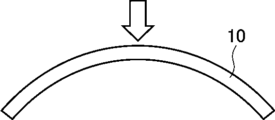
- FIG. 1 shows an example of the optically absorptive anisotropic film of the present invention.
- FIG. 1 is a top view of the optically absorptive anisotropic film
- FIG. 2 is a cross-sectional view taken along line AA of FIG.
- the optically absorptive anisotropic film 10 has a curved shape. More specifically, as shown in Figure 2, the optically absorptive anisotropic film 10 has a shape (convex shape) that is curved in a convex shape toward the upper side of the paper. In other words, the optically absorptive anisotropic film 10 has a convex shape that protrudes on one surface side.
- the optically absorptive anisotropic film 10 has a concave shape with the other surface side recessed.
- Figure 1 shows an embodiment in which the shape of the optically absorptive anisotropic film when viewed in a plane is pentagonal, but the present invention is not limited to this embodiment, and the shape of the optically absorptive anisotropic film when viewed in a plane may be rectangular, circular, or another shape.
- the transmittance central axis angle ⁇ of the optically absorptive anisotropic film of the present invention is 0° or more and 45° or less, preferably 0° or more and less than 45°, and more preferably 0° or more and 35° or less. It is more preferable that the angle be 0° or more and less than 35°, and it is even more preferable that the angle be 0° or more and less than 35°.
- the optically absorptive anisotropic film of the present invention is a film obtained by fixing the alignment state of a liquid crystal composition containing a liquid crystal compound, a dichroic substance, and a compound having a thiol group.
- the components contained in the liquid crystal composition will be described in detail below.
- the liquid crystal composition contains a liquid crystal compound, which can align the dichroic substance with a higher degree of orientation while preventing precipitation of the dichroic substance.
- a liquid crystal compound either a polymer liquid crystal compound or a low molecular weight liquid crystal compound can be used, and the polymer liquid crystal compound is preferred from the viewpoint of increasing the degree of orientation.
- a polymer liquid crystal compound and a low molecular weight liquid crystal compound may be used in combination.
- the term "polymeric liquid crystal compound” refers to a liquid crystal compound having a repeating unit in the chemical structure.
- the term "low molecular weight liquid crystal compound” refers to a liquid crystal compound that does not have a repeating unit in its chemical structure.
- the polymer liquid crystal compound include the thermotropic liquid crystal polymer described in JP-A-2011-237513 and the polymer liquid crystal compound described in paragraphs [0012] to [0042] of WO 2018/199096.
- the low molecular weight liquid crystal compound include the liquid crystal compounds described in paragraphs [0072] to [0088] of JP-A-2013-228706, and among them, liquid crystal compounds exhibiting smectic properties are preferable.
- Such liquid crystal compounds include those described in paragraphs [0019] to [0140] of WO 2022/014340, the descriptions of which are incorporated herein by reference.
- the liquid crystal compound is preferably one that does not exhibit dichroism in the visible light region.
- the content of the liquid crystal compound is preferably 25 to 2000 parts by mass, more preferably 100 to 1300 parts by mass, and even more preferably 200 to 900 parts by mass, relative to 100 parts by mass of the dichroic material described below. When the content of the liquid crystal compound is within the above range, the degree of orientation of the dichroic material is further improved.
- the liquid crystal compound may be contained alone or in combination of two or more. When two or more liquid crystal compounds are contained, the content of the liquid crystal compounds means the total content of the liquid crystal compounds.
- the liquid crystal composition contains a dichroic material.
- the dichroic substance means a dye whose absorbance varies depending on the direction.
- the dichroic material may or may not exhibit liquid crystallinity.
- the dichroic substance is not particularly limited, and examples thereof include visible light absorbing substances (dichroic dyes), luminescent substances (fluorescent substances, phosphorescent substances), ultraviolet absorbing substances, infrared absorbing substances, nonlinear optical substances, carbon nanotubes, and inorganic substances (e.g., quantum rods), and any conventionally known dichroic substance (dichroic dye) can be used.
- a dichroic azo dye compound As the dichroic substance, a dichroic azo dye compound is preferable.
- the dichroic azo dye compound means an azo dye compound whose absorbance varies depending on the direction.
- the dichroic azo dye compound may or may not exhibit liquid crystallinity. When the dichroic azo dye compound exhibits liquid crystallinity, it may exhibit either nematic or smectic properties.
- the temperature range in which the liquid crystal phase is exhibited is preferably room temperature (about 20 to 28°C) to 300°C, and more preferably 50 to 200°C from the viewpoints of handling and manufacturing suitability.
- the dichroic substance a mixture containing at least a dye compound (particularly a dichroic azo dye compound) having a maximum absorption wavelength in the wavelength range of 380 nm or more and less than 455 nm, a dye compound (particularly a dichroic azo dye compound) having a maximum absorption wavelength in the wavelength range of 455 nm or more and less than 560 nm, and a dye compound (particularly a dichroic azo dye compound) having a maximum absorption wavelength in the wavelength range of 560 nm or more and 700 nm or less.
- the dichroic substance preferably has a crosslinkable group.
- the crosslinkable group include cationically polymerizable groups such as an epoxy group, an epoxycyclohexyl group, and an oxetanyl group; and radically polymerizable groups such as an acryloyl group, a methacryloyl group, a vinyl group, a styryl group, and an allyl group.
- the content of the dichroic substance contained in the optically absorptive anisotropic film is not particularly limited, but because the degree of orientation of the optically absorptive anisotropic film formed is high, the content is preferably 3% by mass or more, more preferably 8% by mass or more, even more preferably 10% by mass or more, and particularly preferably 10 to 30% by mass, based on the total mass of the optically absorptive anisotropic film.
- the total amount of the multiple dichroic substances is preferably in the above-mentioned range.
- the content of the dichroic substance contained in the optically absorptive anisotropic film is preferably 20 to 650 mg/cm 3 , more preferably 25 to 500 mg/cm 3 , more preferably 30 to 200 mg/cm 3, and even more preferably 40 to 150 mg/cm 3 , because the degree of orientation of the optically absorptive anisotropic film formed is high.
- the total amount of the multiple dichroic substances is preferably within the above-mentioned range.
- the content (mg/cm 3 ) of the dichroic substance can be obtained by measuring a solution in which a laminate having an optically absorptive anisotropic film is dissolved, or an extract obtained by immersing the laminate in a solvent, by high performance liquid chromatography (HPLC), but is not limited to the above method. Quantification can be performed by using the dichroic substance contained in the optically absorptive anisotropic film as a standard sample.
- One example of a method for calculating the content of the dichroic substance is to calculate the volume by multiplying the thickness of the optically absorptive anisotropic film obtained from a microscopic image of the cross section of the laminate by the area of the optical laminate used to measure the amount of dye, and then dividing the volume by the amount of dye measured by HPLC to calculate the dye content.
- the liquid crystal composition contains a compound having a thiol group (hereinafter, also abbreviated as "thiol compound”).
- thiol compound is not particularly limited as long as it is a compound having one or more thiol groups (-SH) in the molecule.
- the number of thiol groups is not particularly limited, and may be, for example, primary, secondary, or tertiary.
- a thiol group having two hydrogen atoms bonded to the ⁇ -position (referring to the carbon atom to which the thiol group is bonded; the same applies below) is called a primary thiol group, a thiol group having one hydrogen atom bonded to the ⁇ -position is called a secondary thiol group, and a thiol group having no hydrogen atom bonded to the ⁇ -position is called a tertiary thiol group.
- the thiol compound is preferably a compound having two or more primary or secondary thiol groups per molecule, and more preferably a compound having 2 to 4 primary or secondary thiol groups per molecule, because this further suppresses variation in the film thickness of the curved surface portion and the occurrence of cracks.
- the thiol groups in the thiol compound is a secondary thiol group, and it is more preferable that all of the thiol groups present in the molecule of the thiol compound are secondary thiol groups.
- the thiol equivalent of the thiol compound i.e., the mass (g/eq) of the thiol compound equivalent to 1 mol of thiol groups, is preferably 200 or less, more preferably 100 to 200, and even more preferably 100 to 150, in order to further suppress the occurrence of cracks and variations in film thickness on curved surfaces (especially three-dimensional curved surfaces).
- thiol compound examples include: Primary thiol compounds such as 3-mercaptopropionic acid, 2-ethylhexyl-3-mercaptopropionate, methoxybutyl- ⁇ -mercaptopropionate, stearyl-3-mercaptopropionate, ethylene glycol dimercaptopropionate, tetraethylene glycol bis(3-mercaptopropionate), 2,2-bis[[(3-mercaptopropionyl)oxy]methyl]trimethylene bis[3-mercaptopropionate]; Secondary thiol compounds such as pentaerythritol tetrakis(3-mercaptobutyrate), 1,4-bis(3-mercaptobutyryloxy)butane, 1,3,5-tris(2-(3-sulfanylbutanoyloxy)ethyl)-1,3,5-triazinane-2,4,6-trione, and trimethylolpropane tris(3-mercaptobuty
- the content of the thiol group compound is preferably 5 to 15 mass % and more preferably 6 to 12 mass % relative to the total solid mass of the liquid crystal composition.
- the liquid crystal composition preferably contains a vertical alignment agent.
- the vertical alignment agent refers to an additive having a function of aligning the above-mentioned liquid crystal compound in a direction perpendicular to the main plane of the above-mentioned light absorption anisotropic film. Note that "aligning in a vertical direction” does not require alignment at strictly 90°, but means alignment at 70 to 110°.
- vertical alignment agents examples include ionic vertical alignment agents and vertical alignment agents having a boronic acid group, and it is preferable to use an ionic vertical alignment agent and a vertical alignment agent having a boronic acid group in combination.
- an ionic vertical alignment agent for example, an onium compound represented by the following formula (B1) is preferably used.
- ring A represents a quaternary ammonium ion consisting of a nitrogen-containing heterocycle.
- X represents an anion.
- L1 represents a divalent linking group.
- L2 represents a single bond or a divalent linking group.
- Y 1 represents a divalent linking group having a 5- or 6-membered ring as a partial structure.
- Z represents a divalent linking group having an alkylene group having 2 to 20 carbon atoms as a partial structure.
- P1 and P2 each independently represent a monovalent substituent having a polymerizable ethylenically unsaturated bond.
- Ring A represents a quaternary ammonium ion consisting of a nitrogen-containing heterocycle.
- ring A include a pyridine ring, a picoline ring, a 2,2'-bipyridyl ring, a 4,4'-bipyridyl ring, a 1,10-phenanthroline ring, a quinoline ring, an oxazole ring, a thiazole ring, an imidazole ring, a pyrazine ring, a triazole ring, and a tetrazole ring, and are preferably a quaternary imidazolium ion or a quaternary pyridinium ion.
- X represents an anion.
- X include halogen anions (e.g., fluorine ion, chloride ion, bromide ion, iodine ion, etc.), sulfonate ions (e.g., methanesulfonate ion, trifluoromethanesulfonate ion, methylsulfate ion, vinylsulfonate ion, allylsulfonate ion, p-toluenesulfonate ion, p-chlorobenzenesulfonate ion, p-vinylbenzenesulfonate ion, 1,3-benzenedisulfonate ion, 1,5-naphthalenedisulfonate ion, 2,6-naphthalenedisulfonate ion, etc.), sulfate ion, carbonate ion, nitrate ion, thi
- halogen anions sulfonate ions, and hydroxide ions.
- chloride ions bromide ions, iodide ions, methanesulfonate ions, vinylsulfonate ions, p-toluenesulfonate ions, and p-vinylbenzenesulfonate ions are preferred.
- L 1 represents a divalent linking group.
- L 1 include an alkylene group, -O-, -S-, -CO-, -SO 2 -, -NRa- (wherein Ra is an alkyl group having 1 to 5 carbon atoms or a hydrogen atom), an alkenylene group, a divalent linking group having 1 to 20 carbon atoms formed by combining with an alkynylene group or an arylene group.
- L 1 is preferably -AL-, -O-AL-, -CO-O-AL-, or -O-CO-AL- having 1 to 10 carbon atoms, more preferably -AL- or -O-AL- having 1 to 10 carbon atoms, and most preferably -AL- or -O-AL- having 1 to 5 carbon atoms.
- AL represents an alkylene group.
- L2 represents a single bond or a divalent linking group.
- L2 include an alkylene group, -O-, -S-, -CO-, -SO 2 -, -NRa- (wherein Ra is an alkyl group having 1 to 5 carbon atoms or a hydrogen atom), an alkenylene group, a divalent linking group having 1 to 10 carbon atoms formed by combining an alkynylene group or an arylene group, a single bond, -O-, -O-CO-, -CO-O-, -O-AL-O-, -O-AL-O-CO-, -O-AL-CO-O-, -CO-O-AL-O-, -CO-O-AL-O-, -CO-O-AL-O-CO-, -CO-O-AL-CO-, -CO-O-AL-CO-, -CO-O-AL-CO-, -CO-O-AL-CO-O-,
- AL represents an alkylene group.
- L2 is preferably a single bond, -AL-, -O-AL-, or -NRa-AL-O- having 1 to 10 carbon atoms, more preferably a single bond, -AL-, -O-AL-, or -NRa-AL-O- having 1 to 5 carbon atoms, and most preferably a single bond, -O-AL-, or -NRa-AL-O- having 1 to 5 carbon atoms.
- Y1 represents a divalent linking group having a 5- or 6-membered ring as a partial structure.
- Y1 include a cyclohexyl ring, an aromatic ring, or a heterocyclic ring.
- the aromatic ring include a benzene ring, an indene ring, a naphthalene ring, a fluorene ring, a phenanthrene ring, an anthracene ring, a biphenyl ring, and a pyrene ring, and the benzene ring, the biphenyl ring, and the naphthalene ring are particularly preferred.
- the heteroatoms constituting the heterocycle are preferably nitrogen, oxygen and sulfur atoms, and examples thereof include furan ring, thiophene ring, pyrrole ring, pyrroline ring, pyrrolidine ring, oxazole ring, isoxazole ring, thiazole ring, isothiazole ring, imidazole ring, imidazoline ring, imidazolidine ring, pyrazole ring, pyrazoline ring, pyrazolidine ring, triazole ring, furazan ring, tetrazole ring, pyran ring, dioxane ring, dithiane ring, thiine ring, pyridine ring, piperidine ring, oxazine ring, morpholine ring, thiazine ring, pyridazine ring, pyrimidine ring, pyrazine ring, piperazine ring and triazine
- the divalent linking group represented by Y1 is preferably a divalent linking group having two or more 5- or 6-membered rings, and more preferably has a structure in which two or more rings are linked by a linking group.
- Z represents a divalent linking group having an alkylene group having 2 to 20 carbon atoms as a partial structure, and consisting of a combination of -O-, -S-, -CO-, and -SO2-, and the alkylene group may have a substituent.
- the divalent linking group include an alkyleneoxy group and a polyalkyleneoxy group.
- the number of carbon atoms in the alkylene group represented by Z is more preferably 2 to 16, even more preferably 2 to 12, and particularly preferably 2 to 8.
- P1 and P2 each independently represent a monovalent substituent having a polymerizable ethylenically unsaturated group.
- Examples of the monovalent substituent having the above polymerizable ethylenically unsaturated group include the following formulae (M-1) to (M-8). That is, the monovalent substituent having a polymerizable ethylenically unsaturated group may be a substituent consisting of only an ethenyl group, as in (M-8).
- R represents a hydrogen atom or an alkyl group, preferably a hydrogen atom or a methyl group.
- R represents a hydrogen atom or an alkyl group, preferably a hydrogen atom or a methyl group.
- P1 is preferably (M-1).
- P2 is preferably (M-1) or (M-8), and in compounds in which ring A is a quaternary imidazolium ion, P2 is preferably (M-8) or (M-1), and in compounds in which ring A is a quaternary pyridinium ion, P2 is preferably (M-1).
- Examples of the onium compound represented by the above formula (B1) include the onium salts described in paragraphs 0052 to 0058 of JP-A-2012-208397, the onium salts described in paragraphs 0024 to 0055 of JP-A-2008-026730, and the onium salts described in JP-A-2002-37777.
- examples of ionic vertical alignment agents include those described in paragraphs [0017] to [0029] of JP2020-181150A.
- a suitable example of the vertical alignment agent having a boronic acid group is a boronic acid compound represented by the following formula (B2).
- R1 and R2 each independently represent a hydrogen atom, an optionally substituted aliphatic hydrocarbon group, an optionally substituted aryl group, or an optionally substituted heterocyclic group. Furthermore, R3 represents a substituent.
- Examples of the aliphatic hydrocarbon group represented by one embodiment of R1 and R2 include a substituted or unsubstituted linear or branched alkyl group having 1 to 20 carbon atoms (e.g., a methyl group, an ethyl group, an isopropyl group, etc.), a substituted or unsubstituted cyclic alkyl group having 3 to 20 carbon atoms (e.g., a cyclohexyl group, etc.), and an alkenyl group having 2 to 20 carbon atoms (e.g., a vinyl group, etc.).
- a substituted or unsubstituted linear or branched alkyl group having 1 to 20 carbon atoms e.g., a methyl group, an ethyl group, an isopropyl group, etc.
- a substituted or unsubstituted cyclic alkyl group having 3 to 20 carbon atoms e.g., a cyclo
- Examples of the aryl group represented by one embodiment of R 1 and R 2 include a substituted or unsubstituted phenyl group having 6 to 20 carbon atoms (e.g., a phenyl group, a tolyl group, etc.), a substituted or unsubstituted naphthyl group having 10 to 20 carbon atoms, and the like.
- examples of the heterocyclic group represented by one embodiment of R1 and R2 include substituted or unsubstituted 5- or 6-membered ring groups containing at least one heteroatom (e.g., a nitrogen atom, an oxygen atom, a sulfur atom, etc.), and specific examples thereof include a pyridyl group, an imidazolyl group, a furyl group, a piperidyl group, and a morpholino group.
- R 1 and R 2 may be linked to each other to form a ring; for example, the isopropyl groups of R 1 and R 2 may be linked to form a 4,4,5,5-tetramethyl-1,3,2-dioxaborolane ring.
- R 1 and R 2 are preferably a hydrogen atom, a linear or branched alkyl group having 1 to 3 carbon atoms, or a ring formed by combining these, and more preferably a hydrogen atom.
- the substituent represented by R3 is preferably a substituent containing a functional group capable of bonding to a (meth)acrylic group.
- the functional group capable of bonding to the (meth)acrylic group include a vinyl group, an acrylate group, a methacrylate group, an acrylamide group, a styryl group, a vinyl ketone group, a butadiene group, a vinyl ether group, an oxiranyl group, an aziridinyl group, and an oxetane group.
- a vinyl group, an acrylate group, a methacrylate group, a styryl group, an oxiranyl group, or an oxetane group is preferred, and a vinyl group, an acrylate group, an acrylamide group, or a styryl group is more preferred.
- R3 is preferably a substituted or unsubstituted aliphatic hydrocarbon group, aryl group or heterocyclic group having a functional group capable of bonding to a (meth)acrylic group.
- the aliphatic hydrocarbon group include substituted or unsubstituted linear or branched alkyl groups having 1 to 30 carbon atoms (e.g., methyl, ethyl, isopropyl, n-propyl, butyl, pentyl, hexyl, heptyl, octyl, nonyl, decyl, undecyl, dodecyl, tridecyl, hexadecyl, octadecyl, eicosyl, isopropyl, isobutyl, sec-butyl, tert-butyl, butyl group, isopentyl group, neopentyl group, 1-methylbutyl group, isohe
- aryl group examples include substituted or unsubstituted phenyl groups having 6 to 50 carbon atoms (e.g., a phenyl group, a tolyl group, a styryl group, a 4-benzoyloxyphenyl group, a 4-phenoxycarbonylphenyl group, a 4-biphenyl group, a 4-(4-octyloxybenzoyloxy)phenoxycarbonylphenyl group, etc.), and substituted or unsubstituted naphthyl groups having 10 to 50 carbon atoms (e.g., an unsubstituted naphthyl group, etc.).
- substituted or unsubstituted phenyl groups having 6 to 50 carbon atoms e.g., a phenyl group, a tolyl group, a styryl group, a 4-benzoyloxyphenyl group, a 4-phenoxycarbonylphenyl group, a
- heterocyclic groups include substituted or unsubstituted 5- or 6-membered ring groups containing at least one heteroatom (e.g., a nitrogen atom, an oxygen atom, a sulfur atom, etc.), and examples thereof include pyrrole, furan, thiophene, pyrazole, imidazole, triazole, oxazole, isoxazole, oxadiazole, thiazole, thiadiazole, indole, carbazole, benzofuran, dibenzofuran, thianaphthene, dibenzothiophene, indazole benzimidazole, anthranil, benzisoxazole, benzoxazole, benzothiazole, purine, pyridine, pyridazine, pyrimidine, pyrazine, triazine, quinoline, acridine, isoquinoline, phthalazine, quinazoline, quinoxaline,
- Examples of the boronic acid compound represented by the above formula (B2) include the boronic acid compounds represented by general formula (I) described in paragraphs 0023 to 0032 of JP-A No. 2008-225281. As the compound represented by the above formula (B2), the compounds exemplified below are also preferred.
- the content of any vertical alignment agent contained in the optically absorptive anisotropic film is preferably 1.0 to 7.0 parts by mass, more preferably 1.5 to 8.0 parts by mass, and even more preferably 2.5 to 6.0 parts by mass, per 100 parts by mass of the liquid crystal compound.
- the vertical alignment agent may be contained alone or in combination of two or more. When two or more liquid crystal compounds are contained, the content of the vertical alignment agent means the total content of the vertical alignment agents.
- the liquid crystal composition preferably contains a solvent.
- the solvent include ketones (e.g., acetone, 2-butanone, methyl isobutyl ketone, cyclopentanone, cyclohexanone, acetylacetone, etc.), ethers (e.g., dioxane, tetrahydrofuran, tetrahydropyran, dioxolane, tetrahydrofurfuryl alcohol, cyclopentyl methyl ether, dibutyl ether, etc.), aliphatic hydrocarbons (e.g., hexane, etc.), alicyclic hydrocarbons (e.g., cyclohexane, etc.), aromatic hydrocarbons (e.g., benzene, toluene, xylene, tetralin, trimethylbenzene, etc.), halogenated carbons (e.g.
- ketones e.g., acetone, 2-
- the content of the solvent is preferably 60 to 99.5% by mass, more preferably 70 to 99% by mass, and particularly preferably 75 to 98% by mass, relative to the total mass (100% by mass) of the liquid crystal composition.
- the liquid crystal composition may contain a polymerization initiator.
- the polymerization initiator is not particularly limited, but is preferably a compound having photosensitivity, that is, a photopolymerization initiator.
- a photopolymerization initiator various compounds can be used without any particular limitation. Examples of the photopolymerization initiator include ⁇ -carbonyl compounds (see U.S. Pat. Nos. 2,367,661 and 2,367,670), acyloin ethers (see U.S. Pat. No. 2,448,828), ⁇ -hydrocarbon-substituted aromatic acyloin compounds (see U.S. Pat. No.
- o-acyloxime compounds JP 2016-27384 A [0065]
- acylphosphine oxide compounds JP 63-40799 A, JP 5-29234 A, JP 10-95788 A and JP 10-29997 A.
- commercially available products can be used, such as Irgacure-184, Irgacure-907, Irgacure-369, Irgacure-651, Irgacure-819, Irgacure-OXE-01, and Irgacure-OXE-02, all of which are manufactured by BASF.
- the content of the polymerization initiator is preferably 0.01 to 30% by mass, and more preferably 0.1 to 15% by mass, based on the total solid mass of the liquid crystal composition.
- the liquid crystal composition may contain an interface modifier.
- the interfacial improver is not particularly limited, and a polymer-based interfacial improver or a low molecular weight interfacial improver can be used.
- the compounds described in paragraphs [0253] to [0293] of JP2011-237513A can be used.
- the interface improver fluorine (meth)acrylate polymers described in, for example, paragraphs [0018] to [0043] of JP-A-2007-272185 can also be used.
- Examples of the interface improver include compounds described in paragraphs [0079] to [0102] of JP-A-2007-069471, polymerizable liquid crystal compounds represented by formula (4) described in JP-A-2013-047204 (particularly compounds described in paragraphs [0020] to [0032]), polymerizable liquid crystal compounds represented by formula (4) described in JP-A-2012-211306 (particularly compounds described in paragraphs [0022] to [0029]), and liquid crystal alignment promoters represented by formula (4) described in JP-A-2002-129162 (particularly compounds described in paragraphs [0032] to [0040]).
- the content of the interfacial modifier is preferably 0.005 to 15% by mass, more preferably 0.01 to 5% by mass, and even more preferably 0.015 to 3% by mass, based on the total solid mass of the liquid crystal composition.
- the total amount of the multiple interfacial modifiers is within the above-mentioned range.
- the method for forming the optically absorptive anisotropic film is not particularly limited, and examples of the method include a method including, in this order, a step of applying the above-mentioned liquid crystal composition (hereinafter also referred to as "composition for forming an optically absorptive anisotropic film") to form a coating film (hereinafter also referred to as “coating film forming step"), and a step of orienting the liquid crystal component and dichroic material contained in the coating film (hereinafter also referred to as "orientation step”).
- the liquid crystal component is a component including not only the above-mentioned liquid crystal compound but also a dichroic substance having liquid crystal properties when the above-mentioned dichroic substance has liquid crystal properties.
- the coating film forming step is a step of forming a coating film by applying a composition for forming an optically absorptive anisotropic film.
- a composition for forming an optically absorptive anisotropic film that contains the above-mentioned solvent or by using a composition for forming an optically absorptive anisotropic film that has been made into a liquid such as a molten liquid by heating or the like, it becomes easy to apply the composition for forming an optically absorptive anisotropic film.
- compositions for forming an optically absorptive anisotropic film include known methods such as roll coating, gravure printing, spin coating, wire bar coating, extrusion coating, direct gravure coating, reverse gravure coating, die coating, spraying, and inkjet printing.
- the coating amount of the dichroic substance in the coating film forming step is preferably 15 mg/m2 or more , more preferably 50 to 1000 mg/ m2 , and even more preferably 200 to 800 mg/ m2 .
- the alignment step is a step for aligning the liquid crystal component contained in the coating film, thereby obtaining a light absorbing anisotropic film.
- the orientation step may include a drying treatment. By the drying treatment, components such as a solvent can be removed from the coating film.
- the drying treatment may be performed by leaving the coating film at room temperature for a predetermined time (for example, natural drying), or may be performed by heating and/or blowing air.
- the liquid crystal component contained in the composition for forming an optically absorptive anisotropic film may be aligned by the above-mentioned coating film forming process or drying treatment.
- the coating film is dried to remove the solvent from the coating film, thereby obtaining a coating film having optical absorption anisotropy (i.e., an optically absorptive anisotropic film).
- the drying treatment is carried out at a temperature equal to or higher than the transition temperature of the liquid crystal component contained in the coating film to a liquid crystal phase, the heating treatment described below does not need to be carried out.
- the transition temperature of the liquid crystal component contained in the coating film to the liquid crystal phase is preferably 10 to 250°C, more preferably 25 to 190°C, from the viewpoint of manufacturability, etc. If the transition temperature is 10°C or higher, no cooling process or the like is required to lower the temperature to the temperature range in which the liquid crystal phase is exhibited, and this is preferable. Also, if the transition temperature is 250°C or lower, a high temperature is not required even when the film is once in an isotropic liquid state at a temperature higher than the temperature range in which the liquid crystal phase is exhibited, and this is preferable, since it is possible to reduce the waste of thermal energy and the deformation and deterioration of the substrate.
- the alignment step preferably includes a heat treatment, which allows the liquid crystal component contained in the coating film to be aligned, so that the coating film after the heat treatment can be suitably used as an optically absorptive anisotropic film.
- the heat treatment is preferably performed at 10 to 250° C., more preferably 25 to 190° C.
- the heating time is preferably 1 to 300 seconds, more preferably 1 to 60 seconds.
- the alignment step may include a cooling treatment carried out after the heating treatment.
- the cooling treatment is a treatment for cooling the coated film after heating to about room temperature (20 to 25°C). This makes it possible to fix the alignment of the liquid crystal component contained in the coated film.
- the cooling means is not particularly limited and can be carried out by a known method. By the above steps, an optically absorptive anisotropic film can be obtained.
- the method for aligning the liquid crystal component contained in the coating film includes drying treatment and heating treatment, but is not limited thereto and can be carried out by any known alignment treatment.
- the method for forming an optically absorptive anisotropic film may include a step of curing the optically absorptive anisotropic film (hereinafter also referred to as a "curing step") after the above-mentioned alignment step.
- the curing step is carried out, for example, by heating and/or light irradiation (exposure) when the optically absorptive anisotropic film has a crosslinkable group (polymerizable group).
- the curing step is preferably carried out by light irradiation.
- the light source used for curing may be various light sources such as infrared light, visible light, or ultraviolet light, but ultraviolet light is preferred.
- ultraviolet light may be irradiated while heating during curing, or ultraviolet light may be irradiated through a filter that transmits only specific wavelengths.
- the heating temperature during exposure is preferably 25 to 140° C., although it depends on the transition temperature to a liquid crystal phase of the liquid crystal component contained in the liquid crystal film.
- the exposure may be carried out under a nitrogen atmosphere.
- the curing of the liquid crystal film proceeds by radical polymerization, it is preferable to carry out the exposure under a nitrogen atmosphere, since this reduces the inhibition of polymerization caused by oxygen.
- the thickness of the optically absorptive anisotropic film is not particularly limited, but is preferably 1.5 ⁇ m or more, more preferably 2 to 10 ⁇ m, and even more preferably 2 to 8 ⁇ m, because this can improve the light-shielding property in oblique directions and increase the degree of orientation of the optically absorptive anisotropic film.
- the thickness of the optically absorptive anisotropic film is measured by cutting the film with a microtome to prepare a cross-section of the film, and then observing the cross-section with a scanning electron microscope from the normal direction to the cross-section.
- the difference in the degree of orientation of the optically absorptive anisotropic film at wavelengths of 450 nm, 550 nm and 650 nm is preferably 0.025 or less, more preferably 0.020 or less, and even more preferably 0.010 or less.
- the degrees of orientation of the optically absorptive anisotropic film at wavelengths of 450 nm, 550 nm and 650 nm are calculated by the following method.
- the Mueller matrix is measured at 5° intervals in the polar angle range of ⁇ 70° to 70° in the in-plane slow axis direction, and kx( ⁇ ), ky( ⁇ ), and kz( ⁇ ) are determined by fitting.
- the absorption anisotropies Ao( ⁇ ) and Ae( ⁇ ) are determined according to the following formulas (A) to (D), and the degree of orientation S is calculated according to the following formula (E).
- the difference in the degree of orientation (0.025 or less) specified in the above-mentioned requirement 3 refers to the maximum difference among the difference in the degree of orientation at wavelengths of 450 nm and 550 nm, the difference in the degree of orientation at wavelengths of 450 nm and 650 nm, and the difference in the degree of orientation at wavelengths of 550 nm and 650 nm.
- the degree of orientation of the optically absorptive anisotropic film at a wavelength of 550 nm is preferably 0.94 or more, more preferably 0.95 to 1.00, and even more preferably 0.96 to 1.00.
- the degree of orientation of the optically absorptive anisotropic film at a wavelength of 550 nm can be calculated by the above-mentioned method.
- the heat treatment in the above-mentioned orientation step multiple times (particularly twice) because this makes it easier to make the difference in the degree of orientation of the optically absorptive anisotropic film at wavelengths of 450 nm, 550 nm and 650 nm 0.025 or less.
- the cooling treatment carried out between the two heat treatments is preferably a treatment for cooling the coating film after the first heat treatment to about 30 to 45°C.
- the haze value of the optically absorptive anisotropic film is preferably 0.3% or less, more preferably 0.2% or less, and even more preferably 0.1% or less, because this maintains a high degree of polarization of light passing through the optically absorptive anisotropic film and results in more favorable optical performance.
- the haze value herein refers to the haze measured in accordance with JIS K7136:2000 "Method of determining haze for plastics - transparent materials", and refers to the value measured using a haze meter (e.g., NDH2000 (manufactured by Nippon Denshoku Industries Co., Ltd.)) in an environment of 25°C and relative humidity of 55%.
- the heat treatment in the above-mentioned orientation process multiple times (particularly twice) because this makes it easier to adjust the haze ratio of the optically absorptive anisotropic film to 0.3% or less.
- the laminate of the present invention has the above-mentioned optically absorptive anisotropic film of the present invention.
- the laminate of the present invention may have at least one layer selected from the group consisting of a polarizer layer, an antireflection layer, and a retardation layer.
- the polarizer layer is not particularly limited as long as it is a member having a function of converting light into a specific linearly polarized light, and a conventionally known absorptive polarizer and reflective polarizer can be used.
- the absorption-type polarizer include an iodine-based polarizer, a dye-based polarizer using a dichroic dye, a polyene-based polarizer, etc.
- the iodine-based polarizer and the dye-based polarizer include a coating-type polarizer and a stretching-type polarizer, and although either can be used, the coating-type polarizer is preferable.
- a polarizer by stretching and dyeing a laminated film in which a polyvinyl alcohol layer is formed on a substrate are described in Japanese Patent No. 5,048,120, Japanese Patent No. 5,143,918, Japanese Patent No. 4,691,205, Japanese Patent No. 4,751,481, and Japanese Patent No. 4,751,486, and these known techniques related to polarizers can also be preferably used.
- coating-type polarizers include those described in WO2018/124198, WO2018/186503, WO2019/132020, WO2019/132018, WO2019/189345, JP2019-197168A, JP2019-194685A, and JP2019-139222A. These known techniques related to polarizers can also be preferably used.
- a polarizer in which thin films with different birefringence are laminated a wire grid type polarizer, a polarizer in which a cholesteric liquid crystal having a selective reflection region is combined with a quarter-wave plate, and the like are used.
- a polarizer containing a polyvinyl alcohol resin a polymer containing --CH 2 --CHOH-- as a repeating unit; in particular, at least one selected from the group consisting of polyvinyl alcohol and an ethylene-vinyl alcohol copolymer
- the polarizer may have depolarizing portions formed along the opposing edges.
- the depolarizing portions include those described in JP2014-240970A.
- the polarizer may have non-polarizing portions arranged at a predetermined interval in the longitudinal direction and/or width direction.
- the non-polarizing portions are partially bleached portions.
- the arrangement pattern of the non-polarizing portions may be appropriately set depending on the purpose. For example, the non-polarizing portions are arranged at positions corresponding to the camera portion of the image display device when the polarizer is cut (cut, punched, etc.) to a predetermined size in order to attach it to an image display device of a predetermined size. Examples of the arrangement pattern of the non-polarizing portions include those described in JP 2016-27392 A.
- the antireflection layer is not particularly limited, and any known antireflection layer can be used.
- Examples of the antireflection layer include the antireflection layers described in paragraphs 0108 to 0121 of International Publication No. WO 2016/047648, the contents of which are incorporated herein by reference.
- the retardation layer is not particularly limited, and a known retardation layer can be used.
- the retardation layer include a stretched polycarbonate film, a stretched norbornene-based polymer film, a transparent film containing and oriented inorganic particles having birefringence such as strontium carbonate, a thin film formed by obliquely depositing an inorganic dielectric on a support, and a film in which a liquid crystal compound is uniaxially aligned and fixed in orientation.
- a film in which the above-mentioned liquid crystal compound is uniaxially aligned and fixed is preferable.
- the image display device of the present invention is an image display device having the laminate of the present invention.
- the display element used in the image display device of the present invention is not particularly limited, and examples thereof include a liquid crystal cell, an organic EL display panel, an inorganic EL display panel, and a plasma display panel.
- the manufacturing method for producing the laminate of the present invention is not particularly limited.
- the manufacturing method according to the first aspect includes a method for manufacturing a laminate, the method including: an optically absorbing anisotropic film-forming step of forming an optically absorbing anisotropic film on a temporary support, the optically absorbing anisotropic film being formed by fixing the alignment state of a liquid crystal composition containing a liquid crystal compound, a dichroic substance, and a compound having a thiol group, the angle ⁇ between the central axis of transmittance of the film and the normal direction to the film surface being 0° C.
- the manufacturing method according to the first aspect is a method in which, except for using a liquid crystal composition containing the above-mentioned thiol compound, a laminate having a support and an optically absorptive anisotropic film is produced by a conventionally known method, and then the optically absorptive anisotropic film is pressed against a mold having a curved portion, thereby forming a curved portion in the optically absorptive anisotropic film.
- an example of a manufacturing method is a method for manufacturing a laminate, which includes a light absorbing anisotropic film formation step of forming a light absorbing anisotropic film on a support having a curved surface, the light absorbing anisotropic film being formed by fixing the orientation state of a liquid crystal composition containing a liquid crystal compound, a dichroic substance, and a compound having a thiol group, and in which the angle ⁇ between the central axis of transmittance of the film and the normal direction to the film surface is 0° C. or more and 45° or less.
- the manufacturing method according to the first aspect is a method similar to the conventionally known methods (e.g., the above-mentioned coating film formation process and alignment process) except that a support having a curved surface and a liquid crystal composition containing the above-mentioned thiol compound are used.
- the optical device of the present invention is an optical device having an optical filter including the above-mentioned laminate of the present invention, and a light guide plate having a diffraction element disposed on the surface thereof.
- a head mounted display according to the present invention includes the above-mentioned optical device and an image display element.
- Example 1 Temporary Support A cellulose acylate film 1 (TAC substrate having a thickness of 40 ⁇ m; TG40, Fuji Photo Film Co., Ltd.) was used as a temporary support after the surface thereof was saponified with an alkaline solution.
- TAC substrate having a thickness of 40 ⁇ m; TG40, Fuji Photo Film Co., Ltd.
- composition for forming alignment film 1 ⁇ 10.0 parts by weight of the polymer PA-1 shown below; 0.83 parts by weight of the acid generator PAG-1 shown below; 0.06 parts by weight of the stabilizer DIPEA shown below; 100 parts by weight of butyl acetate --- ---------------------------------------------------------------------------------------------------------------------------------------------------------------------------------------------------------------------------------------------------------------------------------------------------------------------------------------------------------------------------------------------------------------------------------------------------------------------------------------------------------------------------------------------------------------------------------
- composition 1 for forming an optically absorbent anisotropic film having the following composition was applied with a wire bar, heated at 120° C. for 60 seconds, and then cooled to 35° C. Next, it was heated at 75° C. for 60 seconds, and cooled again to room temperature.
- an LED (light emitting diode) lamp (center wavelength 365 nm) was used to irradiate the film normal direction at an illuminance of 200 mW/ cm2 for 2 seconds to produce an optically absorptive anisotropic film 1 on the alignment film.
- the optically absorptive anisotropic film 1 had a thickness of 4.5 ⁇ m.
- the transmittance central axis angle ⁇ of the produced optically absorptive anisotropic layer 1 was measured by the method described above. The results are shown in Table 1 below.
- Optically absorptive anisotropic film-forming composition 1 ⁇ 0.69 parts by weight of the dichroic substance D-1 shown below 0.17 parts by weight of the dichroic substance D-2 shown below 1.13 parts by weight of the dichroic substance D-3 shown below Polymer liquid crystal compound P- 1 8.67 parts by weight; Liquid crystal compound L-1 shown below 1.97 parts by weight; IRGACUE OXE-2 (manufactured by BASF) 0.20 parts by weight; Vertical alignment agent E-1 shown below 0.16 parts by weight; Agent E-2 0.16 parts by mass; thiol compound (EHMP, manufactured by SC Organic Chemicals Co., Ltd.) 0.407 parts by mass; surfactant F-1 (below) 0.007 parts by mass; cyclopentanone 78.17 parts by mass Benzyl alcohol 8.69 parts by mass---------------------------------------------------------------------------------------------------------------------------------------------
- Liquid crystal compound L-1 [a mixture of the following liquid crystal compounds (RA), (RB), and (RC) in a mass ratio of 84:14:2]
- an LED lamp (center wavelength 365 nm) was used to irradiate the film normal direction at an illuminance of 200 mW/ cm2 for 2 seconds to form a protective layer 1 on the optically absorbing anisotropic film 1, thereby producing an optically absorbing anisotropic film 1 (layer structure: temporary support 1/alignment film 1/optically absorbing anisotropic film 1/protective layer 1).
- the thickness of the protective layer 1 was 0.5 ⁇ m.
- Coating solution for forming protective layer 1 ⁇ 3.80 parts by weight of modified polyvinyl alcohol PVA-1 shown below; 0.20 parts by weight of IRGACURE 2959 (manufactured by BASF); 0.08 parts by weight of dye compound G-1 shown below; 70 parts by weight of water; 30 parts by weight of methanol --- ------------------------------------------------------------------------------------------------------------------------------------------------------------------------------------------------------------------------------------------------------------------------------------------------------------------------------------------------------------------------------------------------------------------------------------------------------------------------------------------------------------------------------------
- the protective layer 1 side of the light-absorbing anisotropic film 1 (layer structure: temporary support 1/alignment film 1/light-absorbing anisotropic film 1/protective layer 1) was attached to a PMMA film via an adhesive sheet, and only the temporary support was peeled off to form the light-absorbing anisotropic film 2, which was then set in a molding device. At this time, the PMMA side was arranged to be on the upper side.
- the molding space in the molding device consists of a box 1 and a box 2 partitioned by the light-absorbing anisotropic film 2, and in the box 1 below the light-absorbing anisotropic film 2, a mold was prepared that imitates the surface shape of a smartphone cover glass (size: 65 mm x 140 mm, minimum radius of curvature of the three-dimensional curved surface of the round edge part: 38 mm, minimum radius of curvature of the developable surface of the round edge part: 38 mm) and was arranged so that the curved surface of the round edge part was on top.
- a smartphone cover glass size: 65 mm x 140 mm, minimum radius of curvature of the three-dimensional curved surface of the round edge part: 38 mm, minimum radius of curvature of the developable surface of the round edge part: 38 mm
- a transparent window was provided at the top of the box 2 above the light absorptive anisotropic film 2, and an IR light source for heating the light absorptive anisotropic film 2 was provided outside the window.
- the inside of box 1 and the inside of box 2 were evacuated to a vacuum of 0.1 atmosphere or less using a vacuum pump.
- the light-absorptive anisotropic film 2 was irradiated with infrared rays and heated until the temperature of the light-absorptive anisotropic film 2 reached 108°C.
- Example 2 Example 1 was repeated to prepare a laminate 2, except that the composition 1 for forming an optically absorptive anisotropic film was replaced with the composition 2 for forming an optically absorptive anisotropic film having the following composition.
- Example 3 A laminate 3 was prepared in the same manner as in Example 1, except that the composition 1 for forming an optically absorptive anisotropic film was replaced with the composition 3 for forming an optically absorptive anisotropic film having the following composition.
- Example 4 A laminate 4 was prepared in the same manner as in Example 1, except that the optically absorptive anisotropic film-forming composition 1 was replaced with an optically absorptive anisotropic film-forming composition 4 having the following composition.
- ⁇ Optically absorptive anisotropic film-forming composition 4 ⁇ - 0.69 parts by mass of the dichroic material D-1 - 0.17 parts by mass of the dichroic material D-2 - 1.13 parts by mass of the dichroic material D-3 - 8.67 parts by mass of the polymer liquid crystal compound P-1 - 1.97 parts by mass of the liquid crystal compound L-1 - 0.20 parts by mass of IRGACUE OXE-2 (manufactured by BASF) - 0.16 parts by mass of the vertical alignment agent E-1 - 0.16 parts by mass of the vertical alignment agent E-2 - 0.407 parts by mass of a thiol compound (PEMP, manufactured by SC Organic Chemicals Co., Ltd.) - 0.007 parts by mass of the
- Example 5 Example 1 was repeated to prepare a laminate 5, except that the composition 1 for forming an optically absorptive anisotropic film was replaced with the composition 5 for forming an optically absorptive anisotropic film having the following composition.
- Example 6 A laminate 6 was prepared in the same manner as in Example 1, except that the composition 1 for forming an optically absorptive anisotropic film was replaced with the composition 6 for forming an optically absorptive anisotropic film having the following composition.
- Example 7 Example 1 was repeated to prepare a laminate 7, except that the composition 1 for forming an optically absorptive anisotropic film was replaced with the composition 7 for forming an optically absorptive anisotropic film having the following composition.
- Laminate 8 was produced in the same manner as in Example 7, except that the mold used for processing the curved surface of the lightly absorptive anisotropic film was changed to a concave lens (diameter: 50 nm ⁇ , radius of curvature: 52 mm).
- Example 9 The composition 1 for forming an alignment film of Example 1 was applied to the surface of a concave lens (diameter: 50 nm ⁇ , radius of curvature: 52 mm) using a spin coater. After application, the lens was dried with hot air at 145° C. for 120 seconds to form an alignment film. The thickness of the alignment film was 0.5 ⁇ m. Next, the composition 7 for forming an optically absorptive anisotropic film of Example 7 was applied onto the formed alignment film by a spin coater, heated at 120° C. for 60 seconds, and then cooled to 35° C. Then, it was heated at 75° C. for 60 seconds, and cooled again to room temperature.
- an LED lamp (center wavelength 365 nm) was used to irradiate the alignment film from directly above at an illuminance of 200 mW/ cm2 for 2 seconds to produce an optically absorptive anisotropic film on the alignment film.
- the optically absorptive anisotropic film had a thickness of 4.5 ⁇ m.
- the surface of the obtained optically absorptive anisotropic film was subjected to a corona treatment under conditions of 4.0 m/min, 440 W, and a clearance of 2.0 mm, and then the protective layer forming coating solution 1 of Example 1 was applied thereto by a spin coater.
- the support on which the coating film was formed was dried with hot air at 60° C. for 60 seconds and then with hot air at 100° C. for 120 seconds to form a protective layer. Thereafter, under nitrogen purging conditions (oxygen concentration 100 ppm or less), a protective layer was formed by irradiating the laminate with an LED lamp (center wavelength 365 nm) from directly above at an illuminance of 200 mW/ cm2 for 2 seconds to produce a laminate.
- the protective layer had a thickness of 0.5 ⁇ m.
- Example 10 A laminate 10 was prepared in the same manner as in Example 1, except that the composition 1 for forming an optically absorptive anisotropic film was replaced with a composition 10 for forming an optically absorptive anisotropic film having the following composition.
- Example 11 A laminate 11 was prepared in the same manner as in Example 1, except that the composition 1 for forming an optically absorptive anisotropic film was replaced with a composition 11 for forming an optically absorptive anisotropic film having the following composition.
- Example 12 A laminate 12 was prepared in the same manner as in Example 1, except that the optically absorptive anisotropic film-forming composition 1 was replaced with an optically absorptive anisotropic film-forming composition 12 having the following composition.
- ⁇ Optically absorptive anisotropic film-forming composition 12 ⁇ - 0.78 parts by mass of the dichroic material D-4 - 0.21 parts by mass of the dichroic material D-5 - 1.39 parts by mass of the dichroic material D-6 - 7.39 parts by mass of the liquid crystal compound L-2 - 2.46 parts by mass of the liquid crystal compound L-3 - 0.71 parts by mass of IRGACUE 369 (manufactured by BASF) - 0.828 parts by mass of a thiol compound (Karenz MT TPMB, manufactured by Resonac Co., Ltd.) - 0.036 parts by mass of BYK-361N (BYK-Chemie) - 87.02 parts by mass of o
- Example 1 A laminate H1 was prepared in the same manner as in Example 1, except that the thiol compound was not blended in the optically absorptive anisotropic film-forming composition 1.
- Example 1 a comparison of Examples 1 to 4 revealed that when the thiol compound has two or more primary or secondary thiol groups in one molecule, the variation in film thickness at the curved surface portion and the occurrence of cracks are further suppressed.
- Example 3 reveals that when at least one of the thiol groups in the thiol compound is a secondary thiol group, the storage stability of the liquid crystal composition becomes good. Comparing Example 1 with Example 2, it was found that when the thiol equivalent of the thiol compound is 200 or less, the occurrence of cracks on curved surfaces (especially three-dimensional curved surfaces) and variations in film thickness are further suppressed.
- Example 6 Comparing Example 6 with Example 7, it was found that when the content of the thiol group compound is 5 to 15 mass % relative to the total mass of the optically absorptive anisotropic film, the film thickness variation and the occurrence of cracks can be further suppressed, while at the same time, the degree of orientation of the dichroic dye can be maintained high.
Landscapes
- Physics & Mathematics (AREA)
- Nonlinear Science (AREA)
- General Physics & Mathematics (AREA)
- Optics & Photonics (AREA)
- Chemical & Material Sciences (AREA)
- Crystallography & Structural Chemistry (AREA)
- Mathematical Physics (AREA)
- Spectroscopy & Molecular Physics (AREA)
- Polarising Elements (AREA)
Priority Applications (2)
| Application Number | Priority Date | Filing Date | Title |
|---|---|---|---|
| JP2025535618A JPWO2025022843A1 (https=) | 2023-07-26 | 2024-06-10 | |
| US19/426,106 US20260110912A1 (en) | 2023-07-26 | 2025-12-19 | Light absorption anisotropic film, laminate, optical device, and head-mounted display |
Applications Claiming Priority (2)
| Application Number | Priority Date | Filing Date | Title |
|---|---|---|---|
| JP2023-121521 | 2023-07-26 | ||
| JP2023121521 | 2023-07-26 |
Related Child Applications (1)
| Application Number | Title | Priority Date | Filing Date |
|---|---|---|---|
| US19/426,106 Continuation US20260110912A1 (en) | 2023-07-26 | 2025-12-19 | Light absorption anisotropic film, laminate, optical device, and head-mounted display |
Publications (1)
| Publication Number | Publication Date |
|---|---|
| WO2025022843A1 true WO2025022843A1 (ja) | 2025-01-30 |
Family
ID=94374237
Family Applications (1)
| Application Number | Title | Priority Date | Filing Date |
|---|---|---|---|
| PCT/JP2024/021066 Pending WO2025022843A1 (ja) | 2023-07-26 | 2024-06-10 | 光吸収異方性膜、積層体、光学装置およびヘッドマウントディスプレイ |
Country Status (3)
| Country | Link |
|---|---|
| US (1) | US20260110912A1 (https=) |
| JP (1) | JPWO2025022843A1 (https=) |
| WO (1) | WO2025022843A1 (https=) |
Citations (7)
| Publication number | Priority date | Publication date | Assignee | Title |
|---|---|---|---|---|
| JP2019215404A (ja) * | 2018-06-11 | 2019-12-19 | Jnc株式会社 | 重合性液晶組成物、その液晶重合膜、位相差フィルム、偏光板および表示素子 |
| JP2021002026A (ja) * | 2019-06-21 | 2021-01-07 | Dic株式会社 | 重合性液晶組成物、光学異方体及びその製造方法 |
| WO2021111861A1 (ja) * | 2019-12-02 | 2021-06-10 | 富士フイルム株式会社 | 積層体、光学装置および表示装置 |
| WO2021131792A1 (ja) * | 2019-12-26 | 2021-07-01 | 富士フイルム株式会社 | 光吸収異方性層、積層体、光学フィルム、画像表示装置、バックライトモジュール |
| WO2021145446A1 (ja) * | 2020-01-15 | 2021-07-22 | 富士フイルム株式会社 | 光学システム |
| WO2021187379A1 (ja) * | 2020-03-19 | 2021-09-23 | 富士フイルム株式会社 | 液晶表示装置 |
| JP2021147410A (ja) * | 2020-03-16 | 2021-09-27 | Jnc株式会社 | 重合性液晶化合物、重合性液晶組成物、液晶重合膜類、偏光板、および表示素子 |
-
2024
- 2024-06-10 JP JP2025535618A patent/JPWO2025022843A1/ja active Pending
- 2024-06-10 WO PCT/JP2024/021066 patent/WO2025022843A1/ja active Pending
-
2025
- 2025-12-19 US US19/426,106 patent/US20260110912A1/en active Pending
Patent Citations (7)
| Publication number | Priority date | Publication date | Assignee | Title |
|---|---|---|---|---|
| JP2019215404A (ja) * | 2018-06-11 | 2019-12-19 | Jnc株式会社 | 重合性液晶組成物、その液晶重合膜、位相差フィルム、偏光板および表示素子 |
| JP2021002026A (ja) * | 2019-06-21 | 2021-01-07 | Dic株式会社 | 重合性液晶組成物、光学異方体及びその製造方法 |
| WO2021111861A1 (ja) * | 2019-12-02 | 2021-06-10 | 富士フイルム株式会社 | 積層体、光学装置および表示装置 |
| WO2021131792A1 (ja) * | 2019-12-26 | 2021-07-01 | 富士フイルム株式会社 | 光吸収異方性層、積層体、光学フィルム、画像表示装置、バックライトモジュール |
| WO2021145446A1 (ja) * | 2020-01-15 | 2021-07-22 | 富士フイルム株式会社 | 光学システム |
| JP2021147410A (ja) * | 2020-03-16 | 2021-09-27 | Jnc株式会社 | 重合性液晶化合物、重合性液晶組成物、液晶重合膜類、偏光板、および表示素子 |
| WO2021187379A1 (ja) * | 2020-03-19 | 2021-09-23 | 富士フイルム株式会社 | 液晶表示装置 |
Also Published As
| Publication number | Publication date |
|---|---|
| US20260110912A1 (en) | 2026-04-23 |
| JPWO2025022843A1 (https=) | 2025-01-30 |
Similar Documents
| Publication | Publication Date | Title |
|---|---|---|
| JP7469469B2 (ja) | 光学要素、画像表示装置、仮想現実表示装置、電子ファインダー、偏光子の製造方法 | |
| CN115943331B (zh) | 光学膜、光学层叠体及图像显示装置 | |
| JP7428785B2 (ja) | 液晶表示装置 | |
| JPWO2018186500A1 (ja) | 偏光素子、円偏光板および画像表示装置 | |
| WO2022270466A1 (ja) | 光学フィルム、光吸収異方性層の製造方法および画像表示装置 | |
| WO2022181414A1 (ja) | 積層体、映り込み防止システム、および、画像表示装置 | |
| JP2024149527A (ja) | 光学フィルム、円偏光板、有機エレクトロルミネッセンス表示装置 | |
| CN112585509B (zh) | 层叠体及图像显示装置 | |
| WO2020241704A1 (ja) | 画像表示装置の製造方法及び偏光子転写用積層体 | |
| CN111487703B (zh) | 有机el显示器用层叠体及其使用的圆偏光板 | |
| WO2023176672A1 (ja) | 光学フィルムおよび視角制御システム | |
| CN117546065A (zh) | 光吸收各向异性层、光学膜、视角控制系统及图像显示装置 | |
| US20250147210A1 (en) | Light absorption anisotropic film, manufacturing method of light absorption anisotropic film, laminate, and image display device | |
| WO2022234789A1 (ja) | 偏光板及び有機el表示装置 | |
| CN120610347A (zh) | 光学层叠体和具备该光学层叠体的有机电致发光显示装置 | |
| WO2025022843A1 (ja) | 光吸収異方性膜、積層体、光学装置およびヘッドマウントディスプレイ | |
| JP2017037151A (ja) | 積層体の製造方法 | |
| JP2023004859A (ja) | 光学積層体、視野角制御システム及び画像表示装置 | |
| JP2023029317A (ja) | 光学フィルム、円偏光板、表示装置 | |
| KR20230038790A (ko) | 원편광판, 유기 일렉트로 루미네선스 표시 장치, 표시 장치 | |
| WO2025069864A1 (ja) | 光吸収異方性膜および積層体 | |
| US12607792B2 (en) | Circularly polarizing plate and self-luminous display device | |
| US20250389988A1 (en) | Laminate | |
| WO2026038454A1 (ja) | 光学フィルム | |
| TW202600347A (zh) | 光學積層體及具備該光學積層體的有機電激發光顯示裝置 |
Legal Events
| Date | Code | Title | Description |
|---|---|---|---|
| 121 | Ep: the epo has been informed by wipo that ep was designated in this application |
Ref document number: 24845225 Country of ref document: EP Kind code of ref document: A1 |
|
| ENP | Entry into the national phase |
Ref document number: 2025535618 Country of ref document: JP Kind code of ref document: A |
|
| WWE | Wipo information: entry into national phase |
Ref document number: 2025535618 Country of ref document: JP |
|
| NENP | Non-entry into the national phase |
Ref country code: DE |