WO2025018114A1 - シール装置 - Google Patents
シール装置 Download PDFInfo
- Publication number
- WO2025018114A1 WO2025018114A1 PCT/JP2024/023152 JP2024023152W WO2025018114A1 WO 2025018114 A1 WO2025018114 A1 WO 2025018114A1 JP 2024023152 W JP2024023152 W JP 2024023152W WO 2025018114 A1 WO2025018114 A1 WO 2025018114A1
- Authority
- WO
- WIPO (PCT)
- Prior art keywords
- space
- seal
- sealing
- pressure
- sealed
- Prior art date
- Legal status (The legal status is an assumption and is not a legal conclusion. Google has not performed a legal analysis and makes no representation as to the accuracy of the status listed.)
- Pending
Links
Images



Classifications
-
- F—MECHANICAL ENGINEERING; LIGHTING; HEATING; WEAPONS; BLASTING
- F16—ENGINEERING ELEMENTS AND UNITS; GENERAL MEASURES FOR PRODUCING AND MAINTAINING EFFECTIVE FUNCTIONING OF MACHINES OR INSTALLATIONS; THERMAL INSULATION IN GENERAL
- F16J—PISTONS; CYLINDERS; SEALINGS
- F16J15/00—Sealings
- F16J15/16—Sealings between relatively-moving surfaces
- F16J15/18—Sealings between relatively-moving surfaces with stuffing-boxes for elastic or plastic packings
-
- F—MECHANICAL ENGINEERING; LIGHTING; HEATING; WEAPONS; BLASTING
- F16—ENGINEERING ELEMENTS AND UNITS; GENERAL MEASURES FOR PRODUCING AND MAINTAINING EFFECTIVE FUNCTIONING OF MACHINES OR INSTALLATIONS; THERMAL INSULATION IN GENERAL
- F16J—PISTONS; CYLINDERS; SEALINGS
- F16J15/00—Sealings
- F16J15/16—Sealings between relatively-moving surfaces
- F16J15/32—Sealings between relatively-moving surfaces with elastic sealings, e.g. O-rings
- F16J15/3204—Sealings between relatively-moving surfaces with elastic sealings, e.g. O-rings with at least one lip
- F16J15/3232—Sealings between relatively-moving surfaces with elastic sealings, e.g. O-rings with at least one lip having two or more lips
-
- F—MECHANICAL ENGINEERING; LIGHTING; HEATING; WEAPONS; BLASTING
- F16—ENGINEERING ELEMENTS AND UNITS; GENERAL MEASURES FOR PRODUCING AND MAINTAINING EFFECTIVE FUNCTIONING OF MACHINES OR INSTALLATIONS; THERMAL INSULATION IN GENERAL
- F16J—PISTONS; CYLINDERS; SEALINGS
- F16J15/00—Sealings
- F16J15/16—Sealings between relatively-moving surfaces
- F16J15/32—Sealings between relatively-moving surfaces with elastic sealings, e.g. O-rings
- F16J15/3248—Sealings between relatively-moving surfaces with elastic sealings, e.g. O-rings provided with casings or supports
- F16J15/3252—Sealings between relatively-moving surfaces with elastic sealings, e.g. O-rings provided with casings or supports with rigid casings or supports
-
- F—MECHANICAL ENGINEERING; LIGHTING; HEATING; WEAPONS; BLASTING
- F16—ENGINEERING ELEMENTS AND UNITS; GENERAL MEASURES FOR PRODUCING AND MAINTAINING EFFECTIVE FUNCTIONING OF MACHINES OR INSTALLATIONS; THERMAL INSULATION IN GENERAL
- F16J—PISTONS; CYLINDERS; SEALINGS
- F16J15/00—Sealings
- F16J15/16—Sealings between relatively-moving surfaces
- F16J15/32—Sealings between relatively-moving surfaces with elastic sealings, e.g. O-rings
- F16J15/3296—Arrangements for monitoring the condition or operation of elastic sealings; Arrangements for control of elastic sealings, e.g. of their geometry or stiffness
Definitions
- the present invention relates to a sealing device, in particular a sealing device that seals the relative rotation points of rotating machinery used in ship propulsion units, tidal current generators, etc.
- Some sealing devices installed in rotating machinery such as ship propulsion units and tidal current generators seal annular gaps formed at points of relative rotation to prevent sealed fluids inside the machine, such as lubricating oil, from leaking outside the ship and to prevent external fluids, such as seawater, from entering the machine.
- the seal device in Patent Document 1 is provided at both axial ends of the stern tube that supports the bearings of the propeller shaft, and lubricating oil is sealed inside the stern tube by the seal devices on both sides.
- the seal device comprises a cylindrical member and first to third seal rings that are attached to the inner peripheral surface of the cylindrical member at a distance in the axial direction.
- Each of these seal rings is a lip seal, and their inner diameter ends slide against the outer peripheral surface of a liner that is fitted and fixed to the propeller shaft.
- a first space is defined between the first and second seal rings on the outside of the ship.
- a fluid having a higher pressure than seawater pressure is supplied to the first space from an external first supply device.
- a second space is defined between the second and third seal rings on the inside of the ship.
- a fluid having a higher pressure than the fluid pressure in the first space and the hydraulic pressure in the stern tube is supplied to the second space from an external second supply device.
- the fluid pressure in the second space which is higher than the fluid pressure in the first space, presses the lip portion of the second seal ring against the liner, sealing the first space from the second space, thereby preventing the lubricating oil from leaking outside the machine.
- the first space is supplied with fluid whose pressure is adjusted by a first supply device
- the second space is supplied with fluid whose pressure is adjusted by a second supply device. Therefore, when seawater pressure fluctuates, it is necessary to adjust the pressure of each fluid individually, making pressure control of the first and second spaces cumbersome.
- the present invention was developed to address these problems, and aims to provide a sealing device that allows for easy pressure control.
- the sealing device of the present invention comprises: A seal device comprising: a cylindrical body through which a rotating shaft is inserted; and a seal ring attached to the cylindrical body for sealing between the cylindrical body and the rotating shaft, the seal device having at least two seal spaces sandwiched between the seal ring, A sealed fluid is introduced into one of the sealed spaces from the outside.
- the one sealed space and the other sealed space are connected by a flow path, and the flow path is provided with a pressure adjustment device that adjusts the pressure of the sealing fluid introduced into the one sealed space and introduces it into the other sealed space.
- the adjusted sealing fluid introduced into one of the sealed spaces can be pressure-adjusted by the pressure adjustment device and introduced into the other sealed space, so that the pressures of the one sealed space and the other sealed space can be easily adjusted to appropriate pressures.
- the flow path may be formed in the cylindrical body. According to this, since there is no need to arrange piping or the like connected to the other sealed space outside the cylindrical body, the structure of the sealing device can be made compact.
- the other seal space may be disposed on the inboard side of the one seal space, and an oil chamber may be disposed further inboard than the other seal space.
- the one seal space and the other seal space may be adjacent to each other, the seal ring may be a lip seal, and a sealing force may be increased by a pressure difference between the one seal space and the other seal space.
- the sealing force of the lip seal is increased by the pressure difference between the one sealed space and the other sealed space, so that leakage of the fluid can be effectively prevented. Also, since the fluid is unlikely to move between the one sealed space and the other sealed space from places other than the flow path, it is easy to adjust the pressure between the one sealed space and the other sealed space.
- the fluid in the other sealed space may be able to be discharged to the outside. This allows the fluid in the other sealed space to be discharged to the outside.
- the pressure regulating device may be a valve having a spring-biased valve body. This makes it possible to adjust the opening degree in response to fluctuations in the differential pressure between one sealed space and the other sealed space.
- FIG. 1 is a cross-sectional view showing a sealing device according to a first embodiment of the present invention.
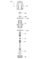
- FIG. 2 is an exploded view showing the structure of a pressure regulating valve.
- FIG. 4 is a schematic diagram showing the pressure state of each seal space.
- FIG. 6 is a cross-sectional view showing a sealing device according to a second embodiment of the present invention.
- FIG. 11 is a cross-sectional view showing a sealing device according to a third embodiment of the present invention.
- the sealing device according to the first embodiment will be described with reference to Figures 1 to 3.
- a sealing device used in the stern tube of a ship will be described as an example.
- the left side of Figure 1 will be the stern side (outboard side) of the sealing device, and the right side of Figure 1 will be the bow side (inboard side) of the sealing device.
- the sealing device 1 is a shaft sealing device for a ship's propulsion engine.
- a bearing (not shown) is disposed inside the stern tube 100 through which the propeller shaft 2, which serves as a rotating shaft having a propeller 3 for propulsion, is inserted, and lubricating oil OL1 is sealed in as a sealed fluid.
- a seal device 1 is disposed on the stern side of the stern tube 100 to prevent lubricating oil OL1 as an internal fluid from leaking out of the ship from between the stern tube 100 and a liner 4 that is fitted and fixed to the propeller shaft 2, and to prevent seawater SW1 as an external fluid from entering the ship.
- the liner 4 constitutes part of the propeller shaft 2.
- a sealing device (not shown) is provided on the bow side of the stern tube 100 to prevent lubricating oil from leaking between the stern tube 100 and the propeller shaft 2 into the machinery room inside the ship.
- the sealing device 1 is mainly composed of a housing 10 as a cylindrical body, a first lip seal 21 to a sixth lip seal 26, and a pressure reducing valve 30 as a pressure adjusting device.
- the housing 10 is formed in a generally cylindrical shape by, in order from the stern side, connecting together the first split housing 10a, the second split housing 10b, the third split housing 10c, the fourth split housing 10d, the fifth split housing 10e, the sixth split housing 10f, and the seventh split housing 10g, which are fitted together in the axial direction, with bolts or the like (not shown).
- the flange portion formed on the seventh split housing 10g on the bow side of the housing 10 is fixed to the stern tube 100 by bolts or the like (not shown).
- the outer diameter portion of the first lip seal 21 is held in a sealed state between the first split housing 10a and the second split housing 10b.
- the outer diameter portion of the second lip seal 22 is held in a sealed state between the second split housing 10b and the third split housing 10c.
- the outer diameter portion of the third lip seal 23 is held in a sealed state between the third split housing 10c and the fourth split housing 10d.
- the outer diameter portion of the fourth lip seal 24 is held in a sealed state between the fourth split housing 10d and the fifth split housing 10e.
- the outer diameter portion of the fifth lip seal 25 is held in a sealed state between the fifth split housing 10e and the sixth split housing 10f.
- the outer diameter portion of the sixth lip seal 26 is held in a sealed state between the sixth split housing 10f and the seventh split housing 10g.
- a seal 5 is attached to the inner circumferential surface of the first split housing 10a to prevent the ingress of foreign matter.
- a first seal space S1 is formed between the seal 5 and the first lip seal 21.
- a second seal space S2 is formed between the first lip seal 21 and the second lip seal 22.
- a third seal space S3 is formed between the second lip seal 22 and the third lip seal 23.
- a fourth seal space S4 is formed between the third lip seal 23 and the fourth lip seal 24.
- a fifth seal space S5 is formed between the fourth lip seal 24 and the fifth lip seal 25.
- a sixth seal space S6 is formed between the fifth lip seal 25 and the sixth lip seal 26.
- An oil chamber S7 is formed inside the stern tube 100 on the inboard side of the sixth seal space S6.
- the first lip seal 21 is positioned so that its lip portion 21a faces outboard, and the pressure on the inboard side of the first lip seal 21, i.e., the pressure in the first seal space S1, acts as part of the tightening pressure on the lip portion 21a.
- the second lip seal 22, fourth lip seal 24, fifth lip seal 25, and sixth lip seal 26 have approximately the same configuration as the first lip seal 21.
- the third lip seal 23 is positioned so that its lip portion 23a faces the inboard side of the ship, and the pressure on the inboard side of the third lip seal 23, i.e., the pressure in the fourth seal space S4, acts as part of the tightening pressure on the lip portion 23a.
- a second seal space S2 is formed in the second split housing 10b.
- the third split housing 10c is formed with a communication hole 13 that connects the third seal space S3 to the external air introduction device 41, and a discharge hole (not shown) that connects the third seal space S3 to the external discharge tank 42.
- the fourth split housing 10d has a communication hole 14 that connects the fourth seal space S4 to the first oil supply device 43.
- the fifth split housing 10e is formed with a communication hole (not shown) that connects the fifth sealing space S5 to the second oil supply device 44, and a communication hole 61 that constitutes part of the flow path 6 that connects the fifth sealing space S5 to the sixth sealing space S6.
- the communication hole 61 is roughly T-shaped, with a radially penetrating portion and a portion that branches off toward the ship's inboard side halfway through.
- a pressure reducing valve 30, which will be described later, is attached to the outer diameter side of the radially penetrating portion of the communication hole 61.
- the sixth split housing 10f also has a communication hole 62 that connects the fifth seal space S5 and the sixth seal space S6 and constitutes part of the flow path 6 together with the communication hole 61.
- the communication hole 62 extends in an inverted L-shape from the branching point of the communication hole 61 and communicates with the sixth seal space S6.
- the flow path 6 of the present invention is composed of a communication hole 61 and a communication hole 62, and connects the fifth sealing space S5 and the sixth sealing space S6.
- the sixth split housing 10f also has a drain hole (not shown) that connects the sixth seal space S6 to the external drain tank 45.
- the discharge tank 42 and the discharge tank 45 are provided separately, but the same discharge tank may be used for both.
- the pressure reducing valve 30 is a poppet valve and is mainly composed of a fixed plug 31, a pressure adjustment rod 32, a push plate 33, a spring 34, a valve body 35, a valve seat member 36, and a cap 37.
- the fixing plug 31 is screwed and fixed via a gasket 30a to the outer diameter side of the radially penetrating portion of the communication hole 61 of the fifth split housing 10e.
- the pressure adjustment rod 32 is screwed and fixed to the fixed plug 31 so that its position can be adjusted.
- a fixed nut 30c is screwed to the part of the pressure adjustment rod 32 that protrudes outward from the fixed plug 31 via a spring washer 30b, preventing the screwed state between the pressure adjustment rod 32 and the fixed plug 31 from loosening due to vibration, etc.
- a cap 37 is fitted and fixed to the outside of the fixing plug 31 via a gasket 30d.
- a valve body 35 is arranged on the inner diameter side of the pressure adjustment rod 32 in the fixed plug 31 so that it can move toward and away from the valve seat member 36 via a push plate 33 and a spring 34.
- a valve seat member 36 is screwed and fixed to the inner diameter side of the radially penetrating portion of the communication hole 61 of the fifth housing split 10e.
- This valve seat member 36 has a valve seat, and the opening degree of the flow path 6 can be adjusted by moving the valve body 35 toward and away from the valve seat.
- seawater SW1 flows into the first seal space S1 through the gap between the seal 5 and the liner 4, and the pressure is approximately the same as that of the outside space S8.
- the air introduced into the second seal space S2 is blown out from between the first lip seal 21 and the liner 4 toward the first seal space.
- the pressure in the second seal space S2 is adjusted to be higher than seawater pressure and lower than the pressure in the fourth seal space S4.
- Air A whose pressure is lower than the pressure in the second sealing space S2 and the pressure in the fourth sealing space S4, is constantly introduced into the third sealing space S3 from the air introduction device 41.
- the air introduction device 41 detects the pressure in the second sealing space S2 and the pressure in the fourth sealing space S4 using a pressure sensor (not shown), and adjusts the pressure of the air A so that it is lower than the detected pressure in the second sealing space S2 and the pressure in the fourth sealing space S4.
- the pressure in the third seal space S3 is lower than the pressure in the second seal space S2, which is the clamping pressure of the lip portion 22a of the second lip seal 22, so the sealing force of the second lip seal 22 can be increased.
- the pressure in the third seal space S3 is lower than the pressure in the fourth seal space S4, which is the clamping pressure of the lip portion 23a of the third lip seal 23, so the sealing force of the third lip seal 23 can be increased.
- the third sealing space S3 is connected to the discharge tank 42, even if seawater SW2 in the second sealing space S2 and/or lubricating oil OL2 in the fourth sealing space S4 flow into the third sealing space S3, it can be collected in the external discharge tank 42.
- An opening and closing valve is formed in the flow path between the third sealing space S3 and the discharge tank 42, so that the communication state can be changed as appropriate.
- the fourth seal space S4 is constantly supplied with lubricating oil OL2 from the first oil supply device 43 at a pressure slightly higher than that of the oil chamber S7.
- the fifth sealing space S5 is constantly supplied with lubricating oil OL3 from the second oil supply device 44, which has a lower pressure than the pressure in the fourth sealing space S4.
- the pressure in the fifth sealing space S5 is adjusted by the amount of throttling of the pressure reducing valve 30, and is lower than the pressure in the fourth sealing space S4.
- the pressure in the fifth seal space S5 is lower than the pressure in the fourth seal space S4, which is the clamping pressure of the lip portion 24a of the fourth lip seal 24, so the sealing force of the fourth lip seal 24 can be increased.
- the pressure in the fifth sealing space S5 pushes up the valve body 35 of the pressure reducing valve 30, and the lubricating oil OL3 in the fifth sealing space S5 flows into the sixth sealing space S6 through the part of the flow path 6 that is restricted by the pressure reducing valve 30.
- the lubricating oil OL4 which has been reduced in pressure due to pressure loss when passing through the pressure reducing valve 30, flows into the sixth sealing space S6, so the pressure in the sixth sealing space S6 becomes lower than the pressure in the fifth sealing space S5.
- the pressure in the sixth seal space S6 is lower than the pressure in the fifth seal space S5, which is the clamping pressure of the lip portion 25a of the fifth lip seal 25, so the sealing force of the fifth lip seal 25 can be increased.
- the lubricating oil OL1 in the oil chamber S7 may enter the sixth sealing space S6, but the lubricating oil OL1 that has entered the sixth sealing space S6 can be discharged to the discharge tank 45.
- an opening and closing valve is provided in the flow path between the sixth sealing space S6 and the discharge tank 45, so that the communication state can be changed as appropriate.
- the lubricating oil OL3 adjusted by the second oil supply device 44 and introduced into the fifth seal space S5 can be reduced in pressure by the pressure reducing valve 30 and introduced into the sixth seal space S6, so that the fifth seal space S5 and the sixth seal space S6 can each be easily adjusted to an appropriate pressure. Furthermore, since there is no need for a separate oil supply device different from the second oil supply device 44, the structure can be made compact.
- the flow path 6 is provided in the housing 10. This eliminates the need to provide piping or a pressure reducing valve 30 outside the housing 10 to connect the fifth sealing space S5 and the sixth sealing space S6, making it possible to further compact the structure.
- the sixth seal space S6 is located on the inboard side of the fifth seal space S5, and the oil chamber S7 is located further inboard of the sixth seal space S6, so that lubricating oil OL1 that attempts to leak from the oil chamber S7 to the outboard side can be collected in the low-pressure sixth seal space S6, and the high-pressure fifth seal space S5 is located outboard of the sixth seal space S6, so that leakage of lubricating oil OL1 to the outboard side can be prevented.
- the sixth seal space S6 contains the same lubricating oil as the oil chamber S7, there is no problem if the oil leaks from the oil chamber S7 into the sixth seal space S6.
- a low-pressure third sealing space S3 into which air A is introduced is disposed between the fourth sealing space S4 and the second sealing space S2, so even if lubricating oil or seawater leaks into the third sealing space S3, it can be recovered, and there is no risk of leakage outside the ship.
- the lubricating oil and seawater recovered in the third sealing space S3 can be discharged into the discharge tank 42, so it is possible to prevent overflow from the third sealing space S3 into the fourth sealing space S4 or the second sealing space S2.
- the fifth seal space S5 and the sixth seal space S6 are adjacent to each other, and the fifth lip seal 25 that separates the fifth seal space S5 and the sixth seal space S6 is designed so that the sealing force is increased by the pressure difference between the fifth seal space S5 and the sixth seal space S6, effectively preventing leakage of lubricating oil.
- lubricating oil is less likely to leak from the gap between the fifth lip seal 25 and the liner 4, it is easy to adjust the pressure in the fifth seal space S5 and the sixth seal space S6.
- the sixth sealing space S6 can be connected to the discharge tank 45 by an on-off valve, allowing the lubricating oil OL4 to be discharged to the outside. This allows the fluid pressure in the sixth sealing space S6 to be adjusted by opening and closing the on-off valve.
- valve body 35 of the pressure reducing valve 30 is biased toward the valve seat member 36 by the spring 34, the opening degree is adjusted according to fluctuations in the differential pressure between the fifth sealing space S5 and the sixth sealing space S6, and the pressure in the fifth sealing space S5 and the sixth sealing space S6 can be appropriately adjusted.
- an example is given of a configuration in which the first seal space S1 to the sixth seal space S6 are provided, but it is sufficient that at least the fifth seal space S5 and the sixth seal space S6 are provided.
- the fifth seal space S5 may be located on the inboard side
- the sixth seal space S6 may be located on the outboard side.
- the fifth sealing space S5 and the sixth sealing space S6 are adjacent to each other, but a different sealing space may be formed between the fifth sealing space S5 and the sixth sealing space S6.
- a flow path 6 that connects the fifth seal space S5 and the sixth seal space S6 is formed in the housing 10, but the fifth seal space S5 and the sixth seal space S6 may also be connected to each other by connecting a pipe provided outside the housing 10 to an opening in the housing.
- an example is given of a configuration in which the same lubricating oil as that in the oil chamber S7 is introduced into the fourth seal space S4, the fifth seal space S5, and the sixth seal space S6, but this is not limited thereto, and a fluid different from that in the oil chamber S7 may be introduced.
- the lip portion of the sixth lip seal 26 is arranged so as to face the high-pressure side of the sixth seal space S6 and the oil chamber S7.
- the pressure reducing valve 30 is also attached to the housing 10 from the outside by screwing it in. This makes it easy to assemble and replace the pressure reducing valve 30.
- the pressure reducing valve 30 allows the pressure adjustment rod 32 to be adjusted from outside the housing 10, making it easy to adjust the biasing force of the spring 34.
- the sealing device 201 of this embodiment 2 is disposed on the bow side of the stern tube 100, and prevents the lubricating oil in the oil chamber S7 from leaking into the machinery room S9 inside the ship from between the stern tube 100 and a liner 204 that is fitted and fixed to the outside of the propeller shaft 2.
- the machinery room S9 is an atmospheric space.
- the sealing device 201 is mainly composed of a housing 210 as a cylindrical body, a first lip seal 221 to a third lip seal 223, and a pressure reducing valve 230 as a pressure adjusting device.
- the housing 210 is formed into a generally cylindrical shape by, in order from the bow side, fitting the first split housing 210a, the second split housing 210b, the third split housing 210c, and the fourth split housing 210d together in the axial direction and connecting them together with bolts (not shown).
- the flange portion formed on the fourth split housing 210d on the stern side is fixed to the stern tube 100 by bolts 7.
- the outer diameter portion of the first lip seal 221 is hermetically held between the first split housing 210a and the second split housing 210b.
- the outer diameter portion of the second lip seal 222 is hermetically held between the second split housing 210b and the third split housing 210c.
- the outer diameter portion of the third lip seal 223 is hermetically held between the third split housing 210c and the fourth split housing 210d.
- the lip portions of the first lip seal 221 to the third lip seal 223 face outboard.
- a seal space S11 is formed between the first lip seal 221 and the second lip seal 222.
- a seal space S12 is formed between the second lip seal 222 and the third lip seal 223.
- the outboard side of the third lip seal 223 is the oil chamber S7.
- the second split housing 210b and the third split housing 210c have a flow path 206 that connects the sealing spaces S11 and S12.
- a pressure reducing valve 230 is attached to the third split housing 210c so as to be able to open and close the flow path 206.
- the pressure reducing valve 230 has substantially the same configuration as the pressure reducing valve 30 in the first embodiment, and therefore a detailed description thereof will be omitted.
- the sealed space S11 is also connected to the discharge tank 245.
- An orifice 8 is provided in the flow path between the sealed space S11 and the discharge tank 245.
- the seal space S12 is also connected to an oil supply device 244.
- This oil supply device 244 constantly introduces lubricating oil at a pressure slightly lower than the pressure in the oil chamber S7 into the seal space S12.
- the lubricating oil in the sealing space S12 is introduced into the sealing space S11 through a flow path 206 in which the opening of the pressure reducing valve 30 is adjusted according to the pressure difference between the sealing spaces S11 and S12. As a result, the pressure in the sealing space S11 is lower than that in the sealing space S12.
- the order of fluid pressure is oil chamber S7 > seal space S12 > seal space S11 > machine chamber S9.
- This improves the sealing ability of the third lip seal 223 due to the pressure difference between the oil chamber S7 and seal space S12, improves the sealing ability of the second lip seal 222 due to the pressure difference between seal space S12 and seal space S11, and improves the sealing ability of the first lip seal 221 due to the pressure difference between seal space S11 and machine chamber S9. This prevents lubricating oil from leaking into the machine chamber S9.
- the sealing device 301 of this embodiment 3 is mainly composed of a housing 310 as a cylindrical body, a first lip seal 321 to a fourth lip seal 324, and pressure reducing valves 330A and 330B as pressure adjusting devices.
- the housing 310 is formed in a generally cylindrical shape by, in order from the stern side, fitting together the first split housing 310a, the second split housing 310b, the third split housing 310c, the fourth split housing 310d, and the fifth split housing 310e in the axial direction and connecting them together with bolts (not shown).
- the flange portion formed on the fifth split housing 310e on the stern side is fixed to the stern tube 100 by bolts 9.
- the outer diameter portion of the first lip seal 321 is hermetically held between the first split housing 310a and the second split housing 310b.
- the outer diameter portion of the second lip seal 322 is hermetically held between the second split housing 310b and the third split housing 310c.
- the outer diameter portion of the third lip seal 323 is hermetically held between the third split housing 310c and the fourth split housing 310d.
- the outer diameter portion of the fourth lip seal 324 is hermetically held between the fourth split housing 310d and the fifth split housing 310e.
- the lip portions of the first lip seal 321 to the third lip seal 323 face outboard.
- the lip portion of the fourth lip seal 324 faces inboard.
- a seal space S31 is formed between the first lip seal 321 and the second lip seal 322.
- a seal space S32 is formed between the second lip seal 322 and the third lip seal 323.
- a seal space S33 is formed between the third lip seal 323 and the fourth lip seal 324.
- the second split housing 310b and the third split housing 310c are provided with a flow path 361 that connects the sealing spaces S31 and S32.
- the third split housing 310c and the fourth split housing 310d are provided with a flow path 362 that connects the sealing spaces S32 and S33.
- the pressure reducing valve 330A is attached to the second split housing 310b so as to be able to open and close the flow path 361.
- the pressure reducing valve 330B is attached to the third split housing 310c so as to be able to open and close the flow path 362. Note that the pressure reducing valves 330A and 330B have substantially the same configuration as the pressure reducing valve 30 in the first embodiment, and therefore a detailed description thereof will be omitted.
- Water W is sealed in the internal space S37 of the stern tube 100, and the water W enhances the lubrication of the bearings.
- a storage tank 341 for storing water is disposed outside the internal space S37.
- This storage tank 341 is connected to a pump 342.
- the pump 342 is capable of pressurizing and introducing the water in the storage tank 341 into the internal space S37 and the sealed space S31.
- the pressure of the water W introduced into the sealed space S31 is lower than the pressure of the seawater SW in the outboard space S38.
- the water W introduced into the sealed space S31 is depressurized by the pressure reducing valve 330A and introduced into the sealed space S32.
- the water W introduced into the sealed space S32 is depressurized by the pressure reducing valve 330B and introduced into the sealed space S33. That is, the pressure in each space is outboard space S38 > sealed space S31 > sealed space S32 > sealed space S33. Also, the pressure in the sealed space S33 is lower than the internal space S37.
- the pressure difference between the outboard space S38 and the seal space S31 improves the sealing ability of the first lip seal 321
- the pressure difference between the seal space S31 and the seal space S32 improves the sealing ability of the second lip seal 322
- the pressure difference between the seal space S32 and the seal space S33 improves the sealing ability of the third lip seal 323
- the pressure difference between the seal space S33 and the internal space S37 improves the sealing ability of the fourth lip seal 324. This makes it possible to prevent seawater SW from flowing into the internal space S37.
- the water W introduced into the sealed space S33 is discharged into the storage tank 341.
- the water W in the internal space S37 is also discharged into the storage tank 341.
- the pressure of the water W introduced into the sealed space S31 is lower than the pressure of the seawater SW in the outboard space S38, but the sealed space S31 and the outboard space S8 may be at the same pressure, or the pressure of the water W introduced into the sealed space S31 may be higher than the pressure of the seawater SW in the outboard space S38. This is because the water W is fresh water, and there is no problem if it is discharged into the outboard space S38.
- each seal space is reduced toward the inside of the ship, but the pressure in each seal space may be reduced toward the outside of the ship.
- the external fluid is seawater, but this can be freely changed to fresh water, oil, air, gas, etc.
- the internal fluid is not limited to lubricating oil or water, but can be air, gas, etc.
- the lip seal is in sliding contact with the outer peripheral surface of the liner fitted onto the propeller shaft, but this is not limiting, and the lip seal may be in direct sliding contact with the outer peripheral surface of the propeller shaft 2 without using a liner.
- a pressure reducing valve was used as an example of the pressure adjusting device, but a throttle mechanism such as an orifice may also be used.
- the pressure adjusting device is not limited to one that reduces pressure from one sealed space and supplies it to the other sealed space, but may also be one that increases pressure and supplies it.
- the pressure reducing valve is not limited to a poppet valve, but may be a spool valve, etc.
- each seal ring is not limited to being composed of a lip seal, but may be, for example, an end face seal.
- Sealing device 2 Propeller shaft (rotating shaft) 6 Flow path 10 Housing (cylindrical body) 25 5th lip seal (seal ring) 30 Pressure reducing valve (pressure adjusting device) 34 Spring 35 Valve body 36 Valve seat member 41 Air introduction device 42 Discharge tank 43 First oil supply device 44 Second oil supply device 45 Discharge tank 100 Stern tube S5 Fifth seal space (one of the seal spaces) S6: Sixth seal space (the other seal space) S7 Oil chamber S8 Outside space
Landscapes
- Engineering & Computer Science (AREA)
- General Engineering & Computer Science (AREA)
- Mechanical Engineering (AREA)
- Sealing With Elastic Sealing Lips (AREA)
- Sealing Devices (AREA)
Priority Applications (3)
| Application Number | Priority Date | Filing Date | Title |
|---|---|---|---|
| CN202480042962.5A CN121399404A (zh) | 2023-07-19 | 2024-06-26 | 密封装置 |
| JP2025533937A JP7804837B2 (ja) | 2023-07-19 | 2024-06-26 | シール装置 |
| KR1020257043742A KR20260020139A (ko) | 2023-07-19 | 2024-06-26 | 시일 장치 |
Applications Claiming Priority (2)
| Application Number | Priority Date | Filing Date | Title |
|---|---|---|---|
| JP2023-117385 | 2023-07-19 | ||
| JP2023117385 | 2023-07-19 |
Publications (1)
| Publication Number | Publication Date |
|---|---|
| WO2025018114A1 true WO2025018114A1 (ja) | 2025-01-23 |
Family
ID=94281415
Family Applications (1)
| Application Number | Title | Priority Date | Filing Date |
|---|---|---|---|
| PCT/JP2024/023152 Pending WO2025018114A1 (ja) | 2023-07-19 | 2024-06-26 | シール装置 |
Country Status (4)
| Country | Link |
|---|---|
| JP (1) | JP7804837B2 (https=) |
| KR (1) | KR20260020139A (https=) |
| CN (1) | CN121399404A (https=) |
| WO (1) | WO2025018114A1 (https=) |
Citations (3)
| Publication number | Priority date | Publication date | Assignee | Title |
|---|---|---|---|---|
| JPH0182999U (https=) * | 1987-11-25 | 1989-06-02 | ||
| JPH04113081A (ja) * | 1990-08-30 | 1992-04-14 | Hitachi Ltd | ポンプ封水装置 |
| WO2018216155A1 (ja) | 2017-05-24 | 2018-11-29 | バルチラジャパン株式会社 | 船尾管用油循環システム及び船舶 |
Family Cites Families (6)
| Publication number | Priority date | Publication date | Assignee | Title |
|---|---|---|---|---|
| DE2143736A1 (de) * | 1971-09-01 | 1973-03-08 | Erno Raumfahrttechnik Gmbh | Anordnung zum abdichten von wellendurchfuehrungen |
| DE2926660C2 (de) * | 1979-07-02 | 1984-12-06 | Howaldtswerke-Deutsche Werft Ag Hamburg Und Kiel, 2300 Kiel | Ölgeschmierte Stevenrohrlager- und Dichtungsanordnung |
| CN101788057B (zh) * | 2009-01-22 | 2011-11-09 | 江苏华阳重工股份有限公司 | 高性能自调压船舶油润滑密封装置 |
| CN201359088Y (zh) * | 2009-01-22 | 2009-12-09 | 江苏华阳重工科技股份有限公司 | 油压自调整船舶油润滑密封装置 |
| CN102388245B (zh) * | 2010-06-10 | 2014-08-27 | 瓦锡兰日本株式会社 | 密封环及船尾管密封装置 |
| CN208431376U (zh) * | 2018-06-15 | 2019-01-25 | 上海威纳工程技术有限公司 | 半潜船减摇鳍密封装置 |
-
2024
- 2024-06-26 JP JP2025533937A patent/JP7804837B2/ja active Active
- 2024-06-26 CN CN202480042962.5A patent/CN121399404A/zh active Pending
- 2024-06-26 KR KR1020257043742A patent/KR20260020139A/ko active Pending
- 2024-06-26 WO PCT/JP2024/023152 patent/WO2025018114A1/ja active Pending
Patent Citations (3)
| Publication number | Priority date | Publication date | Assignee | Title |
|---|---|---|---|---|
| JPH0182999U (https=) * | 1987-11-25 | 1989-06-02 | ||
| JPH04113081A (ja) * | 1990-08-30 | 1992-04-14 | Hitachi Ltd | ポンプ封水装置 |
| WO2018216155A1 (ja) | 2017-05-24 | 2018-11-29 | バルチラジャパン株式会社 | 船尾管用油循環システム及び船舶 |
Also Published As
| Publication number | Publication date |
|---|---|
| CN121399404A (zh) | 2026-01-23 |
| JP7804837B2 (ja) | 2026-01-22 |
| JPWO2025018114A1 (https=) | 2025-01-23 |
| KR20260020139A (ko) | 2026-02-10 |
Similar Documents
| Publication | Publication Date | Title |
|---|---|---|
| EP3209919B1 (en) | Gas pressurized packing system for control valves | |
| AU2010200828B2 (en) | Pressure balanced shaft seal assembly | |
| US9285039B2 (en) | Sleeve seal assembly and rotary valve having sleeve seal assembly | |
| US8490945B2 (en) | Valve sealing arrangements and methods | |
| US11261799B2 (en) | Combined ball valve for compressor bleed air and methods | |
| US20080196773A1 (en) | Ventline control valve assembly | |
| US20090317031A1 (en) | Roller bearing unit and gas control valve arrangement comprising a roller bearing unit | |
| US20190162320A1 (en) | Flow control valve | |
| CN108291482B (zh) | 涡轮增压器、发动机系统 | |
| US6830069B2 (en) | Isolation valve assembly | |
| JP2024107363A (ja) | シール装置 | |
| US8029672B2 (en) | Filter head | |
| JP7804837B2 (ja) | シール装置 | |
| JP2006234101A (ja) | 船舶用推進軸の軸封装置 | |
| US5195786A (en) | Internally-located dual flow rotating union | |
| FI107638B (fi) | Säätöventtiili | |
| CN102197253A (zh) | 包括多密封件压强调节系统的高压流体旋转装置 | |
| EP3279527B1 (en) | Mechanical seal system for a drive shaft extending through an opening in a bulkhead | |
| JP2023047451A (ja) | メカニカルシール、及びメカニカルシールの流体圧調整方法 | |
| JP7797990B2 (ja) | 複数の冷却水減圧装置間の冷却水共用機構 | |
| PL92648B1 (https=) | ||
| KR20170110303A (ko) | 밸브 블록 |
Legal Events
| Date | Code | Title | Description |
|---|---|---|---|
| 121 | Ep: the epo has been informed by wipo that ep was designated in this application |
Ref document number: 24842909 Country of ref document: EP Kind code of ref document: A1 |
|
| ENP | Entry into the national phase |
Ref document number: 2025533937 Country of ref document: JP Kind code of ref document: A |
|
| WWE | Wipo information: entry into national phase |
Ref document number: 2025533937 Country of ref document: JP |
|
| ENP | Entry into the national phase |
Ref document number: 1020257043742 Country of ref document: KR Free format text: ST27 STATUS EVENT CODE: A-0-1-A10-A15-NAP-PA0105 (AS PROVIDED BY THE NATIONAL OFFICE) |
|
| WWE | Wipo information: entry into national phase |
Ref document number: 2024842909 Country of ref document: EP |
|
| NENP | Non-entry into the national phase |
Ref country code: DE |