WO2025018097A1 - 表示装置及び表示システム - Google Patents
表示装置及び表示システム Download PDFInfo
- Publication number
- WO2025018097A1 WO2025018097A1 PCT/JP2024/022559 JP2024022559W WO2025018097A1 WO 2025018097 A1 WO2025018097 A1 WO 2025018097A1 JP 2024022559 W JP2024022559 W JP 2024022559W WO 2025018097 A1 WO2025018097 A1 WO 2025018097A1
- Authority
- WO
- WIPO (PCT)
- Prior art keywords
- image
- notification
- driver
- control unit
- display screen
- Prior art date
- Legal status (The legal status is an assumption and is not a legal conclusion. Google has not performed a legal analysis and makes no representation as to the accuracy of the status listed.)
- Pending
Links
Images



Classifications
-
- B—PERFORMING OPERATIONS; TRANSPORTING
- B60—VEHICLES IN GENERAL
- B60K—ARRANGEMENT OR MOUNTING OF PROPULSION UNITS OR OF TRANSMISSIONS IN VEHICLES; ARRANGEMENT OR MOUNTING OF PLURAL DIVERSE PRIME-MOVERS IN VEHICLES; AUXILIARY DRIVES FOR VEHICLES; INSTRUMENTATION OR DASHBOARDS FOR VEHICLES; ARRANGEMENTS IN CONNECTION WITH COOLING, AIR INTAKE, GAS EXHAUST OR FUEL SUPPLY OF PROPULSION UNITS IN VEHICLES
- B60K35/00—Instruments specially adapted for vehicles; Arrangement of instruments in or on vehicles
- B60K35/20—Output arrangements, i.e. from vehicle to user, associated with vehicle functions or specially adapted therefor
- B60K35/21—Output arrangements, i.e. from vehicle to user, associated with vehicle functions or specially adapted therefor using visual output, e.g. blinking lights or matrix displays
- B60K35/23—Head-up displays [HUD]
-
- G—PHYSICS
- G08—SIGNALLING
- G08G—TRAFFIC CONTROL SYSTEMS
- G08G1/00—Traffic control systems for road vehicles
- G08G1/16—Anti-collision systems
Definitions
- the present invention relates to a display device and a display system.
- Patent document 1 describes how, when the vehicle speed exceeds the speed limit, a graphic of the speed limit is highlighted (for example, alternately displayed in inverted and non-inverted) on the head-up display.
- the purpose of notifications about exceeding the speed limit, etc. is to alert the driver. However, if notifications about exceeding the speed limit, etc. are displayed near the driver's point of view, there is a risk that the driver will find them annoying.
- the present invention aims to solve the conflicting problems of alerting the driver while minimizing discomfort to the driver.
- One embodiment of the present invention for achieving the above object is a display device that includes an image generating unit that generates an image, an optical system that projects the image as image light onto a transmissive reflecting unit to display a virtual image, and a control unit that displays a notification image for notification in a strip-like region at the bottom edge of the virtual image.
- the present invention makes it possible to alert the driver while minimizing discomfort to the driver.
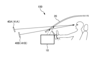
- FIG. 1 is an explanatory diagram of a display device 10.
- FIG. 2 is a block diagram of the display device 10.
- FIG. 3 is an explanatory diagram of a display screen 41 on which a virtual image 40 is projected.
- Fig. 4A is an explanatory diagram of an example of the display screen 41.
- Fig. 4B is an explanatory diagram of the display screen 41 including a notification image 44.
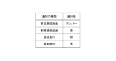
- FIG. 5 is a table showing the relationship between the type of notification and the color (notification color) of the notification image 44.
- FIG. 6 is an explanatory diagram of a display device 10 according to a modified example.
- Fig. 1 is an explanatory diagram of a display device 10.
- Fig. 2 is a block diagram of the display device 10.
- the display device 10 is a device that displays an image to the driver.
- the display device 10 is a so-called head-up display (HUD) device.
- the display device 10 is a device that displays an image (virtual image 40) superimposed on an actual background within the driver's field of vision.
- the figure shows the display device 10 projecting image light onto the windshield (front glass) and projecting the virtual image 40 onto the windshield.
- the transmission reflection unit 20 that projects the virtual image 40 is not limited to the windshield, and may be a combiner installed inside the vehicle.
- the display device 10 includes an image generation unit 11, an optical system 12, and a control unit 13.
- the display system 100 is a system in which the transmission reflection unit 20 is added to the display device 10 (which includes the image generation unit 11, the optical system 12, and the control unit 13).
- the image generating unit 11 is a device that generates an image.
- the image generating unit 11 is, for example, configured with a liquid crystal display device, an organic EL display device, a micro LED display device, or a projector device using a laser light source.
- the image generating unit 11 generates an image based on a signal (image signal) from the control unit 13.
- the image generated by the image generating unit 11 is irradiated to the optical system 12 as image light.
- the optical system 12 projects the image generated by the image generation unit 11 onto the transmission reflection unit 20 as image light.
- the optical system 12 is composed of one or more optical elements.
- the optical elements that make up the optical system 12 are, for example, lenses, mirrors, prisms, etc.
- the optical system 12 is configured so that a virtual image 40 is displayed to the driver.
- the optical system 12, together with the transmission reflection unit 20, constitutes an imaging optical system that allows the driver to visually recognize the virtual image 40. For this reason, the optical system 12 is designed taking into account the optical characteristics of the transmission reflection unit 20.
- the transmissive reflector 20 reflects the image light from the optical system 12 while transmitting light from outside the vehicle.
- the transmissive reflector 20 functions as a so-called half mirror.
- the transmissive reflector 20 is a windshield (front glass).
- the transmissive reflector 20 may also be a combiner installed inside the vehicle.
- the transmissive reflector 20 forms a virtual image 40 by reflecting the image light from the optical system 12. The driver sees a superimposed image of the background seen due to the transmission of light by the transmissive reflector 20 and the virtual image 40 (spatial image) seen due to the reflection of the image light by the transmissive reflector 20.
- the control unit 13 is responsible for controlling the display device 10.
- the control unit 13 outputs an image signal to the image generation unit 11, causing the image generation unit 11 to generate an image.
- the image generation unit 11 generates an image according to the image signal from the control unit 13. In this way, the control unit 13 controls the image generation unit 11 via the image signal.
- the control unit 13 obtains a detection signal from the detection unit 30.
- the detection unit 30 detects a physical quantity indicating the external situation and outputs the detection result as a detection signal to the control unit 13.
- the detection unit 30 includes, for example, a vehicle speed detection unit (e.g., a vehicle speed sensor) that detects the vehicle speed, a distance measuring device such as LiDAR (Light Detection and Ranging, Laser Imaging Detection and Ranging), and a position detection unit (e.g., a GPS (Global Positioning System) module) that detects the current position.
- a vehicle speed detection unit e.g., a vehicle speed sensor
- LiDAR Light Detection and Ranging, Laser Imaging Detection and Ranging
- a position detection unit e.g., a GPS (Global Positioning System) module
- the detection unit 30 includes not only a conversion element such as a sensor that detects a physical quantity and converts it into a detection signal, but also a device (e.g., an EUC, etc.) that converts the output signal of the sensor and outputs another signal (detection signal).
- the control unit 13 outputs an image signal according to the detected situation based on the detection signal from the detection unit 30.
- the control unit 13 also determines whether or not a notification is required based on the detection signal from the detection unit 30, and if a notification is required, generates an image signal for displaying a notification image 44 (described later).
- the control unit 13 includes an image processing unit 14 and a determination unit 15.
- the image processing unit 14 generates an image signal to be output to the image generation unit 11.
- the determination unit 15 determines the external situation based on a detection signal from the detection unit 30.
- the determination unit 15 also determines whether or not a notification is required for events such as the departure of a vehicle ahead or exceeding the speed limit based on the detection signal from the detection unit 30.
- the image processing unit 14 outputs an image signal according to the determination result of the determination unit 15. The processing of the image processing unit 14 and the determination unit 15 will be described later.
- the control unit 13 is composed of a computer equipped with an arithmetic processing unit such as a CPU or MPU, and a storage device such as a RAM or ROM (main storage device or auxiliary storage device). Each process performed by the control unit 13 (each process performed by the image processing unit 14 and the determination unit 15) is realized by the arithmetic processing unit executing a program stored in the storage device.
- an arithmetic processing unit such as a CPU or MPU
- a storage device such as a RAM or ROM (main storage device or auxiliary storage device).
- FIG. 3 is an explanatory diagram of a display screen 41 on which a virtual image 40 is projected.
- the display screen 41 is a screen (image) that the display device 10 displays as the virtual image 40.
- the display screen 41 is a screen that is projected in the area of the virtual image 40, and is visually recognized by the driver as being located outside the transmissive reflection unit 20 (outside the vehicle).
- the dotted area in FIG. 3 indicates the area in which the display screen 41 is displayed. In other words, the dotted area in FIG. 3 indicates the area of the virtual image 40 shown in FIG. 1, and indicates the area that the display device 10 can display.
- the display device 10 displays the display screen 41 that shows various information within the dotted area in FIG. 3.
- control unit 13 image processing unit 14
- the display screen 41 that is projected as the virtual image 40 will be mainly described, and the image generated by the image generation unit 11 will not be described.
- FIG. 4A is an explanatory diagram of an example of the display screen 41.
- FIG. 4A shows the display screen 41 when no notification is being sent.
- FIG. 4A shows an example of the display screen 41 and information image 42 (42A-42F), and the display screen 41 and information image 42 are not limited to those shown in FIG. 4A.
- an information image other than the information image 42 (42A-42F) shown in FIG. 4A may be displayed on the display screen 41.
- any of the information images 42 (42A-42F) shown in FIG. 4A may not be displayed on the display screen 41.
- all of the information images 42 (42A-42F) shown in FIG. 4A may not be displayed on the display screen 41 (for example, only the notification image 44 described later may be displayed on the display screen 41).
- the display screen 41 shown in FIG. 4A includes information images 42 such as a vehicle speed image 42A, a shift position image 42B, a road sign image 42C, an indicator bar image 42D, a driving assistance image 42E, and a navigation image 42F.
- information images 42 such as a vehicle speed image 42A, a shift position image 42B, a road sign image 42C, an indicator bar image 42D, a driving assistance image 42E, and a navigation image 42F.
- the vehicle speed image 42A is an image showing vehicle speed information.
- the control unit 13 acquires the vehicle speed information from the detection unit 30, and causes the display screen 41 to display the vehicle speed image 42A.
- the shift position image 42B is an image showing a shift position (for example, P, R, N, D, etc.).
- the control unit 13 acquires the shift position information from the ECU functioning as the detection unit 30, and causes the display screen 41 to display the shift position image 42B.
- the road sign image 42C is an image showing a road sign.
- the detection unit 30 includes a camera that captures an image of the front and an image analysis unit, and the image analysis unit analyzes the captured data of the camera to detect road signs and outputs a detection signal showing information about the road signs to the control unit 13.
- the control unit 13 obtains the information about the road signs from the detection unit 30 and displays the display screen 41 including the road sign image 42C.
- the indicator bar image 42D is an image that displays the measurement result of the indicator as a bar.
- the control unit 13 acquires information indicating the measurement result from the detection unit 30 (e.g., an ECU or an indicator) and causes the display screen 41 to display the indicator bar image 42D.
- the driving assistance image 42E is an image showing the status of the driving assistance system.
- the driving assistance system includes a lane keeping function and a following driving function
- the driving assistance image 42E includes an image of a lane showing that the lane keeping function is operating, and an image showing a set speed and a following distance set in the following driving function.
- the control unit 13 acquires information about the driving assistance system from the detection unit 30 (e.g., ECU) and displays the display screen 41 including the driving assistance image 42E.
- the navigation image 42F is an image showing navigation information.
- the control unit 13 acquires the navigation information from a car navigation device functioning as the detection unit 30, and causes the display screen 41 to display the navigation image 42F.
- FIG. 4B is an explanatory diagram of the display screen 41 including a notification image 44.
- FIG. 4B shows the display screen 41 when a notification is in progress.
- the display screen 41 when a notification is in progress is a screen in which the notification image 44 has been added to the display screen 41 when no notification is in progress (see FIG. 4A).
- the notification image 44 is an image for notifying the driver.
- the notification image 44 is an image (information image) for displaying information (notification information) for drawing the driver's attention.
- the notification image 44 is an image that is additionally displayed on the non-notification display screen 41 (see FIG. 4A) when it is necessary to draw the driver's attention.
- the notification image 44 is displayed in a strip-like region at the bottom of the display screen 41 (virtual image 40).
- the control unit 13 image processing unit 14 causes the image generation unit 11 to display an image such that the notification image 44 is displayed in the strip-like region at the bottom of the virtual image 40.
- lower edge refers to the area (region) near the edge (lower edge) that constitutes the lower edge. Additionally, “near” the lower edge means closer to the lower edge than the center in the vertical direction.
- the "lower edge” of the display screen 41 (virtual image 40) refers to the area (region) that occupies the lower 1/4 of the display screen 41 (virtual image 40).
- the notification image 44 is displayed on the lower edge of the display screen 41 (virtual image 40), and therefore occupies the lower 1/4 of the region of the display screen 41 (virtual image 40).
- the lower edge of the notification image 44 shown in FIG. 4B is in contact with the lower side of the display screen 41 (virtual image 40). However, blank pixels may exist between the lower edge of the notification image 44 and the lower side of the display screen 41 (virtual image 40).
- the upper edge of the notification image 44 is located closer to the lower side than the center in the vertical direction of the display screen 41 (virtual image 40).
- the display screen 41 shown in FIG. 4B at least the area between the other information images 42 (for example, the indicator bar image 42D and the driving assistance image 42E located at the bottom) and the lower side of the display screen 41 (virtual image 40) corresponds to the lower side.
- at least a part of the notification image 44 is displayed in the area between the other information images 42 (for example, the indicator bar image 42D and the driving assistance image 42E located at the bottom) and the lower side of the display screen 41 (virtual image 40).
- a "strip-shaped region” refers to a region having an elongated shape (strip-like). Since the notification image 44 is displayed in a strip-shaped region at the bottom edge of the display screen 41 (virtual image 40), the notification image 44 is an elongated image extending in the left-right direction. The left and right edges of the notification image 44 shown in FIG. 4B are in contact with the left and right edges of the display screen 41 (virtual image 40), respectively. However, blank pixels may exist between the left edge of the notification image 44 and the left edge of the display screen 41 (virtual image 40), and blank pixels may exist between the right edge of the notification image 44 and the right edge of the display screen 41 (virtual image 40).
- the notification image 44 is an elongated image along the left-right direction, so that the driver can easily notice it when it appears on the display screen 41.
- the notification image 44 is arranged on the lower side of the display screen 41 (virtual image 40)
- the angle between the line connecting the driver's eyes and the notification image 44 and the driver's line of sight can be made large, so that the discomfort caused to the driver when it appears on the display screen 41 can be suppressed.
- the control unit 13 displays the notification image 44 in a strip-shaped area on the lower side of the display screen 41 (virtual image 40), so that it is possible to solve both the conflicting issues of calling the driver's attention and suppressing the discomfort caused to the driver.
- the width (vertical dimension) of the notification image 44 is set to be relatively narrow. Unlike the vehicle speed image 42A and the road sign image 42C, the notification image 44 does not represent letters (including numbers) or marks, but represents a specific color. Therefore, the notification image 44 can be displayed in a narrower area than the other information images 42, and can perform the notification function even when displayed in a narrow area. For this reason, for example, the width of the notification image 44 can be set narrower than the vertical dimension of the vehicle speed image 42A and the road sign image 42C. By setting the width (vertical dimension) of the notification image 44 narrow, it is possible to prevent the driver from feeling uncomfortable when the notification image 44 appears on the display screen 41.
- the notification image 44 shown in FIG. 4A is composed of a predetermined color (single color), and the displayed area of the notification image 44 is composed of the same color.
- the notification image 44 may also be composed of a gradation image in which the density (brightness) of a single color (same hue) is gradually changed in the left-right direction.
- the control unit 13 displays the notification image 44 by blinking it.
- the blinking notification image 44 strongly calls the driver's attention. Since the notification image 44 represents a predetermined color, there is an advantage that the blinking notification image 44 is less likely to annoy the driver than blinking an information image 42 such as letters or marks.
- control unit 13 may display the notification image 44 continuously (may keep the notification image 44 lit).
- the control unit 13 may animate the notification image 44 so that the shading moves in the left-right direction. This gives movement to the notification image 44, making it easier for the driver to notice the notification.
- the control unit 13 may display the notification image 44 for only a predetermined time (e.g., 10 seconds) and remove the notification image 44 from the display screen 41 after the predetermined time has elapsed.
- the control unit 13 may display the notification image 44 by flashing it a predetermined number of times (e.g., 10 times) and remove the notification image 44 from the display screen 41 after the predetermined number of flashes. This can reduce discomfort to the driver.
- the control unit 13 (image processing unit 14) displays the notification image 44 in different colors depending on the type of notification.
- Figure 5 is a table showing the relationship between the type of notification and the color (notification color) of the notification image 44.
- the control unit 13 When notifying the driver that a vehicle in front has started moving, the control unit 13 displays an amber notification image 44.
- the control unit 13 determineation unit 15 acquires vehicle speed information and distance information to the vehicle in front from the detection unit 30 (e.g., vehicle speed detection unit or LiDAR), and determines that a notification of the vehicle in front is necessary if the driver's own vehicle continues to be stopped even after a predetermined time (e.g., 3 seconds) has elapsed since the vehicle in front started moving after the vehicle in front had stopped together with the own vehicle.
- a predetermined time e.g. 3 seconds
- the control unit 13 When notifying the driver that the speed limit is exceeded, the control unit 13 displays a red notification image 44.
- the control unit 13 determineation unit 15 acquires vehicle speed information and road sign information from the detection unit 30, and determines that a notification of exceeding the speed limit is necessary if the vehicle speed exceeds the speed limit by 10% or more. If a notification of exceeding the speed limit is necessary, the control unit 13 (image processing unit 14) displays a red notification image 44 in a strip-shaped area at the bottom of the virtual image 40. Note that the control unit 13 may increase the blinking speed of the notification image 44 the greater the vehicle speed exceeds the speed limit.
- the control unit 13 may increase the brightness of the notification image 44 the greater the vehicle speed exceeds the speed limit.
- the control unit 13 displays a green notification image 44 when the follow-up driving function of the driving assistance system is activated.
- the control unit 13 determineation unit 15 acquires information about the driving assistance system from the detection unit 30 (e.g., ECU) and determines whether the follow-up driving function is activated.
- the control unit 13 image processing unit 14 displays a green notification image 44 in a strip-shaped area at the bottom edge of the virtual image 40. Note that, in the case of a notification with a high level of urgency, a red or amber notification image 44 is displayed, whereas in the case of a notification with a low level of urgency, a green notification image 44 is displayed.
- the low-level urgency notification image 44 may blink at a slower rate than the high-level urgency notification image 44. This can reduce discomfort to the driver.
- the control unit 13 When notifying the driver of drowsiness detection, the control unit 13 displays a blue notification image 44.
- the detection unit 30 includes a camera that photographs the driver and an image analysis unit, and the image analysis unit analyzes the driver's eye movements based on the camera's photographic data to detect the driver's drowsiness and outputs a detection signal to the control unit 13.
- the control unit 13 determineation unit 15) obtains information about drowsiness from the detection unit 30 and determines whether or not a notification of drowsiness detection is necessary. If a notification of drowsiness detection is necessary, the control unit 13 (image processing unit 14) displays a blue notification image 44 in a strip-shaped region at the bottom of the virtual image 40.
- blue light has an awakening effect, so by having the control unit 13 display the blue notification image 44 when drowsiness is detected, not only can the control unit 13 notify the driver that drowsiness has been detected, but the control unit 13 can also suppress the driver's drowsiness.
- the control unit 13 displays notification images 44 of different colors according to the type of notification in a strip-shaped area at the bottom of the display screen 41 (virtual image 40). Since the color of the notification image 44 differs depending on the type of notification, the driver can distinguish the notification content by the color of the notification image 44. In addition, since the notification image 44 is displayed in the same place, it is easier for the driver to notice the notification. Note that the types of notifications are not limited to those shown in FIG. 5, and other types of notifications may be provided. Furthermore, the color of the notification image 44 is not limited to that shown in FIG. 5, and other colors may be used.
- a warning sound may be generated from a speaker (not shown).
- the warning sound may cause strong discomfort to the driver.
- the control unit 13 image processing unit 14
- the control unit 13 displays a notification screen on the display screen 41 (virtual image 40) before the warning sound is generated. For example, if a warning sound is set to be generated 5 seconds after the vehicle ahead starts, the control unit 13 displays an amber notification image 44 3 seconds after the vehicle ahead starts. This allows the driver to be alerted before the warning sound is generated, and if the driver responds immediately, there is no need to generate a warning sound, which can prevent the warning sound from causing discomfort to the driver.
- the ambient light (not shown) may be flashed when the driver is alerted to the departure of a vehicle ahead, exceeding the speed limit, etc.
- the ambient light is a linear environmental light installed inside the vehicle.
- the control unit 13 obtains a synchronization signal for the flashing of the ambient light from the ECU, and flashes the notification image 44 in sync with the flashing of the ambient light.
- the control unit 13 image processing unit 14 to flash the notification image 44 in the same color family as the ambient light.
- the ambient light When an ambient light is installed above the glove box of the passenger seat, the ambient light is often arranged in a line extending in the left-right direction. If the notification image 44, which is a long, thin strip extending in the left-right direction, flashes in sync with the flashing of the ambient light in a line extending in the left-right direction, the driver will be more likely to notice the flashing of the light. For this reason, when the ambient light is arranged in a line extending in the left-right direction, it is particularly effective to flash the notification image 44 in sync with the flashing of the ambient light.
- the notification image 44 it is desirable for the notification image 44 to overlap with a portion of another information image 42.
- the notification image 44 overlaps with a portion of the text image included in the indicator bar image 42D and the image showing the set speed in the driving assistance image 42E.
- the notification image 44 does not have to overlap with the other information images 42.
- the notification image 44 does not get in the way when the driver checks the other information images 42, and this has the effect of reducing the annoyance felt by the driver.
- the driver's gaze point when driving at high speed on a highway is located higher than the driver's gaze point when driving at low speed in a city area. In this way, when the vehicle speed increases, the driver's gaze point moves upward.
- the notification image 44 of this embodiment is displayed at the lower side of the display screen 41 (virtual image 40)
- the control unit 13 may change the position of the upper edge of the notification image 44 according to the vehicle speed. For example, when the vehicle speed increases, the control unit 13 moves the upper edge of the notification image 44 upward by increasing the width (vertical dimension) of the notification image 44.
- the control unit 13 moves the upper edge of the notification image 44 downward by decreasing the width (vertical dimension) of the notification image 44. This reduces the annoyance felt by the driver. Note that instead of changing the width of the notification image 44, the position of the upper edge of the notification image 44 may be changed by changing the display position of the notification image 44 in the vertical direction.
- the virtual image 40 is inclined with respect to the vertical direction so that the closer it is to the bottom side, the closer it is to the driver (the optical system 12 is configured so that the virtual image 40 is inclined in this way).
- the distance (distance in the front-to-rear direction) between the driver's gaze point and the bottom side of the virtual image 40 is longer than that of the top side. For this reason, the notification image 44 is displayed closer to the driver on the display screen 41.
- the driver's focus (point of gaze) is farther away than the virtual image 40, by displaying the notification image 44 on the bottom side of the inclined virtual image 40 in this way, the distance (distance in the front-to-rear direction) between the driver's focus and the notification image 44 can be increased, and the annoyance felt by the driver when the notification image 44 is displayed can be reduced.
- the notification image 44 does not represent letters or marks, but represents a predetermined color, so the driver can distinguish the color of the notification image 44 without focusing on the notification image 44. For this reason, it is permitted to increase the distance between the driver's focus (point of gaze) and the notification image 44 on the virtual image 40.
- the arrangement of the virtual images 40 is not limited to that shown in FIG. 1.
- the virtual images 40 may be arranged parallel to the vertical direction.
- FIG. 6 is an explanatory diagram of a display device 10 according to a modified example.
- the display device 10 of the modified example forms two virtual images 40 (a first virtual image 40A and a second virtual image 40B).
- the image generating unit 11 (not shown in FIG. 6) has a first image generating unit that generates a first image and a second image generating unit that generates a second image
- the optical system 12 (not shown in FIG. 6) has a first optical system that displays the first virtual image 40A using the first image and a second optical system that displays the second virtual image 40B using the second image.
- the first image generating unit and the second image generating unit may be configured as separate devices (e.g., two liquid crystal display devices), or may be configured as a single device by using a portion of a single image as the first image and another portion as the second image.
- two virtual images 40 are arranged at different positions in the vertical direction.
- two display screens 41 are displayed at different positions in the vertical direction.
- the upper virtual image 40 is the first virtual image 40A
- the lower virtual image 40 is the second virtual image 40B.
- the control unit 13 image processing unit 14
- the angle between the line connecting the driver's eyes and the notification image 44 and the driver's line of sight can be made larger than when the notification image 44 is displayed on the first virtual image 40A on the upper side, so that the discomfort felt by the driver when the notification image 44 appears on the display screen 41 can be suppressed.
- the second virtual image 40B is disposed closer to the driver than the first virtual image 40A.
- the control unit 13 image processing unit 14 displays the notification image 44 in a strip-shaped area at the bottom of the second virtual image 40B arranged near the driver. Since the driver's focus is farther away than the first virtual image 40A and the second virtual image 40B, by displaying the notification image 44 at the bottom of the second virtual image 40B, the distance (distance in the front-rear direction) between the driver's focus and the notification image 44 can be increased, and the annoyance felt by the driver when the notification image 44 is displayed can be reduced. Note that since the notification image 44 represents a predetermined color, the driver can distinguish the color of the notification image 44 without focusing on the notification image 44. For this reason, it is permitted to increase the distance between the driver's focus and the notification image 44.
- 10 display device 11 image generation unit, 12 optical system, 13 Control unit, 14 Image processing unit, 15 Determination unit, 20 Transmission/reflection unit, 30 Detection unit, 40 virtual image, 40A first virtual image, 40B second virtual image, 41 display screen, 42 information image, 42A vehicle speed image, 42B shift position image, 42C Road sign image, 42D Indicator bar image, 42E Driving assistance image, 42F Navigation image, 44 notification image, 100 Display System
Landscapes
- Engineering & Computer Science (AREA)
- Chemical & Material Sciences (AREA)
- Combustion & Propulsion (AREA)
- Transportation (AREA)
- Mechanical Engineering (AREA)
- Physics & Mathematics (AREA)
- General Physics & Mathematics (AREA)
- Traffic Control Systems (AREA)
Abstract
本開示に係る表示装置は、画像を生成する画像生成部と、前記画像を画像光として透過反射部に投影し、虚像を表示する光学系と、前記虚像の下辺部の帯状領域に、通知のための通知画像を表示させる制御部と、を備える。
Description
本発明は、表示装置及び表示システムに関する。
特許文献1には、車速が制限速度を超えると、ヘッドアップディスプレイ上に制限速度の図形が強調表示(例えば反転/非反転の交互表示)されることが記載されている。
制限速度超過等の通知は、運転手への注意喚起を目的としている。但し、制限速度超過等の通知が運転手の注視点の近傍に表示されると、運転手に煩わしさを感じさせてしまうおそれがある。
本発明は、運転手への注意喚起と、運転手に与える不快感の抑制という相反する課題を解決することを目的とする。
上記目的を達成するための本発明の一形態は、画像を生成する画像生成部と、前記画像を画像光として透過反射部に投影し、虚像を表示する光学系と、前記虚像の下辺部の帯状領域に、通知のための通知画像を表示させる制御部と、を備える表示装置である。
その他、本願が開示する課題、及びその解決方法は、発明を実施するための形態の欄、及び図面により明らかにされる。
本発明によれば、運転手に与える不快感を抑制しつつ、運転手への注意喚起を行うことができる。
<関連出願の相互参照>
この出願は、2023年7月14日に出願された日本特許出願、特願2023-115873に基づく優先権を主張し、その内容を援用する。
この出願は、2023年7月14日に出願された日本特許出願、特願2023-115873に基づく優先権を主張し、その内容を援用する。
以下、本発明を実施するための形態について図面を参照しつつ説明する。なお、以下の説明において、同一の又は類似する構成について共通の符号を付して重複した説明を省略することがある。
===実施形態===
<構成>
図1は、表示装置10の説明図である。図2は、表示装置10のブロック図である。
<構成>
図1は、表示装置10の説明図である。図2は、表示装置10のブロック図である。
表示装置10は、運転者に対して画像を表示する装置である。表示装置10は、いわゆるヘッドアップディスプレイ(HUD;Head Up Display)装置である。表示装置10は、運転者の視野内に実際の背景と重ねて映像(虚像40)を表示する装置である。図中には、表示装置10がウィンドシールド(フロントガラス)に画像光を投影し、ウィンドシールドに虚像40を映し出す様子が示されている。但し、虚像40を映し出す透過反射部20は、ウィンドシールドに限られるものではなく、車内に設置したコンバイナでも良い。表示装置10は、画像生成部11と、光学系12と、制御部13とを備えている。なお、表示システム100は、表示装置10(画像生成部11と、光学系12と、制御部13とを備えた構成)に透過反射部20を加えたシステムである。
画像生成部11は、画像を生成する装置である。画像生成部11は、例えば、液晶表示装置、有機EL表示装置、マイクロLED表示装置、又は、レーザー光源を用いたプロジェクター装置などにより構成される。画像生成部11は、制御部13からの信号(画像信号)に基づいて、画像を生成する。画像生成部11が生成した画像は、画像光として光学系12に照射される。
光学系12は、画像生成部11が生成した画像を画像光として透過反射部20に投影する。光学系12は、1又は複数の光学要素により構成されている。光学系12を構成する光学要素は、例えばレンズ、ミラー、プリズムなどである。光学系12は、運転手に対して虚像40が表示されるように、構成されている。光学系12は、透過反射部20とともに虚像40を運転手に視認させるための結像光学系を構成している。このため、光学系12は、透過反射部20の光学特性を考慮して設計されている。
透過反射部20は、車両の外部からの光を透過しつつ、光学系12からの画像光を反射する。透過反射部20は、いわゆるハーフミラーとして機能する。ここでは、透過反射部20は、ウィンドシールド(フロントガラス)である。但し、透過反射部20は、車内に設置したコンバイナでも良い。透過反射部20は、光学系12からの画像光を反射することによって、虚像40を形成する。運転手は、透過反射部20の光の透過によって見える背景と、透過反射部20による画像光の反射によって見える虚像40(空間像)とを重ねて視認することになる。
制御部13は、表示装置10の制御を司る。制御部13は、画像生成部11に画像信号を出力し、画像生成部11に画像を生成させる。画像生成部11は、制御部13からの画像信号に従って画像を生成することになる。このように、制御部13は、画像信号を介して、画像生成部11を制御する。
制御部13は、検出部30から検出信号を取得する。検出部30は、外部の状況を示す物理量を検出し、検出結果を検出信号として制御部13に出力する。検出部30には、例えば、車速を検出する車速検出部(例えば車速センサ)、LiDAR(Light Detection and Ranging、Laser Imaging Detection and Ranging)のような測距装置、現在位置を検出する位置検出部(例えばGPS(Global Positioning System)モジュール)などが含まれる。なお、検出部30には、物理量を検出して検出信号に変換するセンサのような変換素子だけでなく、センサの出力信号を変換して別の信号(検出信号)を出力する装置(例えばEUCなど)も含まれる。後述するように、制御部13は、検出部30からの検出信号に基づいて、検出された状況に応じた画像信号を出力することになる。また、制御部13は、検出部30からの検出信号に基づいて通知の要否を判別し、通知が必要な場合には、通知画像44(後述)を表示するための画像信号を生成することになる。
制御部13は、画像処理部14と判定部15とを備える。画像処理部14は、画像生成部11に出力する画像信号を生成する。判定部15は、検出部30からの検出信号に基づいて、外部の状況を判別する。また、判定部15は、検出部30からの検出信号に基づいて、前方車両発進や制限速度超過などの通知の要否を判定する。画像処理部14は、判定部15の判別結果に応じた画像信号を出力することになる。画像処理部14や判定部15の処理については後述する。
制御部13は、CPUやMPUなどの演算処理装置とRAMやROMなどの記憶装置(主記憶装置や補助記憶装置)とを備えたコンピュータで構成されている。制御部13が行う各処理(画像処理部14や判定部15が行う各処理)は、記憶装置に記憶されたプログラムを演算処理装置が実行することによって、実現される。
<通知画像について>
図3は、虚像40として映し出される表示画面41の説明図である。
図3は、虚像40として映し出される表示画面41の説明図である。
表示画面41は、表示装置10が虚像40として表示する画面(画像)である。表示画面41は、虚像40の領域に映し出される画面であり、透過反射部20よりも外側(車外)に配置されているように運転手に視認される。図3の点線の領域は、表示画面41が表示される領域を示している。言い換えると、図3の点線の領域は、図1に示す虚像40の領域を示しており、表示装置10が表示可能な領域を示している。表示装置10は、図3の点線の領域内に、各種情報を示す表示画面41を表示する。すなわち、制御部13(画像処理部14)は、表示画面41に各種情報を表示するための画像信号を画像生成部11に出力し、表示画面41を映し出すための画像を画像生成部11に生成させる。以下の説明では、虚像40として映し出される表示画面41について主に説明し、画像生成部11が生成する画像については説明を省略する。
図4Aは、表示画面41の一例の説明図である。図4Aは、非通知時の表示画面41を示している。
図4Aに示すように、表示画面41には、各種情報が表示される。以下の説明では、表示画面41上で各種情報を示す画像のことを「情報画像42」と呼ぶことがある。なお、図4Aは表示画面41や情報画像42(42A~42F)の一例を示すものであり、表示画面41や情報画像42は図4Aに示すものに限られるものではない。例えば、図4Aに示す情報画像42(42A~42F)とは別の情報画像が、表示画面41に表示されても良い。また、図4Aに示す情報画像42(42A~42F)のいずれかが表示画面41に表示されなくても良い。また、図4Aに示す情報画像42(42A~42F)の全てが表示画面41に表示されなくても良い(例えば、後述する通知画像44のみが表示画面41に表示されても良い)。
図4Aに示す表示画面41には、車速画像42A、シフトポジション画像42B、道路標識画像42C、インジケーターバー画像42D、運転支援画像42E、ナビゲーション画像42Fなどの情報画像42が含まれている。
車速画像42Aは、車速情報を示す画像である。制御部13は、検出部30から車速情報を取得し、車速画像42Aを含む表示画面41を表示させることになる。
シフトポジション画像42Bは、シフトポジション(例えば、P,R,N,Dなど)を示す画像である。制御部13は、検出部30として機能するECUからシフトポジション情報を取得し、シフトポジション画像42Bを含む表示画面41を表示させることになる。
道路標識画像42Cは、道路標識を示す画像である。例えば、検出部30は、前方を撮影するカメラと画像解析部とを備えており、画像解析部がカメラの撮影データを解析して道路標識を検出し、道路標識の情報を示す検出信号を制御部13に出力する。制御部13は、検出部30から道路標識の情報を取得し、道路標識画像42Cを含む表示画面41を表示させることになる。
インジケーターバー画像42Dは、インジケーターの計測結果をバー表示する画像である。制御部13は、検出部30(例えばECUやインジケーター)から計測結果を示す情報を取得し、インジケーターバー画像42Dを含む表示画面41を表示させることになる。
運転支援画像42Eは、運転支援システムの状況を示す画像である。例えば、運転支援システムには車線維持機能や追従走行機能などが含まれており、運転支援画像42Eには、車線維持機能が作動中であることを示す車線の画像や、追従走行機能で設定されている設定速度や車間距離を示す画像などが含まれている。制御部13は、検出部30(例えばECU)から運転支援システムの情報を取得し、運転支援画像42Eを含む表示画面41を表示させることになる。
ナビゲーション画像42Fは、ナビゲーション情報を示す画像である。制御部13は、検出部30として機能するカーナビゲーション装置からナビゲーション情報を取得し、ナビゲーション画像42Fを含む表示画面41を表示させることになる。
シフトポジション画像42Bは、シフトポジション(例えば、P,R,N,Dなど)を示す画像である。制御部13は、検出部30として機能するECUからシフトポジション情報を取得し、シフトポジション画像42Bを含む表示画面41を表示させることになる。
道路標識画像42Cは、道路標識を示す画像である。例えば、検出部30は、前方を撮影するカメラと画像解析部とを備えており、画像解析部がカメラの撮影データを解析して道路標識を検出し、道路標識の情報を示す検出信号を制御部13に出力する。制御部13は、検出部30から道路標識の情報を取得し、道路標識画像42Cを含む表示画面41を表示させることになる。
インジケーターバー画像42Dは、インジケーターの計測結果をバー表示する画像である。制御部13は、検出部30(例えばECUやインジケーター)から計測結果を示す情報を取得し、インジケーターバー画像42Dを含む表示画面41を表示させることになる。
運転支援画像42Eは、運転支援システムの状況を示す画像である。例えば、運転支援システムには車線維持機能や追従走行機能などが含まれており、運転支援画像42Eには、車線維持機能が作動中であることを示す車線の画像や、追従走行機能で設定されている設定速度や車間距離を示す画像などが含まれている。制御部13は、検出部30(例えばECU)から運転支援システムの情報を取得し、運転支援画像42Eを含む表示画面41を表示させることになる。
ナビゲーション画像42Fは、ナビゲーション情報を示す画像である。制御部13は、検出部30として機能するカーナビゲーション装置からナビゲーション情報を取得し、ナビゲーション画像42Fを含む表示画面41を表示させることになる。
図4Bは、通知画像44を含む表示画面41の説明図である。図4Bは、通知時の表示画面41を示している。通知時の表示画面41は、非通知時の表示画面41(図4A参照)に通知画像44を追加した画面となる。
通知画像44は、運転手に通知を行うための画像である。通知画像44は、運転手への注意喚起のための情報(通知情報)を表示するための画像(情報画像)となる。通知画像44は、運転手への注意喚起が必要な時に、非通知時の表示画面41(図4A参照)に付加的に表示される画像である。
図4Bに示すように、通知画像44は、表示画面41(虚像40)の下辺部の帯状領域に表示される。制御部13(画像処理部14)は、虚像40の下辺部の帯状領域に通知画像44が表示されるように、画像生成部11に画像を表示させることになる。
ここで、「下辺部」とは、下縁を構成する辺(下辺)の近傍の部位(領域)を意味する。また、下辺の「近傍」とは、上下方向の中央よりも下辺に近いことを意味する。すなわち、表示画面41(虚像40)の「下辺部」とは、表示画面41(虚像40)の下側の1/4の部位(領域)を意味する。通知画像44は、表示画面41(虚像40)の下辺部に表示されるため、表示画面41(虚像40)の下側の1/4の領域に表示されることになる。
図4Bに示す通知画像44の下縁は、表示画面41(虚像40)の下辺と接している。但し、通知画像44の下縁と表示画面41(虚像40)の下辺との間に空白の画素が存在しても良い。通知画像44の上縁は、表示画面41(虚像40)の上下方向の中央よりも下辺に近い位置になる。図4Bに示す表示画面41の場合、少なくとも、他の情報画像42(例えば最も下に配置されているインジケーターバー画像42Dや運転支援画像42E)と表示画面41(虚像40)の下辺との間の領域は、下辺部に相当する。また、図4Bに示す表示画面41の場合、通知画像44の少なくとも一部は、他の情報画像42(例えば最も下に配置されているインジケーターバー画像42Dや運転支援画像42E)と表示画面41(虚像40)の下辺との間の領域に表示される。
また、「帯状領域」とは、細長い形状(帯状)の領域を意味する。通知画像44は、表示画面41(虚像40)の下辺部の帯状領域に表示されることから、通知画像44は、左右方向に沿った細長い画像になる。図4Bに示す通知画像44の左右の縁は、表示画面41(虚像40)の左辺及び右辺とそれぞれ接している。但し、通知画像44の左縁と表示画面41(虚像40)の左辺との間に空白の画素が存在しても良いし、通知画像44の右縁と表示画面41(虚像40)の右辺との間に空白の画素が存在しても良い。
通知画像44は、左右方向に沿った長尺な画像になるため、表示画面41に現れた時に運転手が気付き易い画像となる。一方、通知画像44は、表示画面41(虚像40)の下辺部に配置されるため、運転手の目と通知画像44とを結ぶ線と運転手の視線(運転手の目と運転中の注視点とを結ぶ線)との角度を大きくできるので、表示画面41に現れた時に運転手に与える不快感を抑制することができる。なお、通知画像44は、色を表すものであるため、文字やマークを運転手に視認させる場合とは異なり、運転手の目と通知画像44とを結ぶ線と運転手の視線との角度が大きくても、運転手は通知画像44に気付くことが可能である。このように、本実施形態では、制御部13(画像処理部14)が表示画面41(虚像40)の下辺部の帯状領域に通知画像44を表示することによって、運転手への注意喚起と、運転手に与える不快感の抑制という相反する課題の両方を解決することができる。
なお、通知画像44の幅(上下方向の寸法)は比較的狭く設定されている。通知画像44は、車速画像42Aや道路標識画像42Cのように文字(数字を含む)やマークを表すものではなく、所定の色を表すものであるため、通知画像44は、他の情報画像42と比べて狭い領域に表示可能であるとともに、狭い領域に表示されても通知機能を果たすことが可能である。このため、例えば、通知画像44の幅は、車速画像42Aや道路標識画像42Cの上下方向の寸法よりも狭く設定することができる。通知画像44の幅(上下方向の寸法)を狭く設定することによって、表示画面41に通知画像44が現れた時に運転手に不快感を与えることを抑制することができる。
図4Aに示す通知画像44は、所定の色(単一色)で構成されており、通知画像44の表示された領域は同じ色で構成されている。但し、通知画像44は、単色(同じ色相)で左右方向に濃度(明度)を段階的に異ならせたグラデーション画像で構成されても良い。
本実施形態では、制御部13(画像処理部14)は、通知画像44を点滅させて表示する。通知画像44が点滅することにより、運転手に強く注意喚起することができる。なお、通知画像44は、所定の色を表すものであるため、文字やマークのような情報画像42を点滅させた場合と比べて、通知画像44を点滅させても運転手に煩わしさを感じさせにくいという利点がある。
なお、制御部13は、通知画像44を点滅させる代わりに、通知画像44を継続的に表示させても良い(通知画像44を点灯し続けても良い)。また、通知画像44がグラデーション画像で構成される場合には、制御部13は、濃淡が左右方向に沿って移動するように通知画像44をアニメーション表示させても良い。これにより、通知画像44に動きを与えることができるため、運転手が通知に気付き易くなる。
通知画像44を長時間表示させ続けると、運転手に強い不快感を与えるおそれがある。このため、制御部13(画像処理部14)は、所定時間(例えば10秒間)だけ通知画像44を表示し、所定時間経過後に通知画像44を表示画面41から消しても良い。若しくは、制御部13は、所定回数(例えば10回)だけ通知画像44を点滅させて表示し、所定回数の点滅後に通知画像44を表示画面41から消しても良い。これにより、運転手に与える不快感を抑制できる。
制御部13(画像処理部14)は、通知の種類に応じて、異なる色で通知画像44を表示する。図5は、通知の種類と通知画像44の色(通知色)との関係を示す表である。
制御部13は、前方車両発進の通知を行う場合、アンバー色の通知画像44を表示する。例えば、制御部13(判定部15)は、検出部30(例えば車速検出部やLiDAR)から車速情報や前方車両までの距離情報を取得し、前方車両とともに自車両が停止した後に前方車両が発進してから所定時間(例えば3秒間)経過しても自車両が停止し続けた場合に、前方車両発進の通知が必要であると判定する。そして、前方車両発進の通知が必要な場合、制御部13(画像処理部14)は、虚像40の下辺部の帯状領域にアンバー色の通知画像44を表示する。
制御部13は、制限速度超過の通知を行う場合、赤色の通知画像44を表示する。例えば、制御部13(判定部15)は、検出部30から車速情報や道路標識の情報を取得し、車速が制限速度を10%以上超えていた場合に、制限速度超過の通知が必要であると判定する。そして、制限速度超過の通知が必要な場合、制御部13(画像処理部14)は、虚像40の下辺部の帯状領域に赤色の通知画像44を表示する。なお、制御部13は、車速が制限速度を大きく超えるほど、通知画像44の点滅速度を速めても良い。点滅速度を速めると運転手に強く注意喚起できるため、制限速度超過の通知時に車速に応じて通知画像44の速度を変えることは有効となる。若しくは、制御部13は、車速が制限速度を大きく超えるほど、通知画像44の輝度を高めても良い。
制御部13は、運転支援システムの追従走行機能が作動している場合、緑色の通知画像44を表示する。例えば、制御部13(判定部15)は、検出部30(例えばECU)から運転支援システムの情報を取得し、追従走行機能が作動しているか否かを判定する。そして、追従走行機能が作動していることを通知する場合には、制御部13(画像処理部14)は、虚像40の下辺部の帯状領域に緑色の通知画像44を表示する。なお、緊急度が高い通知の場合には赤色やアンバー色の通知画像44が表示されるのに対し、緊急度が低い通知の場合には緑色の通知画像44が表示される。緊急度が低い通知画像44は、緊急度が高い通知画像44よりも点滅速度を遅くしても良い。これにより、運転手に与える不快感を抑制できる。
制御部13は、眠気検知の通知を行う場合、青色の通知画像44を表示する。例えば、検出部30は、運転手を撮影するカメラと画像解析部とを備えており、画像解析部がカメラの撮影データに基づいて運転手の目の動きを解析して運転手の眠気を検出し、検出信号を制御部13に出力する。制御部13(判定部15)は、検出部30から眠気に関する情報を取得し、眠気検出の通知の要否を判定する。眠気検出の通知が必要な場合、制御部13(画像処理部14)は、虚像40の下辺部の帯状領域に青色の通知画像44を表示する。なお、青色の光は覚醒作用を有するため、眠気を検出した時に制御部13が青色の通知画像44を表示させることによって、眠気を検出したことを通知するだけでなく、運転手の眠気を抑制することもできる。
図5に示す通り、制御部13(画像処理部14)は、通知の種類に応じた異なる色の通知画像44を、表示画面41(虚像40)の下辺部の帯状領域に表示させることになる。通知の種類に応じて通知画像44の色が異なるため、運転手は、通知画像44の色によって通知内容を判別できる。加えて、同じ場所に通知画像44が表示されるため、運転手が通知に気付き易くなる。なお、通知の種類は、図5に示すものに限らず、他の種類の通知が行われても良い。また、通知画像44の色も、図5に示すものに限らず、他の色でも良い。
ところで、前方車両発進や制限速度超過などを運転手に注意喚起する際に、スピーカー(不図示)から警告音を発生させることがある。但し、警告音は運転手に強い不快感を与えるおそれがある。このため、制御部13(画像処理部14)は、警告音が発生する前に、表示画面41(虚像40)に通知画面を表示することが望ましい。例えば、前方車両の発進から5秒後に前方車両発進を知らせる警告音が発生するように設定されている場合に、制御部13は、前方車両が発進してから3秒後に前方車両発進を知らせるアンバー色の通知画像44を表示する。これにより、警告音が発生する前に運転手に注意喚起を行うことができ、運転手がすぐに対応すれば警告音を発生しなくて済むため、警告音によって運転手に不快感を与えてしまうことを抑制できる。
また、前方車両発進や制限速度超過などを運転手に注意喚起する際に、アンビエントライト(不図示)を点滅させることがある。アンビエントライトは、車内に設置されたライン状の環境照明である。アンビエントライトを点滅させる場合、アンビエントライトの点滅と同期させて、通知画像44を点滅させることが望ましい。これにより、運転手が光の点滅に気付き易くなる。この場合、例えば、制御部13は、ECUからアンビエントライトの点滅の同期信号を取得し、アンビエントライトの点滅と同期させて通知画像44を点滅させることになる。また、この場合、制御部13(画像処理部14)は、通知画像44はアンビエントライトと同色系の色の通知画像44を点滅させることが望ましい。
助手席のグローブボックス上にアンビエントライトが設置された場合には、アンビエントライトは、左右方向に沿ってライン状に設けられることが多い。このように左右方向に沿ったライン状のアンビエントライトの点滅に同期して、左右方向に沿って細長い帯状の通知画像44が点滅すると、更に運転手が光の点滅に気付き易くなる。このため、アンビエントライトが左右方向に沿ってライン状に配置されている場合に、アンビエントライトの点滅と同期させて通知画像44を点滅させることは、特に有効である。
通知画像44は、他の情報画像42の一部と重複していることが望ましい。例えば、図4Bに示す表示画面41では、通知画像44が、インジケーターバー画像42Dに含まれる文字画像や、運転支援画像42Eにおける設定速度を示す画像の一部と重複している。通知画像44が他の情報画像42の一部と重複することによって、運転手が情報画像42を確認する時に通知に気付き易くなるという効果を得ることができる。
一方、通知画像44は、他の情報画像42と重複していなくても良い。通知画像44と他の情報画像42とが重複しないことによって、運転手が他の情報画像42を確認するときに通知画像44が邪魔にならずに済み、運転手の感じる煩わしさを軽減できるという効果を得ることができる。
ところで、高速道路を高速で運転する時の運転手の注視点は、市街地を低速で運転する時の運転手の注視点よりも上に位置している。このように、車両の速度が速くなると、運転手の注視点が上に移動するという現象が生じる。一方、本実施形態の通知画像44は、表示画面41(虚像40)の下辺部に表示されるため、車両が高速で移動する時に運転手の注視点が上に移動すると、運転手が通知画像44に気付き難くなるおそれがある。
そこで、制御部13(画像処理部14)は、車速に応じて、通知画像44の上縁の位置を変化させても良い。例えば、制御部13は、車速が速くなった時に、通知画像44の幅(上下方向の寸法)を太くすることによって、通知画像44の上縁が上に移動させる。これにより、車両が高速で移動する時に運転手の注視点が上に移動しても、運転手が通知に気付き易くなる。また、制御部13は、車両の速度が遅くなった時に、通知画像44の幅(上下方向の寸法)を細くすることによって、通知画像44の上縁を下に移動させる。これにより、運転手の感じる煩わしさを軽減できる。なお、通知画像44の幅を変化させる代わりに、通知画像44の上下方向の表示位置を変化させることによって、通知画像44の上縁の位置を変化させても良い。
そこで、制御部13(画像処理部14)は、車速に応じて、通知画像44の上縁の位置を変化させても良い。例えば、制御部13は、車速が速くなった時に、通知画像44の幅(上下方向の寸法)を太くすることによって、通知画像44の上縁が上に移動させる。これにより、車両が高速で移動する時に運転手の注視点が上に移動しても、運転手が通知に気付き易くなる。また、制御部13は、車両の速度が遅くなった時に、通知画像44の幅(上下方向の寸法)を細くすることによって、通知画像44の上縁を下に移動させる。これにより、運転手の感じる煩わしさを軽減できる。なお、通知画像44の幅を変化させる代わりに、通知画像44の上下方向の表示位置を変化させることによって、通知画像44の上縁の位置を変化させても良い。
図1に示すように、虚像40は、下辺に近いほど運転手の側に近づくように、鉛直方向に対して傾いている(このように虚像40が傾くように、光学系12が構成されている)。このように虚像40が傾いている場合、虚像40の下辺部は、上辺部と比べて、運転手の注視点との距離(前後方向の距離)が長くなる。このため、通知画像44は、表示画面41の中で運転手の近くに表示されることになる。運転手の焦点(注視点)は虚像40よりも遠方にあるため、このように傾いた虚像40の下辺部に通知画像44を表示することによって、運転手の焦点と通知画像44との距離(前後方向の距離)を広げることができ、通知画像44を表示した時の運転手の感じる煩わしさを軽減できる。なお、通知画像44は、文字やマークを表すものではなく、所定の色を表すものであるため、運転手は、通知画像44に焦点を合わせなくても、通知画像44の色を判別することができる。このため、運転手の焦点(注視点)と虚像40上の通知画像44との距離を広げることは許容されている。
なお、虚像40は、図1に示す配置に限られるものではない。例えば、虚像40は、鉛直方向に平行に配置されても良い。
<変形例>
図6は、変形例の表示装置10の説明図である。
図6は、変形例の表示装置10の説明図である。
変形例の表示装置10は、2つの虚像40(第1虚像40A及び第2虚像40B)を形成する。画像生成部11(図6では不図示)は、第1画像を生成する第1画像生成部と、第2画像を生成する第2画像生成部とを有しており、光学系12(図6では不図示)は、第1画像により第1虚像40Aを表示する第1光学系と、第2画像により第2虚像40Bを表示する第2光学系とを有する。なお、第1画像生成部及び第2画像生成部は、別々の装置(例えば2台の液晶表示装置)で構成されても良いし、1枚の画像の一部の領域を第1画像とし、別の領域を第2画像とすることによって1つの装置で構成されても良い。
図6に示すように、2つの虚像40(第1虚像40A及び第2虚像40B)が上下方向の異なる位置に配置されている。言い換えると、2つの表示画面41(第1表示画面41A及び第2表示画面41B)が上下方向の異なる位置に表示される。ここでは、上側の虚像40を第1虚像40Aとし、下側の虚像40を第2虚像40Bとする。
変形例では、制御部13(画像処理部14)は、下側に配置された第2虚像40Bの下辺部の帯状の領域に通知画像44を表示する。通知画像44が第2虚像40Bに表示されることによって、通知画像44が上側の第1虚像40Aに表示される場合と比べて、運転手の目と通知画像44とを結ぶ線と運転手の視線との角度を大きくできるため、表示画面41に通知画像44が現れた時に運転手に与える不快感を抑制することができる。
変形例では、制御部13(画像処理部14)は、下側に配置された第2虚像40Bの下辺部の帯状の領域に通知画像44を表示する。通知画像44が第2虚像40Bに表示されることによって、通知画像44が上側の第1虚像40Aに表示される場合と比べて、運転手の目と通知画像44とを結ぶ線と運転手の視線との角度を大きくできるため、表示画面41に通知画像44が現れた時に運転手に与える不快感を抑制することができる。
また、図6に示すように、第2虚像40Bは、第1虚像40Aよりも運転手に近く配置されている。
変形例では、制御部13(画像処理部14)は、運転手近くに配置された第2虚像40Bの下辺部の帯状の領域に通知画像44を表示する。運転手の焦点は第1虚像40Aや第2虚像40Bよりも遠方にあるため、第2虚像40Bの下辺部に通知画像44を表示することによって、運転手の焦点と通知画像44との距離(前後方向の距離)を広げることができ、通知画像44を表示した時の運転手の感じる煩わしさを軽減できる。なお、通知画像44は、所定の色を表すものであるため、運転手は、通知画像44に焦点を合わせなくても、通知画像44の色を判別することができる。このため、運転手の焦点と通知画像44との距離を広げることは許容されている。
変形例では、制御部13(画像処理部14)は、運転手近くに配置された第2虚像40Bの下辺部の帯状の領域に通知画像44を表示する。運転手の焦点は第1虚像40Aや第2虚像40Bよりも遠方にあるため、第2虚像40Bの下辺部に通知画像44を表示することによって、運転手の焦点と通知画像44との距離(前後方向の距離)を広げることができ、通知画像44を表示した時の運転手の感じる煩わしさを軽減できる。なお、通知画像44は、所定の色を表すものであるため、運転手は、通知画像44に焦点を合わせなくても、通知画像44の色を判別することができる。このため、運転手の焦点と通知画像44との距離を広げることは許容されている。
以上、本発明の実施形態につき詳述したが、本発明は上記の実施形態に限定されるものではなく、様々な変形例が含まれる。また、上記の実施形態は本発明を分かりやすく説明するために構成を詳細に説明したものであり、必ずしも説明した全ての構成を備えるものに限定されるものではない。また、上記の実施形態の構成の一部について、他の構成に追加、削除、置換することが可能である。
10 表示装置、11 画像生成部、12 光学系、
13 制御部、14 画像処理部、15 判定部、
20 透過反射部、30 検出部、
40 虚像、40A 第1虚像、40B 第2虚像、
41 表示画面、42 情報画像、
42A 車速画像、42B シフトポジション画像、
42C 道路標識画像、42D インジケーターバー画像、
42E 運転支援画像、42F ナビゲーション画像、
44 通知画像、
100 表示システム
13 制御部、14 画像処理部、15 判定部、
20 透過反射部、30 検出部、
40 虚像、40A 第1虚像、40B 第2虚像、
41 表示画面、42 情報画像、
42A 車速画像、42B シフトポジション画像、
42C 道路標識画像、42D インジケーターバー画像、
42E 運転支援画像、42F ナビゲーション画像、
44 通知画像、
100 表示システム
Claims (6)
- 画像を生成する画像生成部と、
前記画像を画像光として透過反射部に投影し、虚像を表示する光学系と、
前記虚像の下辺部の帯状領域に、通知のための通知画像を表示させる制御部と、
を備える表示装置。 - 請求項1に記載の表示装置であって、
前記制御部は、前記通知画像を点滅させる、表示装置。 - 請求項2に記載の表示装置であって、
前記制御部は、アンビエントライトの点滅と同期させて、前記通知画像を点滅させる、表示装置。 - 請求項1~3のいずれかに記載の表示装置であって、
前記制御部は、前記通知の種類に応じて、異なる色の前記通知画像を表示させる、表示装置。 - 請求項4に記載の表示装置であって、
前記制御部は、運転手の眠気を検出した場合に、青色の前記通知画像を表示させる、表示装置。 - 画像を生成する画像生成部と、
透光性の透過反射部と、
前記画像を画像光として透過反射部に投影し、虚像を表示する光学系と、
前記虚像の下辺部の帯状領域に、通知のための通知画像を表示させる制御部と、
を備える表示システム。
Priority Applications (1)
| Application Number | Priority Date | Filing Date | Title |
|---|---|---|---|
| JP2025533926A JPWO2025018097A1 (ja) | 2023-07-14 | 2024-06-21 |
Applications Claiming Priority (2)
| Application Number | Priority Date | Filing Date | Title |
|---|---|---|---|
| JP2023115873 | 2023-07-14 | ||
| JP2023-115873 | 2023-07-14 |
Publications (1)
| Publication Number | Publication Date |
|---|---|
| WO2025018097A1 true WO2025018097A1 (ja) | 2025-01-23 |
Family
ID=94281363
Family Applications (1)
| Application Number | Title | Priority Date | Filing Date |
|---|---|---|---|
| PCT/JP2024/022559 Pending WO2025018097A1 (ja) | 2023-07-14 | 2024-06-21 | 表示装置及び表示システム |
Country Status (2)
| Country | Link |
|---|---|
| JP (1) | JPWO2025018097A1 (ja) |
| WO (1) | WO2025018097A1 (ja) |
Citations (8)
| Publication number | Priority date | Publication date | Assignee | Title |
|---|---|---|---|---|
| JP2008123092A (ja) * | 2006-11-09 | 2008-05-29 | Aisin Aw Co Ltd | ディスプレイ表示システム |
| JP2008209724A (ja) * | 2007-02-27 | 2008-09-11 | Calsonic Kansei Corp | 車両用ヘッドアップディスプレイ装置 |
| EP2196961A1 (en) * | 2008-12-15 | 2010-06-16 | Ford Global Technologies, LLC | A driver information system for a vehicle, for providing input to a driver regarding the traffic environment external of said vehicle |
| JP2013242346A (ja) * | 2012-05-17 | 2013-12-05 | Toshiba Alpine Automotive Technology Corp | 車載用表示装置 |
| JP2016196289A (ja) * | 2015-04-03 | 2016-11-24 | 株式会社デンソー | 情報提示装置 |
| JP2017114468A (ja) * | 2015-12-21 | 2017-06-29 | 株式会社Jvcケンウッド | 画像表示装置、画像表示方法および制御プログラム |
| JP2020111202A (ja) * | 2019-01-11 | 2020-07-27 | 株式会社リコー | 表示制御装置、表示装置、表示システム、移動体、プログラム、画像生成方法 |
| JP2021181255A (ja) * | 2020-05-18 | 2021-11-25 | 矢崎総業株式会社 | 車載表示システム |
-
2024
- 2024-06-21 JP JP2025533926A patent/JPWO2025018097A1/ja active Pending
- 2024-06-21 WO PCT/JP2024/022559 patent/WO2025018097A1/ja active Pending
Patent Citations (8)
| Publication number | Priority date | Publication date | Assignee | Title |
|---|---|---|---|---|
| JP2008123092A (ja) * | 2006-11-09 | 2008-05-29 | Aisin Aw Co Ltd | ディスプレイ表示システム |
| JP2008209724A (ja) * | 2007-02-27 | 2008-09-11 | Calsonic Kansei Corp | 車両用ヘッドアップディスプレイ装置 |
| EP2196961A1 (en) * | 2008-12-15 | 2010-06-16 | Ford Global Technologies, LLC | A driver information system for a vehicle, for providing input to a driver regarding the traffic environment external of said vehicle |
| JP2013242346A (ja) * | 2012-05-17 | 2013-12-05 | Toshiba Alpine Automotive Technology Corp | 車載用表示装置 |
| JP2016196289A (ja) * | 2015-04-03 | 2016-11-24 | 株式会社デンソー | 情報提示装置 |
| JP2017114468A (ja) * | 2015-12-21 | 2017-06-29 | 株式会社Jvcケンウッド | 画像表示装置、画像表示方法および制御プログラム |
| JP2020111202A (ja) * | 2019-01-11 | 2020-07-27 | 株式会社リコー | 表示制御装置、表示装置、表示システム、移動体、プログラム、画像生成方法 |
| JP2021181255A (ja) * | 2020-05-18 | 2021-11-25 | 矢崎総業株式会社 | 車載表示システム |
Also Published As
| Publication number | Publication date |
|---|---|
| JPWO2025018097A1 (ja) | 2025-01-23 |
Similar Documents
| Publication | Publication Date | Title |
|---|---|---|
| JP6175589B2 (ja) | 投写型表示装置及び投写表示方法 | |
| JP5162132B2 (ja) | 情報を表示する方法およびシステム | |
| JP5109750B2 (ja) | 運転者状態検出装置、意識状態検出方法 | |
| US20200051529A1 (en) | Display device, display control method, and storage medium | |
| JP2019113809A (ja) | ヘッドアップディスプレイ装置 | |
| KR20250095715A (ko) | 차량용 표시 장치 및 화상 표시 방법 | |
| JP6801508B2 (ja) | ヘッドアップディスプレイ装置 | |
| JP7508763B2 (ja) | 画像制御装置、表示装置、移動体、画像制御方法、及びプログラム | |
| CN110481429B (zh) | 车辆用显示控制装置 | |
| US10914948B2 (en) | Display device, display control method, and storage medium | |
| US11009702B2 (en) | Display device, display control method, storage medium | |
| CN105572872B (zh) | 车辆的警告消息显示系统 | |
| WO2019189393A1 (en) | Image control apparatus, display apparatus, movable body, and image control method | |
| JP2019206262A (ja) | 表示装置 | |
| US20200050002A1 (en) | Display device and display control method | |
| JP6729327B2 (ja) | ヘッドアップディスプレイ装置、表示方法およびプログラム | |
| JP6642103B2 (ja) | ヘッドアップディスプレイ装置 | |
| WO2025018097A1 (ja) | 表示装置及び表示システム | |
| WO2019031291A1 (ja) | 車両用表示装置 | |
| JP2019207632A (ja) | 表示装置 | |
| JP7429875B2 (ja) | 表示制御装置、表示装置、表示制御方法、及びプログラム | |
| JP2018189956A (ja) | スクリーンシステム、表示システム、スクリーンシステムの制御方法、プログラム、及び表示システムを備える移動体 | |
| JP2023147782A (ja) | 表示システム | |
| JP2017149354A (ja) | ヘッドアップディスプレイ装置 | |
| JP2005324745A (ja) | 車両用表示装置 |
Legal Events
| Date | Code | Title | Description |
|---|---|---|---|
| 121 | Ep: the epo has been informed by wipo that ep was designated in this application |
Ref document number: 24842893 Country of ref document: EP Kind code of ref document: A1 |
|
| ENP | Entry into the national phase |
Ref document number: 2025533926 Country of ref document: JP Kind code of ref document: A |
|
| WWE | Wipo information: entry into national phase |
Ref document number: 2025533926 Country of ref document: JP |
|
| NENP | Non-entry into the national phase |
Ref country code: DE |