WO2025018053A1 - 光学部材、及び、光学部材を有するarグラス - Google Patents
光学部材、及び、光学部材を有するarグラス Download PDFInfo
- Publication number
- WO2025018053A1 WO2025018053A1 PCT/JP2024/021039 JP2024021039W WO2025018053A1 WO 2025018053 A1 WO2025018053 A1 WO 2025018053A1 JP 2024021039 W JP2024021039 W JP 2024021039W WO 2025018053 A1 WO2025018053 A1 WO 2025018053A1
- Authority
- WO
- WIPO (PCT)
- Prior art keywords
- film
- light
- optical
- layer
- optical film
- Prior art date
- Legal status (The legal status is an assumption and is not a legal conclusion. Google has not performed a legal analysis and makes no representation as to the accuracy of the status listed.)
- Pending
Links
Images


Classifications
-
- G—PHYSICS
- G02—OPTICS
- G02B—OPTICAL ELEMENTS, SYSTEMS OR APPARATUS
- G02B5/00—Optical elements other than lenses
- G02B5/30—Polarising elements
Definitions
- the present invention relates to an optical element and AR glasses having an optical element.
- AR glasses that project and superimpose an image onto a background
- the AR glasses have, for example, an image display element, a light guide plate, and a diffraction element, and have a configuration in which the image light emitted by the image display element is diffracted by the diffraction element, enters the light guide plate, is guided by the light guide plate, and the guided image light is diffracted by the diffraction element to display an image toward the viewer. Since the light guide plate is transparent, the AR glasses can project an image superimposed on a background.
- some AR glasses use what is called an ND filter (Neutral Density filter) to reduce the transmittance of external light, thereby minimizing visibility problems caused by the incidence of external light.
- ND filter Neutral Density filter
- an ND filter when used in a head mounted display that allows the background to be viewed, such as AR glasses, the transmittance of the ND filter must be reduced in order to suppress visibility problems caused by the incidence of external light. Therefore, in AR glasses that use an ND filter, the transmittance of light that enters from above as well as the transmittance of light that enters from the front, i.e., the transmittance of the background, is reduced. As a result, while AR glasses using ND filters can suppress visibility problems caused by external light, there are cases where the visibility of the background is poor due to the background becoming dark.
- the object of the present invention is to solve these problems by providing an optical element that, when used in a head-mounted display in which the background is visible, such as AR glasses, provides excellent background brightness and also reduces visibility problems caused by external light entering from above the head of the user using the head-mounted display, and AR glasses that use this optical element.
- An optical film having a polarization control layer and a light absorption anisotropic layer; a light guide plate disposed on a side of the optical film having the polarization control layer, the light guide plate having a diffraction element whose diffraction efficiency changes depending on the polarization direction, the angle between the transmittance central axis of the optically absorptive anisotropic layer and the normal direction of the optically absorptive anisotropic layer is 0 to 45°;
- the optical film has a degree of circular polarization of 50% or more in at least one azimuth angle direction at an angle of 60° with respect to a normal direction of the optical film, a transmittance of 55% or more in the normal direction of the optical film, and a transmittance of 25% or more in the direction at an angle of 30° with respect to the normal direction of the optical film,
- the polarization control layer is a ⁇ /4 film, When the optical member is placed in a usage state, the angle between the slow axis
- An optical film having a polarization control layer and a light absorption anisotropic layer; a light guide plate disposed on a side of the optical film having the polarization control layer, the light guide plate having a diffraction element whose diffraction efficiency changes depending on the polarization direction, the angle between the transmittance central axis of the optically absorptive anisotropic layer and the normal direction of the optically absorptive anisotropic layer is 0 to 45°;
- the optical film has a degree of circular polarization of 50% or more in at least one azimuth angle direction at an angle of 60° with respect to a normal direction of the optical film, a transmittance of 55% or more in the normal direction of the optical film, and a transmittance of 25% or more in the direction at an angle of 30° with respect to the normal direction of the optical film,
- the polarization control layer includes a first ⁇ /4 film and a second ⁇ /4 film, and an angle between the slow axis of the
- the optical film has a degree of circular polarization of 50% or more in at least one azimuth angle direction at an angle of 60° with respect to a normal direction of the optical film, a transmittance of 55% or more in the normal direction of the optical film, and a transmittance of 25% or more in the direction at an angle of 30° with respect to the normal direction of
- an optical component can be provided that, when used in a head-mounted display in which the background can be seen through AR glasses or the like, provides excellent background brightness and can also suppress visibility problems caused by external light entering from above the user's head. Furthermore, according to the present invention, it is possible to provide AR glasses using the above optical member.
- FIG. 2 is a side view conceptually illustrating an example of an image display device using a first optical member.
- FIG. 11 is a side view conceptually illustrating an example of an image display device using a second optical member.
- FIG. 11 is a side view conceptually illustrating an example of an image display device using a third optical member.
- Re( ⁇ ) and Rth( ⁇ ) are the in-plane retardation (nm) and the thickness retardation (nm) at a wavelength of ⁇ , respectively.
- Rth( ⁇ ) is calculated by the following method. When selecting the measurement wavelength ⁇ nm, the wavelength selection filter can be changed manually, or the measured value can be converted by a program or the like.
- Rth( ⁇ ) is measured by measuring Re( ⁇ ) at seven points in total, with the slow axis in the plane as the tilt axis (rotation axis), and irradiating light with a wavelength of ⁇ nm from each tilted direction in 10 degree increments from the normal direction to the film normal direction up to 60 degrees on one side, and calculating with AxoScan based on the measured retardation value, the assumed value of the average refractive index, and the input film thickness value.
- the slow axis in the film plane is determined by AxoScan. When there is no slow axis in the film plane, any direction in the film plane is taken as the rotation axis.
- the retardation value at an inclination angle larger than that inclination angle is calculated by AxoScan after changing the sign to negative.
- the retardation values are measured from two arbitrary inclined directions with the slow axis as the tilt axis (rotation axis), and Rth can be calculated from the retardation values, the assumed average refractive index, and the input film thickness value using the following formulas (I) and (II).
- Rth can be calculated from the retardation values, the assumed average refractive index, and the input film thickness value using the following formulas (I) and (II).
- Re( ⁇ ) represents the retardation value in a direction inclined at an angle ⁇ from the normal direction.
- nx represents the refractive index in the in-plane slow axis direction
- ny represents the refractive index in the in-plane direction perpendicular to nx
- nz represents the refractive index in the direction perpendicular to nx and ny
- d represents the film thickness.
- Rth( ⁇ ) is calculated by the following method.
- Rth( ⁇ ) is calculated by measuring Re( ⁇ ) at 13 points by irradiating light having a wavelength of ⁇ nm from a tilted direction from ⁇ 60 degrees to +60 degrees in 10 degree increments with respect to the film normal direction with the in-plane slow axis as the tilt axis (rotation axis), and calculating the retardation value measured by AxoScan based on the assumed average refractive index and the film thickness value input.
- the in-plane slow axis of the film is determined by AxoScan.
- the assumed value of the average refractive index can be the value given in the Polymer Handbook (John Wiley & Sons, Inc.) and the catalogues of various optical compensation films.
- the average refractive index value is not known, it can be measured with an Abbe refractometer.
- the average refractive index values of major optical compensation films are exemplified below: Cellulose acylate (1.48), cycloolefin polymer (1.52), polycarbonate (1.59), polymethyl methacrylate (1.49), and polystyrene (1.59).
- AxoScan calculates nx, ny, and nz by inputting these assumed values of the average refractive index and the film thickness.
- the term "principal axis" refers to the principal refractive index axis of the refractive index ellipsoid calculated by AxoScan.
- nx, ny, and nz refer to the principal refractive index nz in the film thickness direction.
- transmittance is measured using an Axometrics AxoScan with light of 550 nm wavelength incident thereon.
- the ratio can be measured by attaching a right-handed circularly polarized light transmitting plate to measure the amount of right-handed circular polarization, and attaching a left-handed circularly polarized light transmitting plate to measure the amount of left-handed circular polarization.
- the degree of circular polarization refers to the degree of circular polarization at a wavelength of 550 nm, unless otherwise specified.
- optical members first to third optical members
- AR glasses image display device
- the first optical member of the present invention comprises: an optical film having a polarization control layer and a light absorption anisotropic layer; a light guide plate disposed on a side of the optical film having the polarization control layer, the light guide plate having a diffraction element whose diffraction efficiency changes depending on the polarization direction, the angle between the transmittance central axis of the optically absorptive anisotropic layer and the normal direction of the optically absorptive anisotropic layer is 0 to 45°;
- the optical film has a degree of circular polarization of 50% or more in at least one azimuth angle direction at an angle of 60° with respect to a normal direction of the optical film, a transmittance of 55% or more in the normal direction of the optical film, and a transmittance of 25% or more in the direction at an angle of 30° with respect to the normal direction of the optical film,
- the polarization control layer is a ⁇ /4 film, When the optical member is arranged in
- the angle between the slow axis of the ⁇ /4 film and the horizontal direction when the optical member is arranged in a usage form means the angle between the in-plane slow axis of the ⁇ /4 film and the horizontal direction when using a head-mounted display (for example, an image display device such as AR glasses) that includes the optical member. More specifically, taking FIG. 1 described later as an example, when the optical member is used as a member of a head-mounted display, the optical member is used so that its in-plane direction is aligned with the vertical direction as shown in FIG. 1, and the above angle means the angle between the in-plane slow axis of the ⁇ /4 film and the horizontal direction when in that usage form.
- a head-mounted display for example, an image display device such as AR glasses
- the image display device includes the first optical member and a display element that projects an image onto the incident diffraction element in the first optical member.
- FIG. 1 is a side view conceptually showing an example of an image display device using a first optical member.
- the first optical member can also be used as an optical element such as a transparent screen, a lighting device (including a backlight for a liquid crystal display), and a sensor, in addition to the AR glasses.
- the 1 includes an optical member 30 including an optical film 12 having a polarization control layer 14 and a light absorption anisotropic layer 16, and a light guide member 28 arranged on the side of the optical film 12 having the polarization control layer 14, and a display element 32.
- the light guide member 28 includes a light guide plate 22, and an input diffraction element 24 and an output diffraction element 26 arranged on the main surface of the light guide plate 22.
- the incident diffraction element 24 and the exit diffraction element 26 are disposed at different positions in the planar direction of the main surface of the light guide plate 22, and the exit diffraction element 26 is disposed below the incident diffraction element 24.
- the main surface is the maximum surface of the sheet-like object (plate-like object, film, etc.).
- the display element 32 is disposed at a position overlapping with the incident diffraction element 24 in the planar direction of the main surface of the light guide plate 22, facing the surface of the light guide plate 22 opposite to the side on which the incident diffraction element 24 is disposed.
- the input diffraction element 24 and the output diffraction element 26 are reflection type diffraction elements that diffract light while reflecting it.
- the output diffraction element 26 is a diffraction element whose diffraction efficiency changes depending on the polarization direction.
- the output diffraction element 26 is a polarizing diffraction element that selectively diffracts light in a polarized state, and exhibits different diffraction efficiencies depending on the polarization direction of the light.
- Examples of the output diffraction element 24 include a diffraction element that has a high diffraction efficiency for one of right polarized light (right-handed polarized light) and left polarized light (left-handed polarized light) and has a low diffraction efficiency or does not diffract the other of right polarized light (right-handed polarized light) and left polarized light (left-handed polarized light), and a diffraction element that has a high diffraction efficiency for linearly polarized light and a low diffraction efficiency or does not diffract circularly polarized light.
- an image (light corresponding to an image) displayed by the display element 32 is incident on the light guide plate 22 in a direction perpendicular to the main surface thereof and enters the incident diffraction element 24.
- the light incident on the incident diffraction element 24 is diffracted by the incident diffraction element 24 and enters the light guide plate 22.
- the incident diffraction element 24 diffracts the light at an angle at which the light is totally reflected within the light guide plate 22, and also diffracts the light so that the diffracted light travels in a direction toward the exit diffraction element 26.
- the incident diffraction element 24 diffracts the incident light in a downward direction in FIG. 1.
- the diffracted light by the input diffraction element 24 is totally reflected and propagates within the light guide plate 22, and enters the output diffraction element 6.
- the output diffraction element 26 diffracts the incident light at an angle that deviates from the angle at which the light is totally reflected within the light guide plate 22.
- the output diffraction element 26 diffracts the incident light toward the right side in Fig. 1. That is, as shown in Fig. 1, the output diffraction element 26 diffracts the incident light in a direction substantially perpendicular to the main surface of the light guide plate.
- the light diffracted by the output diffraction element 26 is output from the light guide plate 22 toward the user U. In this way, the image display device 10 can display the image projected by the display element 32.
- the optical member 30 has an optical film 12 having a polarization control layer 14 and a light absorbing anisotropic layer 16.
- the optical film 12 is disposed on the opposite side of the output diffraction element 26 to the light guide plate 22 side.
- the optical film 12 is disposed on the opposite side of the output diffraction element 26 from the output side.
- the optical film 12 is also disposed in a position overlapping with the output diffraction element 26 in the planar direction of the main surface of the light guide plate 22 so that the polarization control layer 14 faces the output diffraction element 26.
- the optically absorptive anisotropic layer 16 has an angle of 0 to 45° between the central axis of transmittance of the optically absorptive anisotropic layer 16 and the normal direction of the optically absorptive anisotropic layer 16.
- the optically absorptive anisotropic layer 16 typically contains a dichroic material, and the direction of the absorption axis of the dichroic material (the long axis direction of the molecule) is approximately the same as the central axis of transmittance of the optically absorptive anisotropic layer 16.
- the dichroic material is oriented so that its absorption axis is approximately perpendicular to the main surface.
- the angle between the central axis of transmittance of the optically absorptive anisotropic layer 16 and the normal direction of the optically absorptive anisotropic layer 16 is 0 to 45°, the transmittance of light from the front of the optical film 12 tends to be high, and only S-polarized light passes through from an oblique angle, resulting in a low transmittance.
- the definition of the central axis of transmittance of the optically absorptive anisotropic layer 16 and the method of measuring it will be explained later.
- the polarization control layer 14 is a ⁇ /4 film, and is arranged so that the angle between the slow axis (in-plane slow axis) of the polarization control layer 14, which is a ⁇ /4 film, and the horizontal direction is 0 to 20°.
- the above horizontal direction is the horizontal direction when the optical member is arranged in a usage form, and more specifically, the above angle means the angle between the slow axis (in-plane slow axis) of the polarization control layer 14 and the horizontal direction when a user properly wears a head-mounted display such as the image display device 10 and uses it properly under normal conditions.
- the angle between the slow axis (in-plane slow axis) of the polarization control layer 14, which is a ⁇ /4 film, and the horizontal direction is greater than 0° and less than or equal to 20°, and more preferably between 5 and 15°.
- the optical film 12 has a degree of circular polarization of 50% or more in at least one azimuth angle direction that forms an angle of 60° with the normal direction of the optical film 12.
- the degree of circular polarization is 50% or more in at least one azimuth angle direction.
- the upper limit of the degree of circular polarization is not particularly limited, but is 100% or less.
- the degree of circular polarization is measured by irradiating light from the light absorption anisotropic layer side.
- the optical film 12 has a degree of circular polarization of 50% or more in at least one azimuth angle direction that forms an angle of 60° with the normal direction of the optical film 12, as described below, the light that passes through the polarization control layer 14 and is irradiated to the light-guiding member 28 is less likely to be diffracted, and the visibility of the background caused by external light entering from above the user U's head is excellent.
- the circular polarization degree of the optical film 12 is more preferably 60 to 100%, and even more preferably 75 to 100%, in that the visibility of the background caused by external light entering from above the user U is superior.
- the optical film 12 has a transmittance of 55% or more in the normal direction.
- the upper limit of the transmittance of the optical film 12 in the normal direction is not particularly limited, but is 100% or less.
- the transmittance is 25% or more in a direction that forms an angle of 30° with the normal direction of the optical film 12. In other words, the transmittance is 25% or more when light is incident at an inclination that forms a polar angle of 30° with respect to the normal direction of the optical film 12.
- the upper limit of the transmittance in a direction that forms an angle of 30° with the normal direction of the optical film 12 is not particularly limited, but is 100% or less.
- the transmittance is measured by irradiating light from the light absorption anisotropic layer side.
- the above transmittance can be achieved by setting the angle between the transmittance central axis of the light absorbing anisotropic layer 16 and the normal direction of the light absorbing anisotropic layer 16 to 0 to 45° and by appropriately adjusting the layer structure of the optical film 12.
- the optical film used in the optical member of Comparative Example 2 shown in the Examples section has two light absorbing anisotropic layers, and therefore the transmittance in the direction forming an angle of 30° with the normal direction of the optical film does not satisfy the predetermined value.
- external light (light incident from the light source 34 in an oblique direction relative to the image display device 10) entering from above the head of the user U passes through the light absorption anisotropic layer 16 to become linearly polarized light vibrating in a predetermined direction, and is further incident on the polarization control layer 14 to be converted into right-handed polarized light or left-handed circularly polarized light (however, circularly polarized light having a polarization direction with low diffraction efficiency or no diffraction at the output diffraction element 26).
- the light selectively diffracted by the output diffraction element 26 is right-handed circularly polarized light, it is converted into left-handed circularly polarized light by the polarization control layer 14.
- the light transmitted through the polarization control layer 14 is irradiated onto the light guide member 28, but since the light is circularly polarized in a polarization direction that has low diffraction efficiency or is not diffracted at the output diffraction element 26, diffraction at the output diffraction element 26 is suppressed, and the light is less likely to enter the eyes of the user U. In other words, as a result of this, deterioration of the visibility of the background caused by external light entering from above the user U's head can be suppressed.
- the rotation direction of the more abundant component of the right-handed circularly polarized light and the left-handed circularly polarized light emitted through the optical member is opposite to the rotation direction of the circularly polarized light diffracted by the diffraction element. More specifically, it is preferable that the rotation direction of the more abundant component of the right-handed circularly polarized light and the left-handed circularly polarized light emitted through the optical film in a direction in which the angle with the normal direction of the optical film is 60° and the degree of circular polarization is 50% or more is opposite to the rotation direction of the circularly polarized light diffracted by the diffraction element.
- the optical film 12 may be arranged so as to overlap at least a portion of the output diffraction element 26 when viewed from a direction perpendicular to the main surface of the light guide plate 22, but it is preferable that the optical film 12 is arranged so as to cover the entire surface as shown in FIG. 1.
- the optical film 12 is disposed apart from the light-guiding member 28, but the present invention is not limited to the above configuration, and the optical film 12 may be disposed in contact with the light-guiding member 28.
- the light-guiding member 28 is configured to have an input diffraction element 24 and an output diffraction element 26 on the main surface of the light-guiding plate 22, but the light-guiding member 28 may also be configured to further have an intermediate diffraction element.
- the light-guiding member 28 is a light-guiding member provided with reflective diffraction elements (entrance diffraction element 24 and exit diffraction element 26) on the main surface of the light-guiding plate, but the light-guiding member may be a light-guiding member provided with an entrance diffraction element and an exit diffraction element, which are transmissive diffraction elements, on the main surface of the light-guiding plate.
- the second optical member of the present invention comprises: an optical film having a polarization control layer and a light absorption anisotropic layer; a light guide plate disposed on a side of the optical film having the polarization control layer, the light guide plate having a diffraction element whose diffraction efficiency changes depending on the polarization direction, an angle between the transmittance central axis of the optically absorptive anisotropic layer and a normal direction to the optically absorptive anisotropic layer is 0 to 45°;
- the optical film has a degree of circular polarization of 50% or more in at least one azimuth angle direction at an angle of 60° with respect to a normal direction of the optical film, a transmittance of 55% or more in the normal direction of the optical film, and a transmittance of 25% or more in the direction at an angle of 30° with respect to the normal direction of the optical film,
- the polarization control layer includes a first ⁇ /4 film and a second
- the image display device includes the second optical member and a display element that projects an image onto the incident diffraction element in the second optical member.
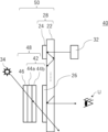
- FIG. 2 is a side view conceptually showing an example of an image display device using the second optical member.
- 2 is used as AR glasses as a suitable example.
- the second optical member can also be used as an optical element such as a transparent screen, a lighting device (including a backlight for a liquid crystal display), and a sensor, in addition to the AR glasses.
- the image display device 40 shown in FIG. 2 has an optical member 50 including an optical film 48 having a polarization control layer 42 and a light absorbing anisotropic layer 46, and a light guide member 28 arranged on the side of the optical film 48 having the polarization control layer 42, and a display element 32.
- the configuration of the image display device 40 shown in FIG. 2 is the same as that of the image display device 10 shown in FIG. 1, except that the optical film 12 in the image display device 10 shown in FIG. 1 is changed to the optical film 48. Therefore, only the configuration and function of the optical member 50 will be described below.
- the optically absorptive anisotropic layer 46 has an angle of 0 to 45° between the transmittance central axis of the optically absorptive anisotropic layer 46 and the normal direction of the optically absorptive anisotropic layer 46.
- the optically absorptive anisotropic layer 46 typically contains a dichroic material, and the direction of the absorption axis of the dichroic material (the long axis direction of the molecule) is approximately the same as the transmittance central axis of the optically absorptive anisotropic layer 46.
- the angle between the slow axis (in-plane slow axis) of the second ⁇ /4 film 44b and the horizontal direction is preferably set to 0 to 45°, more preferably set to 0 to 20°, and even more preferably set to 0 to 10°.
- the angle between the slow axis (in-plane slow axis) of the first ⁇ /4 film and the horizontal direction when the optical member is arranged in a usage form means the angle between the slow axis (in-plane slow axis) of the first ⁇ /4 film and the horizontal direction when a head-mounted display (e.g., an image display device such as AR glasses) including the optical member is used.
- the above angle means the angle between the slow axis (in-plane slow axis) of the first ⁇ /4 film and the horizontal direction when a user properly wears a head-mounted display such as the image display device 40 and uses it properly under normal conditions.
- the optical film 48 in the second optical member has the advantage that, compared to the optical film 12 in the first optical member, the azimuth angle width at which the degree of circular polarization in the direction perpendicular to the normal to the optical film 48 is 50% or more is wider than that of the optical film 12 in the first optical member.
- the optical film 48 has a degree of circular polarization of 50% or more in at least one azimuth angle direction that forms an angle of 60° with the normal direction of the optical film 48.
- the degree of circular polarization is 50% or more in at least one azimuth angle direction.
- the upper limit of the degree of circular polarization is not particularly limited, but is 100% or less.
- the degree of circular polarization is measured by irradiating light from the light absorption anisotropic layer side.
- the transmittance in the normal direction of the optical film 48 is 55% or more.
- the upper limit of the transmittance in the normal direction of the optical film 48 is not particularly limited, but is 100% or less.
- the transmittance is 25% or more in a direction that forms an angle of 30° with the normal direction of the optical film 48. In other words, the transmittance is 25% or more when light is incident at an inclination that forms a polar angle of 30° with respect to the normal direction of the optical film 48.
- the upper limit of the transmittance in a direction that forms an angle of 30° with the normal direction of the optical film 48 is not particularly limited, but is 100% or less.
- the transmittance is measured by irradiating light from the light absorption anisotropic layer side.
- the above transmittance can be achieved by setting the angle between the transmittance central axis of the light absorptive anisotropic layer 46 and the normal direction of the light absorptive anisotropic layer 46 to 0 to 45° and by appropriately adjusting the layer structure of the optical film 48.
- external light (light incident from the light source 34 in an oblique direction on the image display device 40) incident from above the head of the user U passes through the light absorption anisotropic layer 46 to become linearly polarized light vibrating in a predetermined direction, and is then incident on the polarization control layer 42 to be converted into right-handed or left-handed circularly polarized light (however, circularly polarized light having a polarization direction with low diffraction efficiency or no diffraction in the output diffraction element 26).
- the light selectively diffracted by the output diffraction element 26 is right-handed circularly polarized light, it is converted into left-handed circularly polarized light by the polarization control layer 42.
- the light transmitted through the polarization control layer 42 is irradiated to the light guide member 28, but since the light is circularly polarized light with low diffraction efficiency or a polarization direction with no diffraction in the output diffraction element 26, diffraction by the output diffraction element 26 is suppressed, and the light is less likely to enter the eyes of the user U. In other words, as a result of this, deterioration of the visibility of the background caused by external light incident from above the head of the user U can be suppressed.
- the rotation direction of the more abundant component of the right-handed circularly polarized light and the left-handed circularly polarized light emitted through the optical member is opposite to the rotation direction of the circularly polarized light diffracted by the diffraction element. More specifically, it is preferable that the rotation direction of the more abundant component of the right-handed circularly polarized light and the left-handed circularly polarized light emitted through the optical film in a direction in which the angle with the normal direction of the optical film is 60° and the degree of circular polarization is 50% or more is opposite to the rotation direction of the circularly polarized light diffracted by the diffraction element.
- the optical film 48 may be arranged so as to overlap at least a portion of the output diffraction element 26 when viewed from a direction perpendicular to the main surface of the light guide plate 22, but it is preferable that the optical film 48 is arranged so as to cover the entire surface as shown in FIG. 2.
- the optical film 48 is disposed apart from the light guide member 28, but is not limited to the above configuration, and the optical film 48 may be disposed in contact with the light guide member 28.
- the light-guiding member 28 is configured to have an input diffraction element 24 and an output diffraction element 26 on the main surface of the light-guiding plate 22, but the light-guiding member 28 may also be configured to further have an intermediate diffraction element.
- the light-guiding member 28 is a light-guiding member that has reflective diffraction elements (incident diffraction element 24 and exit diffraction element 26) on the main surface of the light-guiding plate, but the light-guiding member may also be a light-guiding member that has an incident diffraction element and an exit diffraction element, which are transmissive diffraction elements, on the main surface of the light-guiding plate.
- the polarization control layer 42 has a two-layer structure of the first ⁇ /4 film 44a and the second ⁇ /4 film 44b, but the polarization control layer 42 may have another optically anisotropic layer between the first ⁇ /4 film 44a and the second ⁇ /4 film 44b.
- An example of the other optically anisotropic layer is a positive C plate.
- the third optical member of the present invention is an optical film having a polarization control layer and a light absorption anisotropic layer; a light guide plate disposed on a side of the optical film having the polarization control layer, the light guide plate having a diffraction element whose diffraction efficiency changes depending on the polarization direction, the angle between the transmittance central axis of the optically absorptive anisotropic layer and the normal direction of the optically absorptive anisotropic layer is 0 to 45°;
- the optical film has a degree of circular polarization of 50% or more in at least one azimuth angle direction at an angle of 60° with respect to a normal direction of the optical film, a transmittance of 55% or more in the normal direction of the optical film, and a transmittance of 25% or more in the direction at an angle of 30° with respect to the normal direction of the optical film,
- the polarization control layer is one or more layers containing a liquid crystal compound having a
- the image display device includes the third optical member and a display element that projects an image onto the incident diffraction element in the third optical member.
- FIG. 3 is a side view conceptually showing an example of an image display device using the third optical member.
- 3 is used as AR glasses as a suitable example.
- the third optical member can also be used as an optical element such as a transparent screen, a lighting device (including a backlight for a liquid crystal display), and a sensor, in addition to the AR glasses.
- the image display device 60 shown in FIG. 3 has an optical member 68 including an optical film 62 having a polarization control layer 64 and a light absorbing anisotropic layer 66, and a light guide member 28 arranged on the side of the optical film 62 having the polarization control layer 64, and a display element 32.
- the configuration of the image display device 60 shown in FIG. 3 is the same as that of the image display device 10 shown in FIG. 1, except that the optical film 12 in the image display device 10 shown in FIG. 1 is changed to the optical film 62. Therefore, only the configuration and function of the optical member 68 will be described below.
- the optical member 68 has an optical film 62 having a polarization control layer 64 and a light absorbing anisotropic layer 66.
- the optical film 62 is disposed on the side opposite the light guide plate 22 side of the output diffraction element 26.
- the optical film 62 is disposed on the side opposite the output side of the output diffraction element 26.
- the optical film 62 is also disposed in a position overlapping with the output diffraction element 26 in the planar direction of the main surface of the light guide plate 22 so that the polarization control layer 64 faces the output diffraction element 26.
- the optically absorbing anisotropic layer 66 has an angle of 0 to 45° between the central axis of transmittance of the optically absorbing anisotropic layer 66 and the normal direction of the optically absorbing anisotropic layer 66.
- the optically absorbing anisotropic layer 66 typically contains a dichroic material, and the direction of the absorption axis of the dichroic material (the long axis direction of the molecule) is approximately the same as the central axis of transmittance of the optically absorbing anisotropic layer 66. In other words, in the optically absorbing anisotropic layer 66, the dichroic material is oriented so that its absorption axis is approximately perpendicular to the main surface.
- the polarization control layer 64 is a layer (hereinafter also referred to as a "twist layer”) that contains one or more liquid crystal compounds having a twist structure. More specifically, the twist layer is a layer in which liquid crystal compounds are fixed that are twisted and oriented along a helical axis extending in the thickness direction (the twist angle of the liquid crystal compounds is typically 360° or less, and preferably less than 360°), and has the function of rotating linearly polarized light that is incident perpendicularly to the plane of the twist layer.
- the angle between the slow axis (in-plane slow axis) of the twist layer on the light absorption anisotropic layer 62 side and the horizontal direction when the optical member is arranged in a usage form means the angle between the slow axis (in-plane slow axis) of the twist layer on the light absorption anisotropic layer 62 side and the horizontal direction when a head-mounted display (e.g., an image display device such as AR glasses) including the optical member is used. More specifically, the above angle means the horizontal direction in a situation where a user properly wears a head-mounted display such as the image display device 60 and uses it properly under normal circumstances.
- a head-mounted display e.g., an image display device such as AR glasses
- the optical film 62 has a degree of circular polarization of 50% or more in at least one azimuth angle direction that forms an angle of 60° with the normal direction of the optical film 62.
- the degree of circular polarization is 50% or more in at least one azimuth angle direction.
- the upper limit of the degree of circular polarization is not particularly limited, but is 100% or less.
- the degree of circular polarization is measured by irradiating light from the light absorption anisotropic layer side.
- the optical film 62 has a degree of circular polarization of 50% or more in the direction that forms an angle of 60° with the normal direction of the optical film 62 in at least one azimuth angle, as described below, the light that passes through the polarization control layer 64 and is irradiated to the light-guiding member 28 is less likely to be diffracted, and the visibility of the background caused by external light entering from above the user U's head is excellent.
- the circular polarization degree of the optical film 62 is more preferably 60 to 100%, and even more preferably 75 to 100%, in that the visibility of the background caused by external light entering from above the user U is superior.
- the above transmittance can be achieved by setting the angle between the transmittance central axis of the light absorptive anisotropic layer 66 and the normal direction of the light absorptive anisotropic layer 66 to be 0 to 45° and by appropriately adjusting the layer structure of the optical film 62.
- external light (light incident from the light source 34 in an oblique direction on the image display device 60) incident from above the head of the user U passes through the light absorption anisotropic layer 66 to become linearly polarized light vibrating in a predetermined direction, and is then incident on the polarization control layer 64 to be converted into right-handed or left-handed circularly polarized light (however, circularly polarized light having a polarization direction with low diffraction efficiency or no diffraction in the output diffraction element 26).
- the rotation direction of the more abundant component of the right-handed circularly polarized light and the left-handed circularly polarized light emitted through the optical member is opposite to the rotation direction of the circularly polarized light diffracted by the diffraction element. More specifically, it is preferable that the rotation direction of the more abundant component of the right-handed circularly polarized light and the left-handed circularly polarized light emitted through the optical film in a direction in which the angle with the normal direction of the optical film is 60° and the degree of circular polarization is 50% or more is opposite to the rotation direction of the circularly polarized light diffracted by the diffraction element.
- the polarization control layer 64 is a twist layer having a single layer structure, but the polarization control layer 64 may have a structure in which two or more twist layers are laminated, or may further have another optically anisotropic layer on the opposite side of the twist layer to the light absorption anisotropic layer.
- An example of the other optically anisotropic layer is a positive C plate.
- the polarization control layer used in the optical member of the present invention is a layer that can polarize and control linearly polarized light that is incident obliquely to the plane of the polarization control layer into circularly polarized light.
- the linearly polarized light can be more circularly polarized when the light is incident from an oblique direction that forms an angle of 40° or more with the normal direction of the polarization control layer.
- Typical examples of the polarization control layer that circularly polarizes linearly polarized light include a ⁇ /4 film and a twist layer.
- the ⁇ /4 film used in the optical member of the present invention refers to a retardation layer having an in-plane retardation of about 1 ⁇ 4 of the wavelength, specifically, a retardation layer having an in-plane retardation Re(550) of 100 nm to 180 nm at a wavelength of 550 nm.
- the Rth of the ⁇ /4 film used in the optical member of the present invention is preferably ⁇ 200 nm to 400 nm.
- the ⁇ /4 film used in the optical component of the present invention is not particularly limited as long as the in-plane retardation is approximately 1/4 of the wavelength, but it is preferable that the film is a layer formed using a composition containing a liquid crystal compound.
- liquid crystal compounds can be classified into rod-shaped and disc-shaped types based on their shape. Furthermore, there are low molecular weight and high molecular weight types. High molecular weight generally refers to a compound with a degree of polymerization of 100 or more (Polymer Physics, Phase Transition Dynamics, Masao Doi, p. 2, Iwanami Shoten, 1992). In the optical member of the present invention, any liquid crystal compound can be used, but rod-shaped liquid crystal compounds or discotic liquid crystal compounds (discotic liquid crystal compounds) are preferred. In addition, liquid crystal compounds that are monomers or have a relatively low molecular weight with a degree of polymerization of less than 100 are preferred.
- azomethines As rod-shaped liquid crystal compounds, azomethines, azoxys, cyanobiphenyls, cyanophenyl esters, benzoates, cyclohexane carboxylic acid phenyl esters, cyanophenylcyclohexanes, cyano-substituted phenylpyrimidines, alkoxy-substituted phenylpyrimidines, phenyldioxanes, tolanes, and alkenylcyclohexylbenzonitriles are preferably used.
- Disc-shaped liquid crystal compounds include benzene derivatives described in the research report by C. Destrade et al., Mol. Cryst., Vol. 71, p. 111 (1981), truxene derivatives described in the research report by C. Destrade et al., Mol. Cryst., Vol. 122, p. 141 (1985) and Physicslett, A, Vol. 78, p. 82 (1990), cyclohexane derivatives described in the research report by B. Kohne et al., Angew. Chem., Vol. 96, p. 70 (1984), and cyclohexane derivatives described in the research report by J. M. Lehn et al., J.
- the molecules of the discotic liquid crystal compound include compounds that exhibit liquid crystallinity in which linear alkyl groups, alkoxy groups, and substituted benzoyloxy groups are substituted radially as side chains of the mother nucleus at the center of the molecule. It is preferable that the molecule or molecular aggregate is a compound that has rotational symmetry and can impart a certain orientation.
- the retardation layer formed from a composition containing a discotic liquid crystal compound does not necessarily exhibit liquid crystallinity when it is finally included in the retardation layer.
- discotic liquid crystal molecules having a group that reacts with heat or light when they are polymerized by heating or light irradiation to increase the molecular weight, they lose their liquid crystallinity, but the retardation layer containing such a high-molecular compound can of course be used in the optical element of the present invention.
- Preferred examples of discotic liquid crystal compounds include the compounds described in JP-A-8-050206.
- the polymerization of discotic liquid crystal molecules is described in JP-A-8-027284.
- the liquid crystal compound may have forward or reverse wavelength dispersion.
- C Plate There are two types of C plates used in the optical member of the present invention: a positive C plate (positive C plate, +C plate) and a negative C plate (negative C plate, -C plate).
- the positive C plate satisfies the relationship of formula (C1)
- the negative C plate satisfies the relationship of formula (C2).
- the positive C plate has a negative Rth value
- the negative C plate has a positive Rth value.
- Formula (C2) nz ⁇ nx ⁇ ny
- ⁇ includes not only the case where the two are completely identical, but also the case where the two are substantially identical.
- nx-nyxd is 0 to 10 nm, preferably 0 to 5 nm, as "nx ⁇ ny.”
- d is the thickness of the film.
- the Rth of the C plate used in the optical component of the present invention is preferably -500 nm to -10 nm, or 10 nm to 500 nm.
- the twist layer used in the optical member of the present invention is a layer formed by fixing liquid crystal compounds that are twisted and aligned along a helical axis extending in the thickness direction.
- the twist layer is an optical element having optical rotation. Having optical rotation means that linearly polarized light rotates and propagates through the medium while remaining approximately linearly polarized. Therefore, the twist layer has the function of rotating linearly polarized light that is incident perpendicularly to the plane of the twist layer.
- the twist angle of the liquid crystal compound in the twist layer is not particularly limited, but is preferably 20 to 360.degree.. The twist angle is measured using an AxoScan (polarimeter) device manufactured by Axometrics Inc. and the device analysis software of the same company.
- the refractive index anisotropic layer having a twist structure is preferably a film having a twist structure formed by adding a chiral material to a rod-shaped or disc-shaped liquid crystal compound.
- it can be made thinner than a phase difference using a polymer.
- it is difficult to manufacture multiple polymer films by laminating the slow axis of the polymer film in-plane while changing the angle little by little in order to obtain a twist structure and optical rotation.
- the polymer film a cellulose acylate-based film, a cycloolefin-based polymer film (a polymer film using a cycloolefin-based polymer), a polycarbonate-based polymer film, a polystyrene-based polymer film, or an acrylic-based polymer film is preferable.
- the acrylic polymer film it is preferable to include an acrylic polymer containing at least one unit selected from a lactone ring unit, a maleic anhydride unit, and a glutaric anhydride unit.
- the light absorbing anisotropic layer contains a dichroic dye, and the absorption axis of the dichroic dye forms an angle of 0 to 45° with the normal to the main surface.
- the transmittance is high when viewed from the front, but is low when viewed from an oblique direction because only S-polarized light passes through.
- the absorption axis of the optically absorptive anisotropic layer parallel to the main surface it is possible to obtain an optically absorptive anisotropic layer having optical properties similar to those of an iodine-based polarizer, which is generally known to be formed by impregnating a PVA (polyvinyl alcohol) stretched film with polyiodine ions.
- PVA polyvinyl alcohol
- the absorption axis of the optically absorptive anisotropic layer is oriented in a direction approximately perpendicular to the main surface (horizontal reference plane) can be confirmed, for example, by observing a cross section of the optically absorptive anisotropic layer with a transmission electron microscope (TEM (Transmission Electron Microscope)).
- TEM Transmission Electron Microscope
- Techniques for orienting the dichroic dye in a desired direction can be based on techniques for producing polarizers using dichroic dyes and techniques for producing guest-host liquid crystal cells.
- the techniques used in the method for producing a dichroic polarizing element described in JP-A-2002-090526 and the method for producing a guest-host type liquid crystal display device described in JP-A-2002-099388 can also be used in the production of the light absorption anisotropic layer used in the optical member of the present invention.
- examples of azo dyes include those described in JP-A-11-172252
- examples of anthraquinone dyes include those described in JP-A-8-067822
- examples of perylene dyes include those described in JP-A-62-129380
- examples of mericiane dyes include those described in JP-A-2002-241758. These may be used alone or in combination of two or more.
- dichroic dyes having discotic molecules include lyotropic liquid crystals such as those from “OPTIVA Inc.”, which are known to be used as "E-Type polarizers.”
- materials described in JP-A-2002-090547 can be mentioned.
- a bis-azo dichroic dye that utilizes a string-like micelle type structure as a chemical structure that absorbs light in a disc shape examples of such a material include those described in JP-A-2002-090526. These may be used alone or in combination of two or more.
- an "E-Type polarizer" using a disc-shaped dichroic dye it is possible to block oblique external light without combining it with a polarizer whose absorption axis is within the principal plane.
- rod-shaped dichroic dyes are preferred because they are easier to achieve a high degree of orientation.
- the molecules of a dichroic dye can be aligned in a desired direction as described above in association with the alignment of the host liquid crystal.
- a light absorbing anisotropic layer can be produced by mixing a dichroic dye as a guest with a rod-shaped liquid crystal compound as a host liquid crystal, orienting the host liquid crystal, and orienting the dichroic dye molecules along the orientation of the liquid crystal molecules, and fixing the orientation state.
- the alignment of the dichroic dye can be fixed by promoting polymerization of the host liquid crystal, the dichroic dye, or a polymerizable component that is added as desired.
- a guest-host type liquid crystal cell having a liquid crystal layer containing at least a dichroic dye and a host liquid crystal between a pair of substrates may itself be used as the light absorbing anisotropic layer.
- the orientation of the host liquid crystal and the associated orientation of the dichroic dye molecules can be controlled by an orientation film formed on the inner surface of the substrate. The orientation state is maintained unless an external stimulus such as an electric field is applied, and the light absorption characteristics of the light absorption anisotropic layer can be made constant.
- a polymer film that satisfies the light absorption characteristics required for the light absorption anisotropic layer can be prepared by permeating a dichroic dye into a polymer film and orienting the dichroic dye along the orientation of the polymer molecules in the polymer film.
- the polymer film can be prepared by applying a solution of the dichroic dye onto the surface of the polymer film and permeating the film.
- the orientation of the dichroic dye can be adjusted by the orientation of the polymer chain in the polymer film, the properties of the polymer chain, the coating method, etc.
- the properties of the polymer chain refer to the chemical and physical properties of the polymer chain or the functional groups that the polymer chain has. Details of this method are described in JP-A-2002-090526.
- a dichroic dye (dichroic substance) is defined as a compound having the function of absorbing light.
- the dichroic dye may have any absorption maximum and absorption band, but preferably has an absorption maximum in any of the yellow region (Y), magenta region (M), and cyan region (C). Two or more kinds of dichroic dyes may be used. It is preferable to use a mixture of dichroic dyes having an absorption maximum in any one of Y, M, and C, and it is more preferable to use a mixture of dichroic dyes so as to absorb the entire visible range (400 to 750 nm).
- the yellow region is a wavelength range of 430 to 500 nm
- the magenta region is a wavelength range of 500 to 600 nm
- the cyan region is a wavelength range of 600 to 750 nm.
- the thickness of the optically absorptive anisotropic layer is preferably 0.1 to 10 ⁇ m, more preferably 0.3 to 5 ⁇ m, and even more preferably 0.5 to 3 ⁇ m.
- the method for producing the light absorption anisotropic layer is not particularly limited as long as it can align the dichroic dye so that the major axis of the dichroic dye is perpendicular to the substrate surface (horizontal surface), and can be appropriately selected depending on the purpose.
- Examples of the method include (1) a guest-host liquid crystal method, (2) anodized alumina method, (3) control of the surface energy of the substrate, and (4) use of a surfactant.
- the guest-host liquid crystal method (1) is a method in which an absorbing layer coating liquid containing at least a UV-curable liquid crystal compound and a dichroic dye is applied to a substrate having an alignment film on its surface, and then dried to form a coating layer.
- the coating layer is heated to a temperature at which a liquid crystal phase appears, and then irradiated with UV light to form a light absorbing anisotropic layer in which the long axis of the dichroic dye is oriented approximately perpendicular to the substrate surface.
- the central axis of transmittance of the optically absorptive anisotropic layer means the direction showing the highest transmittance when the transmittance is measured by changing the inclination angle (polar angle) and inclination direction (azimuth angle) relative to the normal direction of the optically absorptive anisotropic layer surface.
- the Mueller matrix at a wavelength of 550 nm is measured using AxoScan OPMF-2 (manufactured by Axometrics).
- the azimuth angle at which the transmittance central axis is tilted is first found, and then, within a plane including the normal direction of the optically absorptive anisotropic layer along that azimuth angle (a plane including the transmittance central axis and perpendicular to the layer surface), the polar angle, which is the angle with respect to the normal direction of the optically absorptive anisotropic layer surface, is changed from -70 to 70° in 1° increments, and the Mueller matrix at a wavelength of 550 nm is measured, and the transmittance of the optically absorptive anisotropic layer is derived.
- the central axis of transmittance means the direction of the absorption axis (the direction of the long axis of the molecule) of the dichroic material contained in the light absorption anisotropic layer.
- the optical film may include a polarizer.
- the polarizer has an absorption axis that is in the main plane, that is, the absorption axis of the polarizer is parallel to the main plane.
- the optical film acts like a polarizer arranged in crossed Nicols with respect to oblique external light I s , and therefore can suitably block (absorb) the oblique external light I s .
- polarizers having an absorption axis parallel to the principal surface examples of which include an iodine-based polarizer in which a stretched PVA film is impregnated with polyiodine ions, a dye-based polarizer in which a stretched PVA film is impregnated with a dichroic dye, and the above-mentioned light absorption anisotropic layer exhibiting optical performance in which the absorption axis of the light absorption anisotropic layer is oriented parallel to the principal surface.
- the optical film may further include a retardation layer.
- a retardation layer By providing the optical film with a retardation layer, the polarization direction of the oblique external light I s can be adjusted, and the optical film can more suitably block the oblique external light I s .
- the optical film by providing the optical film with a retardation layer, visibility problems caused by external light incident from diagonally forward above the head (diagonally forward above the head) can be suppressed.
- the optical film may further include, as necessary, a protective layer, an oxygen barrier layer, an adhesive layer such as a pressure-sensitive adhesive layer, an adhesive layer, an ultraviolet absorbing layer, and a layer that absorbs specific visible light such as a blue light absorbing layer.
- the light guide plate is a known light guide plate that reflects and guides (propagates) light that has entered the interior.
- the light guide plate There is no particular limitation on the light guide plate, and various known light guide plates used in AR glasses, backlight units of liquid crystal displays, etc. can be used.
- a polarizing diffraction element As the diffraction elements (for example, the entrance diffraction element, the intermediate diffraction element, and the exit diffraction element) used in the optical member of the present invention, a polarizing diffraction element can be used.
- a known polarizing diffraction element can be used as the polarizing diffraction element.
- the polarizing diffraction element is a diffraction element that controls the diffraction direction, polarization state, and diffracted light intensity of the output light according to the polarization state of the incident light by controlling the polarization state in a fine region.
- the polarizing diffraction element is a diffraction element whose diffraction efficiency changes depending on the polarization direction.
- the polarizing diffraction element is preferably an element that diffracts circularly polarized light.
- various known diffraction elements such as a diffraction element formed by using structural birefringence such as a relief type diffraction element and a volume hologram diffraction element, and a liquid crystal diffraction element can be used.
- a suitable example of the liquid crystal diffraction element is a liquid crystal diffraction element formed by using a composition containing a liquid crystal compound and having a liquid crystal orientation pattern in which the direction of the optical axis derived from the liquid crystal compound changes while continuously rotating along at least one direction in the plane.
- Another suitable example of the liquid crystal diffraction element is a diffraction element having a cholesteric liquid crystal layer formed by fixing a cholesteric liquid crystal phase.
- a liquid crystal diffraction element As a diffraction element whose diffraction efficiency changes depending on the polarization direction, a liquid crystal diffraction element is particularly preferable.
- a liquid crystal diffraction element for example, the liquid crystal diffraction elements described in paragraphs [0070] to [0143] of International Publication No. 2021/106749 can also be preferably used.
- the slit direction refers to the direction of a structure that generates diffraction in a diffraction element (diffraction grating).
- structures that generate diffraction include grooves, protrusions, boundaries with different liquid crystal orientation structures, boundaries with different refractive indices, boundaries with different transmittances, etc.
- the diffraction element is a diffraction element having a physical groove shape, such as a surface relief type diffraction element or a holographic surface diffraction element
- the extension direction (longitudinal direction) of the groove portion forming the diffraction element is the slit direction.
- the diffraction element is a diffraction element having a high refractive index region and a low refractive index region, such as a transmission type volume phase holographic diffraction element
- the extension direction of the boundary between the high refractive index region and the low refractive index region is the slit direction.
- the diffraction element is a liquid crystal diffraction element
- the direction in which the orientation direction of the liquid crystal compound is uniform in any plane in the thickness direction of the diffraction element is the slit direction. For example, as described in FIG.
- External light that is obliquely incident on the diffraction element of the AR glasses is often external light that is incident on the AR glasses from above (especially from above and in front), such as sunlight and indoor lighting.
- this external light is diffracted by the diffraction element and reaches the user's viewing position, it is likely to cause visibility problems.
- a diffraction element whose slit direction is close to the horizontal direction is likely to diffract external light incident from above (particularly from above and in front) through the light guide plate toward the user's observation position. Therefore, when the optical member of the present invention has multiple diffraction elements, it is preferable to provide an optical film at least on the diffraction element whose slit direction is closest to the horizontal direction.
- the first to third optical members are preferably applied to a head mounted display (for example, an image display device such as AR glasses), and more preferably applied to AR glasses.
- the image display device of the present invention is typically configured to include the above-mentioned optical member (any of the first to third optical members) and a display element that projects an image onto the incident diffraction element of the optical member.
- the display element displays an image (video) observed by a user U and projects the image onto the incident diffraction element. Therefore, the display element is disposed so that the projected image is incident on the incident diffraction element.
- Various members of the image display device will be described below.
- the optical member may be any one of the first to third optical members described above.
- the image display device has a plurality of optical members
- a display that displays a multi-color image using light of a wavelength diffracted by each diffractive element of each optical member is used.
- a known projection lens (collimator lens) used in AR glasses or the like can be used as the projection lens.
- the image displayed by the display element (that is, the light irradiated by the display element) is not particularly limited, but is preferably unpolarized (natural light) or circularly polarized light.
- the display element irradiates circularly polarized light and the display irradiates an unpolarized image
- the display element preferably has a circular polarizing plate, for example, made of a linear polarizer and a ⁇ /4 plate.
- the display element When the display irradiates a linearly polarized image, the display element preferably has a ⁇ /4 plate. Note that the light irradiated by the display element may be other polarized light (for example, linearly polarized light, etc.).
- composition for forming alignment film 1 Polymer PA-1 (listed below) 100.00 parts by weight Acid generator PAG-1 (listed below) 8.25 parts by weight Stabilizer DIPEA (listed below) 0.6 parts by weight Butyl acetate 1001.42 parts by weight Methyl ethyl ketone 250.36 parts by weight Club------------------------------------------------------------------------------------------------------------------------------------------------------------------------------------------------------------------------------------------------------------------------------------------------------------------------------------------------------------------------------------------------------------------------------------------------------------------------------------------------------------------------------------------
- Polymer PA-1 (wherein the numerical value for each repeating unit represents the content (mass%) of each repeating unit relative to the total repeating units.)
- optically absorptive anisotropic layer 1 had a thickness of 4.5 ⁇ m.
- the film provided with the optically absorptive anisotropic layer 1 prepared above will also be referred to as "optically absorptive anisotropic film 1.”
- the optically absorptive anisotropic film 1 produced in the upper section was placed horizontally on the sample stage, and the transmittance was measured using AxoScan OPMF-2 (manufactured by Axometrics) while varying the azimuth angle and polar angle at which light was incident on this film as described above, to determine the azimuth angle and polar angle of the central axis of transmittance of the optically absorptive anisotropic layer 1.
- the central axis of transmittance of the optically absorptive anisotropic layer 1 was in the direction of a polar angle of 0°.
- composition P1 ⁇ 0.69 parts by weight of the dichroic substance D-1 shown below 0.17 parts by weight of the dichroic substance D-2 shown below 1.13 parts by weight of the dichroic substance D-3 shown below
- Polymer liquid crystal compound P- 1 8.67 parts by weight; Liquid crystal compound L-1 shown below 1.97 parts by weight; IRGACURE OXE-02 (manufactured by BASF) 0.20 parts by weight; Alignment agent E-1 shown below 0.16 parts by weight; Alignment agent E shown below -2 0.16 parts by mass; Surfactant F-2 (see below) 0.007 parts by mass; Cyclopentanone 78.17 parts by mass; Benzyl alcohol 8.69 parts by mass --------------------------------------------------------------------------------------------------------------------------------------------------------------------------------------------------------------------------------------------
- Polymeric liquid crystal compound P-1 (wherein the numerical value for each repeating unit in the main chain represents the content (mass %) of each repeating unit relative to all repeating units)
- Liquid crystal compound L-1 [a mixture of the following liquid crystal compounds (RA), (RB), and (RC) in a mass ratio of 84:14:2]
- Surfactant F-2 (wherein the numerical value for each repeating unit represents the content (mass%) of each repeating unit relative to the total repeating units.)
- TMS stands for trimethylsilyl group.
- composition B1 ⁇ 3.80 parts by mass of the following modified polyvinyl alcohol PVA-1 Omnirad 2959 (IGM Resins B.V.) 0.20 parts by mass, dye compound G-1 (see below) 0.08 parts by mass, water 70 parts by mass, methanol 30 parts by mass ------------------------------------------------------------------------------
- Modified polyvinyl alcohol PVA-1 (wherein the numerical value for each repeating unit represents the content (mass%) of each repeating unit relative to the total repeating units.)
- reaction solution After cooling the reaction solution to room temperature (23° C.), the reaction solution was subjected to suction filtration to remove the precipitated salt.
- the obtained organic layer was transferred to a 2 L three-neck flask equipped with a stirring blade, a thermometer, a dropping funnel, and a reflux condenser, and stirred under water cooling.
- reaction solution was allowed to cool to room temperature, and 2-butanone (30 parts by mass) was added to the reaction solution to dilute it, thereby obtaining a polymer solution with a polymer concentration of about 20% by mass.
- the obtained polymer solution was poured into a large excess of methanol to precipitate the polymer, the precipitate was filtered, and the obtained solid was washed with a large amount of methanol, and then dried by blowing air at 50 ° C. for 12 hours to obtain a polymer P-1 having a photoalignment group.
- composition for photoalignment film was prepared as follows. ⁇ Photoalignment film composition 3 ⁇ ⁇ Polymer P-1 above 100.00 parts by mass ⁇ Thermal acid generator D-1 below 3.00 parts by mass ⁇ Diisopropylethylamine 0.60 parts by mass ⁇ Butyl acetate 953.12 parts by mass ⁇ Methyl ethyl ketone 238.28 parts by mass
- the prepared photoalignment film composition 3 was placed in a glass bottle and stored in a sealed state at room temperature for 7 days.
- composition 3 for photo-alignment film stored for 7 days was applied to one side of a 40 ⁇ m-thick cellulose acylate film (TAC substrate; Fujifilm Corporation, TG40) using a bar coater.
- TAC substrate 40 ⁇ m-thick cellulose acylate film
- the film coated with the composition 3 for photo-alignment film was then dried on a hot plate at 125° C. for 2 minutes to remove the solvent, forming a precursor film with a thickness of 0.15 ⁇ m.
- the obtained precursor film was irradiated with polarized ultraviolet light (8 mJ/cm 2 , using an ultra-high pressure mercury lamp) to form the photo-alignment film 3.
- the following retardation layer coating solution B was applied onto the photo-alignment film 3 using a bar coater.
- the coating film formed on the photo-alignment film 3 was heated to 120°C with hot air, and then cooled to 60°C. After that, the coating film was irradiated with 100 mJ/ cm2 ultraviolet light at a wavelength of 365 nm using a high-pressure mercury lamp under a nitrogen atmosphere, and then irradiated with 500 mJ/ cm2 ultraviolet light while heating to 120°C.
- the above procedure fixed the orientation of the liquid crystal compound to prepare a ⁇ /4 layer.
- the obtained laminate (cellulose acylate film/photo-alignment film 3/ ⁇ /4 layer) had Re(550) of 140 nm and Rth(550) of 80 nm, and was a ⁇ /4 film.
- Surfactant F-3 (wherein the numerical value attached to each repeating unit in the main chain indicates the content (mass%) of each repeating unit relative to all repeating units.)
- the optical film 1 produced in the upper part was measured for transmittance and degree of circular polarization by measuring the Mueller matrix at a wavelength of 550 nm using AxoScan OPMF-2 (manufactured by Axometrics). Specifically, using the measurement mode "Arbitrary Field-of-View" of AxoScan, light was irradiated from the light absorption anisotropic layer side under measurement angle conditions of polar angles of 0°, 30°, and 60°, and azimuth angles at 5° intervals. The results are shown in Table 1. It was also found that the light incident from the polar angle direction of 60° was left-handed circularly polarized light.
- a light guide plate (light guide member) having a liquid crystal diffraction element arranged thereon A light guide plate (light guide member) in which a liquid crystal diffraction element was arranged was produced in the same manner as in Comparative Example 5 described in International Publication No. 2021/106749. It was confirmed that the produced liquid crystal diffraction element was diffracted when irradiated with right-handed circularly polarized light.
- optical member A1 The optical film 1 produced in the upper part and the light guide member produced in the upper part were stacked to produce the optical member A1. At this time, the optical member A1 was arranged so that the angle between the slow axis (in-plane slow axis) of the ⁇ /4 film included in the optical film 1 and the horizontal direction was 10° when the optical member A1 was in a usable state.
- the layer structure of the optical member A1 was in the order of "lightly absorbing anisotropic layer 1/ ⁇ /4 film/light guiding member" as shown in the table.
- the optical film 1 was disposed on the side of the light guiding member opposite to the light guiding plate (in other words, the side having the exit diffraction element (liquid crystal diffraction element)) at a position overlapping with the exit diffraction element (liquid crystal diffraction element) in the planar direction.
- Example 2 (Preparation of Optical Member A2)] [Preparation of Optical Film 2]
- An optical member A2 of Example 2 was produced by the following procedure.
- the optical member A2 corresponds to the second optical member described in the upper part.
- the surface of the laminate 1 prepared in the upper part on which the protective layer B1 was formed and the surface of the ⁇ /4 layer of the above-mentioned ⁇ /4 film were laminated together using a commercially available adhesive (SK2057, manufactured by Soken Chemical Industries, Ltd.), and then the cellulose acylate film (TG40, manufactured by Fujifilm Corporation), which is a support member of the ⁇ /4 layer in the obtained laminate, was peeled off between the cellulose acylate film and the photo-alignment film.
- a commercially available adhesive SK2057, manufactured by Soken Chemical Industries, Ltd.
- TG40 cellulose acylate film
- the ⁇ /4 layer of the separately prepared ⁇ /4 film was laminated using a commercially available adhesive (SK2057, manufactured by Soken Chemical Industries, Ltd.) so that they faced each other. At this time, the two layers of ⁇ /4 layers were laminated so that the angle between the slow axes of the layers was 45°.
- the cellulose acylate film (TG40, manufactured by Fujifilm Corporation), which is a support member of the ⁇ /4 layer, was peeled off between the cellulose acylate film and the photo-alignment film from the ⁇ /4 film in the obtained laminate, to prepare an optical film 2.
- the transmittance and the degree of circular polarization were measured in the same manner as described in Example 1. The results are shown in Table 1.
- optical member A2 The optical film 2 produced in the upper section and the light guide member produced in the upper section were stacked to produce the optical member A2. At this time, the optical member A2 was arranged so that the slow axis (in-plane slow axis) of the ⁇ /4 film on the light guide plate side included in the optical film 2 was parallel to the horizontal direction (the angle between the in-plane slow axis and the horizontal direction was 0°) when the optical member A2 was in a use state.
- the layer structure of the optical member A2 was in the order of "lightly absorbing anisotropic layer 1 / ⁇ /4 film / ⁇ /4 film / light guide member" as shown in the table.
- the optical film 2 was arranged on the side opposite to the light guide plate (in other words, the side having the exit diffraction element (liquid crystal diffraction element)) of the position overlapping with the exit diffraction element (liquid crystal diffraction element) in the planar direction of the produced light guide member.
- Example 3 (Preparation of Optical Member A3)
- An optical member A3 of Example 3 was produced by the following procedure.
- the optical member A3 corresponds to the second optical member described in the upper part.
- An optical member A3 of Example 3 was produced by the following procedure.
- the optical member A3 corresponds to the second optical member described in the upper part.
- the surface of the laminate 1 prepared in the upper part on which the protective layer B1 was formed was bonded to the above-mentioned ⁇ /4 film 2 using a commercially available adhesive (SK2057, manufactured by Soken Chemical Engineering Co., Ltd.).
- a separately prepared ⁇ /4 film 2 was bonded to the already bonded ⁇ /4 film 2 side using a commercially available adhesive (SK2057, manufactured by Soken Chemical Engineering Co., Ltd.).
- the two ⁇ /4 films 2 were bonded so that the angle between the slow axes of the films was 45°, and an optical film 3 was prepared.
- the transmittance and the degree of circular polarization were measured in the same manner as described in Example 1. The results are shown in Table 1.
- An optical member A3 was prepared in the same manner as in the preparation of the optical member A2 in Example 2, except that the optical film 2 was changed to the optical film 3.
- Example 4 (Preparation of Optical Member A4)
- An optical member A4 of Example 4 was produced by the following procedure.
- the optical member A4 corresponds to the second optical member described in the upper part.
- [Preparation of C-plate 1] The following composition for forming C plate 1 was prepared to obtain a homogeneous solution.
- Discotic liquid crystal compound CA-1 (1,3,5-substituted benzene-type polymerizable discotic liquid crystal compound)
- Discotic liquid crystal compound CA-2 (1,3,5-substituted benzene-type polymerizable discotic liquid crystal compound)
- Discotic liquid crystal compound CB-1 polymerizable triphenylene type discotic liquid crystal compound
- Polymer CC-1 (hereinafter, the copolymerization ratios in the chemical structural formulas are shown in mass%.)
- a commercially available cellulose triacetate film (FUJITAC ZRD40, manufactured by FUJIFILM Corporation) was used after being subjected to a saponification treatment.
- the above-mentioned composition for forming C-plate 1 was applied to the surface of the support, the solvent was dried by a process of continuously heating from room temperature to 100°C, and the coating film was further heated for about 90 seconds in a drying zone at 100°C. Thereafter, the temperature was lowered to 60°C, and the coating film was cured by performing UV exposure of 300 mJ/ cm2 under the atmosphere to form a cured film.
- the obtained laminate film of the cured film and the support had an Re of 3 nm and an Rth of 180 nm.
- the laminate film was designated as C plate 1.
- optical member A4 The optical film 4 produced in the upper section and the light guide member produced in the upper section were stacked to produce the optical member A4. At this time, when the optical member A4 was in a use state, the slow axis (in-plane slow axis) of the ⁇ /4 film on the light guide plate side included in the optical film 4 was arranged parallel to the horizontal direction (the angle between the in-plane slow axis and the horizontal direction was 0°).
- the layer structure of the optical member A4 was in the order of "lightly absorbing anisotropic layer 1 / ⁇ /4 film / C plate / ⁇ /4 film / light guide member" as shown in the table.
- an optical film 4 was arranged on the side opposite to the light guide plate (in other words, the side having the exit diffraction element (liquid crystal diffraction element)) of the prepared light guide member at a position overlapping with the exit diffraction element (liquid crystal diffraction element) in the planar direction.
- Example 5 (Preparation of Optical Member A5)] An optical member A5 of Example 5 was produced by the following procedure. The optical member A5 corresponds to the third optical member described in the upper part.
- a peelable support was prepared by subjecting the surface of a 75 ⁇ m PET film (manufactured by Fuji Film Co., Ltd.) to a rubbing treatment. Onto the rubbed surface of the prepared peelable support, the following coating solution 1 for twist layer was applied using a bar coater so that the resulting coating film had a thickness of 3.4 ⁇ m to form a coating film.
- the coating was heated and aged for 90 seconds at a surface temperature of 60°C, and then irradiated with 300 mJ/ cm2 ultraviolet light at 100°C to fix the orientation of the liquid crystal compound and form a twist layer, thereby producing twist film 1 comprising a peelable support and a twist layer.
- the ⁇ nd of the liquid crystal compound in the obtained twisted layer was 550 nm.
- the twisted layer contained a liquid crystal compound that was twisted and aligned along a helical axis extending along the thickness direction.
- the twist angle of the helical liquid crystal compound was 255°.
- optical film 5 produced in the upper part and the light guide member produced in the upper part were overlapped to produce the optical member A5. At this time, the optical film 5 was arranged so that the angle between the slow axis (in-plane slow axis) of the twist layer on the light absorptive anisotropic layer 1 side and the horizontal direction was 25° when the optical member A5 was in a use state.
- the layer structure of the optical member A5 was in the order of "lightly absorbing anisotropic layer 1 / twist film 1 / light guide member" as shown in the table.
- an optical film 5 was arranged on the side opposite to the light guide plate (in other words, the side having the output diffraction element (liquid crystal diffraction element)) of the produced light guide member at a position overlapping with the output diffraction element (liquid crystal diffraction element) in the planar direction.
- Example 6 (Preparation of Optical Member A6) An optical member A6 of Example 6 was produced by the following procedure.
- the optical member A6 corresponds to the third optical member described in the upper part.
- Twist Film 2 Twist film 2 was produced in the same manner as in the production of twist film 1, except that coating solution 1 for twist layer was changed to coating solution 2 for twist layer described below.
- the film thickness of the obtained twist layer was 3.1 ⁇ m, and ⁇ nd was 550 nm.
- the twist angle of the helical liquid crystal compound in the twist layer was 315°.
- Twist layer coating solution 2 Methyl ethyl ketone 233 parts by weight Cyclohexanone 12 parts by weight
- the rod-shaped liquid crystal compound 201 83 parts by weight
- the rod-shaped liquid crystal compound 202 15 parts by weight
- C plate 2 was prepared in the same manner as C plate 1, except that the coating amount of the composition for forming C plate 1 was adjusted so that Rth became 200 nm.
- optical member A6 The optical film 6 produced in the upper part and the light guide member produced in the upper part were stacked to produce an optical member A6. At this time, the optical member A6 was arranged so that the angle between the slow axis (in-plane slow axis) of the twist layer on the light absorption anisotropic layer 1 side included in the optical film 6 and the horizontal direction was 20° when the optical member A6 was in a use state.
- the layer structure of the optical member A6 was in the order of "lightly absorbing anisotropic layer 1 / twist film 2 / C plate 2 / light guide member" as shown in the table.
- an optical film 6 was arranged on the side opposite to the light guide plate (in other words, the side having the output diffraction element (liquid crystal diffraction element)) of the produced light guide member at a position overlapping with the output diffraction element (liquid crystal diffraction element) in the planar direction.
- optical film B1 prepared above was stacked on the light guide member prepared above to prepare the optical member B1.
- the layer structure of the optical member B1 was in the order of "light absorbing anisotropic layer 1 / light guide member" as shown in the table.
- the optical film B1 was also arranged on the side opposite to the light guide plate (in other words, the side having the exit diffraction element (liquid crystal diffraction element)) at a position where the exit diffraction element (liquid crystal diffraction element) overlaps with the surface direction of the prepared light guide member.
- a laminate 2 was produced in the same manner as in the laminate 1, except that in the production of the optically absorptive anisotropic layer 1, the optically absorptive anisotropic layer-forming composition P1 was changed to the optically absorptive anisotropic layer-forming composition P2 described below, and the coating amount was adjusted so that the coating thickness was 3.2 ⁇ m to produce the optically absorptive anisotropic layer 2.
- the laminate 2 has a configuration of an alignment film-attached cellulose acylate film 1/optically absorptive anisotropic layer 2/protective layer B1.
- the film provided with the optically absorptive anisotropic layer 2 prepared as above will also be referred to as "optically absorptive anisotropic film 2.”
- the optically absorptive anisotropic film 2 was placed horizontally on a sample stage, and the transmittance was measured using an AxoScan OPMF-2 (manufactured by Axometrics) while varying the azimuth angle and polar angle at which light was incident on this film, as described above, to determine the azimuth angle and polar angle of the central axis of transmittance of the optically absorptive anisotropic layer 2.
- the central axis of transmittance of the optically absorptive anisotropic layer 2 was in the direction of a polar angle of 0°.
- composition P2 ⁇ 0.69 parts by mass of the dichroic material D-1 0.17 parts by mass of the dichroic material D-2 1.13 parts by mass of the dichroic material D-3 1 8.67 parts by weight of the liquid crystal compound L-1 1.97 parts by weight of IRGACURE OXE-02 (manufactured by BASF) 0.20 parts by weight of the alignment agent E-1 0.16 parts by weight of the alignment agent E -2 0.16 parts by mass, surfactant F-2 0.010 parts by mass, cyclopentanone 78.17 parts by mass, benzyl alcohol 8.69 parts by mass --------------------------------------------------------------------------------------------------------------------------------------------------------------------------------------------------------------------------------------------------------------------------------------------------------------------------------
- Twist film 3 was produced in the same manner as twist film 1, except that twist layer coating solution 1 was changed to twist layer coating solution 3 described below and the coating amount was adjusted to a coating thickness of 2.8 ⁇ m.
- the ⁇ nd of the obtained twist layer was 450 nm.
- the twist angle of the helical liquid crystal compound in the twist layer was 90°.
- Twist layer coating solution 3 Methyl ethyl ketone 233 parts by weight Cyclohexanone 12 parts by weight
- the rod-shaped liquid crystal compound 201 83 parts by weight
- the rod-shaped liquid crystal compound 202 15 parts by weight
- the rod-shaped liquid crystal compound 203 2 parts by weight Polyfunctional monomer A-TMMT (Shin-Nakamura Chemical Co., Ltd. 1 part by weight of IRGACURE 819 (manufactured by BASF) 4 parts by weight of the above surfactant 1 0.05 parts by weight of the above surfactant 2 0.01 parts by weight of the following chiral agent 2 0.123 parts by weight ---------------------------------------------------------------------------------------------------------------------------------------------------------------------------------------------------------------------------------------------------------------------------
- optical member B2 The optical film B2 produced in the upper section and the light guide member produced in the upper section were stacked to produce the optical member B2. At this time, the optical member B2 was arranged so that the slow axis (in-plane slow axis) of the twist layer included in the optical film B2 on the light guide plate side was parallel to the horizontal direction (the angle between the in-plane slow axis and the horizontal direction was 0°) when the optical member B2 was in a use state.
- the layer structure of the optical member B2 was in the order of "lightly absorbing anisotropic layer 2/twist film 3/lightly absorbing anisotropic layer 2/light guiding member.”
- the optical film B2 was disposed on the side opposite to the light guiding plate (in other words, the side having the exit diffraction element (liquid crystal diffraction element)) of the produced light guiding member at a position overlapping with the exit diffraction element (liquid crystal diffraction element) in the planar direction.
- optical member B3 The optical film B3 produced in the upper part and the light guide member produced in the upper part were stacked to produce the optical member B3. At this time, the optical member B3 was arranged so that the absorption axis of the polarizing plate included in the optical film B3 was parallel to the horizontal direction (the angle between the in-plane slow axis and the horizontal direction was 0°) when the optical member B3 was in a use state.
- the layer structure of the optical member B3 was in the order of "polarizing plate/ ⁇ /4 film/light guide member".
- the optical film B3 was disposed on the side opposite to the light guide plate (in other words, the side having the exit diffraction element (liquid crystal diffraction element)) at a position overlapping with the exit diffraction element (liquid crystal diffraction element) in the planar direction of the fabricated light guide member.
- A No matter where you look in the room, there is no direction in which it is difficult to see what is going on inside.
- B The light from the room hitting the diffraction element hits your eyes, making it a little difficult to see what's going on in the room.
- C The light from the room hitting the diffraction element hits your eyes in some directions, making it difficult to see what is going on in the room.
- D There is one direction in which the room light hitting the diffraction element hits the eyes, making it very difficult to see what is going on in the room.
- E There are several directions in which the room lighting that hits the diffractive element hits the eyes, making it very difficult to see what is going on in the room. In practical terms, grades A to D are preferable, grade C or higher is more preferable, grade B or higher is even more preferable, and grade A is particularly preferable.
- A Compared to when there is no optical component in front of my eyes, it feels a little darker, but it doesn't bother me.
- B Compared to when the optical components are not placed in front of the eyes, it feels slightly darker when viewed directly ahead, but when looking diagonally in line of sight only, it feels darker and bothers me.
- C Compared to when the optical element is not placed in front of the eyes, it feels darker and bothers me. From a practical standpoint, an A rating is preferred.
- Tables 1 to 3 clearly show that the optical members of the examples, when used in a head-mounted display in which the background is visible, such as AR glasses, provide excellent background brightness and can suppress visibility problems caused by external light entering from above the head of the user using the head-mounted display.
Landscapes
- Physics & Mathematics (AREA)
- General Physics & Mathematics (AREA)
- Optics & Photonics (AREA)
- Polarising Elements (AREA)
Priority Applications (2)
| Application Number | Priority Date | Filing Date | Title |
|---|---|---|---|
| JP2025533904A JPWO2025018053A1 (https=) | 2023-07-19 | 2024-06-10 | |
| CN202480046930.2A CN121511422A (zh) | 2023-07-19 | 2024-06-10 | 光学部件及具有光学部件的ar眼镜 |
Applications Claiming Priority (2)
| Application Number | Priority Date | Filing Date | Title |
|---|---|---|---|
| JP2023117576 | 2023-07-19 | ||
| JP2023-117576 | 2023-07-19 |
Related Child Applications (1)
| Application Number | Title | Priority Date | Filing Date |
|---|---|---|---|
| US19/439,472 Continuation US20260126659A1 (en) | 2023-07-19 | 2026-01-05 | Optical member and ar glasses having optical member |
Publications (1)
| Publication Number | Publication Date |
|---|---|
| WO2025018053A1 true WO2025018053A1 (ja) | 2025-01-23 |
Family
ID=94281745
Family Applications (1)
| Application Number | Title | Priority Date | Filing Date |
|---|---|---|---|
| PCT/JP2024/021039 Pending WO2025018053A1 (ja) | 2023-07-19 | 2024-06-10 | 光学部材、及び、光学部材を有するarグラス |
Country Status (3)
| Country | Link |
|---|---|
| JP (1) | JPWO2025018053A1 (https=) |
| CN (1) | CN121511422A (https=) |
| WO (1) | WO2025018053A1 (https=) |
Citations (5)
| Publication number | Priority date | Publication date | Assignee | Title |
|---|---|---|---|---|
| JPH08166556A (ja) * | 1994-12-13 | 1996-06-25 | Olympus Optical Co Ltd | 映像表示装置 |
| JP2021533396A (ja) * | 2018-08-03 | 2021-12-02 | フェイスブック・テクノロジーズ・リミテッド・ライアビリティ・カンパニーFacebook Technologies, Llc | 導波路ディスプレイのためのレインボー低減 |
| US11435585B1 (en) * | 2019-10-29 | 2022-09-06 | Meta Platforms Technologies, Llc | Angularly selective dimming element, method of fabricating the same and optical device containing the same |
| JP7210758B2 (ja) * | 2019-09-20 | 2023-01-23 | 富士フイルム株式会社 | 光学フィルタ、光学装置、および、ヘッドマウントディスプレイ |
| WO2023112835A1 (ja) * | 2021-12-17 | 2023-06-22 | 富士フイルム株式会社 | 光学装置およびヘッドマウントディスプレイ |
-
2024
- 2024-06-10 JP JP2025533904A patent/JPWO2025018053A1/ja active Pending
- 2024-06-10 CN CN202480046930.2A patent/CN121511422A/zh active Pending
- 2024-06-10 WO PCT/JP2024/021039 patent/WO2025018053A1/ja active Pending
Patent Citations (5)
| Publication number | Priority date | Publication date | Assignee | Title |
|---|---|---|---|---|
| JPH08166556A (ja) * | 1994-12-13 | 1996-06-25 | Olympus Optical Co Ltd | 映像表示装置 |
| JP2021533396A (ja) * | 2018-08-03 | 2021-12-02 | フェイスブック・テクノロジーズ・リミテッド・ライアビリティ・カンパニーFacebook Technologies, Llc | 導波路ディスプレイのためのレインボー低減 |
| JP7210758B2 (ja) * | 2019-09-20 | 2023-01-23 | 富士フイルム株式会社 | 光学フィルタ、光学装置、および、ヘッドマウントディスプレイ |
| US11435585B1 (en) * | 2019-10-29 | 2022-09-06 | Meta Platforms Technologies, Llc | Angularly selective dimming element, method of fabricating the same and optical device containing the same |
| WO2023112835A1 (ja) * | 2021-12-17 | 2023-06-22 | 富士フイルム株式会社 | 光学装置およびヘッドマウントディスプレイ |
Also Published As
| Publication number | Publication date |
|---|---|
| CN121511422A (zh) | 2026-02-10 |
| JPWO2025018053A1 (https=) | 2025-01-23 |
Similar Documents
| Publication | Publication Date | Title |
|---|---|---|
| JP6114728B2 (ja) | 投映像表示用部材および投映像表示システム | |
| JP6336572B2 (ja) | 反射部材、投映スクリーン、コンバイナ、および、遮熱部材 | |
| CN114424098B (zh) | 滤光器、光学装置及头戴式显示器 | |
| US20030090012A1 (en) | Methods of making polarization rotators and articles containing the polarization rotators | |
| CN102087439A (zh) | 液晶显示装置及层叠偏振板以及偏振光光源装置 | |
| JP7561763B2 (ja) | 画像表示装置 | |
| WO2018151295A1 (ja) | 液晶表示装置 | |
| WO2023112835A1 (ja) | 光学装置およびヘッドマウントディスプレイ | |
| JP4345312B2 (ja) | 広帯域1/4波長板原反、広帯域円偏光板原反、光学素子原反及び表示装置 | |
| WO2016031946A1 (ja) | 輝度向上フィルムおよび液晶表示装置 | |
| JP6193471B2 (ja) | 投映像表示用部材および投映像表示用部材を含む投映システム | |
| JP2005062668A (ja) | 液晶表示装置 | |
| JP2008077043A (ja) | 光学補償シート、偏光板及び液晶表示装置 | |
| WO2025074904A1 (ja) | フィルム、光学部材、光学装置、ヘッドマウントディスプレイ | |
| WO2025018053A1 (ja) | 光学部材、及び、光学部材を有するarグラス | |
| JP7482987B2 (ja) | 視角制御システムおよび画像表示装置 | |
| US20260126659A1 (en) | Optical member and ar glasses having optical member | |
| JP2006189753A (ja) | 位相差補償システム及び液晶プロジェクタ | |
| JP2007206112A (ja) | 液晶表示装置 | |
| WO2025253981A1 (ja) | 光学フィルム、ヘッドマウントディスプレイ | |
| WO2025159112A1 (ja) | 光学フィルムおよびヘッドマウントディスプレイ | |
| JP2006072150A (ja) | 光学異方性層及びその製造方法、液晶表示装置及び液晶プロジェクタ | |
| WO2024171826A1 (ja) | 光学積層体、画像表示装置 | |
| WO2024070691A1 (ja) | 積層体、画像表示装置、光学装置およびヘッドマウントディスプレイ | |
| CN118541627A (zh) | 光学装置及头戴式显示器 |
Legal Events
| Date | Code | Title | Description |
|---|---|---|---|
| 121 | Ep: the epo has been informed by wipo that ep was designated in this application |
Ref document number: 24842849 Country of ref document: EP Kind code of ref document: A1 |
|
| ENP | Entry into the national phase |
Ref document number: 2025533904 Country of ref document: JP Kind code of ref document: A |
|
| WWE | Wipo information: entry into national phase |
Ref document number: 2025533904 Country of ref document: JP |
|
| NENP | Non-entry into the national phase |
Ref country code: DE |