WO2025013575A1 - 光コネクタおよびフェルール - Google Patents
光コネクタおよびフェルール Download PDFInfo
- Publication number
- WO2025013575A1 WO2025013575A1 PCT/JP2024/022610 JP2024022610W WO2025013575A1 WO 2025013575 A1 WO2025013575 A1 WO 2025013575A1 JP 2024022610 W JP2024022610 W JP 2024022610W WO 2025013575 A1 WO2025013575 A1 WO 2025013575A1
- Authority
- WO
- WIPO (PCT)
- Prior art keywords
- ferrule
- side contact
- housing
- contact surface
- connection end
- Prior art date
- Legal status (The legal status is an assumption and is not a legal conclusion. Google has not performed a legal analysis and makes no representation as to the accuracy of the status listed.)
- Pending
Links
Images



Classifications
-
- G—PHYSICS
- G02—OPTICS
- G02B—OPTICAL ELEMENTS, SYSTEMS OR APPARATUS
- G02B6/00—Light guides; Structural details of arrangements comprising light guides and other optical elements, e.g. couplings
- G02B6/24—Coupling light guides
- G02B6/36—Mechanical coupling means
-
- G—PHYSICS
- G02—OPTICS
- G02B—OPTICAL ELEMENTS, SYSTEMS OR APPARATUS
- G02B6/00—Light guides; Structural details of arrangements comprising light guides and other optical elements, e.g. couplings
- G02B6/24—Coupling light guides
- G02B6/36—Mechanical coupling means
- G02B6/40—Mechanical coupling means having fibre bundle mating means
Definitions
- the present invention relates to an optical connector and a ferrule.
- This application claims priority based on Japanese Patent Application No. 2023-114788, filed on July 12, 2023, the contents of which are incorporated herein by reference.
- Patent Document 1 discloses an optical connector equipped with a ferrule that has an inclined connection end face. In this way, by inclining the connection end face of the optical fiber, it is possible to reduce the amount of light reflected at the connection point. In addition, because the connection end face is inclined, when a pair of optical connectors are connected, the ferrule is displaced so as to slide relative to the connection end face of the other side. Taking this amount of displacement into account, the position of the optical fiber at the connection end face is offset in advance relative to the positioning pin.
- the actual displacement may be smaller than the designed displacement.
- axial misalignment occurs between the optical fibers of a pair of optical connectors, increasing the optical connection loss.
- the present invention was made in consideration of these circumstances, and aims to reduce optical connection loss in ferrules and optical connectors with inclined connection end faces.
- the optical connector according to aspect 1 of the present invention comprises a plurality of optical fibers, a ferrule having a connection end face in which the plurality of optical fibers are inserted, a plurality of fiber holes, two positioning holes, and the plurality of fiber holes and the two positioning holes open, and a housing that holds the ferrule, the connection end face being inclined with respect to an imaginary plane perpendicular to the longitudinal direction of the plurality of fiber holes when viewed from the parallel direction in which the two positioning holes are aligned, the housing has a housing-side contact surface, the ferrule has a ferrule-side contact surface that contacts the housing-side contact surface to limit the amount of protrusion of the ferrule from the housing, the ferrule can swing about a swing center axis with respect to the housing when the housing-side contact surface and the ferrule-side contact surface are in contact, and the swing center axis is located at a position where the housing-side contact surface and the ferrule-side contact surface are in contact, and extends in an
- Aspect 2 of the present invention is an optical connector according to aspect 1, in which the housing side contact surface is curved.
- the ferrule according to aspect 3 of the present invention is a ferrule partially accommodated inside the housing of an optical connector, and includes a plurality of fiber holes through which a plurality of optical fibers can be inserted, two positioning holes, a connection end face into which the two positioning holes and the plurality of fiber holes open, and a ferrule-side contact surface that contacts the housing to limit the amount of protrusion of the ferrule from the housing, the connection end face being inclined with respect to an imaginary plane perpendicular to the longitudinal direction of the plurality of fiber holes when viewed from the parallel direction in which the two positioning holes are aligned, and the ferrule-side contact surface is a curved surface.
- Aspect 4 of the present invention is a ferrule according to aspect 3, which has two recesses arranged to sandwich the ferrule side contact surface in the parallel direction, and the two recesses are recessed toward the opposite side of the connection end surface in the longitudinal direction relative to the ferrule side contact surface.
- Aspect 5 of the present invention is a ferrule according to aspect 3 or 4, which has two ferrule side contact surfaces including the ferrule side contact surface, and the two ferrule side contact surfaces are provided at different positions in an orthogonal direction that is orthogonal to both the longitudinal direction and the parallel direction.
- Aspect 6 of the present invention is a ferrule according to any one of aspects 3 to 5, which has a protrusion that protrudes in a direction perpendicular to both the longitudinal direction and the parallel direction, and the protrusion has a contact surface on the ferrule side.
- the above aspect of the present invention makes it possible to reduce optical connection loss in ferrules and optical connectors with inclined connection end faces.
- FIG. 1 is a perspective view of an optical connector according to an embodiment of the present invention.
- FIG. 2 is a view taken in the direction of the arrow II in FIG. 1 .
- FIG. 2 is a view of the optical connector of FIG. 1 as seen from the tip end side.
- FIG. 2 is a perspective view of the ferrule of FIG. 1 .
- 2 is a cross-sectional view taken along the line VV in FIG. 1.
- 1 is a schematic diagram showing how two optical connectors according to the present embodiment are connected together; 1 is a schematic diagram showing how two optical connectors according to the present embodiment are connected together; 11 is a diagram illustrating the position of a positioning pin of a male optical connector inside a positioning hole of a female optical connector.
- FIG. 11 is a diagram illustrating the position of a positioning pin of a male optical connector inside a positioning hole of a female optical connector.
- FIG. 5A to 5C are schematic diagrams illustrating how the ferrule swings relative to the housing in the optical connector of the present embodiment.
- 1 is a schematic diagram of an optical connector according to a first modified example.
- FIG. 11 is a schematic diagram of an optical connector according to a second modified example.
- FIG. 13 is a schematic diagram of an optical connector according to a third modified example.
- FIG. 13 is a schematic diagram of an optical connector according to a fourth modified example.
- the optical connector 1 includes a ferrule 10, a housing 20, a boot 30, and a plurality of optical fibers F.
- the ferrule 10 is formed with a plurality of fiber holes 12 and two positioning holes 13.
- An optical fiber F is inserted into each of the fiber holes 12.
- an optical fiber F may not be inserted into some of the fiber holes 12.
- the number of optical fibers F may be less than the number of the fiber holes 12.
- the ferrule 10 has a connection end face 11.
- the fiber holes 12 and the positioning holes 13 open into the connection end face 11.
- the housing 20 has an opening 21. A portion of the ferrule 10 protrudes to the outside of the housing 20 through the opening 21.
- the direction in which the multiple fiber holes 12 extend is referred to as the longitudinal direction Z.
- the side of the connection end face 11 in the longitudinal direction Z (+Z side) is referred to as the tip side.
- the opposite side (-Z side) is referred to as the base side.
- the direction in which the two positioning holes 13 are aligned is referred to as the parallel direction X.
- the direction perpendicular to both the longitudinal direction Z and the parallel direction X is referred to as the perpendicular direction Y.
- the housing 20 holds a part of the ferrule 10 inside.
- the tip (the end on the +Z side) of the ferrule 10 protrudes from the housing 20.
- the housing 20 contains a pin clamp 40 and a biasing member 50 (see FIG. 5), etc.
- the biasing member 50 biases the ferrule 10 toward the connection end face 11, which is the tip side.
- the biasing member 50 can be, for example, a coil spring.
- the pin clamp 40 is disposed between the biasing member 50 and the ferrule 10. The biasing force of the biasing member 50 is transmitted to the ferrule 10 via the pin clamp 40. However, the pin clamp 40 may not be disposed and the biasing member 50 may be in direct contact with the ferrule 10.
- FIG. 2 is a view of the tip of the optical connector 1 as viewed from the parallel direction X.
- An imaginary plane P shown in FIG. 2 is a plane perpendicular to the longitudinal direction Z.
- the connection end face 11 is inclined with respect to the imaginary plane P as viewed from the parallel direction X.
- the angle between the connection end face 11 and the imaginary plane P is, for example, 8°. However, this angle can be changed. In this way, the inclination of the connection end face 11 of the ferrule 10 has the effect of suppressing the occurrence of Fresnel reflection when two optical connectors 1 are connected.
- connection end face 11 may not be inclined with respect to the imaginary plane P.
- connection end face 11 may be polished to be inclined with respect to the imaginary plane P.
- the optical fiber F may be protruded from the fiber hole 12, and the connection end face 11 may be polished together with the optical fiber F.
- a total of 12 fiber holes 12 are formed in the ferrule 10 of this embodiment. These fiber holes 12 are arranged in a row. That is, one row (hereinafter referred to as a fiber row) containing 12 fiber holes 12 is arranged. The fiber holes 12 included in the fiber row are arranged in the parallel direction X. Note that there may be two or more fiber rows formed in the ferrule 10. The number of fiber holes 12 included in one fiber row may be changed.
- the housing 20 has a first restricting portion 22 and a second restricting portion 23.
- the first restricting portion 22 and the second restricting portion 23 protrude toward the inside of the opening 21.
- the first restricting portion 22 and the second restricting portion 23 are arranged to sandwich the ferrule 10 therebetween.
- the first restricting portion 22 and the second restricting portion 23 restrict the ferrule 10 from falling off toward the tip side of the housing 20.
- the ferrule 10 has a first end face 14 and a second end face 15 facing the orthogonal direction Y.
- a first recess 14a is formed in the first end face 14, and a second recess 15a is formed in the second end face 15.
- a ferrule side contact surface 14b and two escape portions 14c are formed on the inner wall of the first recess 14a.
- the ferrule side contact surface 14b faces the tip side (+Z side).
- the first restricting portion 22 fits inside the first recess 14a.
- the first restricting portion 22 has a housing side contact surface 22a that contacts the ferrule side contact surface 14b.
- the ferrule side contact surface 14b is pressed against the housing side contact surface 22a by the biasing force of the biasing member 50. In this way, the contact between the ferrule side contact surface 14b and the housing side contact surface 22a determines the amount of protrusion of the ferrule 10 relative to the housing 20.
- the ferrule side contact surface 14b is a curved surface that is convex toward the tip side (+Z side). Therefore, when the ferrule side contact surface 14b and the housing side contact surface 22a are in contact with each other, the ferrule 10 can swing relative to the housing 20.
- the central axis of this swing (hereinafter referred to as the swing central axis C) is at the position where the ferrule side contact surface 14b and the housing side contact surface 22a are in contact.
- the swing central axis C extends in the perpendicular direction Y.
- the two recesses 14c are connected to both ends of the ferrule side contact surface 14b in the parallel direction X.
- the two recesses 14c are recessed toward the base end (-Z side) with respect to the ferrule side contact surface 14b.
- the formation of the recesses 14c makes it easier for the ferrule 10 to swing relative to the housing 20. As a result, the optical connection loss is stabilized when the optical connectors 1 are connected to each other multiple times.
- the second restricting portion 23 fits into the second recess 15a.
- the second restricting portion 23 has a second housing side contact surface
- the second recess 15a has a second ferrule side contact surface.
- the ferrule 10 has two ferrule side contact surfaces
- the housing 20 has two housing side contact surfaces.
- the two ferrule side contact surfaces are located at different positions from each other in the orthogonal direction Y.
- the second recess 15a may also have two escape portions.
- FIGS. 6A and 6B are schematic diagrams of two optical connectors 1 being connected. Of the two optical connectors 1, one is a male side and the other is a female side.
- the male optical connector 1 has two positioning pins 13p. Each positioning pin 13p passes through two positioning holes 13 in the male ferrule 10 and is held by the pin clamp 40. The positioning of the two optical connectors 1 is performed by inserting the male positioning pins 13p into the female positioning holes 13.
- connection end face 11 in this embodiment is inclined. Therefore, when the connection end faces 11 of the two optical connectors 1 are brought into contact with each other, a component force f is generated as indicated by the arrow in FIG. 6B.
- the component force f acts in a direction that moves the ferrule 10 in the orthogonal direction Y.
- the outer diameter of the positioning pin 13p is smaller than the inner diameter of the positioning hole 13. In other words, there is a gap between the positioning pin 13p and the positioning hole 13. This gap is provided for the purpose of making it easier to insert the positioning pin 13p into the positioning hole 13.
- FIG. 7A and 7B show an example of the position of the male side positioning pin 13p inside the female side positioning hole 13.
- FIG. 7A shows an ideal state
- FIG. 7B shows a non-ideal state.
- the size of the gap between the positioning pin 13p and the positioning hole 13 is exaggerated in FIG. 7A and FIG. 7B.
- FIG. 7A in an ideal state, the center of the positioning pin 13p and the center of the female side positioning hole 13 are aligned in the parallel direction X. In this state, the distance between the center of the positioning pin 13p and the center of the positioning hole 13 is called the design displacement amount dY.
- each dimension of the ferrule 10 is determined so that the fiber holes 12 of the two optical connectors 1 are appropriately positioned relative to each other.
- a specific example of the "each dimension” is the distance of each fiber hole 12 in the orthogonal direction Y relative to the positioning hole 13.
- the optical connectors 1 when connecting two optical connectors 1, the optical connectors 1 may be tilted relative to each other.
- the center of the male positioning pin 13p may be misaligned in the parallel direction X relative to the center of the female positioning hole 13.
- the magnitude of the misalignment in the orthogonal direction Y between the center of the positioning pin 13p and the center of the positioning hole 13 is referred to as the actual displacement amount ⁇ Y. If the actual displacement amount ⁇ Y differs from the designed displacement amount dY, the positions of the fiber holes 12 of the two optical connectors 1 will be misaligned. This will result in an increase in optical connection loss.
- the optical connector 1 of this embodiment is configured so that the ferrule 10 can swing relative to the housing 20 with the ferrule side contact surface 14b and the housing side contact surface 22a in contact with each other. Specifically, as shown in FIG. 8, the ferrule 10 swings around the swing central axis C. In FIG. 8, the position of the ferrule 10 after swinging is indicated by the reference symbol 10'. Although the pin clamp 40 is omitted in FIG. 8, the ferrule 10 can swing regardless of the presence or absence of the pin clamp 40. Since the ferrule 10 can swing, even if the state shown in FIG. 7B temporarily occurs when connecting two optical connectors 1, the position of the ferrule 10 is prevented from being fixed in that state. In other words, it is possible to transition from the state shown in FIG. 7B to the state shown in FIG. 7A.
- the ferrule 10 can swing as shown in FIG. 8.
- both the ferrule side contact surface 14b and the housing side contact surface 22a are flat, the position of the ferrule 10 is constrained by the contact between the two flat surfaces. More specifically, because the force applied in the parallel direction X cannot be released, the ferrule 10 cannot shift in the perpendicular direction Y in which the connection end face 11 is inclined. In this constrained state, once the position of the ferrule 10 reaches the state shown in FIG. 7B, the position of the ferrule 10 is unlikely to change any further.
- the constraints on the posture of the ferrule 10 are alleviated.
- the component force f (see FIG. 6B) caused by the inclination of the connection end face 11 acts to bring the ferrule 10 into the state shown in FIG. 7A.
- the presence of the "swing mechanism" ensures that the component force f acts more reliably, allowing the actual displacement amount ⁇ Y to approach the designed displacement amount dY. Therefore, the amount of misalignment between the fiber holes 12 of the pair of optical connectors 1 is reduced. As a result, the optical connection loss can be reduced.
- the ferrule side contact surface 14b is a curved surface.
- the ferrule side contact surface 14b may be a flat surface.
- the ferrule 10 can swing relative to the housing 20. If the housing 20 can swing, this has the effect of reducing the optical connection loss.
- the optical connector 1 of this embodiment includes a plurality of optical fibers F, a ferrule 10, and a housing 20 that holds the ferrule 10.
- the housing 20 has a housing-side contact surface 22a.
- the ferrule 10 has a ferrule-side contact surface 14b that contacts the housing-side contact surface 22a to limit the amount of protrusion of the ferrule 10 from the housing 20. With the housing-side contact surface 22a and the ferrule-side contact surface 14b in contact, the ferrule 10 can swing about the swing center axis C relative to the housing 20.
- the swing center axis C is located at the position where the housing-side contact surface 22a and the ferrule-side contact surface 14b contact each other, and extends in the orthogonal direction Y that is perpendicular to both the longitudinal direction Z and the parallel direction X.
- the ferrule 10 of this embodiment is partially accommodated inside the housing 20 of the optical connector 1.
- the ferrule 10 has a plurality of fiber holes 12 through which a plurality of optical fibers F can be inserted, two positioning holes 13, a connection end face 11 in which the two positioning holes 13 and the plurality of fiber holes 12 open, and a ferrule-side contact surface 14b that contacts the housing 20 to limit the amount of protrusion of the ferrule 10 from the housing 20.
- the connection end face 11 is inclined with respect to an imaginary plane P (see FIG. 2) perpendicular to the longitudinal direction Z of the plurality of fiber holes 12.
- the ferrule-side contact surface 14b is a curved surface.
- the optical connector 1 or ferrule 10 configured as above can reduce optical connection loss.
- the ferrule 10 may have two recesses 14c arranged to sandwich the ferrule side contact surface 14b in the parallel direction X.
- the two recesses 14c may be recessed on the opposite side (-Z side) of the connection end face 11 in the longitudinal direction Z with respect to the ferrule side contact surface 14b.
- a part of the housing side contact surface 22a can be inserted into the recesses 14c. This makes it easier for the ferrule 10 to swing relative to the housing 20.
- the ferrule 10 may have two ferrule side contact surfaces, including the ferrule side contact surface 14b.
- the two ferrule side contact surfaces may be provided at different positions in the orthogonal direction Y. In this way, the posture of the ferrule 10 can be stabilized by abutting the two ferrule side contact surfaces against the housing 20 at different positions in the orthogonal direction Y.
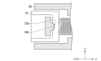
- Pin clamp 40 is omitted in Figures 9 to 12. It should be noted that pin clamp 40 may be omitted. 9, the ferrule side contact surface 14b is a flat surface, and the housing side contact surface 22a is a curved surface. In this case, the ferrule 10 can also swing relative to the housing 20. In other words, if one of the ferrule side contact surface 14b and the housing side contact surface 22a is a curved surface, the ferrule 10 can swing.
- a recess recessed toward the tip side (+Z side) is formed in the first restricting portion 22.
- the inside of this recess serves as a housing side contact surface 22a.
- a recess recessed toward the base end side ( ⁇ Z side) is formed in the ferrule 10.
- the inside of this recess serves as the ferrule side contact surface 14b.
- a protrusion 14P is formed on the ferrule 10.
- the protrusion 14P protrudes outward in the orthogonal direction Y from the first end face 14 of the ferrule 10.
- the outer circumferential surface of this protrusion 14P serves as the ferrule side contact surface 14b.
- Figures 9 to 12 show the structure on the first end face 14 side of the ferrule 10.
- a similar structure may also be provided on the second end face 15 side.
- the ferrule 10 in the example of Figure 12 may have, in addition to the protrusion 14P, a second protrusion that protrudes outward from the second end face 15 in the perpendicular direction Y.
- the outer peripheral surface of the second protrusion may be the ferrule side contact surface.
- the ferrule 10 may have two protrusions, and the outer peripheral surfaces of the two protrusions may each be the ferrule side contact surface.
Landscapes
- Physics & Mathematics (AREA)
- General Physics & Mathematics (AREA)
- Optics & Photonics (AREA)
- Mechanical Coupling Of Light Guides (AREA)
Priority Applications (2)
| Application Number | Priority Date | Filing Date | Title |
|---|---|---|---|
| JP2025532635A JPWO2025013575A1 (https=) | 2023-07-12 | 2024-06-21 | |
| CN202480043428.6A CN121532683A (zh) | 2023-07-12 | 2024-06-21 | 光连接器以及插芯 |
Applications Claiming Priority (2)
| Application Number | Priority Date | Filing Date | Title |
|---|---|---|---|
| JP2023114788 | 2023-07-12 | ||
| JP2023-114788 | 2023-07-12 |
Publications (1)
| Publication Number | Publication Date |
|---|---|
| WO2025013575A1 true WO2025013575A1 (ja) | 2025-01-16 |
Family
ID=94215674
Family Applications (1)
| Application Number | Title | Priority Date | Filing Date |
|---|---|---|---|
| PCT/JP2024/022610 Pending WO2025013575A1 (ja) | 2023-07-12 | 2024-06-21 | 光コネクタおよびフェルール |
Country Status (3)
| Country | Link |
|---|---|
| JP (1) | JPWO2025013575A1 (https=) |
| CN (1) | CN121532683A (https=) |
| WO (1) | WO2025013575A1 (https=) |
Cited By (1)
| Publication number | Priority date | Publication date | Assignee | Title |
|---|---|---|---|---|
| JP7669088B1 (ja) * | 2025-02-12 | 2025-04-28 | 株式会社狭山金型製作所 | フェルール |
Citations (8)
| Publication number | Priority date | Publication date | Assignee | Title |
|---|---|---|---|---|
| US6085003A (en) * | 1998-07-28 | 2000-07-04 | Us Conec Ltd | Multifiber connector having a free floating ferrule |
| US20050069264A1 (en) * | 2003-09-30 | 2005-03-31 | Luther James P. | Fiber optic connection for applying axial biasing force to multifiber ferrule |
| US20080089651A1 (en) * | 2006-10-11 | 2008-04-17 | Christopher Paul Lewallen | Connector assembly having multi-fiber ferrule with force centering |
| JP2008516274A (ja) * | 2004-10-11 | 2008-05-15 | エフシーアイ | 光ファイバ用コネクタ |
| US20080205823A1 (en) * | 2007-02-27 | 2008-08-28 | James Phillip Luther | Articulated force application for multi-fiber ferrules |
| WO2018180898A1 (ja) * | 2017-03-31 | 2018-10-04 | 古河電気工業株式会社 | 光コネクタプラグおよび光コネクタプラグ接続構造 |
| JP2019101232A (ja) | 2017-12-01 | 2019-06-24 | 株式会社フジクラ | 光コネクタ及び光コネクタの接続方法 |
| JP2023114788A (ja) | 2022-02-07 | 2023-08-18 | 日本薬品開発株式会社 | 小麦若葉搾汁乾燥粉末の青汁用飲食品組成物及び該飲食品組成物の嗜好性を高める方法 |
-
2024
- 2024-06-21 JP JP2025532635A patent/JPWO2025013575A1/ja active Pending
- 2024-06-21 CN CN202480043428.6A patent/CN121532683A/zh active Pending
- 2024-06-21 WO PCT/JP2024/022610 patent/WO2025013575A1/ja active Pending
Patent Citations (8)
| Publication number | Priority date | Publication date | Assignee | Title |
|---|---|---|---|---|
| US6085003A (en) * | 1998-07-28 | 2000-07-04 | Us Conec Ltd | Multifiber connector having a free floating ferrule |
| US20050069264A1 (en) * | 2003-09-30 | 2005-03-31 | Luther James P. | Fiber optic connection for applying axial biasing force to multifiber ferrule |
| JP2008516274A (ja) * | 2004-10-11 | 2008-05-15 | エフシーアイ | 光ファイバ用コネクタ |
| US20080089651A1 (en) * | 2006-10-11 | 2008-04-17 | Christopher Paul Lewallen | Connector assembly having multi-fiber ferrule with force centering |
| US20080205823A1 (en) * | 2007-02-27 | 2008-08-28 | James Phillip Luther | Articulated force application for multi-fiber ferrules |
| WO2018180898A1 (ja) * | 2017-03-31 | 2018-10-04 | 古河電気工業株式会社 | 光コネクタプラグおよび光コネクタプラグ接続構造 |
| JP2019101232A (ja) | 2017-12-01 | 2019-06-24 | 株式会社フジクラ | 光コネクタ及び光コネクタの接続方法 |
| JP2023114788A (ja) | 2022-02-07 | 2023-08-18 | 日本薬品開発株式会社 | 小麦若葉搾汁乾燥粉末の青汁用飲食品組成物及び該飲食品組成物の嗜好性を高める方法 |
Cited By (2)
| Publication number | Priority date | Publication date | Assignee | Title |
|---|---|---|---|---|
| JP7669088B1 (ja) * | 2025-02-12 | 2025-04-28 | 株式会社狭山金型製作所 | フェルール |
| JP7710781B1 (ja) * | 2025-02-12 | 2025-07-22 | 株式会社狭山金型製作所 | フェルール |
Also Published As
| Publication number | Publication date |
|---|---|
| JPWO2025013575A1 (https=) | 2025-01-16 |
| CN121532683A (zh) | 2026-02-13 |
Similar Documents
| Publication | Publication Date | Title |
|---|---|---|
| TWI608262B (zh) | 光纖連接器 | |
| CA2613658C (en) | Optical connector excellent in maintenance of a connected state | |
| CN102483496B (zh) | 改进对准的光纤适配器 | |
| JP4248401B2 (ja) | 浮遊型コネクタ副組み立て体とそれを含むコネクタ | |
| EP0938006B1 (en) | Structures for optical semiconductor module, optical connector, and shape adapting optical connector | |
| CN108072937B (zh) | 光学连接器 | |
| WO2025013575A1 (ja) | 光コネクタおよびフェルール | |
| WO1994015232A1 (en) | Opctical connector | |
| JPH11237527A (ja) | 光コネクタ | |
| US9989708B1 (en) | Connector with lateral and angular tolerance | |
| US7241057B2 (en) | Optical connector apparatus having a light shielding device of a simple structure | |
| WO2024247936A1 (ja) | 多心光コネクタ | |
| WO2022113435A1 (ja) | フェルール及び光コネクタ | |
| WO2024142472A1 (ja) | 光ファイバ保持部品およびフェルールアセンブリ | |
| JP2025024807A (ja) | 電気コネクタ | |
| WO2025263273A1 (ja) | 光コネクタ | |
| JP3815739B2 (ja) | レセプタクル型分割式光コネクタ | |
| WO2025154432A1 (ja) | 光コネクタ | |
| WO2023053754A1 (ja) | 光接続部品 | |
| WO2026009529A1 (ja) | 光コネクタ | |
| WO2025263321A1 (ja) | 光コネクタ | |
| WO2026009531A1 (ja) | 光コネクタ | |
| JP3721509B2 (ja) | 光コネクタ | |
| JP7673891B2 (ja) | 光アダプタおよび光コネクタユニット | |
| US6712521B1 (en) | Optical connector enabling multicore structure by efficiently utilizing space |
Legal Events
| Date | Code | Title | Description |
|---|---|---|---|
| 121 | Ep: the epo has been informed by wipo that ep was designated in this application |
Ref document number: 24839471 Country of ref document: EP Kind code of ref document: A1 |
|
| ENP | Entry into the national phase |
Ref document number: 2025532635 Country of ref document: JP Kind code of ref document: A |
|
| WWE | Wipo information: entry into national phase |
Ref document number: 2025532635 Country of ref document: JP |
|
| WWE | Wipo information: entry into national phase |
Ref document number: 2024839471 Country of ref document: EP |
|
| NENP | Non-entry into the national phase |
Ref country code: DE |