WO2025013447A1 - 溶融金属めっき鋼帯のスプラッシュ欠陥予測方法、溶融金属めっき鋼帯の製造方法、溶融金属めっき鋼帯のスプラッシュ欠陥予測装置および溶融金属めっき鋼帯製造設備 - Google Patents
溶融金属めっき鋼帯のスプラッシュ欠陥予測方法、溶融金属めっき鋼帯の製造方法、溶融金属めっき鋼帯のスプラッシュ欠陥予測装置および溶融金属めっき鋼帯製造設備 Download PDFInfo
- Publication number
- WO2025013447A1 WO2025013447A1 PCT/JP2024/019523 JP2024019523W WO2025013447A1 WO 2025013447 A1 WO2025013447 A1 WO 2025013447A1 JP 2024019523 W JP2024019523 W JP 2024019523W WO 2025013447 A1 WO2025013447 A1 WO 2025013447A1
- Authority
- WO
- WIPO (PCT)
- Prior art keywords
- steel strip
- hot
- dip metal
- gas
- spectral intensity
- Prior art date
- Legal status (The legal status is an assumption and is not a legal conclusion. Google has not performed a legal analysis and makes no representation as to the accuracy of the status listed.)
- Ceased
Links
Images





Classifications
-
- C—CHEMISTRY; METALLURGY
- C23—COATING METALLIC MATERIAL; COATING MATERIAL WITH METALLIC MATERIAL; CHEMICAL SURFACE TREATMENT; DIFFUSION TREATMENT OF METALLIC MATERIAL; COATING BY VACUUM EVAPORATION, BY SPUTTERING, BY ION IMPLANTATION OR BY CHEMICAL VAPOUR DEPOSITION, IN GENERAL; INHIBITING CORROSION OF METALLIC MATERIAL OR INCRUSTATION IN GENERAL
- C23C—COATING METALLIC MATERIAL; COATING MATERIAL WITH METALLIC MATERIAL; SURFACE TREATMENT OF METALLIC MATERIAL BY DIFFUSION INTO THE SURFACE, BY CHEMICAL CONVERSION OR SUBSTITUTION; COATING BY VACUUM EVAPORATION, BY SPUTTERING, BY ION IMPLANTATION OR BY CHEMICAL VAPOUR DEPOSITION, IN GENERAL
- C23C2/00—Hot-dipping or immersion processes for applying the coating material in the molten state without affecting the shape; Apparatus therefor
- C23C2/14—Removing excess of molten coatings; Controlling or regulating the coating thickness
- C23C2/16—Removing excess of molten coatings; Controlling or regulating the coating thickness using fluids under pressure, e.g. air knives
- C23C2/18—Removing excess of molten coatings from elongated material
- C23C2/20—Strips; Plates
-
- C—CHEMISTRY; METALLURGY
- C23—COATING METALLIC MATERIAL; COATING MATERIAL WITH METALLIC MATERIAL; CHEMICAL SURFACE TREATMENT; DIFFUSION TREATMENT OF METALLIC MATERIAL; COATING BY VACUUM EVAPORATION, BY SPUTTERING, BY ION IMPLANTATION OR BY CHEMICAL VAPOUR DEPOSITION, IN GENERAL; INHIBITING CORROSION OF METALLIC MATERIAL OR INCRUSTATION IN GENERAL
- C23C—COATING METALLIC MATERIAL; COATING MATERIAL WITH METALLIC MATERIAL; SURFACE TREATMENT OF METALLIC MATERIAL BY DIFFUSION INTO THE SURFACE, BY CHEMICAL CONVERSION OR SUBSTITUTION; COATING BY VACUUM EVAPORATION, BY SPUTTERING, BY ION IMPLANTATION OR BY CHEMICAL VAPOUR DEPOSITION, IN GENERAL
- C23C2/00—Hot-dipping or immersion processes for applying the coating material in the molten state without affecting the shape; Apparatus therefor
- C23C2/34—Hot-dipping or immersion processes for applying the coating material in the molten state without affecting the shape; Apparatus therefor characterised by the shape of the material to be treated
- C23C2/36—Elongated material
- C23C2/40—Plates; Strips
Definitions
- the present invention relates to a method for manufacturing a hot-dip metal-plated steel strip in which gas is blown from a gas wiping nozzle onto the surface of a steel strip that is continuously pulled up from a hot-dip metal plating bath, thereby controlling the amount of plating applied to the steel strip surface.
- Hot-dip metal-plated steel sheets are widely used in the fields of building materials, automobiles, home appliances, etc. Furthermore, for these applications, hot-dip galvanized steel sheets are required to have excellent appearance. Here, since the appearance after painting is strongly affected by surface defects such as uneven plating thickness, scratches, and foreign matter adhesion, it is important that hot-dip galvanized steel sheets are free of surface defects.
- a hot-dip metal-coated steel strip is generally manufactured in a continuous hot-dip metal coating line as shown in FIG. 1. That is, a steel strip S annealed in a continuous annealing furnace in a reducing atmosphere passes through a snout 2 and is continuously introduced into a molten metal bath 4 in a coating tank 3. The steel strip S is then pulled up above the molten metal bath 4 through a sink roll 5 and a support roll 6 in the molten metal bath 4, and after being adjusted to a predetermined coating thickness by a pair of gas wiping nozzles 10, it is cooled and introduced to a subsequent process.
- the pair of gas wiping nozzles 10 are disposed above the coating tank 3, facing each other across the steel strip S, and the gas injection port is composed of a slit 11 extending in the sheet width direction of the steel strip S.
- the gas wiping nozzle 10 is usually configured to be longer than the steel strip width and extends to the outside beyond the width end of the steel strip S in order to accommodate various steel strip widths and to accommodate widthwise deviations during steel strip pulling.
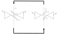
- the gas jets discharged from the gas wiping nozzles arranged on both sides of the steel strip remain as single jets and become wall jets after colliding with the steel strip, whereas at the edge of the steel strip, the gas jets from the opposing gas wiping nozzles collide with each other as shown in FIG. 2 and vibrate greatly up and down (for example, S. J. Kim, J, W. Cho, K, J. Ahn and M. K. Chung: ISIJ Int., 43 (2003)).
- the gas velocity fluctuation becomes very large at the edge of the steel strip, making splashes more likely to occur.
- the steel strip threading speed can be increased.
- the gas G sprayed onto the steel strip surface from the gas wiping nozzle 10 (10a, 10b) must be set at a higher pressure, which significantly increases splashes caused by collisions between jets at the edge of the steel strip, making it impossible to maintain good surface quality.
- Patent Document 1 places baffle plates on both sides of the steel strip that passes through it, and provides an inclined guide at the bottom corner of the baffle plate facing the steel strip, which redirects the flow of injected gas near the edge of the steel strip inward.
- Patent Document 2 involves providing a sub-nozzle (auxiliary nozzle) adjacent to the main nozzle (wiping nozzle), making the nozzle tip of the partition plate between the main nozzle and sub-nozzle at an acute angle, and slightly tilting the sub-jet from the sub-nozzle relative to the main jet from the main nozzle. According to the document, this lengthens the potential core, improving control over the amount of deposition and stabilizing the gas jet, thereby reducing noise.
- Patent Document 3 proposes the following method. This method utilizes the correlation between the frequency spectrum of the sound waves generated in the gas wiping section and the occurrence of splashes, measures the sound waves generated in the gas wiping section and converts them into a frequency spectrum, and adjusts the position of the gas wiping nozzle so that the sound pressure intensity or the integrated value of the sound pressure intensity in a specific frequency range of this frequency spectrum is equal to or less than a reference value.
- Patent Document 4 proposes a technique for adjusting the setting conditions of the gas wiping nozzle by utilizing the correlation between the frequency spectrum of the sound waves generated in the gas wiping section and the occurrence of splashes, so that a peak in the frequency spectrum does not appear in a specific frequency range.
- JP 2003-321756 A Japanese Patent Application Publication No. 10-204599 JP 2007-308778 A JP 2011-32526 A
- the "specific frequency range" to be evaluated spans a wide frequency range, and it is not possible to respond to slight changes in the gas vibration frequency spectrum related to splash generation. This means that it is not possible to properly detect changes in the splash generation situation due to changes in steel strip size or various other operational conditions, which can result in unstable operation.
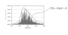
- Patent Document 4 calculates the frequency band in which the spectrum peak should be suppressed based on the gas pressure and the distance between the nozzles, but there is a problem in that the frequency band to be suppressed is almost constant for lines where the standard for the amount of adhesion is almost constant, making it impractical. In addition, there are cases where a broad peak appears as shown in Figure 3, and in such cases, changing the nozzle angle or nozzle height does not reduce the peak of the frequency band to be suppressed.
- the object of the present invention is to solve the problems of the conventional technology as described above, and to provide a method for predicting splash defects in hot-dip metal-plated steel strip in a hot-dip metal-plated steel strip manufacturing method in which a gas wiping nozzle is used to control the coating weight. It is also an object of the present invention to provide a hot-dip metal-plated steel strip manufacturing method using the hot-dip metal-plated steel strip splash defect prediction method, a hot-dip metal-plated steel strip splash defect prediction device, and hot-dip metal-plated steel strip manufacturing equipment including the hot-dip metal-plated steel strip splash defect prediction device.
- a method for predicting splash defects of a hot-dip metal-coated steel strip in a hot-dip metal-coated steel strip manufacturing facility in which a coating weight is controlled by spraying gas from a pair of opposed gas wiping nozzles onto both sides of a surface of the steel strip being continuously pulled up from a hot-dip metal coating bath comprising: a reference frequency band setting step of setting a reference frequency band HB including a frequency that is a peak in the power spectrum of sound waves generated in the gas wiping section when gas is sprayed onto the steel strip from one side of the gas wiping nozzle; A power spectrum determination step of determining a power spectrum of a sound wave generated at a gas wiping portion when gas is sprayed from the pair of gas wiping nozzles onto both sides of the steel strip during production of the hot-dip metal plated steel strip; a spectral intensity specifying step of specifying, from the power spectrum specified in the power spectrum specifying step,
- a method for predicting splash defects in hot-dip metal coated steel strip [2] A method for predicting splash defects in hot-dip metal-plated steel strips as described in [1], wherein the peak is the maximum value of the power spectrum of sound waves generated in the gas wiping section when gas is sprayed onto the steel strip from one side of the gas wiping nozzle. [3]
- the spectral intensity P B specified in the spectral intensity specifying step is a maximum spectral intensity in the reference frequency band H B
- the spectral intensity P A is a maximum spectral intensity in a frequency band lower than the reference frequency band H B .
- the reference frequency band HB is set from a peak of a spectrum intensity at a frequency of 2000 Hz or more and less than 3000 Hz
- the maximum spectral intensity PA specified in the spectral intensity specifying step is the maximum spectral intensity in a frequency band of 1000 Hz or more and less than 2000 Hz.
- the operating conditions of the hot-dip metal plating equipment are at least one selected from a nozzle angle, which is an angle between a horizontal plane and the direction of the gas sprayed from the gas nozzle of the gas wiping nozzle; a nozzle height, which is a distance from a liquid level of the hot-dip metal plating bath to the nozzle port of the gas wiping nozzle; an internal pressure of a nozzle header of the gas wiping nozzle; a nozzle-steel-plate distance, which is a distance between a tip of the gas nozzle and the steel strip; and a threading speed at which the steel strip is threaded.
- the method for producing a hot-dip metal-plated steel strip according to [5].
- a splash defect prediction device for a hot-dip metal-coated steel strip in a hot-dip metal-coated steel strip manufacturing facility in which a coating weight is controlled by spraying gas from a pair of opposed gas wiping nozzles onto both sides of a surface of the steel strip being continuously pulled up from a hot-dip metal coating bath comprising: a power spectrum acquisition unit that acquires a power spectrum of a sound wave generated in a gas wiping portion of the gas wiping nozzle; a reference frequency band setting unit that sets a reference frequency band HB including a frequency that is a peak in the power spectrum of sound waves generated in the gas wiping unit when gas is sprayed onto the steel strip from one side of the gas wiping nozzle; a spectral intensity specifying unit that specifies a spectral intensity PB in the reference frequency band HB and a spectral intensity PA appearing in a frequency band different from the reference frequency band HB from a power spectrum obtained when gas is sprayed from the pair of gas wiping nozzles onto both sides of
- a device for predicting splash defects in hot-dip galvanized steel strips [8] A splash defect prediction device for hot-dip metal-plated steel strip described in [7], wherein the peak in the reference frequency band setting unit is the maximum value of the power spectrum of the sound wave generated in the gas wiping unit when gas is sprayed onto the steel strip from one side of the gas wiping nozzle. [9]
- the spectral intensity P B specified by the spectral intensity specifying unit is a maximum spectral intensity in a reference frequency band H B
- the spectral intensity P A is a maximum spectral intensity in a frequency band lower than the reference frequency band H B .
- the splash defect prediction device for a hot-dip metal-plated steel strip according to [7] or [8].
- a hot-dip metal-plated steel strip manufacturing facility comprising the hot-dip metal-plated steel strip splash defect prediction device according to any one of [7] to [9].
- the present invention can provide a method for predicting splash defects in hot-dip metal plated steel strip caused by gas wiping, which is a source of splash generation. Furthermore, it can provide a method for manufacturing hot-dip metal plated steel strip using the method for predicting splash defects in hot-dip metal plated steel strip, a device for predicting splash defects in hot-dip metal plated steel strip, and hot-dip metal plated steel strip manufacturing equipment including a device for predicting splash defects in hot-dip metal plated steel strip.
- FIG. 1 is a diagram showing an example of continuous hot-dip metal plating equipment.
- FIG. 2 is a diagram showing a state in which gas jets from opposing gas wiping nozzles collide with each other.
- FIG. 1 is a diagram showing that there is a broad peak in the relationship between frequency and power spectrum.
- FIG. 2 is a diagram showing a configuration of a gas wiping nozzle.
- 1 is a schematic diagram of a splash defect detection device in a hot-dip galvanizing line.
- FIG. 2 is a diagram showing the positional relationship between a pair of gas wiping nozzles and a steel strip.
- FIG. 1 is a diagram showing an example of continuous hot-dip metal plating equipment.
- FIG. 2 is a diagram showing a state in which gas jets from opposing gas wiping nozzles collide with each other.
- FIG. 1 is a diagram showing that there is a broad peak in the relationship between frequency and power spectrum.
- FIG. 2 is a diagram showing a configuration of
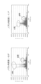
- FIG. 13 is a diagram showing the results of frequency analysis of the sound waves of the gas wiping vibration sound when the gas injection angle in the vertical direction of the gas wiping nozzle is changed under specified conditions, and converting them into a frequency spectrum.
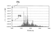
- FIG. 2 is a diagram showing the relationship between frequencies and the spectra of each frequency.
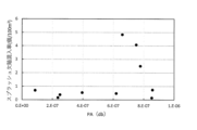
- FIG. 13 is a diagram showing the relationship between PA and splash defect contamination rate.
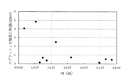
- FIG. 13 is a diagram showing the relationship between PB and the splash defect contamination rate.
- FIG. 13 is a graph showing the relationship between PA/PB and the splash defect contamination rate.
- FIG. 2 is a top view of the facility layout of the present invention.
- FIG. 2 is a data processing block diagram.
- FIG. 13 is a graph showing the change in splash defect rate over 10 days for an example of the present invention and a conventional example.
- the present invention is a method for predicting splash defects in hot-dip metal-plated steel strips in a manufacturing facility for hot-dip metal-plated steel strips, in which gas is sprayed from a pair of opposing gas wiping nozzles onto both sides of the surface of the steel strip as it is continuously pulled up from a hot-dip metal plating bath, thereby controlling the coating weight.
- gas is sprayed from a pair of opposing gas wiping nozzles onto both sides of the surface of the steel strip as it is continuously pulled up from a hot-dip metal plating bath, thereby controlling the coating weight.
- the continuous hot-dip metal plating equipment 1 shown in Figure 1 is equipment for continuously depositing molten metal onto the surface of a steel strip S by immersing the steel strip S in a molten metal bath 4 made of molten metal, and then depositing a predetermined amount of molten metal onto the surface of the steel strip S.
- the continuous hot-dip metal plating equipment 1 is equipped with a snout 2, a plating tank 3, a sink roll 5, and a support roll 6.
- wiping gas is sprayed from a pair of gas wiping nozzles 10a, 10b arranged on both sides of the steel strip S to adjust the amount of molten metal attached to both sides of the steel strip S.
- the steel strip S is then cooled by cooling equipment (not shown) and introduced to a subsequent process, where the hot-dip metal-plated steel strip S is continuously manufactured.
- a pair of gas wiping nozzles 10 arranged on both sides of the steel strip S includes a nozzle header 12, a first nozzle member 13 arranged on the upper side connected to the nozzle header 15, and a second nozzle member 14 arranged on the lower side, as shown in Figure 4.
- the first nozzle member 13 and the second nozzle member 14 are arranged opposite each other, and a slit 11 serving as a gas injection port is formed to extend elongatedly in the longitudinal direction X.
- the width of the mouth of the slit 11 (nozzle outlet) is called the slit gap 16.
- the nozzle height refers to the distance from the liquid surface of the molten metal plating bath to the nozzle opening of the gas wiping nozzle.
- the gas wiping nozzles 10a and 10b are arranged on each side of the steel strip S such that the length direction X of the slit 11 is aligned with the width direction of the steel strip S, the width direction Z perpendicular to the length direction X of the slit 11 is aligned with the length direction (passing direction) of the steel strip S, and the depth direction Y perpendicular to the length direction X of the slit 11 is aligned with the thickness direction of the steel strip S.
- the width direction Z of the slit is the same direction as the up-down direction of the gas wiping nozzles 10a and 10b.
- the wiping gas is sprayed from the slit 11 from one of the gas wiping nozzles 10a and 10b toward one side of the steel strip S.
- the wiping gas is sprayed from the slit 11 from the other gas wiping nozzle 10 toward the other side of the steel strip S.
- the gas wiping nozzles 10a and 10b are configured to be longer than the width of the steel strip S so that the length of the slit 11 is longer than the width of the steel strip S in order to accommodate various widths of the steel strip S and to accommodate positional deviations in the width direction when the steel strip S is pulled up, and extend to the outside from the end of the width direction of the steel strip S.
- the length of the slit 11 compared to the width of the steel strip S is not particularly limited, but the length of the slit 11 minus the width of the steel strip S is preferably 50 mm or more, more preferably 100 mm or more, and even more preferably 200 mm or more.
- the upper limit is not particularly limited, but the length of the slit 11 minus the width of the steel strip S is preferably 1500 mm or less, more preferably 1200 mm or less, and even more preferably 1000 mm or less.
- the plating weight was measured by fluorescent X-ray analysis (manufactured by Rigaku).
- the gas wiping nozzle shape was a slit gap of 1.0 mm, a nozzle distance of 14-20 mm, and a slit width of 1700 mm.
- Zinc was used for plating, the plating bath temperature was 460°C, and a steel strip with a thickness of 0.6-1.2 mm and a width of 900-1500 mm was passed through at 1.6-2.0 m/s.
- the nozzle gas pressure was adjusted in the range of 55-65 kPa so that the deposition amount was 45-50 g/ m2 .
- the above gas wiping nozzle shape is one example, and is not particularly limited to the above, but it is preferable to set it within the following range.
- the slit gap is preferably 0.5 mm or more, more preferably 0.8 mm or more, and even more preferably 1 mm or more.
- the slit gap is preferably 5 mm or less, and more preferably 3 mm or less.
- the nozzle distance is preferably 4 mm or more.
- the nozzle distance is preferably 20 mm or less, more preferably 15 mm or less, and even more preferably 10 mm or less.
- the bath temperature can be 440°C or higher. It is also preferable that the bath temperature be 470°C or lower.
- the plate thickness there are no particular limitations on the plate thickness, but it is preferable that the plate thickness be 0.6 mm or more. Also, it is preferable that the plate thickness be 3.2 mm or less. There are no particular limitations on the plate width, but it is preferable that the plate width be 700 mm or more. Also, it is preferable that the plate width be 1800 mm or less.
- the nozzle gas pressure is preferably 2 kPa or more, more preferably 20 kPa or more, and even more preferably 40 kPa or more.
- the nozzle gas pressure is preferably 100 kPa or less, more preferably 90 kPa or less, and even more preferably 80 kPa or less.
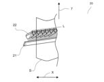
- the defect detection device 20 includes a floodlight 21 and a camera 22.
- the floodlight 21 is a device that irradiates the steel sheet surface with white light or monochromatic light at a certain angle with respect to the traveling direction of the hot-dip galvanized steel strip S. It is preferable that the floodlight 21 irradiates parallel light with respect to the steel sheet surface.
- a plurality of cameras 22 are arranged in the width direction of the hot-dip galvanized steel strip S so as to obtain images from a predetermined angle with respect to the traveling direction 7 of the hot-dip galvanized steel strip S.
- the number of cameras 22 is not particularly limited, but is preferably 20 or more. It is more preferable to have 30 or more, and even more preferable to have 40 or more. There is no particular upper limit, but it is preferably 60 or less, and more preferably 50 or less.
- the experimental results when the gas injection angle in the vertical direction of the gas wiping nozzle was changed at a gas pressure of 60 kPa, nozzle distance of 20 mm, plate thickness of 0.6 mm, and plate width of 1000 mm are shown below.
- the experiment was performed with an angle difference ⁇ ( ⁇ a- ⁇ b) of -0.8° and -1.1° in the gas injection angle in the vertical direction of a pair of gas wiping nozzles 10a and 10b.
- the angle difference ⁇ is preferably 0.1° or more, more preferably 0.2° or more, and even more preferably 0.3° or more.
- the angle difference ⁇ is preferably 5° or less, more preferably 3° or less, and even more preferably 2° or less.
- the reference frequency band HB When setting the reference frequency band HB, it is necessary to set it to a frequency band that includes a frequency that becomes a peak in the power spectrum of the sound waves generated in the gas wiping section when gas is sprayed onto the steel strip from one side of the gas wiping nozzle. At that time, it is preferable that the maximum spectral intensity is included in the power spectrum of the sound waves generated in the gas wiping section.
- the value of the B band peak remains roughly the same regardless of the nozzle angle, but the A band peak value differs greatly. It is presumed that the difference in nozzle angle changes the degree of collision of the opposing jets, causing the peak values to differ greatly.
- a frequency analysis was carried out on the sound waves measured when gas was discharged from only one gas wiping nozzle (either 10a or 10b) (when no opposing jet was generated) for the gas discharge sound from the gas wiping nozzle, a spectrum peak was found in the vicinity of 2000 to 2200 Hz, and this was determined to be the peak caused by the gas discharge sound from the gas wiping nozzle, i.e., the B band peak.
- the splash defect mixing rate which is the number of splash defects per unit area, was used as an index of the extent to which splash defects exist.
- the slit gap 16 was 0.8 to 1.5 mm
- the gas pressure was 50 to 70 kPa
- the nozzle parallel length was 20 to 30 mm
- the spectral intensity PA of the peak appearing due to the interference of the opposing jets was between 800 and 2500 Hz
- the spectral intensity PB of the peak appearing due to the gas discharge sound was between 1500 and 3500 Hz.
- the results cannot be organized by only the peak PA caused by the interference of the opposing jets or the peak PB caused by the gas discharge sound, that is, there is a large amount of variation and the tendency is not clear.
- the results can be stratified by calculating PB and PA and taking the ratio PA/PB.
- the pressure inside the nozzle header of a gas wiping nozzle (hereinafter also referred to as gas pressure) is the gas pressure measured in the nozzle header.
- the nozzle header is a space in front of the nozzle where gas is stored in order to discharge the gas uniformly in the width direction.
- This step corresponds to a reference frequency band setting step including a frequency that is a peak in the power spectrum of the sound waves generated in the gas wiping section when gas is sprayed from one side of the gas wiping nozzle onto the steel strip.
- the peak caused by the opposing jets is identified by ejecting gas from both of the opposing gas wiping nozzles 10 within the range of gas pressure expected during operation, and collecting sound at that time.
- This step corresponds to a power spectrum identification step of identifying the power spectrum of the sound waves generated in the gas wiping section when gas is sprayed from the pair of gas wiping nozzles 10 onto both sides of the steel strip during the production of a hot-dip metal plated steel strip.
- examples of the gas wiping conditions that can be changed include a nozzle angle, a nozzle height, a line speed, a gas pressure, and a nozzle distance.
- the threshold value of PA/PB is appropriately set based on the splash defect control range required for each line.
- the PA/PB value varies depending on the manufacturing conditions, and is not particularly limited, but may be, for example, 3 or less.
- PA/PB is a value greater than 0 (greater than 0).
- the spectral intensity identification step of identifying the spectral intensity PB in the reference frequency band HB and the spectral intensity PA appearing in a frequency band different from the reference frequency band HB it is preferable to identify the maximum spectral intensity PB and the maximum spectral intensity PA in both cases, but the above can be carried out even if neither is a maximum value.
- such analysis of the frequency spectrum of the sound waves from the gas wiping section and adjustment of the position of the gas wiping nozzle based on this analysis may be performed continuously during operation or at appropriate time intervals. It may also be performed as appropriate when changing plating conditions.
- the operating conditions of the hot-dip metal plating equipment are at least one selected from the nozzle angle, which is the angle between the horizontal plane and the direction of the gas sprayed from the gas nozzle of the gas wiping nozzle; the nozzle height, which is the distance from the liquid surface of the hot-dip metal plating bath to the nozzle nozzle of the gas wiping nozzle; the pressure inside the nozzle header of the gas wiping nozzle; the nozzle steel plate distance, which is the distance between the tip of the gas nozzle and the steel strip; and the threading speed at which the steel strip is threaded.
- the manufacturing method of the hot-dip metal plated steel strip of the present invention is a method of predicting the occurrence of splash defects in the hot-dip metal plated steel strip using the above-described method for predicting splash defects in the hot-dip metal plated steel strip, and of manufacturing the hot-dip metal plated steel strip by setting the operating conditions of the hot-dip metal plating equipment so as to suppress the occurrence of splash defects.
- the present invention also provides a splash defect prediction device for a hot-dip metal-plated steel strip, which is used in a hot-dip metal-plated steel strip manufacturing facility for controlling a coating weight of a hot-dip metal-plated steel strip by spraying gas from a pair of opposing gas wiping nozzles onto both sides of the surface of the steel strip being continuously pulled up from a hot-dip metal plating bath, and which comprises: a power spectrum acquisition unit that acquires a power spectrum of a sound wave generated in a gas wiping portion of the gas wiping nozzle; a reference frequency band setting unit that sets a reference frequency band HB including a peak of a spectrum intensity from a power spectrum acquired when a gas is ejected from one of the gas wiping nozzles; a spectral intensity specifying unit that specifies a spectral intensity PB in the reference frequency band HB and a spectral intensity PA appearing in a frequency band different from the reference frequency band HB from a power spectrum obtained when gas is sprayed from the pair of gas wi
- the hot-dip metal-plated steel strip manufacturing equipment of the present invention also includes the above-mentioned hot-dip metal-plated steel strip splash defect prediction device.
- a steel strip S having a thickness of 0.6 mm and a width of 900 to 1500 mm was threaded at a one-side coating weight of 45 to 50 g/ m2 and a threading speed of 1.67 to 2.0 m/sec to produce a hot-dip galvanized steel strip.
- the gas wiping nozzle 10 used had a slit width of 2000 mm, a slit gap of 1 mm, a nozzle gas pressure of 55-70 kPa, a nozzle-to-steel sheet distance of 7-10 mm, and a nozzle height from the plating bath surface of 200-700 mm.
- a microphone was installed 5 m away from the side of the gas wiping nozzle to measure the sound waves from the gas wiping section, and the sound waves were converted into a frequency spectrum by frequency analysis every 50 seconds using a sound wave analyzer (sampling frequency 50 kHz, sampling time 2 seconds).
- PA/PB was calculated from the maximum value PA in frequency band A: 1000-2000 Hz and the maximum value PB in frequency band B: 2000-3000 Hz, and the operating conditions were changed so that this value was below the threshold value.
Landscapes
- Chemical & Material Sciences (AREA)
- Chemical Kinetics & Catalysis (AREA)
- Engineering & Computer Science (AREA)
- Materials Engineering (AREA)
- Mechanical Engineering (AREA)
- Metallurgy (AREA)
- Organic Chemistry (AREA)
- Coating With Molten Metal (AREA)
Abstract
Description
このようなガスワイピングノズル10において、ガス噴射によって飛散した溶融金属の液滴P(以下、「スプラッシュ」と称する。)が鋼帯表面に付着してめっき鋼帯の表面品質の低下を招くという問題がある。溶融金属のスプラッシュの多くは、鋼帯エッジ部から発生する(エッジスプラッシュ)。これは以下のような理由による。鋼帯両側に配置されたガスワイピングノズルから吐出されたガス噴流は、鋼帯センター部では、鋼帯に衝突した後は単独噴流のまま壁面噴流となるのに対し、鋼帯エッジ部では、図2に示すように対向する両ガスワイピングノズルからのガス噴流が互いに衝突し、上下に大きく振動する(例えば、S.J.Kim、J、W.Cho、K、J.Ahn and M.K.Chung:ISIJ Int.、43(2003))。このため鋼帯エッジ部ではガスの速度変動(乱れ)が非常に大きくなり、スプラッシュが発生しやすくなる。鋼帯の連続処理プロセスにおいて生産量を増加させるには、鋼帯通板速度を増加させればよい。しかし、連続溶融めっきプロセスにおいてワイピング方式でめっき付着量を制御する場合、鋼帯通板速度を増加させると、溶融金属の粘性によって鋼帯Sのめっき浴通過直後の初期付着量が増加するため、めっき付着量を一定範囲内に制御するには、ガスワイピングノズル10(10a、10b)から鋼帯面に吹き付けるガスGをより高圧に設定する必要があり、これによって鋼帯エッジ部での噴流同士の衝突によるスプラッシュが大幅に増加し、良好な表面品質を維持できなくなる。
[1] 溶融金属めっき浴から連続的に引き上げられる鋼帯の表面に、対向する1対のガスワイピングノズルから前記鋼帯の両面にガスを吹き付けてめっき付着量の制御を行う溶融金属めっき鋼帯の製造設備における溶融金属めっき鋼帯のスプラッシュ欠陥予測方法であって、
前記ガスワイピングノズルの片側から前記鋼帯にガスを噴射した場合に、ガスワイピング部で発生する音波のパワースペクトルにおけるピークとなる周波数を含む基準周波数帯HBを設定する基準周波数帯設定ステップと、
溶融金属めっき鋼帯を製造する際に、前記1対のガスワイピングノズルから前記鋼帯の両面にガスを吹き付けるときにガスワイピング部で発生する音波のパワースペクトルを特定するパワースペクトル特定ステップと、
前記パワースペクトル特定ステップで特定したパワースペクトルから、前記基準周波数帯HBにおけるスペクトル強度PBと、前記基準周波数帯HBとは異なり、前記1対のガスワイピングノズルから前記鋼帯の両面にガスを吹き付ける時に、鋼帯道外で発生する対向噴流の干渉に起因する周波数帯に現れるスペクトル強度PAとを特定するスペクトル強度特定ステップと、
前記スペクトル強度PBと前記スペクトル強度PAとを用いて、スプラッシュ欠陥の発生を予測する欠陥予測ステップと、を含む、
溶融金属めっき鋼帯のスプラッシュ欠陥予測方法。
[2] 前記ピークは、前記ガスワイピングノズルの片側から前記鋼帯にガスを噴射した場合に、前記ガスワイピング部で発生する音波のパワースペクトルの最大値である、[1]に記載の溶融金属めっき鋼帯のスプラッシュ欠陥予測方法。
[3] 前記スペクトル強度特定ステップで特定する、前記スペクトル強度PBは前記基準周波数帯HBにおいて最大のスペクトル強度であり、かつ前記スペクトル強度PAは、前記基準周波数帯HBよりも低い周波数帯における最大のスペクトル強度である、
[1]または[2]に記載の溶融金属めっき鋼帯のスプラッシュ欠陥予測方法。
[4] 前記基準周波数帯HBは、前記基準周波数帯設定ステップにおいて、周波数2000Hz以上3000Hz未満におけるスペクトル強度のピークから設定し、
前記スペクトル強度特定ステップで特定する最大スペクトル強度PAは、周波数1000Hz以上2000Hz未満の周波数帯における最大のスペクトル強度である、
[1]~[3]のいずれかに記載の溶融金属めっき鋼帯のスプラッシュ欠陥予測方法。
[5] [1]~[4]のいずれかに記載の溶融金属めっき鋼帯のスプラッシュ欠陥予測方法を用いて、溶融金属めっき鋼帯のスプラッシュ欠陥の発生を予測し、スプラッシュ欠陥の発生を抑制するように、前記溶融金属めっき設備の操業条件を設定し、溶融金属めっき鋼帯を製造する、
溶融金属めっき鋼帯の製造方法。
[6] 前記溶融金属めっき設備の操業条件は、前記ガスワイピングノズルのガス噴射口から噴射する前記ガスの噴射方向と水平面とのなす角度であるノズル角度、前記溶融金属めっき浴の液面から前記ガスワイピングノズルのノズル口までの距離であるノズル高さ、前記ガスワイピングノズルのノズルヘッダの内部の圧力、前記ガス噴射口の先端と前記鋼帯との間隔であるノズル鋼板距離、および前記鋼帯が通板される通板速度、から選択した少なくとも一つである、
[5]に記載の溶融金属めっき鋼帯の製造方法。
[7] 溶融金属めっき浴から連続的に引き上げられる鋼帯の表面に、対向する1対のガスワイピングノズルから前記鋼帯の両面にガスを吹き付けてめっき付着量の制御を行う溶融金属めっき鋼帯の製造設備における溶融金属めっき鋼帯のスプラッシュ欠陥予測装置であって、
前記ガスワイピングノズルのガスワイピング部で発生する音波のパワースペクトルを取得するパワースペクトル取得部と、
前記ガスワイピングノズルの片側から前記鋼帯にガスを噴射した場合に、ガスワイピング部で発生する音波のパワースペクトルにおけるピークとなる周波数を含む基準周波数帯HBを設定する基準周波数帯設定部と、
溶融金属めっき鋼帯の製造工程において、前記1対のガスワイピングノズルから前記鋼帯の両面にガスを吹き付ける際に取得されるパワースペクトルから、前記基準周波数帯HBにおけるスペクトル強度PBと、前記基準周波数帯HBとは異なる周波数帯に現れるスペクトル強度PAを特定するスペクトル強度特定部と、
前記スペクトル強度PBと前記スペクトル強度PAとを用いて、スプラッシュ欠陥の発生を予測する欠陥予測部と、を含む、
溶融金属めっき鋼帯のスプラッシュ欠陥予測装置。
[8] 前記基準周波数帯設定部における前記ピークは、前記ガスワイピングノズルの片側から前記鋼帯にガスを噴射した場合に、ガスワイピング部で発生する音波のパワースペクトルの最大値である、[7]に記載の溶融金属めっき鋼帯のスプラッシュ欠陥予測装置。
[9] 前記スペクトル強度特定部で特定する、前記スペクトル強度PBは基準周波数帯HBにおいて最大のスペクトル強度であり、かつ前記スペクトル強度PAは、前記基準周波数帯HBよりも低い周波数帯における最大のスペクトル強度である、
[7]または[8]に記載の溶融金属めっき鋼帯のスプラッシュ欠陥予測装置。
[10] [7]~[9]のいずれかに記載の溶融金属めっき鋼帯のスプラッシュ欠陥予測装置を含む、溶融金属めっき鋼帯製造設備。
なお、上記めっき付着量は、蛍光X線分析(Rigaku製)にて測定して得られた結果である。
ガスワイピングノズルのノズルヘッダの内部の圧力(以降、ガス圧ともいう)とはノズルヘッダで測定されるガス圧力である。ノズルヘッダとは幅方向で均一にガスを出すために、ノズルの前にガスを溜める空間である。
ガス圧が大きいほどワイピングで掻き落される亜鉛の量は多くなり、液滴として飛散する亜鉛の量も増える。ガス圧に依存して変化するのはPBであり、このパラメータは飛散するベースの亜鉛の量と相関があると考えられる。これに対し、ノズルエッジにおける噴流の干渉の程度を表すパラメータがPAである。スプラッシュ欠陥となるかは掻き落される亜鉛がどれだけあるか、という点とその亜鉛が、噴流の干渉によってノズル上方にどれだけ飛散するか、という点で決まると考えられる。このため、単にそれぞれのパラメータのみでは欠陥の発生は説明できず、比を取ることによって初めて整理が可能になったと考えられる。
この工程が前記ガスワイピングノズルの片側から前記鋼帯にガスを噴射した場合に、ガスワイピング部で発生する音波のパワースペクトルにおけるピークとなる周波数を含む基準周波数帯設定ステップに相当する。S2にて、対向噴流に起因するピークは、対向するガスワイピングノズル10の両方から、操業中に想定されるガス圧の範囲でガスを吐出し、その際に集音を行ってピークの周波数帯を同定する。この工程が、溶融金属めっき鋼帯を製造する際に、前記1対のガスワイピングノズル10から前記鋼帯の両面にガスを吹き付けるときにガスワイピング部で発生する音波のパワースペクトルを特定するパワースペクトル特定ステップに相当する。S3にて、プロセス制御装置ではPA/PBを算出し、設定した閾値以上であれば、ガスワイピングの操業条件を変更し、PA/PBが閾値以下となるように調整する。この工程が、パワースペクトル特定ステップで特定したパワースペクトルから、前記基準周波数帯HBにおけるスペクトル強度PBと、前記基準周波数帯HBとは異なる周波数帯に現れるスペクトル強度PAを特定するスペクトル強度特定ステップと、前記スペクトル強度PBと前記スペクトル強度PAとを用いて、スプラッシュ欠陥の発生を予測する欠陥予測ステップに相当する。なお、変更可能なガスワイピング条件としては、ノズル角度、ノズル高さ、ライン速度、ガス圧、ノズル間距離が挙げられる。
PA/PBの閾値は各ラインで必要とされるスプラッシュ欠陥の管理範囲に基づいて適宜設定する。PA/PB値は製造条件によって変化しており、特に限定されるものではないが、例えば3以下であってよい。また、PA/PBは0より大きい値(0超え)となる。
前記ガスワイピングノズルのガスワイピング部で発生する音波のパワースペクトルを取得するパワースペクトル取得部と、
予め、前記ガスワイピングノズルの一方からガスを噴射した際に取得されるパワースペクトルからスペクトル強度のピークを含む基準周波数帯HBを設定する基準周波数帯設定部と、
溶融金属めっき鋼帯の製造工程において、前記1対のガスワイピングノズルから前記鋼帯の両面にガスを吹き付ける際に取得されるパワースペクトルから、前記基準周波数帯HBにおけるスペクトル強度PBと、前記基準周波数帯HBとは異なる周波数帯に現れるスペクトル強度PAを特定するスペクトル強度特定部と、
前記スペクトル強度PBと前記スペクトル強度PAとを用いて、スプラッシュ欠陥の発生を予測する欠陥予測部と、を含むものである。
基準周波数帯設定部では、前記ガスワイピングノズルから前記鋼帯にガスを噴射した際にガスワイピング部で発生する音波のパワースペクトルからスペクトル強度が最大である周波数を含む基準周波数帯HBに設定することが好ましい。また、前記基準周波数帯HBにおけるスペクトル強度PBと、前記基準周波数帯HBとは異なる周波数帯に現れるスペクトル強度PAを特定するスペクトル強度特定部では、いずれも最大スペクトル強度PBと最大スペクトル強度PAとを特定することが好ましいが、いずれも最大値でなくても上記は実施できる。
2 スナウト
3 めっき槽
4 溶融金属浴
5 シンクロール
6 サポートロール
7 鋼帯Sの進行方向
10、10a、10b ガスワイピングノズル
11 スリット
12 ノズルヘッダ
13 第1のノズル部材
14 第2のノズル部材
15 ノズルヘッダ
16 スリットギャップ
20 欠陥検出装置
21 投光器
22 カメラ
30 音圧検出用マイク(集音マイク)
31 音波解析装置(周波数解析装置)
32 ガスワイピングノズル
S 鋼帯
P 溶融金属の溶滴(スプラッシュ)
L 検査線
G ガス
X 長さ方向
Y 奥行方向
Z 幅方向
PA 対向噴流の干渉に起因して現れるピークのスペクトル強度
PB ガスの吐出音に起因して現れるピークのスペクトル強度
Claims (10)
- 溶融金属めっき浴から連続的に引き上げられる鋼帯の表面に、対向する1対のガスワイピングノズルから前記鋼帯の両面にガスを吹き付けてめっき付着量の制御を行う溶融金属めっき鋼帯の製造設備における溶融金属めっき鋼帯のスプラッシュ欠陥予測方法であって、
前記ガスワイピングノズルの片側から前記鋼帯にガスを噴射した場合に、ガスワイピング部で発生する音波のパワースペクトルにおけるピークとなる周波数を含む基準周波数帯HBを設定する基準周波数帯設定ステップと、
溶融金属めっき鋼帯を製造する際に、前記1対のガスワイピングノズルから前記鋼帯の両面にガスを吹き付けるときにガスワイピング部で発生する音波のパワースペクトルを特定するパワースペクトル特定ステップと、
前記パワースペクトル特定ステップで特定したパワースペクトルから、前記基準周波数帯HBにおけるスペクトル強度PBと、前記基準周波数帯HBとは異なり、前記1対のガスワイピングノズルから前記鋼帯の両面にガスを吹き付ける時に、鋼帯道外で発生する対向噴流の干渉に起因する周波数帯に現れるスペクトル強度PAとを特定するスペクトル強度特定ステップと、
前記スペクトル強度PBと前記スペクトル強度PAとを用いて、スプラッシュ欠陥の発生を予測する欠陥予測ステップと、を含む、
溶融金属めっき鋼帯のスプラッシュ欠陥予測方法。 - 前記ピークは、前記ガスワイピングノズルの片側から前記鋼帯にガスを噴射した場合に、前記ガスワイピング部で発生する音波のパワースペクトルの最大値である、請求項1に記載の溶融金属めっき鋼帯のスプラッシュ欠陥予測方法。
- 前記スペクトル強度特定ステップで特定する、前記スペクトル強度PBは前記基準周波数帯HBにおいて最大のスペクトル強度であり、かつ前記スペクトル強度PAは、前記基準周波数帯HBよりも低い周波数帯における最大のスペクトル強度である、
請求項1または2に記載の溶融金属めっき鋼帯のスプラッシュ欠陥予測方法。 - 前記基準周波数帯HBは、前記基準周波数帯設定ステップにおいて、周波数2000Hz以上3000Hz未満におけるスペクトル強度のピークから設定し、
前記スペクトル強度特定ステップで特定する最大スペクトル強度PAは、周波数1000Hz以上2000Hz未満の周波数帯における最大のスペクトル強度である、
請求項1~3のいずれかに記載の溶融金属めっき鋼帯のスプラッシュ欠陥予測方法。 - 請求項1~4のいずれかに記載の溶融金属めっき鋼帯のスプラッシュ欠陥予測方法を用いて、溶融金属めっき鋼帯のスプラッシュ欠陥の発生を予測し、スプラッシュ欠陥の発生を抑制するように、前記溶融金属めっき設備の操業条件を設定し、溶融金属めっき鋼帯を製造する、
溶融金属めっき鋼帯の製造方法。 - 前記溶融金属めっき設備の操業条件は、前記ガスワイピングノズルのガス噴射口から噴射する前記ガスの噴射方向と水平面とのなす角度であるノズル角度、前記溶融金属めっき浴の液面から前記ガスワイピングノズルのノズル口までの距離であるノズル高さ、前記ガスワイピングノズルのノズルヘッダの内部の圧力、前記ガス噴射口の先端と前記鋼帯との間隔であるノズル鋼板距離、および前記鋼帯が通板される通板速度、から選択した少なくとも一つである、
請求項5に記載の溶融金属めっき鋼帯の製造方法。 - 溶融金属めっき浴から連続的に引き上げられる鋼帯の表面に、対向する1対のガスワイピングノズルから前記鋼帯の両面にガスを吹き付けてめっき付着量の制御を行う溶融金属めっき鋼帯の製造設備における溶融金属めっき鋼帯のスプラッシュ欠陥予測装置であって、
前記ガスワイピングノズルのガスワイピング部で発生する音波のパワースペクトルを取得するパワースペクトル取得部と、
前記ガスワイピングノズルの片側から前記鋼帯にガスを噴射した場合に、ガスワイピング部で発生する音波のパワースペクトルにおけるピークとなる周波数を含む基準周波数帯HBを設定する基準周波数帯設定部と、
溶融金属めっき鋼帯の製造工程において、前記1対のガスワイピングノズルから前記鋼帯の両面にガスを吹き付ける際に取得されるパワースペクトルから、前記基準周波数帯HBにおけるスペクトル強度PBと、前記基準周波数帯HBとは異なる周波数帯に現れるスペクトル強度PAを特定するスペクトル強度特定部と、
前記スペクトル強度PBと前記スペクトル強度PAとを用いて、スプラッシュ欠陥の発生を予測する欠陥予測部と、を含む、
溶融金属めっき鋼帯のスプラッシュ欠陥予測装置。 - 前記基準周波数帯設定部における前記ピークは、前記ガスワイピングノズルの片側から前記鋼帯にガスを噴射した場合に、ガスワイピング部で発生する音波のパワースペクトルの最大値である、請求項7に記載の溶融金属めっき鋼帯のスプラッシュ欠陥予測装置。
- 前記スペクトル強度特定部で特定する、前記スペクトル強度PBは基準周波数帯HBにおいて最大のスペクトル強度であり、かつ前記スペクトル強度PAは、前記基準周波数帯HBよりも低い周波数帯における最大のスペクトル強度である、
請求項7または8に記載の溶融金属めっき鋼帯のスプラッシュ欠陥予測装置。 - 請求項7~9のいずれかに記載の溶融金属めっき鋼帯のスプラッシュ欠陥予測装置を含む、溶融金属めっき鋼帯製造設備。
Priority Applications (2)
| Application Number | Priority Date | Filing Date | Title |
|---|---|---|---|
| CN202480044948.9A CN121443766A (zh) | 2023-07-13 | 2024-05-28 | 熔融金属镀覆钢带的飞溅缺陷预测方法、熔融金属镀覆钢带的制造方法、熔融金属镀覆钢带的飞溅缺陷预测装置及熔融金属镀覆钢带制造设备 |
| MX2026000256A MX2026000256A (es) | 2023-07-13 | 2026-01-07 | Metodo para predecir defectos de salpicaduras en tiras de acero recubiertas de metal por inmersion en caliente, metodo para fabricar tiras de acero recubiertas de metal por inmersion en caliente, dispositivo para predecir defectos de salpicaduras en tiras de acero recubiertas de metal por inmersion en caliente, e instalacion de fabricacion de tiras de acero recubiertas de metal por inmersion en caliente |
Applications Claiming Priority (2)
| Application Number | Priority Date | Filing Date | Title |
|---|---|---|---|
| JP2023-114924 | 2023-07-13 | ||
| JP2023114924A JP7718453B2 (ja) | 2023-07-13 | 2023-07-13 | 溶融金属めっき鋼帯のスプラッシュ欠陥予測方法、溶融金属めっき鋼帯の製造方法、溶融金属めっき鋼帯のスプラッシュ欠陥予測装置および溶融金属めっき鋼帯製造設備 |
Publications (1)
| Publication Number | Publication Date |
|---|---|
| WO2025013447A1 true WO2025013447A1 (ja) | 2025-01-16 |
Family
ID=94215488
Family Applications (1)
| Application Number | Title | Priority Date | Filing Date |
|---|---|---|---|
| PCT/JP2024/019523 Ceased WO2025013447A1 (ja) | 2023-07-13 | 2024-05-28 | 溶融金属めっき鋼帯のスプラッシュ欠陥予測方法、溶融金属めっき鋼帯の製造方法、溶融金属めっき鋼帯のスプラッシュ欠陥予測装置および溶融金属めっき鋼帯製造設備 |
Country Status (4)
| Country | Link |
|---|---|
| JP (1) | JP7718453B2 (ja) |
| CN (1) | CN121443766A (ja) |
| MX (1) | MX2026000256A (ja) |
| WO (1) | WO2025013447A1 (ja) |
Citations (4)
| Publication number | Priority date | Publication date | Assignee | Title |
|---|---|---|---|---|
| JP2007308778A (ja) * | 2006-05-20 | 2007-11-29 | Jfe Steel Kk | 溶融金属めっき鋼帯の製造方法 |
| JP2011032526A (ja) * | 2009-07-31 | 2011-02-17 | Jfe Steel Corp | 溶融金属めっき鋼帯の製造方法 |
| JP2011102408A (ja) * | 2009-11-10 | 2011-05-26 | Jfe Steel Corp | 溶融金属めっき鋼帯の製造方法 |
| EP3825684A1 (fr) * | 2019-11-25 | 2021-05-26 | Primetals Technologies France SAS | Système d'essorage d'un revêtement de métal liquide sur une bande métallique en défilement |
-
2023
- 2023-07-13 JP JP2023114924A patent/JP7718453B2/ja active Active
-
2024
- 2024-05-28 WO PCT/JP2024/019523 patent/WO2025013447A1/ja not_active Ceased
- 2024-05-28 CN CN202480044948.9A patent/CN121443766A/zh active Pending
-
2026
- 2026-01-07 MX MX2026000256A patent/MX2026000256A/es unknown
Patent Citations (4)
| Publication number | Priority date | Publication date | Assignee | Title |
|---|---|---|---|---|
| JP2007308778A (ja) * | 2006-05-20 | 2007-11-29 | Jfe Steel Kk | 溶融金属めっき鋼帯の製造方法 |
| JP2011032526A (ja) * | 2009-07-31 | 2011-02-17 | Jfe Steel Corp | 溶融金属めっき鋼帯の製造方法 |
| JP2011102408A (ja) * | 2009-11-10 | 2011-05-26 | Jfe Steel Corp | 溶融金属めっき鋼帯の製造方法 |
| EP3825684A1 (fr) * | 2019-11-25 | 2021-05-26 | Primetals Technologies France SAS | Système d'essorage d'un revêtement de métal liquide sur une bande métallique en défilement |
Also Published As
| Publication number | Publication date |
|---|---|
| CN121443766A (zh) | 2026-01-30 |
| MX2026000256A (es) | 2026-03-02 |
| JP2025012224A (ja) | 2025-01-24 |
| JP7718453B2 (ja) | 2025-08-05 |
Similar Documents
| Publication | Publication Date | Title |
|---|---|---|
| CN114502764A (zh) | 用于制造具有改善外观的镀覆金属条带的设备和方法 | |
| EP1063314B1 (en) | Method of manufacturing hot dip coated metal strip | |
| JP7718453B2 (ja) | 溶融金属めっき鋼帯のスプラッシュ欠陥予測方法、溶融金属めっき鋼帯の製造方法、溶融金属めっき鋼帯のスプラッシュ欠陥予測装置および溶融金属めっき鋼帯製造設備 | |
| CN107532271B (zh) | 热镀金属钢带的制造装置和制造方法 | |
| KR102405526B1 (ko) | 용융 금속 도금 강대의 제조 방법 및 연속 용융 금속 도금 설비 | |
| JP4857906B2 (ja) | 溶融金属めっき鋼帯の製造方法 | |
| JP5532831B2 (ja) | 溶融金属めっき鋼帯の製造方法 | |
| JP6500846B2 (ja) | 溶融金属めっき鋼帯の製造方法及び連続溶融金属めっき設備 | |
| JP5640340B2 (ja) | 溶融金属めっき鋼帯の製造方法 | |
| JP2019167553A (ja) | 溶融金属めっき鋼帯の製造方法及び製造装置 | |
| US9708702B2 (en) | Wiping device and hot dip coating apparatus using the same | |
| KR20020047352A (ko) | 폭방향 에어압력편차를 제거한 에어 나이프 | |
| JPH042756A (ja) | 連続溶融めっきにおけるガスワイピング方法 | |
| US20240352569A1 (en) | Method for manufacturing hot-dip metal-coated steel strip | |
| JP5396996B2 (ja) | 溶融めっき鋼板の製造方法 | |
| JP6414360B2 (ja) | 溶融金属めっき鋼帯の製造方法 | |
| JP3814170B2 (ja) | 溶融メッキ鋼板の冷却方法及びその装置 | |
| JPH08127853A (ja) | 溶融金属鍍金方法 | |
| JPH0718398A (ja) | 鋼板の連続溶融めっき方法 | |
| JP5803754B2 (ja) | 溶融金属めっき鋼帯の製造方法 | |
| JP2009275242A (ja) | 溶融金属めっき鋼板の製造方法及び製造装置 | |
| ELLEN et al. | MOLTEN METALLIC COATINGS | |
| JPH042757A (ja) | 溶融金属めっきの差厚付着量制御装置及び方法 | |
| JPH0841617A (ja) | 溶融めっき鋼板の幅方向目付制御方法 | |
| Soufiani et al. | LES SIMULATION OF GAS JET WIPING VIA MULTI SLOT AIR KNIVES AND EXPERIMENTAL NOISE ATTENUATION MEASUREMENTS DURING CONTINUOUS HOT DIP GALVANIZING |
Legal Events
| Date | Code | Title | Description |
|---|---|---|---|
| 121 | Ep: the epo has been informed by wipo that ep was designated in this application |
Ref document number: 24839344 Country of ref document: EP Kind code of ref document: A1 |
|
| WWE | Wipo information: entry into national phase |
Ref document number: 202617001390 Country of ref document: IN |
|
| WWE | Wipo information: entry into national phase |
Ref document number: 2601000071 Country of ref document: TH Ref document number: MX/A/2026/000256 Country of ref document: MX |
|
| WWP | Wipo information: published in national office |
Ref document number: 202617001390 Country of ref document: IN |
|
| NENP | Non-entry into the national phase |
Ref country code: DE |
|
| WWP | Wipo information: published in national office |
Ref document number: MX/A/2026/000256 Country of ref document: MX |