WO2025013389A1 - 燃料供給システムおよび船舶 - Google Patents
燃料供給システムおよび船舶 Download PDFInfo
- Publication number
- WO2025013389A1 WO2025013389A1 PCT/JP2024/017084 JP2024017084W WO2025013389A1 WO 2025013389 A1 WO2025013389 A1 WO 2025013389A1 JP 2024017084 W JP2024017084 W JP 2024017084W WO 2025013389 A1 WO2025013389 A1 WO 2025013389A1
- Authority
- WO
- WIPO (PCT)
- Prior art keywords
- pump
- fuel supply
- tank
- pressure
- hydrogen
- Prior art date
- Legal status (The legal status is an assumption and is not a legal conclusion. Google has not performed a legal analysis and makes no representation as to the accuracy of the status listed.)
- Ceased
Links
Images

Classifications
-
- B—PERFORMING OPERATIONS; TRANSPORTING
- B63—SHIPS OR OTHER WATERBORNE VESSELS; RELATED EQUIPMENT
- B63B—SHIPS OR OTHER WATERBORNE VESSELS; EQUIPMENT FOR SHIPPING
- B63B11/00—Interior subdivision of hulls
- B63B11/04—Constructional features of bunkers, e.g. structural fuel tanks, or ballast tanks, e.g. with elastic walls
-
- B—PERFORMING OPERATIONS; TRANSPORTING
- B63—SHIPS OR OTHER WATERBORNE VESSELS; RELATED EQUIPMENT
- B63B—SHIPS OR OTHER WATERBORNE VESSELS; EQUIPMENT FOR SHIPPING
- B63B25/00—Load-accommodating arrangements, e.g. stowing, trimming; Vessels characterised thereby
- B63B25/02—Load-accommodating arrangements, e.g. stowing, trimming; Vessels characterised thereby for bulk goods
- B63B25/08—Load-accommodating arrangements, e.g. stowing, trimming; Vessels characterised thereby for bulk goods fluid
- B63B25/12—Load-accommodating arrangements, e.g. stowing, trimming; Vessels characterised thereby for bulk goods fluid closed
- B63B25/16—Load-accommodating arrangements, e.g. stowing, trimming; Vessels characterised thereby for bulk goods fluid closed heat-insulated
-
- B—PERFORMING OPERATIONS; TRANSPORTING
- B63—SHIPS OR OTHER WATERBORNE VESSELS; RELATED EQUIPMENT
- B63H—MARINE PROPULSION OR STEERING
- B63H21/00—Use of propulsion power plant or units on vessels
- B63H21/38—Apparatus or methods specially adapted for use on marine vessels, for handling power plant or unit liquids, e.g. lubricants, coolants, fuels or the like
-
- B—PERFORMING OPERATIONS; TRANSPORTING
- B63—SHIPS OR OTHER WATERBORNE VESSELS; RELATED EQUIPMENT
- B63J—AUXILIARIES ON VESSELS
- B63J2/00—Arrangements of ventilation, heating, cooling, or air-conditioning
- B63J2/12—Heating; Cooling
-
- F—MECHANICAL ENGINEERING; LIGHTING; HEATING; WEAPONS; BLASTING
- F02—COMBUSTION ENGINES; HOT-GAS OR COMBUSTION-PRODUCT ENGINE PLANTS
- F02M—SUPPLYING COMBUSTION ENGINES IN GENERAL WITH COMBUSTIBLE MIXTURES OR CONSTITUENTS THEREOF
- F02M21/00—Apparatus for supplying engines with non-liquid fuels, e.g. gaseous fuels stored in liquid form
- F02M21/02—Apparatus for supplying engines with non-liquid fuels, e.g. gaseous fuels stored in liquid form for gaseous fuels
- F02M21/0203—Apparatus for supplying engines with non-liquid fuels, e.g. gaseous fuels stored in liquid form for gaseous fuels characterised by the type of gaseous fuel
- F02M21/0206—Non-hydrocarbon fuels, e.g. hydrogen, ammonia or carbon monoxide
-
- F—MECHANICAL ENGINEERING; LIGHTING; HEATING; WEAPONS; BLASTING
- F17—STORING OR DISTRIBUTING GASES OR LIQUIDS
- F17C—VESSELS FOR CONTAINING OR STORING COMPRESSED, LIQUEFIED OR SOLIDIFIED GASES; FIXED-CAPACITY GAS-HOLDERS; FILLING VESSELS WITH, OR DISCHARGING FROM VESSELS, COMPRESSED, LIQUEFIED, OR SOLIDIFIED GASES
- F17C13/00—Details of vessels or of the filling or discharging of vessels
- F17C13/04—Arrangement or mounting of valves
-
- F—MECHANICAL ENGINEERING; LIGHTING; HEATING; WEAPONS; BLASTING
- F17—STORING OR DISTRIBUTING GASES OR LIQUIDS
- F17C—VESSELS FOR CONTAINING OR STORING COMPRESSED, LIQUEFIED OR SOLIDIFIED GASES; FIXED-CAPACITY GAS-HOLDERS; FILLING VESSELS WITH, OR DISCHARGING FROM VESSELS, COMPRESSED, LIQUEFIED, OR SOLIDIFIED GASES
- F17C9/00—Methods or apparatus for discharging liquefied or solidified gases from vessels not under pressure
-
- F—MECHANICAL ENGINEERING; LIGHTING; HEATING; WEAPONS; BLASTING
- F17—STORING OR DISTRIBUTING GASES OR LIQUIDS
- F17C—VESSELS FOR CONTAINING OR STORING COMPRESSED, LIQUEFIED OR SOLIDIFIED GASES; FIXED-CAPACITY GAS-HOLDERS; FILLING VESSELS WITH, OR DISCHARGING FROM VESSELS, COMPRESSED, LIQUEFIED, OR SOLIDIFIED GASES
- F17C2221/00—Handled fluid, in particular type of fluid
- F17C2221/01—Pure fluids
- F17C2221/012—Hydrogen
-
- F—MECHANICAL ENGINEERING; LIGHTING; HEATING; WEAPONS; BLASTING
- F17—STORING OR DISTRIBUTING GASES OR LIQUIDS
- F17C—VESSELS FOR CONTAINING OR STORING COMPRESSED, LIQUEFIED OR SOLIDIFIED GASES; FIXED-CAPACITY GAS-HOLDERS; FILLING VESSELS WITH, OR DISCHARGING FROM VESSELS, COMPRESSED, LIQUEFIED, OR SOLIDIFIED GASES
- F17C2227/00—Transfer of fluids, i.e. method or means for transferring the fluid; Heat exchange with the fluid
- F17C2227/03—Heat exchange with the fluid
- F17C2227/0337—Heat exchange with the fluid by cooling
- F17C2227/0339—Heat exchange with the fluid by cooling using the same fluid
-
- F—MECHANICAL ENGINEERING; LIGHTING; HEATING; WEAPONS; BLASTING
- F17—STORING OR DISTRIBUTING GASES OR LIQUIDS
- F17C—VESSELS FOR CONTAINING OR STORING COMPRESSED, LIQUEFIED OR SOLIDIFIED GASES; FIXED-CAPACITY GAS-HOLDERS; FILLING VESSELS WITH, OR DISCHARGING FROM VESSELS, COMPRESSED, LIQUEFIED, OR SOLIDIFIED GASES
- F17C2265/00—Effects achieved by gas storage or gas handling
- F17C2265/01—Purifying the fluid
- F17C2265/015—Purifying the fluid by separating
- F17C2265/017—Purifying the fluid by separating different phases of a same fluid
-
- F—MECHANICAL ENGINEERING; LIGHTING; HEATING; WEAPONS; BLASTING
- F17—STORING OR DISTRIBUTING GASES OR LIQUIDS
- F17C—VESSELS FOR CONTAINING OR STORING COMPRESSED, LIQUEFIED OR SOLIDIFIED GASES; FIXED-CAPACITY GAS-HOLDERS; FILLING VESSELS WITH, OR DISCHARGING FROM VESSELS, COMPRESSED, LIQUEFIED, OR SOLIDIFIED GASES
- F17C2265/00—Effects achieved by gas storage or gas handling
- F17C2265/03—Treating the boil-off
- F17C2265/032—Treating the boil-off by recovery
- F17C2265/033—Treating the boil-off by recovery with cooling
- F17C2265/034—Treating the boil-off by recovery with cooling with condensing the gas phase
-
- F—MECHANICAL ENGINEERING; LIGHTING; HEATING; WEAPONS; BLASTING
- F17—STORING OR DISTRIBUTING GASES OR LIQUIDS
- F17C—VESSELS FOR CONTAINING OR STORING COMPRESSED, LIQUEFIED OR SOLIDIFIED GASES; FIXED-CAPACITY GAS-HOLDERS; FILLING VESSELS WITH, OR DISCHARGING FROM VESSELS, COMPRESSED, LIQUEFIED, OR SOLIDIFIED GASES
- F17C2265/00—Effects achieved by gas storage or gas handling
- F17C2265/06—Fluid distribution
- F17C2265/066—Fluid distribution for feeding engines for propulsion
-
- F—MECHANICAL ENGINEERING; LIGHTING; HEATING; WEAPONS; BLASTING
- F17—STORING OR DISTRIBUTING GASES OR LIQUIDS
- F17C—VESSELS FOR CONTAINING OR STORING COMPRESSED, LIQUEFIED OR SOLIDIFIED GASES; FIXED-CAPACITY GAS-HOLDERS; FILLING VESSELS WITH, OR DISCHARGING FROM VESSELS, COMPRESSED, LIQUEFIED, OR SOLIDIFIED GASES
- F17C2270/00—Applications
- F17C2270/01—Applications for fluid transport or storage
- F17C2270/0102—Applications for fluid transport or storage on or in the water
- F17C2270/0105—Ships
-
- Y—GENERAL TAGGING OF NEW TECHNOLOGICAL DEVELOPMENTS; GENERAL TAGGING OF CROSS-SECTIONAL TECHNOLOGIES SPANNING OVER SEVERAL SECTIONS OF THE IPC; TECHNICAL SUBJECTS COVERED BY FORMER USPC CROSS-REFERENCE ART COLLECTIONS [XRACs] AND DIGESTS
- Y02—TECHNOLOGIES OR APPLICATIONS FOR MITIGATION OR ADAPTATION AGAINST CLIMATE CHANGE
- Y02T—CLIMATE CHANGE MITIGATION TECHNOLOGIES RELATED TO TRANSPORTATION
- Y02T10/00—Road transport of goods or passengers
- Y02T10/10—Internal combustion engine [ICE] based vehicles
- Y02T10/30—Use of alternative fuels, e.g. biofuels
-
- Y—GENERAL TAGGING OF NEW TECHNOLOGICAL DEVELOPMENTS; GENERAL TAGGING OF CROSS-SECTIONAL TECHNOLOGIES SPANNING OVER SEVERAL SECTIONS OF THE IPC; TECHNICAL SUBJECTS COVERED BY FORMER USPC CROSS-REFERENCE ART COLLECTIONS [XRACs] AND DIGESTS
- Y02—TECHNOLOGIES OR APPLICATIONS FOR MITIGATION OR ADAPTATION AGAINST CLIMATE CHANGE
- Y02T—CLIMATE CHANGE MITIGATION TECHNOLOGIES RELATED TO TRANSPORTATION
- Y02T70/00—Maritime or waterways transport
- Y02T70/50—Measures to reduce greenhouse gas emissions related to the propulsion system
Definitions
- the present disclosure relates to a fuel supply system for an internal combustion engine and a ship including the fuel supply system.
- Patent Document 1 discloses a fuel supply system for diesel engines. This fuel supply system forcibly vaporizes liquefied gas and supplies the vaporized gas to the diesel engine as fuel.
- liquefied gas is discharged from a tank through a fuel supply line.
- the fuel supply line is provided with a pump that pressurizes the liquefied gas so that the vaporized gas has a pressure higher than the pressure required by the diesel engine, and a carburetor is provided downstream of the pump.
- Patent Document 1 states that the liquefied gas may be liquefied hydrogen.
- the liquefied hydrogen reaches or exceeds its critical pressure when the pump increases the pressure of the liquefied hydrogen to a pressure higher than the pressure required by the diesel engine.
- the liquefied hydrogen also reaches or exceeds its critical pressure when the pump increases the pressure of the liquefied hydrogen to a pressure higher than the pressure required by the internal combustion engine.
- the pump discharges either liquefied hydrogen below the critical temperature, or supercritical hydrogen above the critical temperature.
- the vaporizer acts as a heater.
- the pump discharges liquefied hydrogen below the critical temperature, the liquid hydrogen becomes supercritical hydrogen when heated by the vaporizer.
- the present disclosure therefore aims to provide a fuel supply system that can re-liquefy hydrogen gas produced by reducing the pressure of liquefied hydrogen above its critical pressure and suck it into a pump.
- the present disclosure provides a fuel supply system for supplying supercritical hydrogen as fuel to an internal combustion engine, the fuel supply system comprising: a tank for storing liquefied hydrogen; a fuel supply line for discharging liquefied hydrogen from the tank; a first pump provided in the fuel supply line; a stirring device provided in the fuel supply line downstream of the first pump; a second pump provided in the fuel supply line downstream of the stirring device for pressurizing the liquefied hydrogen to a pressure equal to or higher than the critical pressure; and a reflux line provided with a pressure reducing valve that branches off from the fuel supply line downstream of the second pump and leads to the stirring device, the stirring device condensing the hydrogen gas by mixing hydrogen gas generated by pressure reduction using the pressure reducing valve with the liquefied hydrogen flowing through the fuel supply line.
- the present disclosure provides a ship equipped with the above-mentioned fuel supply system.
- a fuel supply system that can re-liquefy hydrogen gas generated by reducing the pressure of liquefied hydrogen above its critical pressure and suck it into a pump.
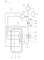
- FIG. 1 is a schematic diagram of a reliquefaction device according to an embodiment.
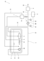
- FIG. 13 is a schematic diagram of a reliquefaction device according to a modified example.
- FIG. 13 is a schematic diagram of a reliquefaction device according to another modified example.
- FIG. 1 shows a fuel supply system 1A according to one embodiment.
- the fuel supply system 1A supplies supercritical hydrogen as fuel to an internal combustion engine.
- the fuel supply system 1A may be mounted on a ship or incorporated into a land-based power generation facility.
- the internal combustion engine is, for example, a reciprocating engine or a gas turbine engine.
- the reciprocating engine may be any of an Otto cycle, a Diesel cycle, and a Sabate cycle.
- the fuel supply system 1A includes a tank 2 that stores liquefied hydrogen and a fuel supply line 3 that outputs the liquefied hydrogen from the tank 2.
- a tank 2 that stores liquefied hydrogen
- a fuel supply line 3 that outputs the liquefied hydrogen from the tank 2.
- boil-off gas BOG is generated due to evaporation of the liquefied hydrogen.
- the tank 2 is a double-shelled tank including an inner tank 21 and an outer tank 22. A vacuum layer is formed between the inner tank 21 and the outer tank 22.
- the tank 2 may be a single-shelled tank covered with a heat insulating material.
- the tank 2 is a horizontal cylindrical shape.
- the tank 2 may also be a vertical cylindrical shape.
- the tank 2 may be a spherical shape or a roughly rectangular parallelepiped shape.
- a first pump 4A, an agitator 5, a second pump 4B, and a heater 6 are provided in that order from the upstream side.
- the first pump 4A is provided in the fuel supply line 3 downstream of the upstream end of the fuel supply line 3.
- the first pump 4A is disposed outside the tank 2 and within the vacuum insulation pod 11.
- the vacuum insulation pod 11 has a vacuum layer formed between the inner wall and the outer wall.
- the inner tank 21 of the tank 2 and the first pump 4A are connected by an outlet path 31.
- the outlet path 31 constitutes the upstream portion of the fuel supply line 3.
- the inside of the vacuum insulation pod 11 is filled with liquefied hydrogen or hydrogen gas.
- the portion of the outlet path 31 located inside the outer tank 22 of the tank 2 is composed of a single pipe, the portion between the outer tank 22 and the inner or outer wall of the vacuum insulation pod 11 is composed of a vacuum insulation double pipe, and the portion located inside the inner or outer wall of the vacuum insulation pod 11 is composed of a single pipe.
- the first pump 4A draws in liquefied hydrogen from the tank 2 through the discharge passage 31.
- the first pump 4A and the agitator 5 are connected by a first discharge passage 32, and the agitator 5 and the second pump 4B are connected by a suction passage 33.
- the second pump 4B and the heater 6 are connected by a second discharge passage 34, and a supply passage 35 extends from the heater 6.
- a shutoff valve is provided in the supply passage 35 to switch whether or not fuel is supplied to the internal combustion engine.
- the agitator 5 and the second pump 4B are disposed outside the tank 2, and the agitator 5 is disposed inside the vacuum insulation pod 12.
- the vacuum insulation pod 12 has a vacuum layer formed between its inner and outer walls.
- the inside of the vacuum insulation pod 12 is filled with liquefied hydrogen or hydrogen gas.
- the inside of the vacuum insulation pod 12 may be kept in a vacuum, in which case the vacuum insulation pod 12 may not have an inner wall.
- the surface of the agitator 5 may be covered with a vacuum insulation structure.
- the portion of the first discharge passage 32 located within the inner or outer wall of the vacuum insulation pod 11 is constructed with a single pipe
- the portion between the inner or outer wall of the vacuum insulation pod 11 and the inner or outer wall of the vacuum insulation pod 12 is constructed with a vacuum insulation double pipe
- the portion located within the inner or outer wall of the vacuum insulation pod 12 is constructed with a single pipe.
- the portion of the suction passage 33 located within the inner or outer wall of the vacuum insulation pod 12 is constructed with a single pipe
- the portion located outside the inner or outer wall of the vacuum insulation pod 12 is constructed with a vacuum insulation double pipe.
- the second discharge passage 34 may be constructed with either a single pipe or a vacuum insulation double pipe.
- the supply passage 35 is constructed with a single pipe. However, when the fuel supply system 1A is installed on a ship, the portion of the supply passage 35 located within the engine room may be constructed with a double pipe.
- the first pump 4A sends liquefied hydrogen from the tank 2 to the second pump 4B via the agitator 5.
- the second pump 4B pressurizes the liquefied hydrogen to a pressure higher than the pressure required by the internal combustion engine, to above the critical pressure.
- the outlet temperature of the second pump 4B is below the critical temperature, and liquefied hydrogen at or above the critical pressure is discharged from the second pump 4B.
- the internal combustion engine is a diesel cycle reciprocating engine
- the pressure of the liquefied hydrogen at the outlet of the second pump 4B is between 25 MPaG and 35 MPaG, and the temperature of the liquefied hydrogen at the outlet of the second pump 4B is 20K or higher.
- the heater 6 heats the liquefied hydrogen to a temperature higher than the required temperature of the internal combustion engine.
- the heating by the heater 6 turns the liquefied hydrogen into supercritical hydrogen.
- the temperature of the supercritical hydrogen at the outlet of the heater 6 is between 273K and 333K.
- the fuel supply system 1A includes a reflux line 7 that branches off from the fuel supply line 3 downstream of the second pump 4B and upstream of the heater 6, and connects to the agitator 5.
- the portion of the reflux line 7 located outside the inner or outer wall of the vacuum insulation pod 12 is made of a vacuum insulation double pipe, and the portion located inside the inner or outer wall of the vacuum insulation pod 12 is made of a single pipe.
- the reflux line 7 is provided with, in order from the upstream side, a pressure reducing valve 71 and a gas-liquid separator 72.
- Liquefied hydrogen above the critical pressure is reduced in pressure reducing valve 71 to become 100% hydrogen gas or a two-phase gas-liquid fluid.
- hydrogen gas and liquefied hydrogen are separated in gas-liquid separator 72 and flow out from gas-liquid separator 72.
- the gas-liquid separator 72 is connected to the tank 2 via a liquid supply line 73.
- the liquefied hydrogen separated in the gas-liquid separator 72 is returned to the tank 2 via the liquid supply line 73.
- the downstream portion of the liquid supply line 73 passes through the tank 2 from the outside to the inside.
- the downstream end of the liquid supply line 73 opens near the bottom of the inner tank 21 of the tank 2, but the downstream end of the liquid supply line 73 may be configured to be able to spray liquefied hydrogen above the liquid level in the tank 2.
- the portion of the liquid supply line 73 located outside the outer tank 22 of the tank 2 is made up of a vacuum insulated double pipe, and the portion located inside the outer tank 22 is made up of a single pipe.
- the agitator 5 condenses the hydrogen gas by mixing the hydrogen gas flowing out of the gas-liquid separator 72 with the liquefied hydrogen flowing through the fuel supply line 3. Note that instead of placing the agitator 5 inside the vacuum insulation pod 12, the surface of the agitator 5 may be covered with a vacuum insulation structure.
- a return line 8 branches off from the suction passage 33 of the fuel supply line 3, and the return line 8 is connected to the tank 2.
- the downstream portion of the return line 8 penetrates the tank 2 from the outside to the inside.
- the downstream end of the return line 8 opens near the bottom of the inner tank 21 of the tank 2, but the downstream end of the return line 8 may be configured to be able to spray liquefied hydrogen above the liquid level in the tank 2.
- the portion of the return line 8 located outside the outer tank 22 of the tank 2 is made up of a vacuum insulated double pipe, and the portion located inside the outer tank 22 is made up of a single pipe.
- the return line 8 is provided with a flow control valve 81.
- the flow control valve 81, as well as the first pump 4A, the second pump 4B, and the pressure reducing valve 71 described above, are controlled by a control device 9. Note that in FIG. 1, some signal lines are omitted from the drawing to simplify the drawing.
- circuits or processing circuits including general purpose processors, special purpose processors, integrated circuits, ASICs (Application Specific Integrated Circuits), conventional circuits, and/or combinations thereof, configured or programmed to perform the disclosed functions.
- a processor is considered a processing circuit or circuit because it includes transistors and other circuitry.
- a circuit, unit, or means is hardware that performs the recited functions or hardware that is programmed to perform the recited functions.
- the hardware may be hardware disclosed herein or other known hardware that is programmed or configured to perform the recited functions. Where the hardware is a processor, which is considered a type of circuit, the circuit, means, or unit is a combination of hardware and software, and the software is used to configure the hardware and/or the processor.
- the control device 9 is electrically connected to a pressure gauge 91 provided in the intake passage 33 of the fuel supply line 3 and a pressure gauge 92 provided in the second discharge passage 34.
- the pressure gauge 91 detects the pressure P1 of the liquefied hydrogen sucked into the second pump 4B.
- the pressure gauge 92 detects the pressure P2 of the liquefied hydrogen discharged from the second pump 4B, which is equal to or higher than the critical pressure.
- the pressure gauge 92 may also be provided in the supply passage 35 of the fuel supply line 3 to detect the pressure of the supercritical hydrogen flowing out from the heater 6.
- the control device 9 controls the rotation speed of the first pump 4A so that the pressure P1 detected by the pressure gauge 91 is equal to or greater than a predetermined value ⁇ , and controls the rotation speed of the second pump 4B so that the pressure P2 detected by the pressure gauge 92 is equal to or greater than a predetermined value ⁇ .
- the predetermined value ⁇ which is the target value for the inlet pressure of the second pump 4B, is a pressure (above the saturation pressure) at which the hydrogen gas sent from the reflux line 7 can be condensed.
- the control device 9 also controls the flow control valve 81 so that the discharge flow rate of the first pump 4A does not fall below a predetermined minimum flow rate. It is preferable that the flow control valve 81 is fully closed. However, if the discharge flow rate of the first pump 4A falls below the predetermined minimum flow rate when the flow control valve 81 is fully closed, the flow control valve 81 is opened, thereby connecting the suction passage 33 to the tank 2 via the return line 8, thereby controlling the discharge flow rate of the first pump 4A to be equal to or greater than the predetermined minimum flow rate.
- control device 9 controls the opening degree of the pressure reducing valve 71 based on the pressure P2 detected by the pressure gauge 92. More specifically, when the pressure P2 detected by the pressure gauge 92 is smaller than the threshold value ⁇ , the control device 9 fully closes the pressure reducing valve 71. On the other hand, when the pressure P2 detected by the pressure gauge 92 is greater than the threshold value ⁇ , the control device 9 opens the pressure reducing valve 71 to an opening degree according to the deviation ⁇ P between the pressure P2 and the threshold value ⁇ . As a result, the excess liquefied hydrogen above the critical pressure is reduced in pressure by the pressure reducing valve 71, generating hydrogen gas, which is then supplied to the agitation device 5 and condensed.
- the hydrogen gas generated by the pressure reduction valve 71 reducing the pressure of liquefied hydrogen above its critical pressure is condensed in the agitator 5 upstream of the second pump 4B. Therefore, the hydrogen gas generated by the pressure reduction of liquefied hydrogen above its critical pressure can be re-liquefied and sucked into the second pump 4B.
- the first pump 4A, the second pump 4B, and the agitator 5 are disposed outside the tank 2, so that the first pump 4A, the second pump 4B, and the agitator 5 can be easily maintained.
- the reflux line 7 may not be provided with a gas-liquid separator 72, and the liquid delivery line 73 may be omitted.
- the liquefied hydrogen separated by the gas-liquid separator 72 can be returned to the tank 2.
- the return line 8 may be omitted.
- the fuel supply system 1B may be modified so that the agitator 5 is disposed inside the tank 2 and the first pump 4A and the second pump 4B are disposed outside the tank 2. This configuration allows the fuel supply system 1B to be made compact.
- the first pump 4A and the agitator 5 may be disposed inside the tank 2, and the second pump 4B may be disposed outside the tank 2.
- the first pump 4A is provided in the fuel supply line 3 at the upstream end of the fuel supply line 3.
- the first discharge passage 32 of the fuel supply line 3 penetrates from the inside to the outside of the tank 2 and then from the outside to the inside, but the entire first discharge passage 32 may be disposed within the tank 2.
- the present disclosure provides a fuel supply system that supplies supercritical hydrogen as fuel to an internal combustion engine, the fuel supply system comprising: a tank that stores liquefied hydrogen; a fuel supply line that draws out liquefied hydrogen from the tank; a first pump provided in the fuel supply line; a stirring device provided in the fuel supply line downstream of the first pump; a second pump provided in the fuel supply line downstream of the stirring device that pressurizes the liquefied hydrogen to a pressure equal to or higher than its critical pressure; and a reflux line that branches off from the fuel supply line downstream of the second pump and leads to the stirring device, the reflux line being provided with a pressure reducing valve, and the stirring device condenses the hydrogen gas by mixing hydrogen gas generated by pressure reduction by the pressure reducing valve with the liquefied hydrogen flowing through the fuel supply line.
- the fuel supply system according to the first aspect may further include a gas-liquid separator provided in the reflux line downstream of the pressure reducing valve, and a liquid supply line connecting the gas-liquid separator to the tank.
- the first pump, the second pump, and the agitator may be disposed outside the tank. With this configuration, the first pump, the second pump, and the agitator can be easily maintained.
- the stirring device may be disposed inside the tank, and the first pump and the second pump may be disposed outside the tank.
- the fuel supply system can be made compact.
- the stirring device and the first pump may be disposed inside the tank, and the second pump may be disposed outside the tank.
- the present disclosure provides a ship including the fuel supply system according to any one of the first to fifth aspects.
Landscapes
- Engineering & Computer Science (AREA)
- Mechanical Engineering (AREA)
- Chemical & Material Sciences (AREA)
- Combustion & Propulsion (AREA)
- Ocean & Marine Engineering (AREA)
- General Engineering & Computer Science (AREA)
- Chemical Kinetics & Catalysis (AREA)
- General Chemical & Material Sciences (AREA)
- Oil, Petroleum & Natural Gas (AREA)
- Filling Or Discharging Of Gas Storage Vessels (AREA)
Abstract
Description
本開示は上述した実施形態に限定されるものではなく、本開示の要旨を逸脱しない範囲で種々の変形が可能である。
第1の態様として、本開示は、一つの側面から、超臨界水素を燃料として内燃機関へ供給する燃料供給システムであって、液化水素を貯留するタンクと、前記タンクから液化水素を導出する燃料供給ラインと、前記燃料供給ラインに設けられた第1ポンプと、前記第1ポンプよりも下流側で前記燃料供給ラインに設けられた撹拌装置と、前記撹拌装置よりも下流側で前記燃料供給ラインに設けられた、前記液化水素を昇圧して臨界圧力以上とする第2ポンプと、前記第2ポンプの下流側で前記燃料供給ラインから分岐して前記撹拌装置につながる、減圧弁が設けられた還流ラインと、を備え、前記撹拌装置は、前記減圧弁による減圧によって生じた水素ガスを前記燃料供給ラインを流れる液化水素と撹拌することで前記水素ガスを凝縮する、燃料供給システムを提供する。
Claims (6)
- 超臨界水素を燃料として内燃機関へ供給する燃料供給システムであって、
液化水素を貯留するタンクと、
前記タンクから液化水素を導出する燃料供給ラインと、
前記燃料供給ラインに設けられた第1ポンプと、
前記第1ポンプよりも下流側で前記燃料供給ラインに設けられた撹拌装置と、
前記撹拌装置よりも下流側で前記燃料供給ラインに設けられた、前記液化水素を昇圧して臨界圧力以上とする第2ポンプと、
前記第2ポンプの下流側で前記燃料供給ラインから分岐して前記撹拌装置につながる、減圧弁が設けられた還流ラインと、を備え、
前記撹拌装置は、前記減圧弁による減圧によって生じた水素ガスを前記燃料供給ラインを流れる液化水素と撹拌することで前記水素ガスを凝縮する、燃料供給システム。 - 前記減圧弁よりも下流側で前記還流ラインに設けられた気液分離器と、
前記気液分離器と前記タンクとを接続する送液ラインと、
をさらに備える、請求項1に記載の燃料供給システム。 - 前記第1ポンプ、前記第2ポンプおよび前記撹拌装置は前記タンク外に配置される、請求項1または2に記載の燃料供給システム。
- 前記撹拌装置は前記タンク内に配置され、前記第1ポンプおよび前記第2ポンプは前記タンク外に配置される、請求項1または2に記載の燃料供給システム。
- 前記撹拌装置および前記第1ポンプは前記タンク内に配置され、前記第2ポンプは前記タンク外に配置される、請求項1または2に記載の燃料供給システム。
- 請求項1または2に記載の燃料供給システムを備える船舶。
Priority Applications (2)
| Application Number | Priority Date | Filing Date | Title |
|---|---|---|---|
| KR1020267001437A KR20260025388A (ko) | 2023-07-07 | 2024-05-08 | 연료 공급 시스템 및 선박 |
| CN202480045715.0A CN121464274A (zh) | 2023-07-07 | 2024-05-08 | 燃料供给系统及船舶 |
Applications Claiming Priority (2)
| Application Number | Priority Date | Filing Date | Title |
|---|---|---|---|
| JP2023111940A JP2025009143A (ja) | 2023-07-07 | 2023-07-07 | 燃料供給システムおよび船舶 |
| JP2023-111940 | 2023-07-07 |
Publications (1)
| Publication Number | Publication Date |
|---|---|
| WO2025013389A1 true WO2025013389A1 (ja) | 2025-01-16 |
Family
ID=94215359
Family Applications (1)
| Application Number | Title | Priority Date | Filing Date |
|---|---|---|---|
| PCT/JP2024/017084 Ceased WO2025013389A1 (ja) | 2023-07-07 | 2024-05-08 | 燃料供給システムおよび船舶 |
Country Status (4)
| Country | Link |
|---|---|
| JP (1) | JP2025009143A (ja) |
| KR (1) | KR20260025388A (ja) |
| CN (1) | CN121464274A (ja) |
| WO (1) | WO2025013389A1 (ja) |
Citations (3)
| Publication number | Priority date | Publication date | Assignee | Title |
|---|---|---|---|---|
| JP2016049881A (ja) * | 2014-08-29 | 2016-04-11 | 川崎重工業株式会社 | 船舶 |
| KR20210118296A (ko) * | 2020-03-20 | 2021-09-30 | 삼성중공업 주식회사 | 선박 |
| JP2022511486A (ja) * | 2018-12-19 | 2022-01-31 | レール・リキード-ソシエテ・アノニム・プール・レテュード・エ・レクスプロワタシオン・デ・プロセデ・ジョルジュ・クロード | 液体水素を供給するためのポンピング装置、プラント、及び方法 |
-
2023
- 2023-07-07 JP JP2023111940A patent/JP2025009143A/ja active Pending
-
2024
- 2024-05-08 KR KR1020267001437A patent/KR20260025388A/ko active Pending
- 2024-05-08 WO PCT/JP2024/017084 patent/WO2025013389A1/ja not_active Ceased
- 2024-05-08 CN CN202480045715.0A patent/CN121464274A/zh active Pending
Patent Citations (3)
| Publication number | Priority date | Publication date | Assignee | Title |
|---|---|---|---|---|
| JP2016049881A (ja) * | 2014-08-29 | 2016-04-11 | 川崎重工業株式会社 | 船舶 |
| JP2022511486A (ja) * | 2018-12-19 | 2022-01-31 | レール・リキード-ソシエテ・アノニム・プール・レテュード・エ・レクスプロワタシオン・デ・プロセデ・ジョルジュ・クロード | 液体水素を供給するためのポンピング装置、プラント、及び方法 |
| KR20210118296A (ko) * | 2020-03-20 | 2021-09-30 | 삼성중공업 주식회사 | 선박 |
Also Published As
| Publication number | Publication date |
|---|---|
| CN121464274A (zh) | 2026-02-03 |
| KR20260025388A (ko) | 2026-02-24 |
| JP2025009143A (ja) | 2025-01-20 |
Similar Documents
| Publication | Publication Date | Title |
|---|---|---|
| US11441736B2 (en) | Multi-vessel fluid storage and delivery system | |
| AU2010318839B2 (en) | Fuel supply system and high-pressure pump for combustion engine | |
| CN104955727B (zh) | 天然气体燃料供给装置、船舶、向发动机供给天然气体燃料的方法 | |
| JP2004036608A (ja) | 液化ガス輸送船舶の発電システムへのガス状燃料供給設備 | |
| US6868839B2 (en) | Vaporized fuel injection system and method | |
| CA2517113C (en) | Lpg vehicular liquid transfer system | |
| JP2004076825A (ja) | 液化ガス処理装置 | |
| KR20110077332A (ko) | Lng 저장탱크의 증발가스 억제 방법 및 시스템 | |
| TW200946400A (en) | Device for supplying fuel to an energy producing installation of a ship | |
| JP6757217B2 (ja) | 船舶 | |
| JP2025009143A (ja) | 燃料供給システムおよび船舶 | |
| JP2001349256A (ja) | 内燃機関の燃料供給システム | |
| WO2025013388A1 (ja) | 燃料供給システムおよび船舶 | |
| CN111344481A (zh) | 用于以天然气运行内燃机的方法,用于能以天然运行的内燃机的燃料供给系统 | |
| JP2006257967A (ja) | 内燃機関の液化ガス燃料供給装置 | |
| CN111322176A (zh) | 一种可靠性高的船用lng供气输送系统 | |
| JP2001317426A (ja) | 燃料供給装置 | |
| JP7142125B1 (ja) | 液化ガス貯蔵設備及び船舶 | |
| CN109891147A (zh) | 液化气体再气化系统和其操作方法 | |
| JP2010144845A (ja) | 液化天然ガス車両の燃料系システム | |
| JPH0926097A (ja) | 低温液化ガス貯蔵設備 | |
| KR100967817B1 (ko) | 선박용 lng 재기화 시스템 | |
| JP2024134698A (ja) | 貯蔵システム | |
| JP2026032342A (ja) | 舶用燃料ガス供給システム及び液化ガス燃料船 | |
| JP2001342904A (ja) | エンジンの液化ガス供給装置 |
Legal Events
| Date | Code | Title | Description |
|---|---|---|---|
| 121 | Ep: the epo has been informed by wipo that ep was designated in this application |
Ref document number: 24839287 Country of ref document: EP Kind code of ref document: A1 |
|
| ENP | Entry into the national phase |
Ref document number: 1020267001437 Country of ref document: KR Free format text: ST27 STATUS EVENT CODE: A-0-1-A10-A15-NAP-PA0105 (AS PROVIDED BY THE NATIONAL OFFICE) |
|
| WWE | Wipo information: entry into national phase |
Ref document number: 1020267001437 Country of ref document: KR |
|
| NENP | Non-entry into the national phase |
Ref country code: DE |
|
| WWP | Wipo information: published in national office |
Ref document number: 1020267001437 Country of ref document: KR |
|
| 122 | Ep: pct application non-entry in european phase |
Ref document number: 24839287 Country of ref document: EP Kind code of ref document: A1 |