WO2025013294A1 - 教示システム、教示装置、ロボット制御装置、及びプログラム - Google Patents
教示システム、教示装置、ロボット制御装置、及びプログラム Download PDFInfo
- Publication number
- WO2025013294A1 WO2025013294A1 PCT/JP2023/025931 JP2023025931W WO2025013294A1 WO 2025013294 A1 WO2025013294 A1 WO 2025013294A1 JP 2023025931 W JP2023025931 W JP 2023025931W WO 2025013294 A1 WO2025013294 A1 WO 2025013294A1
- Authority
- WO
- WIPO (PCT)
- Prior art keywords
- image
- image data
- display
- teaching
- processor
- Prior art date
- Legal status (The legal status is an assumption and is not a legal conclusion. Google has not performed a legal analysis and makes no representation as to the accuracy of the status listed.)
- Pending
Links
Images


Classifications
-
- B—PERFORMING OPERATIONS; TRANSPORTING
- B25—HAND TOOLS; PORTABLE POWER-DRIVEN TOOLS; MANIPULATORS
- B25J—MANIPULATORS; CHAMBERS PROVIDED WITH MANIPULATION DEVICES
- B25J9/00—Program-controlled manipulators
- B25J9/10—Program-controlled manipulators characterised by positioning means for manipulator elements
Definitions
- This disclosure relates to a teaching system, a teaching device, a robot control device, and a program.
- the worker When performing calibration or position detection using a dot pattern or marker, the worker generally needs to take out the jig or printed material on which the dot pattern or marker is formed from its storage location to perform the work. There is a demand for technology that can reduce the burden on workers when performing calibration or position detection using a dot pattern or marker.
- One aspect of the present disclosure is a teaching system for teaching calibration or position detection, comprising a first device having a first processor and a storage unit that stores image data for the calibration or position detection, and a second device having a second processor and a display.
- the second processor acquires the image data from the first device, and displays an image represented by the image data on the display to be captured by a visual sensor in performing the calibration or position detection.
- FIG. 1 is a system configuration diagram of a teaching system for teaching regarding calibration or position detection according to a first embodiment.
- 1 is a functional block diagram of a teaching system according to a first embodiment.
- FIG. FIG. 4 is a diagram showing an overall flow of processing related to teaching a predetermined pattern in calibration or position detection in the first embodiment.
- 3B is a flowchart showing the process of the second device in step S1 of FIG. 3A.
- FIG. 13 is a diagram showing a state in which a dot pattern for calibration is displayed on the display of the teaching pendant.
- FIG. 13 is a diagram showing a state in which a dot pattern is displayed in an overlapping manner on an operation screen for teaching.
- FIG. 13 is a diagram showing an example of an image data registration screen displayed on a display of a teaching pendant.
- FIG. 11 is a diagram showing the configuration of a device in which a second device that downloads and displays image data of a predetermined pattern is a tablet terminal separate from the teaching pendant.
- FIG. 2 is a functional block diagram of the tablet terminal.
- FIG. 13 is a diagram showing a state in which a marker for position detection is displayed on the display of the tablet terminal.
- FIG. 13 is a diagram showing a state in which a marker for position detection is displayed on a display of a machine tool.
- FIG. 11 is a system configuration diagram of a teaching system for teaching regarding calibration or position detection according to a second embodiment.
- FIG. 11 is a functional block diagram of a teaching system according to a second embodiment.
- FIG. 13 is a diagram showing a state in which an image showing a dot pattern and a numerical value of a dot interval as dimensional information is displayed on the display of a teaching pendant.
- FIG. 13 is a diagram showing a state in which a code image is displayed as dimensional information together with a dot pattern on the display of a teaching pendant.
- FIG. 11 is a diagram showing an overall flow of processing related to teaching a predetermined pattern in calibration or position detection in the second embodiment.
- 14B is a flowchart showing the process performed by the second device in step S1a of FIG. 14A.
- FIG. 11 is a system configuration diagram of a teaching system for teaching regarding calibration or position detection according to a third embodiment.
- FIG. 13 is a functional block diagram of a teaching system according to a third embodiment.
- FIG. 13 is a diagram showing an overall flow of processing related to teaching a predetermined pattern in calibration or position detection in the third embodiment.
- 17B is a flowchart showing the process performed by the second device in step S1b of FIG. 17A.
- FIG. 13 is a diagram illustrating an example of an execution screen of a calibration program.
- the predetermined pattern for calibration may include various dot patterns and markers known in the art that can be used for calibration.
- the above-mentioned Patent Documents 1 and 2 describe examples of dot patterns and markers used for calibration.
- Calibration corresponds to obtaining calibration data (transformation matrix) that associates a position on a camera image with a position in three-dimensional space.
- the calibration data includes internal parameters corresponding to the transformation from the camera coordinate system to the image coordinate system and external parameters corresponding to the transformation (rotation and translation) from the world coordinate system to the camera coordinate system.
- FIG. 4 illustrates such a dot pattern 301.
- dot pattern 301 dots are arranged at equal intervals in a grid pattern, and a coordinate system (X axis, Y axis, and origin O) is defined on the dot pattern by large dots M (only some of which are marked with symbols), thereby identifying the position of each grid point.
- markers or targets There are various types of predetermined patterns for detecting the position of a measurement target, called markers or targets, known in the art. Examples of this type of marker are described in the above-mentioned Patent Documents 3 and 4.
- a coordinate system is corrected using a marker.
- a marker is attached to one or more locations on the measurement target (machine tool), and the positional relationship is corrected by detecting the marker with a robot equipped with a calibrated camera.
- Markers that can be used for position detection include not only the marker 302 illustrated in FIG. 5 and those illustrated in Patent Documents 3 and 4, but also various ones that can be detected on an image, such as dot patterns, relatively simple figures, symbols, and characters.
- predetermined pattern for calibration or position detection can include the various types described above that can be used for calibration or for detecting or measuring the position of an object.
- the teaching system of each embodiment described below includes a first device having a first processor and a storage unit that stores image data of a predetermined pattern for calibration or position detection, and a second device having a second processor and a display.
- the second processor of the second device has a function of acquiring image data of the predetermined pattern from the first device, and displaying an image of the predetermined pattern on the display to be captured by a visual sensor when performing calibration or position detection.
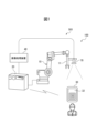
- Fig. 1 shows a system configuration of a teaching system 501 for teaching on calibration or position detection according to a first embodiment.
- the teaching system 501 includes a robot system 100.
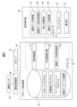
- Fig. 2 shows a functional block diagram of the teaching system 501.
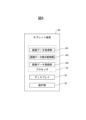
- the robot system 100 includes a robot 10, a robot control device 20 for controlling the robot 10, a teaching operation panel 30, an image processing device 40 connected to the robot control device 20, and a visual sensor 70.
- the visual sensor 70 is attached to the tip of the arm of the robot 10 and is connected to the image processing device 40. By calibrating the visual sensor 70, the robot system 100 is able to detect the position of an object using the visual sensor 70 and handle the object.
- the robot control device 20 (first device) is responsible for performing calibration or position detection using the visual sensor 70.
- the teaching operation panel 30 (second device) has the function of acquiring image data of a predetermined pattern for calibration or position detection from the robot control device 20 (first device), and displaying an image of the predetermined pattern based on the acquired image data on the display 32 of the teaching operation panel 30 (second device) so that the image can be captured by the visual sensor.
- the robot control device 20 controls the operation of the robot 10 according to the robot program or commands from the teaching operation panel 30.
- the robot control device 20 may have a hardware configuration as a general computer having a processor 21, memory (ROM, RAM, non-volatile memory, etc.), a storage unit 22, an operation unit, an input/output interface, a network interface, etc. (see Figure 2).
- the teaching operation panel 30 is connected to the robot control device 20 by wire or wirelessly, and can provide functions for teaching the robot 10 and inputting various settings.
- a teaching device configured with various portable terminal devices may be used as the teaching operation panel 30.
- the teaching operation panel 30 may have a hardware configuration as a general computer having a processor 31, memory (ROM, RAM, non-volatile memory, etc.), a storage device, a display 32, an operation unit 33, an input/output interface, a network interface, etc. (see Figure 2).
- the operation unit may be configured as a touch operation panel integrated with the display 32.
- the robot 10 is a vertical articulated robot, but various types of robots may be used as the robot 10, such as a horizontal articulated robot, a parallel link robot, or a dual-arm robot, depending on the work target.
- the robot 10 can perform the desired work using an end effector attached to the wrist.
- the end effector is an external device that can be replaced depending on the application, such as a hand, a welding gun, or a tool.
- Figure 1 shows an example in which a hand 11 is used as the end effector.
- the image processing device 40 has the function of controlling the visual sensor 70 based on commands from the robot control device 20 (operation control unit 121) and executing image processing (detection, determination, etc.) on the captured images.
- the visual sensor 70 may be a camera that captures grayscale or color images, or a stereo camera or three-dimensional sensor that can obtain distance images or three-dimensional point clouds.
- the image processing device 40 is disposed as a separate device from the robot control device 20, but the functions of the image processing device 40 may be integrated into the robot control device 20.
- the robot control device 20 includes an operation control unit 121, a dimension information calculation unit 122, and an image data storage control unit 123. These functional blocks may be realized by the processor 21 of the robot control device 20 executing software.
- FIG. 2 illustrates a memory unit 22 as a hardware component of the robot control device 20.
- the memory unit 22 is, for example, a storage device formed of a non-volatile memory or a hard disk device.
- the memory unit 22 stores various programs such as a robot program for controlling the robot 10, a calibration program, a position detection program (a program for measuring or detecting the position of an object using a predetermined pattern such as a marker), and various setting information.
- the memory unit 22 also holds image data of a predetermined pattern that can be used for calibration or position detection.
- the motion control unit 121 controls the motion of the robot 10 according to the robot program or according to commands from the teaching operation panel 30.
- the robot control device 20 is equipped with a servo control unit (not shown) that performs servo control on the servo motors of each axis according to commands for each axis generated by the motion control unit 121.
- the teaching operation panel 30 includes an image data acquisition unit 131, an image data display control unit 132, a brightness adjustment unit 133, and an image data registration unit 134. These functional blocks may be realized by the processor 31 executing software.
- the image data acquisition unit 131 has a function of acquiring image data of a predetermined pattern for calibration or position detection from the robot control device 20.
- the image data display control unit 132 has a function of displaying the acquired image of the predetermined pattern on the display 32.
- the operator can use the teaching operation panel 30 as a calibration tool or a tool for detecting the position of an object by displaying an image of a predetermined pattern such as a dot pattern or marker on the teaching operation panel 30.
- the robot control device 20 calculates dimensional information based on information related to the display 32 of the teaching operation panel 30, and stores the information in association with image data of the dot pattern.
- the dimensional information calculation unit 122 of the robot control device 20 can calculate, for example, from the number of pixels at the lattice point interval in the image data of the dot pattern and information on the resolution and size of the display 32 of the teaching pendant 30, what the dimension of the dot interval will be when the dot pattern is displayed on the display 32.
- the dimensional information calculation unit 122 may be configured to control the execution of the following procedure.
- Step b1 The input of information (resolution and size) regarding the display 32 is accepted via the teaching pendant 30.
- Step b2 The above-mentioned dimensional information is calculated based on the image data of the dot pattern and information related to the display 32.
- the calculated dimensional information is stored in the storage unit 22 in association with the image data of the dot pattern.
- the image data storage control unit 123 has a function of associating image data of a dot pattern with dimensional information and storing the associated data in the storage unit 22.
- the dimensions of the dot spacing when displayed on the display 32 for each dot pattern (image data) may be calculated and associated with the image data, as shown in Table 1 below. This allows the teaching pendant 30 to be used as multiple types of calibration jigs with different dot spacing.
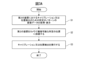
- FIG. 3A shows the overall flow of the process for teaching a specific pattern for calibration or position detection.
- an operator executes a process for acquiring and displaying image data of a specific pattern for calibration or position detection on the teaching operation panel 30 (second device) (step 1).
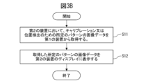
- FIG. 3B is a flowchart showing the process in step S1 in FIG. 3A.
- the image data acquisition unit 131 of the teaching operation panel 30 acquires image data of a predetermined pattern for calibration or position detection from the robot control device 20 (first device) (step S11).
- the image data acquisition unit 131 may be configured to display a list of multiple patterns on the display 32 and accept a user operation to select desired image data from the list.
- the image data display control unit 132 of the teaching pendant 30 displays the image of the predetermined pattern acquired from the robot control device 20 on the display 32 (step S12). This makes it possible for the teaching pendant 30 to be used as a jig for calibration or position detection.
- the worker then places the teaching pendant 30 (second device) on which the predetermined pattern is displayed at a predetermined position for calibration or position correction where it can be imaged by the visual sensor 70 (step S2).
- the worker then causes the visual sensor 70 to image the teaching pendant 30 on which the image of the predetermined pattern is displayed, and causes the robot control device 20 to perform calibration or position detection (step S3).
- the robot control device 20 (first device) has dimensional information for when the dot pattern is displayed on the teaching pendant 30, and can use that dimensional information when performing calibration.
- FIG. 4 shows the state where an image of a dot pattern 301 for calibration is displayed on the display 32 of the teaching operation panel 30 in step S1 above.
- the dot pattern 301 shown in FIG. 4 satisfies the above-mentioned requirements (a1) to (a3) as a dot pattern for performing calibration.
- the dot spacing d on the display 32 when the dot pattern 301 is displayed as in FIG. 4 is known to the robot control device 20, which is responsible for performing the calibration. Therefore, the robot control device 20 can appropriately perform the calibration using the value of the dot spacing d held by the robot control device 20.
- a dot pattern 301 may be used to detect the position of an object or to set a coordinate system.
- the operator can perform calibration or position detection simply by operating the teaching operation panel 30 to download image data of a specified pattern from the robot control device 20 and display it. Therefore, the operator does not need to perform the time-consuming task of retrieving jigs for calibration or position detection from a storage location and setting them up, as was done in the past.
- the worker can obtain image data of dot patterns of a size that matches the execution environment from the robot control device 20 at any time, display it on the teaching operation panel 30, and use it for teaching.
- the operator can perform calibration or position detection by displaying an image of a predetermined pattern on the teaching operation panel 30 whenever necessary.
- the operator can also activate the function of the image data acquisition unit 131 whenever necessary to download image data of a predetermined pattern from the robot control device 20 and display it overlapping on the operation screen 401 for teaching.
- the example in FIG. 5 shows a case where a dot pattern 301 is displayed overlapping on the operation screen 401 for teaching.
- the brightness adjustment unit 133 of the teaching operation panel 30 has a function of receiving information on the brightness of an image captured by the visual sensor 70 of the teaching operation panel 30 displaying an image of a predetermined pattern from the robot control device 20 (calibration program or position detection program) and adjusting the brightness of the image of the predetermined pattern displayed on the display 32. For example, when the information from the robot control device 20 indicates that the captured image is too dark, the brightness adjustment unit 133 increases the brightness of the image of the predetermined pattern on the display 32. Alternatively, when the information from the robot control device 20 indicates that the captured image is too bright, the brightness adjustment unit 133 decreases the brightness of the image of the predetermined pattern on the display 32.
- This function makes it possible to automatically adjust the brightness of the predetermined pattern to an appropriate state regardless of the lighting environment in the work space.
- the operator does not need to perform time-consuming tasks such as adjusting the lighting device in the work space in order to adjust the brightness of the image of the predetermined pattern captured by the visual sensor 70.
- the brightness adjustment unit 133 may also have a function for adjusting the brightness of the display of the image of the specified pattern by manual operation. Even in this case, the operator can adjust the brightness of the image of the specified pattern displayed on the teaching operation panel 30 to an appropriate state by looking at the state of the image captured by the visual sensor 70. The operator does not need to carry out time-consuming tasks such as adjusting the lighting equipment in the work space in order to adjust the brightness of the image of the specified pattern captured by the visual sensor 70.
- the teaching operation panel 30 (second device), which has the function of displaying an image of a specific pattern, has the function of appropriately adjusting the brightness of the display of the image of the specific pattern in this way, so that the worker does not need to adjust the brightness of the lighting in the work space. Therefore, the burden on the worker when performing calibration or position detection is reduced, and the work can be carried out more efficiently.
- the image data registration unit 134 provides a function for registering new image data of a specified pattern for calibration or position detection to the robot control device 20 (first device) that stores image data of a specified pattern.
- the image data registration unit 134 provides a function for registering any image data among the image data stored in the teaching operation panel 30 (or an external storage device connected to the teaching operation panel 30) in the robot control device 20 as new image data for calibration or position detection.
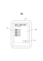
- FIG. 6 shows an example of an image data registration screen 402 displayed on the display 32 of the teaching operation panel 30 by the function of the image data registration unit 134.
- the registration screen 402 displays a list of image data stored in the teaching operation panel 30 (or an external storage device connected to the teaching operation panel 30). The operator can select the desired image data from the displayed list of image data and press the OK button 411 to register the selected image data in the storage unit 22 of the robot control device 20 as image data of a new pattern.
- the image data storage control unit 123 of the robot control device 20 provides a function of accepting a registration request from the image data registration unit 134 and storing the new image data in the storage unit 22.
- the image data registration unit 134 may be configured to accept registration of information regarding the dimensions of the pattern when accepting registration of image data of a new pattern.
- the dimensional information may be, for example, the number of pixels between dots in a dot pattern, or the dimension (millimeters) of the dot spacing on a specific display, as described above.
- the dimensional information may be information about the size of the marker (for example, the size (number of dots) of circle C, the size (square millimeters) of circle C when it is displayed on a specific display, etc.). This allows the robot control device 20 to hold information that associates image data with dimensional information, such as that shown in Table 1 above, even for new image data.
- the above-described embodiment is an example of a configuration in which image data of a predetermined pattern held by the robot control device 20 (first device) is downloaded to the teaching operation panel 30 (second device) and displayed, but the second device that downloads and displays the image data of the predetermined pattern is not limited to the teaching operation panel 30.
- the configuration may be such that the image data of the predetermined pattern is downloaded and displayed by a portable terminal device separate from the teaching operation panel 30.
- the terminal device can be positioned as a teaching device for performing calibration or position detection-related teaching.
- FIG. 7 shows an example of the equipment configuration of such a teaching system 501A.
- a tablet terminal 80 separate from the teaching pendant 30 downloads and displays image data of a predetermined pattern.
- FIG. 8 shows a functional block diagram of the tablet terminal 80 in this system configuration.
- the tablet terminal 80 includes an image data acquisition unit 181, an image data display control unit 182, and an image data registration unit 184.
- the functions of the image data acquisition unit 181, the image data display control unit 182, and the image data registration unit 184 are equivalent to the functions of the image data acquisition unit 131, the image data display control unit 132, and the image data registration unit 134 of the teaching pendant 30 described above.
- FIG. 8 also shows a display 82 and an operation unit 83 as hardware components of the tablet terminal 80.
- the tablet terminal 80 may have a hardware configuration as a general computer having a processor 81, memory (ROM, RAM, non-volatile memory, etc.), a storage device, a display 82, an operation unit 83, an input/output interface, a network interface, etc.
- the operation unit may be configured as a touch operation panel integrated with the display.
- the tablet terminal 80 may be connected to the robot control device 20 so as to be able to communicate with it, or it may not be able to communicate with it. If the tablet terminal 80 is not able to communicate with the robot control device 20, for example, the worker may download and store image data of the robot control device 20 in a USB memory. The worker may then connect this USB memory to the tablet terminal 80, and obtain and display image data of a desired pattern on the tablet terminal 80.
- the robot control device 20 may store information about the display 82 of the tablet terminal 80 in addition to information about the display 32 of the teaching operation panel 30. This allows the robot control device 20 to calculate and store the size of the dot spacing of the dot pattern on the display 82 from the number of pixels of the dot spacing in the image data of the dot pattern and the resolution and size of the display 82 of the tablet terminal 80. This allows the robot control device 20 to store dimensional information of the dot spacing when the dot pattern is displayed on the teaching operation panel 30 and dimensional information of the dot spacing when the dot pattern is displayed on the tablet terminal 80, in association with the image data, as shown in Table 2 below.
- the information shown in Table 2 can also be expanded to accommodate three or more types of terminal devices.
- the dot spacing when the dot pattern is displayed on three or more types of terminal devices can be calculated based on the number of pixels for the dot spacing in the dot pattern and the display information (resolution, size) of the three or more types of terminal devices.
- the robot control device 20 when the robot control device 20 is configured to hold dimensional information for multiple types of displays, the robot control device 20 (processor 21) may be configured to obtain information about which display is to be used in performing calibration or position detection through user input, for example, via the teaching operation panel 30.
- the marker 302 is a type of marker that includes mutually perpendicular straight lines a and b and a circle C of a known size.
- the marker 302 is used as follows. When detecting the position of an object using the marker 302, the worker calibrates the visual sensor 70 in advance. Then, the worker operates the tablet terminal 80 to download image data of the marker 302 from the robot control device 20 and display it on the display 82 (step S1).
- the worker places the tablet terminal 80 on which the marker 302 is displayed at a predetermined position of the measurement object (workbench, machine tool, etc.) (step S2), and causes the robot control device 20 to execute a position detection program (step S3).
- the position detection program grasps the three-dimensional position of the marker 302 based on the detected position of the marker 302 on the captured image, and obtains the three-dimensional position of the measurement object.
- a stereo measurement method using a visual sensor 70 may be used to measure the three-dimensional position of the marker 302. Therefore, even when performing such position detection, the worker does not need to take out a marker jig or a printed copy of the marker stored in a separate location and install it on the target.
- the robot control device 20 may associate the dimensional information with the image data of the marker and store the dimensional information when the marker is displayed on the display 82 of the tablet terminal 80 (second device), and use this dimensional information when detecting the position of the object.
- the second device that displays an image of the predetermined pattern may be a machine tool used together with the robot 10.
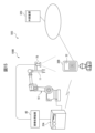
- FIG. 10 shows a schematic diagram of the equipment configuration in this case.
- this case corresponds to an application example in which the robot 10 is mounted on a cart or AGV and placed at a predetermined position relative to the machine tool 90 to load and unload workpieces from the machine tool 90.
- the machine tool 90 incorporates a control device (numerical control device) 91 with an integrated display 92.
- the control device 91 can download and display image data of the predetermined pattern from the robot control device 20, for example, via a network.
- image data of the predetermined pattern may be registered in advance in the memory unit of the control device 91.
- the 10 shows a state in which the marker 302 is displayed on the display 92 of the control device 91.
- the display 92 of the control device 91 is attached to a fixed position on the machine tool 90, so that the marker 302 can be used as an indicator of the position of the machine tool 90 by displaying the marker 302 at a predetermined position on the display 92.
- the worker operates the control device 91 to display the marker 302 on the display 92.
- the robot control device 20 measures the positional relationship between the robot 10 and the machine tool 90 by capturing an image of the marker 302 displayed on the display 92 with the visual sensor 70.
- the robot control device 20 can hold information regarding the specifications of the display 92 of the control device 91 (resolution, screen size, etc.) and use the dimensional information of the marker 302 when displayed on the display 92 based on the image data of the marker 302 for detection.
- the processor of the control device 91 can execute the functions of an image data acquisition unit 181, an image data display control unit 182, and an image data registration unit 184, as described above with reference to FIG. 8 for the tablet terminal 80.
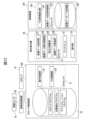
- FIG. 11 is a diagram showing the equipment configuration of a teaching system 502 according to the second embodiment.
- the teaching system 503 includes a robot system 100A.
- the second device that displays an image of a predetermined pattern for calibration or position detection is the teaching pendant 30, and the first device that provides image data to the second device (teaching pendant 30) is an external device other than the robot control device 20A.
- the external device is another control device (numerical control device, robot control device, etc.) 220 arranged in the factory where the robot system 100A is arranged. It is assumed that the teaching pendant 30 can communicate with the control device 220 by wire or wirelessly via a network in the factory.
- the control device 220 may have a hardware configuration as a general computer having a processor 224, memory (ROM, RAM, non-volatile memory, etc.), a storage unit 225, a display unit, an operation unit, an input/output interface, a network interface, etc. (see FIG. 12).
- the control device 220 (first device) holds image data of a predetermined pattern for calibration or position detection in a format similar to that of the robot control device 20 in the first embodiment. Therefore, with regard to a dot pattern, the control device 220 holds dimensional information of the dot spacing when the dot pattern is displayed on the display 32 of the teaching operation panel 30 in association with the image data of the dot pattern. In this embodiment, in order to provide the dimensional information of the dot spacing to the robot control device 20A that is responsible for calibration or position detection, an image showing the dimensional information is displayed on the display 32 of the teaching operation panel 30 together with an image of the dot pattern.
- the control device 220 includes a dimension information calculation unit 221 and an image data storage control unit 222.
- the dimension information calculation unit 221 and the image data storage control unit 222 have functions equivalent to the dimension information calculation unit 122 and the image data storage control unit 123 of the robot control device 20 of the first embodiment. That is, the dimension information calculation unit 221 and the image data storage control unit 222 can execute the same processes as the above-mentioned (steps b1) to (steps b3) in advance and store image data and dimension information of a predetermined pattern in the storage unit 225.
- the storage unit 225 is a storage device configured with a non-volatile memory or a hard disk, etc., and stores image data and dimension information of a predetermined pattern in addition to programs and various setting information related to the control of the machine in the control device 220.
- the image data acquisition unit 131 of the teaching operation panel 30 has a function of downloading image data and dimensional information of a specified pattern from the memory unit 225 of the control device 220.
- the image data display control unit 132 and brightness adjustment unit 133 have the same functions as those described above in relation to the first embodiment.
- the image data registration unit 134 provides the control device 220 with a function for newly registering image data of a specified pattern for calibration or position detection.
- the robot control device 20A includes an operation control unit 121 and a dimension recognition unit 124.
- the storage unit 22 stores a robot program, a calibration program, a position detection program, and various other setting information.
- the dimension recognition unit 124 provides a function for recognizing dimensions from an image of dimensional information displayed together with an image of a specified pattern.
- FIGS. 13A and 13B show examples of images showing dimensional information about dot spacing together with a dot pattern 301 displayed on the display 32 of the teaching pendant 30.
- FIG. 13A shows an example in which an image G1 showing the numerical value of the dot spacing is displayed as dimensional information.
- FIG. 13B shows an example in which an image G2 in which the numerical value of the dot spacing is coded as dimensional information is displayed.
- the dimensional information calculation unit 221 may have a function for coding the calculated dot spacing dimension as in image G2.
- the control device 220 may store such image G1 or image G2 as dimensional information.
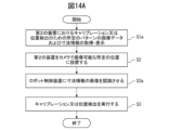
- FIG. 14A shows the overall flow of the process related to teaching a specified pattern for calibration or position detection.
- the flow is explained focusing on the process when a dot pattern is used as the specified pattern.
- the operator executes a process for acquiring and displaying image data and dimensional information of the specified pattern for calibration or position detection on the teaching operation panel 30 (second device) (step S1a).
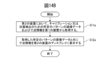
- FIG. 14B is a flowchart showing the processing content in step S1a of FIG. 14A.
- the image data acquisition unit 131 of the teaching pendant 30 acquires image data of a predetermined pattern for calibration or position detection, and dimensional information from the control device 220 (first device) (step S11a).
- the control device 220 holds image data of multiple types of patterns
- the image data acquisition unit 131 may be configured to display a list of multiple patterns on the display 32 and accept a user operation to select desired image data from the list.
- the image data display control unit 132 of the teaching pendant 30 causes the image and dimensional information of the predetermined pattern acquired from the control device 220 to be displayed on the display 32 (step S12a). This makes it possible for the teaching pendant 30 to be used as a jig for calibration or position detection.
- the operator then places the teaching pendant 30, on which an image showing dimensional information is displayed together with an image of a dot pattern, at a predetermined position for calibration and position correction where an image can be captured by the visual sensor 70 (step S2).
- the operator causes the robot control device 20A to recognize the dimensional information of the dot interval (step S2a).
- the operator can cause the robot control device 20A to recognize the dot interval by any of the following methods (c1) to (c3).
- (c1) An operator directly inputs the data into the setting items of the calibration program.
- the robot control device reads and recognizes the numerical values on the image.
- the robot control device reads and recognizes the code information on the image.
- the above method (c1) is an effective method when an image G1 showing the numerical value of the dot spacing is displayed together with an image of a dot pattern, as shown in FIG. 13A.
- the worker can see the image of the dimensional information displayed together with the image of the dot pattern, grasp the dot spacing, and directly input it into the setting item of the calibration program.
- FIG. 18 shows an example of an execution screen 450 of the calibration program.
- the execution screen 450 displays an input field 451 for specifying the dot spacing together with an image G5 captured by the visual sensor 70 of the teaching pendant 30 placed in a predetermined position.
- the worker can input the dot spacing by directly entering a numerical value into the input field 451, or by specifying the dot spacing from a menu list of numerical values.
- the worker can then perform a predetermined operation on the execution screen 450 to execute the calibration and check the results.
- the above method (c2) is an effective method when displaying an image G1 showing the numerical value of the dot spacing together with an image of a dot pattern, as shown in FIG. 13A.
- the dimension recognition unit 124 of the robot control device 20A has the function of recognizing the numbers of the dimensional information from an image captured by the visual sensor 70 of the teaching operation panel 30 in a state in which the image G1 of the dimensional information is displayed on the display 32 together with the dot pattern, and providing the numbers to the calibration program.
- Various character recognition techniques known in the field can be used to recognize the numbers from the image.
- the above method (c3) is an effective method when displaying an image G2 of a code representing the dot spacing together with an image of a dot pattern, as shown in FIG. 13B.
- the dimension recognition unit 124 of the robot control device 20A has a function of reading the code from an image captured by the visual sensor 70 of the teaching operation panel 30 in a state in which an image G2 of dimensional information is displayed on the display 32 together with a dot pattern, and providing the code to the calibration program.
- the code may be a one-dimensional code or a two-dimensional code.
- Various code recognition technologies known in the field can be used to recognize the code.
- the worker causes the visual sensor 70 to capture an image of the dot pattern and causes the robot control device 20A to perform calibration or position detection (step S3).
- the process flow shown in FIG. 3A-FIG. 3B in the first embodiment can be applied instead of the process flow of FIG. 14A-FIG. 14B described above.
- the control device 220 first device holds configuration information (dimensional information, etc.) of the marker together with the image data of the marker.
- the teaching operation panel 30 may acquire the configuration information together with the image data of the marker from the control device 220 (first device), and provide the acquired configuration information to the robot control device 20A so that it can be used for teaching the marker.
- the teaching operation panel 30 may display an image showing the dimensional information of the marker on the display 32 together with the image of the marker.
- the robot control device 20A dimension recognition unit 124) can recognize the dimensional information from the captured image in which the visual sensor 70 captures an image showing the marker and the dimensional information.
- the operator can perform calibration or position detection by displaying an image of a specific pattern on the teaching operation panel 30 whenever necessary.
- the operator does not need to perform the time-consuming task of retrieving a jig for calibration or position detection from a storage location and setting it up, as was done in the past.
- By displaying an image showing dimensional information together with an image of the specific pattern it is also possible to have the robot control device 20A recognize the dimensional information, so the operator can perform calibration simply by operating the teaching operation panel 30 to download image data of the specific pattern from the control device 220 and display it.
- the second device that downloads and displays the image data of the specified pattern is the teaching operation panel 30, but a portable terminal device other than the teaching operation panel 30 may be used as the second device.
- the terminal device is positioned as a teaching device for teaching regarding calibration or position detection.
- the control device 220 associates the dimensional information of each dot interval when the image of the dot pattern is displayed on each terminal device, as described in Table 2 of the first embodiment, with the image data of the dot pattern and stores it.
- control device 220 may be configured to identify the terminal device that requested the image data and provide the terminal device with the dimensional information corresponding to the terminal device along with the image data of the specified pattern.
- the second device that downloads and displays the image data of the specified pattern may be a machine tool.
- images of a specific pattern can be displayed on various terminal devices other than the teaching pendant 30, making them available for calibration and position detection.
- FIG. 11 shows an example in which the first device that provides image data of a predetermined pattern is the machine control device 220
- the first device that provides image data of a predetermined pattern can be various external devices.
- the first device that provides image data of a predetermined pattern can be the teaching operation panel 30 used by the worker, or a computer or cloud that is network-connected to another terminal device.
- the teaching operation panel 30 displays the dimensional information received from the control device 220 together with an image of a specified pattern, but the teaching operation panel 30 may also transmit the dimensional information received from the control device 220 to the robot control device 20A so that the robot control device 20A can use it for calibration and position detection.
- the first and second embodiments described above are configuration examples in which a first device providing image data of a predetermined pattern has a function for generating dimensional information of the dot interval when the dot pattern is displayed on a second device based on information about the display of the second device displaying the image data of the predetermined pattern.
- the second device displaying the image data of the predetermined pattern has a function for generating dimensional information of the dot interval.
- FIG. 15 is a diagram showing the equipment configuration of a teaching system 503 according to the third embodiment.
- the teaching system 503 includes a robot system 100B.
- the second device that displays an image of a predetermined pattern for calibration or position detection is a teaching operation panel 30B
- the first device that provides image data to the second device is an external device 320 that is network-connected to the teaching operation panel 30B.
- the network may include an in-house network such as a LAN (Local Area Network) or a commercial network such as the Internet.
- the external device 320 may include various devices and computer systems, such as a control device arranged in the same factory as the robot system 100B, a computer, a server connected via a commercial network, and a cloud.
- the external device 320 may have a hardware configuration as a general computer having a processor 321, memory (ROM, RAM, non-volatile memory, etc.), a storage unit 322, a display unit, an operation unit, an input/output interface, a network interface, etc. (see FIG. 16).
- FIG. 16 shows a functional block diagram of the robot control device 20A, teaching operation panel 30B, and external device 320 in the teaching system 503 according to the third embodiment.
- the external device 320 holds image data of a predetermined pattern for calibration or position detection in the memory unit 322.
- the teaching operation panel 30B has the functions of an image data acquisition unit 131, an image data display control unit 132, a brightness adjustment unit 133, and an image data registration unit 134. These functions have been described above, so details will be omitted.
- the image data acquisition unit 131 has the function of acquiring image data of a specified pattern from the external device 320.
- the image data registration unit 134 provides a function of registering new image data that can be used for calibration or position detection in the external device 320.
- the teaching operation panel 30B according to this embodiment further includes a dimension information generation unit 135.
- the dimensional information generating unit 135 has a function of calculating, based on the resolution and size information of the display 32, the size of the dot spacing of the dot pattern when the image data of the dot pattern downloaded from the external device 320 is displayed on the display 32. Specifically, the dimensional information generating unit 135 analyzes the image of the dot pattern and determines the number of pixels of the dot spacing. Then, based on the resolution and size of the display 32, the dimensional information generating unit 135 calculates the size of the dot spacing on the display 32 and generates dimensional information.
- the dimensional information is, for example, a numerical value or a code.
- the image data display control unit 132 can display an image showing the dimensional information on the display 32 together with the image of the dot pattern.
- Examples of the display format in this case include displaying an image of numerical values showing the dimensional information together with the image of the dot pattern, as shown in Figures 13A and 13B, and displaying an image in which the dimensional information is coded together with the image of the dot pattern.
- the robot control device 20A may have the same functional configuration as the robot control device 20A in the second embodiment described above.
- FIG. 17A shows the overall flow of processing related to teaching a specified pattern for calibration or position detection.
- the flow is explained focusing on the processing when a dot pattern is used as the specified pattern.
- the operator acquires image data of the specified pattern for calibration or position detection on the teaching operation panel 30B (second device) and executes processing to display it together with dimensional information (step S1b).
- FIG. 17B is a flow chart showing the processing content in step S1b of FIG. 17A.
- the image data acquisition unit 131 of the teaching pendant 30B acquires image data of a predetermined pattern for calibration or position detection from the external device 320 (first device) (step S11).
- the processor 321 of the external device 320 has a function of sending image data in the memory unit 322 to the teaching pendant 30B in response to a request from the teaching pendant 30B.
- the image data acquisition unit 131 may be configured to display a list of multiple patterns on the display 32 and accept a user operation to select desired image data from the list.
- the dimensional information generating unit 135 of the teaching pendant 30B calculates dimensional information of the dot spacing when the dot pattern is displayed on the display 32 based on the number of pixels between dots in the acquired image data of the dot pattern and the resolution and size information of the display 32 (step S11b). Then, the image data display control unit 132 causes the display 32 to display an image representing the dimensional information together with the image of the dot pattern (step S12a).
- the operator then places the teaching pendant 30B, on which an image showing dimensional information is displayed together with an image of a dot pattern, at a predetermined position for calibration and position correction where an image can be captured by the visual sensor 70 (step S2).
- the operator causes the robot control device 20A to recognize the dimensional information of the dot spacing (step S2a).
- the operator may cause the robot control device 20A to recognize the dot spacing using any of the methods (c1) to (c3) described in the second embodiment.
- the worker causes the visual sensor 70 to capture an image of the dot pattern and perform calibration or position detection (step S3).
- the process flow shown in Figures 3A-3B in the first embodiment can be applied instead of the process flow of Figures 17A-17B described above.
- the external device 320 first device stores configuration information of the marker together with image data of the marker.
- the teaching operation panel 30B second device may obtain the configuration information together with image data of the marker from the external device 320 (first device), and provide the obtained configuration information to the robot control device 20A so that it can be used for teaching of the marker.
- the second device that displays the image of the specified pattern is configured to calculate and display the dot spacing of the dot pattern, so there is no need to generate and store dimensional information in advance in the first device that provides the image data of the specified pattern.
- the operator can perform calibration or position detection by displaying an image of a specific pattern on the teaching operation panel 30B whenever necessary.
- the operator does not need to perform the time-consuming task of retrieving a jig for calibration or position detection from a storage location and setting it up, as was done in the past.
- the robot control device 20A recognize the dimensional information, so the operator can perform calibration simply by operating the teaching operation panel 30B to download image data of the specific pattern from the external device 320 and display it.
- the second device that downloads and displays an image of a predetermined pattern from the first device is the teaching operation panel 30B, but this is an example, and the second device that downloads an image of a predetermined pattern from the first device (external device 320), generates dimensional information, and displays it together with the image of the predetermined pattern may be a portable terminal device separate from the teaching operation panel 30B.
- the terminal device is positioned as a teaching device for performing calibration or position detection-related teaching.
- the configuration has been described where the teaching operation panel 30B displays the calculated dimensional information together with an image of a specified pattern, but the teaching operation panel 30B may also transmit the calculated dimensional information to the robot control device 20A so that the robot control device 20A can use it for calibration and position detection.
- the burden on the worker when performing calibration or position detection using a specified pattern is reduced, and these tasks can be performed efficiently.
- the functional distribution shown in the functional block diagrams of the above-mentioned embodiments is an example, and various modifications of the functional distribution are possible.
- the teaching operation panel 30 shown in the first embodiment does not need to have the functions of the brightness adjustment unit 133 and the image data registration unit 134.
- a configuration example is also possible in which a first device that has the function of providing image data also has an application program that displays image data along with image data of a predetermined pattern, and provides such an application along with the image data to a second device that has the function of displaying the predetermined pattern.
- This application program may have a function of obtaining display information (resolution, size, etc.) of the device that executes this application, and calculating dimensional information when the predetermined pattern is displayed.
- the second device that executes this application may display an image (an image of numerical values or codes) that represents the calculated dimensional information together with an image of the pattern, as shown in Figures 13A-13B.
- the second device that executes this application may provide the calculated dimensional information to the first device.
- the robot control device 20 which serves as a first device, has image data of a predetermined pattern together with an application program for displaying the image data.
- the robot control device 20 transmits the application program together with the image data to the tablet terminal 80, which serves as a second device.
- the tablet terminal 80 executes the application program, displays an image of the predetermined pattern, and calculates dimensional information.
- the tablet terminal 80 may display an image (numerical values or codes) representing the dimensional information together with the image of the predetermined pattern.
- the tablet terminal 80 may transmit the calculated dimensional information to the robot control device 20.
- the robot control device 20 can use the dimensional information recognized from the image captured by the visual sensor 70 or provided by the tablet terminal 80 for calibration or position detection.
- the functional blocks in the functional block diagrams relating to the robot control device, teaching operation panel, tablet terminal, and external device may be realized by one or more processors of these devices executing various software stored in a storage device, or may be realized by a configuration mainly based on hardware such as an ASIC (Application Specific Integrated Circuit).
- ASIC Application Specific Integrated Circuit
- the programs for executing the teaching processes for calibration or position detection in the above-mentioned embodiments can be recorded on various computer-readable recording media (e.g., semiconductor memories such as ROM, EEPROM, and flash memory, magnetic recording media, and optical disks such as CD-ROM and DVD-ROM).
- a teaching system (501, 501A, 502, 503) for teaching on calibration or position detection, A first processor; A first device (20, 220, 320) having a storage unit that stores image data for the calibration or position detection; A second processor; and a second device (30, 80, 30B) having a display; The second processor of the second device acquiring the image data from the first device; displaying an image represented by the image data on the display so as to be captured by a visual sensor in performing the calibration or position detection; Teaching system (501, 501A, 502, 503).
- the first device is a robot control device (20) that performs the calibration or position detection, The first processor of the first device performing the calibration or position detection based on a captured image obtained by capturing the image displayed on the display of the second device by the visual sensor;
- the storage unit of the first device (20) stores information about a size of the image on a display of the second device when the image represented by the image data is displayed on the display of the second device in association with the image data;
- the storage unit of the first device (220) holds information about a size of an image represented by the image data when the image is displayed on the display of the second device (30) in association with the image data;
- the second processor receives information regarding the dimensions together with the image data from the first device (220);
- the second processor (1) displaying, on the display, an image showing information related to the dimensions together with the image represented by the image data; (2) transmitting information regarding the dimensions to the robot controller;
- the teaching system (502) according to claim 4, which executes one of the processes.
- the second processor calculates information regarding dimensions of the image based on the image data when the image is displayed on the display based on the acquired image data and information regarding a resolution and a size of the display; The second processor, (1) displaying, on the display, an image showing information related to the dimensions together with the image represented by the image data; (2) transmitting information about the calculated dimensions to the robot controller;
- Appendix 7 The teaching system (502, 503) of appendix 5 or 6, wherein the other device is either a machine control device, an external device, or a cloud.
- the second processor displays on the display an image showing information related to the dimensions together with an image represented by the image data;
- the second device is a teaching pendant (30, 30B) connected to a robot control device,
- the second processor of the second device obtains information regarding the brightness of an image captured by the visual sensor of the second device displaying an image represented by the image data on the display from the robot control device, and adjusts the display brightness of the display displaying the image based on the information regarding the brightness.
- the storage unit of the first device further stores an application program for displaying an image represented by the image data;
- the second processor obtains the application program together with the image data from the first device;
- the application program further has a function of calculating information regarding dimensions when an image represented by the image data is displayed on a display of a device that executes the application, based on information regarding the display of the device;
- the second processor (1) displaying an image showing the information about the dimensions obtained by executing the application together with an image represented by the image data; (2) transmitting information regarding the dimensions to the first device;
- the teaching system (501, 501A, 502) according to Appendix 13, which executes any one of the processes above.
- a teaching device (30, 80, 30B) used for teaching regarding calibration or position detection, A display (32, 82); A processor (31, 81), The processor (31, 81) Acquiring image data for the calibration or position detection from an external device; A teaching device (30, 80, 30B) displays an image represented by the image data on the display to be captured by a visual sensor in performing the calibration or position detection.
- the processor further acquires, from the external device, information regarding a size of the image represented by the image data when the image is displayed on the display;
- the processor (1) displaying, on the display, an image showing information related to the dimensions together with the image represented by the image data; (2) transmitting information about the dimensions to a robot control device that controls the calibration or position detection;
- the teaching device (30) according to claim 15, which executes any one of the processes above.
- the processor calculates information about dimensions of the image based on the image data when the image is displayed on the display based on the acquired image data and information about a resolution and a size of the display;
- the processor (1) displaying, on the display, an image showing information related to the dimensions together with the image represented by the image data; (2) transmitting information about the calculated dimensions to a robot control device that controls the calibration or position detection;
- the processor (31, 81) further A teaching device (30, 80, 30B) described in any one of appendices 15 to 17, which registers new image data of a predetermined pattern that can be used for the calibration or position detection and information regarding the dimensions of the new image data in a memory unit of the external device based on a user operation.
- the external device is a robot control device (20, 20A) that performs the calibration or position detection,
- the processor (31) obtains information regarding the brightness of an image captured by the visual sensor of the teaching device displaying an image represented by the image data on the display from the robot control device, and adjusts the display brightness of the display showing the image based on the information regarding the brightness.
- the storage unit stores information about a size of the image on a display of the external device when the image represented by the image data is displayed on the display of the external device in association with the image data; 21.
- Appendix 22 The processor (21) A robot control device (20) as described in Appendix 19, which calculates information regarding the dimensions based on the image data and information regarding the resolution and size of the display of the external device.
- Appendix 23 an image represented by the image data is displayed on a display of the external device together with information regarding a size of the image when the image is displayed on the display;
- the processor (21) Recognizing information regarding the size from a captured image obtained by capturing an image represented by the image data and an image represented by the information regarding the size displayed on the display of the external device by the visual sensor;
- a robot control device (20A) as described in Appendix 20, wherein information regarding the recognized dimensions is used in performing the calibration or position detection.
- the computer processor A procedure for storing image data for calibration or position detection in a storage unit; transmitting the image data to an external device in response to a request from the external device; A procedure for performing the calibration or position detection based on an image captured by a visual sensor of an image represented by the image data displayed on a display of the external device, and a program for causing the procedure to execute the procedure.
Landscapes
- Engineering & Computer Science (AREA)
- Robotics (AREA)
- Mechanical Engineering (AREA)
- Numerical Control (AREA)
Priority Applications (4)
| Application Number | Priority Date | Filing Date | Title |
|---|---|---|---|
| PCT/JP2023/025931 WO2025013294A1 (ja) | 2023-07-13 | 2023-07-13 | 教示システム、教示装置、ロボット制御装置、及びプログラム |
| JP2025532357A JPWO2025013294A1 (https=) | 2023-07-13 | 2023-07-13 | |
| CN202380100180.8A CN121464019A (zh) | 2023-07-13 | 2023-07-13 | 示教系统、示教装置、机器人控制装置以及程序 |
| TW113121901A TW202502502A (zh) | 2023-07-13 | 2024-06-13 | 教示系統、教示裝置、機器人控制裝置以及程式 |
Applications Claiming Priority (1)
| Application Number | Priority Date | Filing Date | Title |
|---|---|---|---|
| PCT/JP2023/025931 WO2025013294A1 (ja) | 2023-07-13 | 2023-07-13 | 教示システム、教示装置、ロボット制御装置、及びプログラム |
Publications (1)
| Publication Number | Publication Date |
|---|---|
| WO2025013294A1 true WO2025013294A1 (ja) | 2025-01-16 |
Family
ID=94215059
Family Applications (1)
| Application Number | Title | Priority Date | Filing Date |
|---|---|---|---|
| PCT/JP2023/025931 Pending WO2025013294A1 (ja) | 2023-07-13 | 2023-07-13 | 教示システム、教示装置、ロボット制御装置、及びプログラム |
Country Status (4)
| Country | Link |
|---|---|
| JP (1) | JPWO2025013294A1 (https=) |
| CN (1) | CN121464019A (https=) |
| TW (1) | TW202502502A (https=) |
| WO (1) | WO2025013294A1 (https=) |
Citations (6)
| Publication number | Priority date | Publication date | Assignee | Title |
|---|---|---|---|---|
| JPH0843026A (ja) * | 1994-07-29 | 1996-02-16 | Mazda Motor Corp | キャリブレーション装置及びホログラム |
| JPH1049218A (ja) * | 1996-08-07 | 1998-02-20 | Fanuc Ltd | ロボットの位置教示のための移動制御方式 |
| US20120287240A1 (en) * | 2011-05-11 | 2012-11-15 | Tyzx, Inc. | Camera calibration using an easily produced 3d calibration pattern |
| JP2014128845A (ja) * | 2012-12-28 | 2014-07-10 | Fanuc Ltd | ロボットシステム表示装置 |
| JP2019030943A (ja) * | 2017-08-09 | 2019-02-28 | オムロン株式会社 | キャリブレーション方法、キャリブレーションシステム及びプログラム |
| JP2019141935A (ja) * | 2018-02-16 | 2019-08-29 | オムロン株式会社 | コンベアトラッキングシステムおよびキャリブレーション方法 |
-
2023
- 2023-07-13 CN CN202380100180.8A patent/CN121464019A/zh active Pending
- 2023-07-13 JP JP2025532357A patent/JPWO2025013294A1/ja active Pending
- 2023-07-13 WO PCT/JP2023/025931 patent/WO2025013294A1/ja active Pending
-
2024
- 2024-06-13 TW TW113121901A patent/TW202502502A/zh unknown
Patent Citations (6)
| Publication number | Priority date | Publication date | Assignee | Title |
|---|---|---|---|---|
| JPH0843026A (ja) * | 1994-07-29 | 1996-02-16 | Mazda Motor Corp | キャリブレーション装置及びホログラム |
| JPH1049218A (ja) * | 1996-08-07 | 1998-02-20 | Fanuc Ltd | ロボットの位置教示のための移動制御方式 |
| US20120287240A1 (en) * | 2011-05-11 | 2012-11-15 | Tyzx, Inc. | Camera calibration using an easily produced 3d calibration pattern |
| JP2014128845A (ja) * | 2012-12-28 | 2014-07-10 | Fanuc Ltd | ロボットシステム表示装置 |
| JP2019030943A (ja) * | 2017-08-09 | 2019-02-28 | オムロン株式会社 | キャリブレーション方法、キャリブレーションシステム及びプログラム |
| JP2019141935A (ja) * | 2018-02-16 | 2019-08-29 | オムロン株式会社 | コンベアトラッキングシステムおよびキャリブレーション方法 |
Also Published As
| Publication number | Publication date |
|---|---|
| TW202502502A (zh) | 2025-01-16 |
| CN121464019A (zh) | 2026-02-03 |
| JPWO2025013294A1 (https=) | 2025-01-16 |
Similar Documents
| Publication | Publication Date | Title |
|---|---|---|
| US20080013825A1 (en) | Simulation device of robot system | |
| JP4763074B2 (ja) | ロボットのツール先端点の位置の計測装置および計測方法 | |
| CN105269578B (zh) | 指示装置以及机器人系统 | |
| US9519736B2 (en) | Data generation device for vision sensor and detection simulation system | |
| US9199379B2 (en) | Robot system display device | |
| JP6538751B2 (ja) | プログラミング装置及びロボット制御方法 | |
| CN112512754B (zh) | 对工业机器人编程的方法 | |
| US10825193B2 (en) | Position detecting apparatus and computer-readable recording medium | |
| JP6235664B2 (ja) | ロボットの機構パラメータを校正するために使用される計測装置 | |
| CN108687770B (zh) | 自动地生成机器人的动作轨迹的装置、系统以及方法 | |
| JP7366264B2 (ja) | ロボット教示方法及びロボット作業方法 | |
| US20200164520A1 (en) | Image processing device, control method thereof, and program storage medium | |
| JP2016078195A (ja) | ロボットシステム、ロボット、制御装置及びロボットの制御方法 | |
| TWI699264B (zh) | 視覺導引機器手臂校正方法 | |
| WO2025013294A1 (ja) | 教示システム、教示装置、ロボット制御装置、及びプログラム | |
| TW202241660A (zh) | 程式生成裝置及機器人控制裝置 | |
| US12420424B2 (en) | Coordinate system setting system and position/orientation measurement system | |
| TWI853525B (zh) | 記錄有標記位置登記程式的非易失性的電腦可讀取媒體、標記位置登記裝置、方法以及其中使用的標記 | |
| JP7228070B1 (ja) | 点群データ合成装置、点群データ合成プログラム、点群データ合成方法及び点群データ合成システム | |
| JP2024025074A (ja) | マーカ位置登録装置、マーカ位置登録プログラム及びマーカ位置登録方法 | |
| CN116086311B (zh) | 标志检测装置以及机器人示教系统 | |
| JP2024025076A (ja) | マーカ位置登録装置、マーカ位置登録プログラム及びマーカ位置登録方法 | |
| WO2024062535A1 (ja) | ロボット制御装置 | |
| TW202245708A (zh) | 教示裝置、標記計測方法及程式 | |
| US8624929B2 (en) | System for transforming and displaying coordinate datum |
Legal Events
| Date | Code | Title | Description |
|---|---|---|---|
| 121 | Ep: the epo has been informed by wipo that ep was designated in this application |
Ref document number: 23945166 Country of ref document: EP Kind code of ref document: A1 |
|
| ENP | Entry into the national phase |
Ref document number: 2025532357 Country of ref document: JP Kind code of ref document: A |