WO2025013240A1 - 情報管理システムおよび情報管理方法 - Google Patents
情報管理システムおよび情報管理方法 Download PDFInfo
- Publication number
- WO2025013240A1 WO2025013240A1 PCT/JP2023/025724 JP2023025724W WO2025013240A1 WO 2025013240 A1 WO2025013240 A1 WO 2025013240A1 JP 2023025724 W JP2023025724 W JP 2023025724W WO 2025013240 A1 WO2025013240 A1 WO 2025013240A1
- Authority
- WO
- WIPO (PCT)
- Prior art keywords
- duct
- cable
- length
- information
- code
- Prior art date
- Legal status (The legal status is an assumption and is not a legal conclusion. Google has not performed a legal analysis and makes no representation as to the accuracy of the status listed.)
- Ceased
Links
Images



Classifications
-
- H—ELECTRICITY
- H02—GENERATION; CONVERSION OR DISTRIBUTION OF ELECTRIC POWER
- H02G—INSTALLATION OF ELECTRIC CABLES OR LINES, OR OF COMBINED OPTICAL AND ELECTRIC CABLES OR LINES
- H02G1/00—Methods or apparatus specially adapted for installing, maintaining, repairing or dismantling electric cables or lines
- H02G1/06—Methods or apparatus specially adapted for installing, maintaining, repairing or dismantling electric cables or lines for laying cables, e.g. laying apparatus on vehicle
- H02G1/08—Methods or apparatus specially adapted for installing, maintaining, repairing or dismantling electric cables or lines for laying cables, e.g. laying apparatus on vehicle through tubing or conduit, e.g. rod or draw wire for pushing or pulling
-
- G—PHYSICS
- G01—MEASURING; TESTING
- G01B—MEASURING LENGTH, THICKNESS OR SIMILAR LINEAR DIMENSIONS; MEASURING ANGLES; MEASURING AREAS; MEASURING IRREGULARITIES OF SURFACES OR CONTOURS
- G01B3/00—Measuring instruments characterised by the use of mechanical techniques
- G01B3/002—Details
- G01B3/004—Scales; Graduations
-
- G—PHYSICS
- G02—OPTICS
- G02B—OPTICAL ELEMENTS, SYSTEMS OR APPARATUS
- G02B6/00—Light guides; Structural details of arrangements comprising light guides and other optical elements, e.g. couplings
- G02B6/46—Processes or apparatus adapted for installing or repairing optical fibres or optical cables
-
- H—ELECTRICITY
- H02—GENERATION; CONVERSION OR DISTRIBUTION OF ELECTRIC POWER
- H02G—INSTALLATION OF ELECTRIC CABLES OR LINES, OR OF COMBINED OPTICAL AND ELECTRIC CABLES OR LINES
- H02G1/00—Methods or apparatus specially adapted for installing, maintaining, repairing or dismantling electric cables or lines
- H02G1/06—Methods or apparatus specially adapted for installing, maintaining, repairing or dismantling electric cables or lines for laying cables, e.g. laying apparatus on vehicle
-
- H—ELECTRICITY
- H02—GENERATION; CONVERSION OR DISTRIBUTION OF ELECTRIC POWER
- H02G—INSTALLATION OF ELECTRIC CABLES OR LINES, OR OF COMBINED OPTICAL AND ELECTRIC CABLES OR LINES
- H02G9/00—Installations of electric cables or lines in or on the ground or water
- H02G9/06—Installations of electric cables or lines in or on the ground or water in underground tubes or conduits; Tubes or conduits therefor
Definitions
- This disclosure relates to an information management system and an information management method.
- Patent Document 1 discloses a method of providing a recording means for recording coded information related to the installation of an optical cable on or near the installed optical cable, and recording and reading out the information related to the installation of the optical cable at the installation site.
- the information management system of the present disclosure includes: An information management system for calculating the length of a duct in which a cable is laid, a first code is attached to a first end in a longitudinal direction of the duct, and first position information indicating a position of the first end is stored in the first code;
- the information management system includes: an acquisition unit that acquires the first position information after the duct is installed; A calculation unit calculates a length of the laid duct based on the first position information.
- the information management method of the present disclosure includes: 1. An information management method for calculating a length of a duct in which a cable is laid, comprising: a first code is attached to a first end in a longitudinal direction of the duct, and first position information indicating a position of the first end is stored in the first code; acquiring the first position information after laying the duct; and calculating a length of the laid duct based on the first position information.
- FIG. 1 is a perspective view showing an example of a cable, a sub-duct, and a main duct in which an information management system according to an embodiment of the present disclosure is used.
- FIG. 2 is a diagram showing an example of a state in which a connector is attached to the end of the cable shown in FIG.
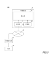
- FIG. 3 is a block diagram illustrating a configuration of an information management system according to an embodiment of the present disclosure.
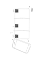
- FIG. 4 is a diagram showing an example of a method for reading the position information stored in the code shown in FIG.
- FIG. 5 is a sequence diagram for explaining the flow of operations of the information management system shown in FIG.
- the present disclosure aims to provide an information management system and information management method that can more accurately obtain the recommended length of a cable to be laid in a duct.
- the recommended length of a cable to be installed in a duct can be obtained more accurately.
- the information management system includes: (1) An information management system for calculating the length of a duct in which a cable is laid, comprising: a first code is attached to a first end in a longitudinal direction of the duct, and first position information indicating a position of the first end is stored in the first code;
- the information management system includes: an acquisition unit that acquires the first position information after the duct is installed; A calculation unit calculates a length of the laid duct based on the first position information.
- the length of the duct after installation can be easily calculated. Furthermore, by obtaining the length of the duct after installation, for example, a worker can more accurately acquire the recommended length of the cable to be installed inside the duct.
- a second code is attached to a second end, which is an end of the duct opposite to the first end in a longitudinal direction thereof, and second position information indicating a position of the second end is stored in the second code;
- the acquisition unit acquires the first position information and the second position information after the duct is installed,
- the calculation unit may calculate a length of the laid duct based on the first position information and the second position information.
- This configuration eliminates the need to check the positions of the duct ends in advance, and makes it easy to obtain position information for both ends of the duct after installation.
- the calculation unit may further calculate a recommended length of a cable to be laid inside the duct based on the calculated length of the duct.
- the recommended length of the cable to be laid is automatically calculated, reducing the burden on the worker in determining the recommended length of the cable.
- a connector may be attached to an end of a cable to be laid in the duct before the cable is laid in the duct.
- the first code further stores diameter information indicating a diameter of the duct
- the calculation unit may further calculate a recommended diameter of a cable to be laid inside the duct based on the diameter information.
- This configuration allows workers to prepare a more suitable cable to be laid inside the duct.
- An information management method includes: (6) An information management method for calculating a length of a duct in which a cable is laid, comprising the steps of: a first code is attached to a first end in a longitudinal direction of the duct, and first position information indicating a position of the first end is stored in the first code; acquiring the first position information after laying the duct; and calculating a length of the laid duct based on the first position information.
- the length of the duct after installation can be easily calculated. Furthermore, by obtaining the length of the duct after installation, for example, a worker can more accurately obtain the recommended length of the cable to be installed inside the duct.
- Fig. 1 is a perspective view showing an example of a cable 1, a subduct 2, and a main duct 3 in which an information management system 100 according to an embodiment of the present disclosure is used.
- a subduct 2 is laid inside the main duct 3, and a cable 1 is laid inside the subduct 2.
- one cable 1 is laid inside one subduct 2 in Fig. 1, multiple cables 1 may be laid inside one subduct 2.
- Cable 1 is, for example, a microduct cable that is laid inside subduct 2 by air pressure or towing, and has an outer diameter of about 20 mm.
- Cable 1 is, for example, an optical fiber cable, and includes a cable core 11 and an outer sheath 12 formed around cable core 11.
- FIG. 2 is a diagram showing an example of a state in which a connector 5 is attached to the end of the cable 1 shown in FIG. 1.
- the cable 1 has a connector 5 attached to its end before being laid inside the subduct 2.
- the connector 5 is, for example, a multi-core connector, and has a plurality of ferrules 51. Each ferrule 51 is connected to an end of an optical fiber core 13 (see FIG. 1) in the optical fiber ribbon 16.
- a protective tube 4 is provided at the end of the cable 1, and the connector 5 is housed inside the protective tube 4.
- the cable core 11 includes an optical fiber ribbon 16 including a plurality of optical fiber cores 13, and an upper winding tape 14 that covers the periphery of the plurality of optical fiber ribbons 16.
- the optical fiber cores 13 that make up the optical fiber ribbon 16 may be, for example, such that adjacent optical fiber cores 13 are intermittently connected along the longitudinal direction of the cable 1.
- the cable 1 shown in FIG. 1 is a slotless type, it may also be a slot type.
- the top winding tape 14 is wrapped around the multiple optical fiber ribbons 16 either vertically or horizontally.
- the outer jacket 12 is made of a resin such as high density polyethylene (HDPE) and is formed by extrusion molding around the top winding tape 14.
- the outer jacket 12 is preferably made of a material with a silicone additive content in the range of 0.1% to 0.5% by mass. In this case, when the cable 1 is laid inside the subduct 2, the outer jackets 12 can be made slippery when they are in contact with each other or with the subduct 2, making it easier to lay the cable 1.
- a code 31 is attached to the main duct 3.
- a QR code registered trademark
- a QR code registered trademark
- the code 31 stores location information of the location to which the code 31 is attached.
- the location information indicates the distance from a reference point in the main duct 3.
- the code 31 may also store at least one of the installation-related information such as the inner diameter, total length, bending angle, and inclination of the main duct 3.
- the code 31 may be printed by an inkjet printer or the like, or may be engraved with a laser. Also, instead of printing or engraving the code 31 directly on the main duct 3, a piece of paper with the code 31 printed on it or an IC chip or the like may be attached to the main duct 3. It is preferable that the code 31 is colored a different color from the color of the main duct 3. This makes it easy to see where the code 31 is attached.
- the code 31 is not limited to being attached to the main duct 3, but may be attached to the sub-duct 2.
- position information indicating the distance from a reference point on the sub-duct 2 is stored in the code 31.
- FIG. 3 is a block diagram showing a configuration of an information management system 100 according to an embodiment of the present disclosure.
- the information management system 100 includes a terminal (acquisition unit) 10 and a management device 20.
- the terminal 10 and the management device 20 are communicatively connected via an external network 40 such as the Internet and a wireless base station 41.
- the terminal 10 is, for example, a smartphone used by a worker who installs the cable 1, and includes an imaging function and a display function.
- Fig. 4 is a diagram showing an example of a method for reading the position information stored in the code 31 shown in Fig. 1.
- the main duct 3 is provided with the codes 31 at a plurality of positions at predetermined intervals along the longitudinal direction of the main duct 3.
- the predetermined intervals are within a range of, for example, 30 cm to 1 m.
- the worker uses the terminal 10 to capture an image of the cord 31 (hereinafter referred to as the "first cord 31A") attached to the first end 3A in the longitudinal direction of the main duct 3 after installation.
- the terminal 10 acquires first position information, which is position information of the first end 3A.
- the first end 3A of the main duct 3 includes the vicinity of the first end 3A.
- the worker also uses the terminal 10 to capture an image of the cord 31 (hereinafter referred to as the "second cord 31B") attached to the second end 3B of the main duct 3 opposite the first end 3A in the longitudinal direction after installation.
- the terminal 10 acquires second position information, which is position information of the second end 3B.
- the terminal 10 transmits the acquired first and second position information to the management device 20 via the wireless base station 41 and external network 40 shown in FIG. 3.
- the second end 3B of the main duct 3 includes the vicinity of the second end 3B.
- the management device 20 has a communication unit 21, a storage unit 22, and a calculation unit 23.
- the communication unit 21 receives the first location information and the second location information transmitted from the terminal 10, and outputs the first location information and the second location information to the calculation unit 23.
- the calculation unit 23 calculates the length of the installed main duct 3 (hereinafter referred to as "installed duct length") based on the first location information and the second location information.
- the calculation unit 23 further calculates a recommended length of the cable 1 to be laid inside the main duct 3 (hereinafter referred to as the "recommended cable length") based on the calculated laying duct length. More specifically, for example, a calculation formula indicating the correspondence between the laying duct length and the recommended cable length is stored in the memory unit 22. The calculation unit 23 uses the calculation formula to calculate, for example, a value obtained by adding a predetermined value to the laying duct length as the recommended cable length. The calculation unit 23 then outputs duct length information indicating the calculated laying duct length and cable length information indicating the recommended cable length to the communication unit 21.
- the communication unit 21 When the communication unit 21 receives the duct length information and cable length information from the calculation unit 23, it transmits the duct length information and cable length information to the terminal 10 via the external network 40 and the wireless base station 41.
- the terminal 10 receives the duct length information and cable length information transmitted from the management device 20, it displays the laid duct length indicated by the duct length information and the recommended cable length indicated by the cable length information on the screen of the terminal 10.
- the terminal 10 may acquire the installation-related information of the main duct 3 in addition to the position information of the place where the code 31 is attached by capturing an image of the code 31, and transmit the acquired information to the management device 20.
- the communication unit 21 in the management device 20 receives the position information and installation-related information transmitted from the terminal 10, it outputs the position information and installation-related information to the calculation unit 23.
- the calculation unit 23 calculates the installation duct length and the recommended cable length based on the position information from the terminal 10, and may further adjust the recommended cable length according to the inclination angle of the main duct 3 included in the installation-related information from the terminal 10. This makes it possible to obtain a more accurate recommended cable length.
- the installation-related information stored in the code 31 includes the total length of the main duct 3.
- the calculation unit 23 in the management device 20 may determine the installation duct length based on, for example, the location information and the information on the total length of the main duct 3 included in the installation-related information, and calculate the recommended cable length based on this installation duct length.
- diameter information indicating the inner diameter of the main duct 3 is stored in the code 31 as installation-related information.
- the calculation unit 23 in the management device 20 may calculate the recommended inner diameter of the cable 1 to be installed in the main duct 3 based on the diameter information transmitted from the terminal 10 in addition to the recommended cable length.
- the position information stored in code 31 is not limited to the distance from the reference point of main duct 3, i.e., the numerical value itself, but may be identification information corresponding to the distance. Identification information is, for example, a letter, code, or symbol corresponding to the distance from the reference point. Similarly, when installation-related information is stored in code 31, identification information corresponding to these values, i.e., letters, codes, or symbols, may be stored in code 31, not limited to the values of various parameters related to the installation of main duct 3 themselves.
- the memory unit 22 in the management device 20 stores a first correspondence table indicating the correspondence between the distance from the reference point of the main duct 3 and the identification information.
- the calculation unit 23 in the management device 20 receives the identification information instead of the first position information or the second position information, it can, for example, refer to the first correspondence table to obtain the distance corresponding to the identification information.
- the memory unit 22 also stores a second correspondence table that indicates the correspondence between various values included in the installation-related information of the main duct 3 and the identification information.
- the calculation unit 23 receives identification information as installation-related information, it can, for example, refer to the second correspondence table to obtain various values that correspond to the identification information.
- the distance from the reference point to the first end 3A or the distance from the reference point to the second end 3B may be known.
- the worker may use the terminal 10 to capture an image of only the code 31 attached to the end other than the end whose distance from the reference point is known. After reading one piece of location information stored in the code 31, the terminal 10 transmits the location information to the management device 20, for example, when it receives an operation by the worker to instruct the transmission of the location information.
- the management device 20 When the management device 20 receives one piece of location information from the terminal 10, it calculates the installed duct length based on the location information. For example, the calculation unit 23 in the management device 20 calculates the distance from the reference point indicated by the location information as the installed duct length.
- Fig. 5 is a sequence diagram for explaining the flow of operations of the information management system shown in Fig. 3.
- a worker who lays the cable 1 uses the terminal 10 to capture an image of the first code 31A attached to the first end 3A of the main duct 3.
- the terminal 10 acquires the first position information stored in the first code 31A (step S11).
- the worker uses the terminal 10 to capture an image of the second code 31B attached to the second end 3B of the main duct 3.
- the terminal 10 acquires, for example, the second position information stored in the second code 31B (step S12).
- the terminal 10 transmits the first location information and the second location information to the management device 20 (step S13).
- the management device 20 when the management device 20 receives the first location information and the second location information transmitted from the terminal 10, it calculates the installed duct length, which is the length of the main duct 3 after installation, based on the first location information and the second location information (step S14).
- the management device 20 calculates the recommended cable length of the cable 1 to be laid inside the main duct 3 based on the calculated laying duct length (step S15).
- the management device 20 transmits duct length information indicating the laying duct length and cable length information indicating the recommended cable length to the terminal 10 (step S16).
- the terminal 10 displays the installed duct length indicated by the duct length information and the recommended cable length indicated by the cable length information on the screen of the terminal 10 (step S17).
- the length of the main duct 3 after installation can be easily calculated. Furthermore, since the recommended length of the cable 1 to be laid inside the main duct 3 is automatically calculated based on the length of the main duct 3 after installation, the recommended length of the cable 1 can be acquired without requiring much effort from the worker.
- the recommended cable length of the cable 1 can be obtained before the cable 1 is laid, and therefore, for example, the length of the cable 1 can be adjusted to the recommended cable length before a connector is attached to the end of the cable 1.
- the terminal 10 is not limited to a smartphone, and may be AR (Argumented Reality) glasses or the like.
- a two-dimensional code or one-dimensional code other than a QR code may be attached as the code 31 to the main duct 3.
- the terminal 10 shown in FIG. 3 may also have the function of the calculation unit 23 in the management device 20.
- an application program installed on the terminal 10 may calculate the installation duct length and the recommended cable length based on the first location information and the second location information.
- the calculation unit 23 is not limited to a configuration that calculates both the laying duct length and the recommended cable length, and may be configured to calculate only the laying duct length, for example. In this case, only the laying duct length is displayed on the screen of the terminal 10. The worker can estimate the recommended cable length by checking the laying duct length displayed on the screen.
- a code may be attached not only to the main duct 3 but also to the cable 1.
- the code includes at least one of the installation-related information of the cable 1, such as the manufacturer, manufacturing year, control number, outer diameter, mass, friction coefficient, stiffness, number of optical fiber cores, allowable tension, allowable bending diameter, and operating temperature.
- the management device 20 can store the laying-related information of the cable 1 in association with the laying-related information of the main duct 3 in which the cable 1 is laid.
- the worker after laying the cable 1, the worker has the terminal 10 read both the code 31 attached to the main duct 3 and the code attached to the cable 1.
- the terminal 10 acquires both the installation-related information stored in the code 31 of the main duct 3 and the installation-related information stored in the code of the cable 1, and transmits this installation-related information to the management device 20.
- the communication unit 21 in the management device 20 receives the installation-related information for the main duct 3 and the installation-related information for the cable 1 sent from the terminal 10.
- the communication unit 21 then stores, in the memory unit 22, for example, the installation-related information for the cable 1, the installation-related information for the main duct 3, the date of receipt of these two pieces of installation-related information, and the identification information of the terminal 10 in association with each other. In this way, by storing information related to the installation collectively after the installation of the cable 1 is completed, it becomes possible to present useful information to workers when performing maintenance management, etc.
Landscapes
- Physics & Mathematics (AREA)
- General Physics & Mathematics (AREA)
- Optics & Photonics (AREA)
- Laying Of Electric Cables Or Lines Outside (AREA)
Abstract
Description
ケーブルが内部に敷設されるダクトの長さを算出する情報管理システムであって、
前記ダクトの長手方向における第1端には第1コードが付され、前記第1コードには前記第1端の位置を示す第1位置情報が格納され、
前記情報管理システムは、
前記ダクトの敷設後に前記第1位置情報を取得する取得部と、
前記第1位置情報に基づいて、敷設された前記ダクトの長さを算出する算出部と、を備える。
ケーブルが内部に敷設されるダクトの長さを算出する情報管理方法であって、
前記ダクトの長手方向における第1端には第1コードが付され、前記第1コードには前記第1端の位置を示す第1位置情報が格納され、
前記ダクトの敷設後に前記第1位置情報を取得するステップと、
前記第1位置情報に基づいて、敷設された前記ダクトの長さを算出するステップと、を含む。
ところで、作業者は、敷設するケーブルの長さを決定する際、例えば、当該ケーブルを内部に敷設するダクトの地図上のルートを参照していた。しかしながら、地図上のルートに基づいて決定されるケーブルの長さと、実際にケーブルを敷設するダクトの長さとの間にはズレが生じる可能性があり、敷設するケーブル長が足りなくなったり、逆に余長が生じたりする可能性があった。このため、実際にケーブルを敷設するダクトの長さをより正確に取得することのできる技術が望まれている。
本開示によれば、ダクトに敷設されるケーブルの推奨される長さをより正確に取得することができる。
最初に本開示の実施形態を列記して説明する。
本開示の実施形態に係る情報管理システムは、
(1)ケーブルが内部に敷設されるダクトの長さを算出する情報管理システムであって、
前記ダクトの長手方向における第1端には第1コードが付され、前記第1コードには前記第1端の位置を示す第1位置情報が格納され、
前記情報管理システムは、
前記ダクトの敷設後に前記第1位置情報を取得する取得部と、
前記第1位置情報に基づいて、敷設された前記ダクトの長さを算出する算出部と、を備える。
前記ダクトの長手方向における前記第1端とは反対側の端である第2端に第2コードが付され、前記第2コードには前記第2端の位置を示す第2位置情報が格納され、
前記取得部は、前記ダクトの敷設後に前記第1位置情報および前記第2位置情報を取得し、
前記算出部は、前記第1位置情報および前記第2位置情報に基づいて、敷設された前記ダクトの長さを算出してもよい。
前記算出部は、さらに、算出した前記ダクトの長さに基づいて、前記ダクトの内部に敷設されるケーブルの推奨される長さを算出してもよい。
前記ダクトに敷設されるケーブルは、前記ダクトへの敷設前において、端部にコネクタが取り付けられていてもよい。
前記第1コードには、さらに、前記ダクトの径を示す径情報が格納され、
前記算出部は、さらに、前記径情報に基づいて、前記ダクトの内部に敷設されるケーブルの推奨される径を算出してもよい。
(6)ケーブルが内部に敷設されるダクトの長さを算出する情報管理方法であって、
前記ダクトの長手方向における第1端には第1コードが付され、前記第1コードには前記第1端の位置を示す第1位置情報が格納され、
前記ダクトの敷設後に前記第1位置情報を取得するステップと、
前記第1位置情報に基づいて、敷設された前記ダクトの長さを算出するステップと、を含む。
本開示の情報管理システムの具体例を、以下に図面を参照しつつ説明する。なお、本開示はこれらの例示に限定されるものではなく、請求の範囲によって示され、請求の範囲と均等の意味および範囲内でのすべての変更が含まれることが意図される。
図1は、本開示の実施形態に係る情報管理システム100が用いられるケーブル1、サブダクト2およびメインダクト3の一例を示す斜視図である。図1に示すように、メインダクト3の内部にサブダクト2が敷設され、さらに、サブダクト2の内部にケーブル1が敷設される。図1では1つのサブダクト2の内部に1つのケーブル1が敷設されているが、1つのサブダクト2の内部に複数のケーブル1が敷設されてもよい。
図3は、本開示の実施形態に係る情報管理システム100の構成を示すブロック図である。図3を参照して、情報管理システム100は、端末(取得部)10と、管理装置20とを備える。端末10と管理装置20とは、インターネットなどの外部ネットワーク40、および無線基地局41を介して通信可能に接続されている。端末10は、例えば、ケーブル1の敷設を行う作業者が使用するスマートフォンなどであり、撮像機能および表示機能を備える。
図4は、図1に示すコード31に格納された位置情報の読み取り方法の一例を示す図である。図4に示すように、メインダクト3には、メインダクト3の長手方向に沿って、所定の間隔をあけて複数箇所にコード31が付されている。所定の間隔は、例えば、30cmから1mの範囲に含まれる。
再び図3を参照して、管理装置20は、通信部21と、記憶部22と、算出部23とを有する。通信部21は、端末10から送信された第1位置情報および第2位置情報を受信し、これら第1位置情報および第2位置情報を算出部23へ出力する。算出部23は、第1位置情報および第2位置情報に基づいて、敷設されたメインダクト3の長さ(以下、「敷設ダクト長」と称する)を算出する。
次に、本開示の実施形態に係る情報管理システムの動作の流れについて説明する。図5は、図3に示す情報管理システムの動作の流れを説明するためのシーケンス図である。図5を参照して、まず、ケーブル1の敷設を行う作業者は、メインダクト3の敷設後において、メインダクト3の第1端3Aに付された第1コード31Aを端末10によって撮像する。これにより、端末10は、第1コード31Aに格納されている第1位置情報を取得する(ステップS11)。
再び図1を参照して、本開示の実施形態に係る情報管理システム100は、メインダクト3だけでなく、ケーブル1においてもコードが付されていてもよい。当該コードには、ケーブル1の、製造会社、製造年、管理番号、外径、質量、摩擦係数、剛性、光ファイバ心線数、許容張力、許容曲げ径および使用温度などの敷設関連情報のうちの少なくとも1つが含まれる。
2 サブダクト
3 メインダクト
3A 第1端
3B 第2端
4 保護管
5 コネクタ
10 端末(取得部)
11 ケーブルコア
12 外被
13 光ファイバ心線
14 テープ
16 光ファイバリボン
20 管理装置
21 通信部
22 記憶部
23 算出部
31 コード
31A 第1コード
31B 第2コード
40 外部ネットワーク
41 無線基地局
51 フェルール
100 情報管理システム
Claims (6)
- ケーブルが内部に敷設されるダクトの長さを算出する情報管理システムであって、
前記ダクトの長手方向における第1端には第1コードが付され、前記第1コードには前記第1端の位置を示す第1位置情報が格納され、
前記情報管理システムは、
前記ダクトの敷設後に前記第1位置情報を取得する取得部と、
前記第1位置情報に基づいて、敷設された前記ダクトの長さを算出する算出部と、を備える、情報管理システム。 - 前記ダクトの長手方向における前記第1端とは反対側の端である第2端に第2コードが付され、前記第2コードには前記第2端の位置を示す第2位置情報が格納され、
前記取得部は、前記ダクトの敷設後に前記第1位置情報および前記第2位置情報を取得し、
前記算出部は、前記第1位置情報および前記第2位置情報に基づいて、敷設された前記ダクトの長さを算出する、請求項1に記載の情報管理システム。 - 前記算出部は、さらに、算出した前記ダクトの長さに基づいて、前記ダクトの内部に敷設されるケーブルの推奨される長さを算出する、請求項1に記載の情報管理システム。
- 前記ダクトに敷設されるケーブルは、前記ダクトへの敷設前において、端部にコネクタが取り付けられている、請求項1に記載の情報管理システム。
- 前記第1コードには、さらに、前記ダクトの径を示す径情報が格納され、
前記算出部は、さらに、前記径情報に基づいて、前記ダクトの内部に敷設されるケーブルの推奨される径を算出する、請求項1に記載の情報管理システム。 - ケーブルが内部に敷設されるダクトの長さを算出する情報管理方法あって、
前記ダクトの長手方向における第1端には第1コードが付され、前記第1コードには前記第1端の位置を示す第1位置情報が格納され、
前記ダクトの敷設後に前記第1位置情報を取得するステップと、
前記第1位置情報に基づいて、敷設された前記ダクトの長さを算出するステップと、を含む、情報管理方法。
Priority Applications (4)
| Application Number | Priority Date | Filing Date | Title |
|---|---|---|---|
| JP2025532320A JPWO2025013240A1 (ja) | 2023-07-12 | 2023-07-12 | |
| PCT/JP2023/025724 WO2025013240A1 (ja) | 2023-07-12 | 2023-07-12 | 情報管理システムおよび情報管理方法 |
| EP23945115.6A EP4745645A1 (en) | 2023-07-12 | 2023-07-12 | INFORMATION MANAGEMENT SYSTEM AND INFORMATION MANAGEMENT PROCESS |
| US19/381,365 US20260066631A1 (en) | 2023-07-12 | 2025-11-06 | Information management system and information management method |
Applications Claiming Priority (1)
| Application Number | Priority Date | Filing Date | Title |
|---|---|---|---|
| PCT/JP2023/025724 WO2025013240A1 (ja) | 2023-07-12 | 2023-07-12 | 情報管理システムおよび情報管理方法 |
Related Child Applications (1)
| Application Number | Title | Priority Date | Filing Date |
|---|---|---|---|
| US19/381,365 Continuation-In-Part US20260066631A1 (en) | 2023-07-12 | 2025-11-06 | Information management system and information management method |
Publications (1)
| Publication Number | Publication Date |
|---|---|
| WO2025013240A1 true WO2025013240A1 (ja) | 2025-01-16 |
Family
ID=94214795
Family Applications (1)
| Application Number | Title | Priority Date | Filing Date |
|---|---|---|---|
| PCT/JP2023/025724 Ceased WO2025013240A1 (ja) | 2023-07-12 | 2023-07-12 | 情報管理システムおよび情報管理方法 |
Country Status (4)
| Country | Link |
|---|---|
| US (1) | US20260066631A1 (ja) |
| EP (1) | EP4745645A1 (ja) |
| JP (1) | JPWO2025013240A1 (ja) |
| WO (1) | WO2025013240A1 (ja) |
Families Citing this family (1)
| Publication number | Priority date | Publication date | Assignee | Title |
|---|---|---|---|---|
| JP2025011962A (ja) * | 2023-07-12 | 2025-01-24 | 住友電気工業株式会社 | 情報管理システムおよび情報管理方法 |
Citations (7)
| Publication number | Priority date | Publication date | Assignee | Title |
|---|---|---|---|---|
| US4508317A (en) * | 1982-02-05 | 1985-04-02 | Conti Allen C | Tape and method for measuring and/or pulling cable |
| JPH062934U (ja) * | 1992-06-03 | 1994-01-14 | 日本電信電話株式会社 | 管路長計尺装置 |
| JP2001021730A (ja) | 1999-07-07 | 2001-01-26 | Showa Electric Wire & Cable Co Ltd | 光ケーブルの布設関連情報管理方法 |
| JP2002366616A (ja) * | 2001-06-08 | 2002-12-20 | Hakko Co Ltd | マンホール情報の管理方法及び管理システム |
| JP2003153410A (ja) * | 2001-11-08 | 2003-05-23 | Furukawa Electric Co Ltd:The | 地中箱および該地中箱に設置される標識付き管路口形成部材 |
| KR20150030043A (ko) * | 2013-09-11 | 2015-03-19 | 삼성중공업 주식회사 | 케이블 포설 시스템 |
| CN211348754U (zh) * | 2019-08-29 | 2020-08-25 | 新能量科技股份有限公司 | 一种带二维码的户外光缆安装封堵装置 |
-
2023
- 2023-07-12 JP JP2025532320A patent/JPWO2025013240A1/ja active Pending
- 2023-07-12 WO PCT/JP2023/025724 patent/WO2025013240A1/ja not_active Ceased
- 2023-07-12 EP EP23945115.6A patent/EP4745645A1/en active Pending
-
2025
- 2025-11-06 US US19/381,365 patent/US20260066631A1/en active Pending
Patent Citations (7)
| Publication number | Priority date | Publication date | Assignee | Title |
|---|---|---|---|---|
| US4508317A (en) * | 1982-02-05 | 1985-04-02 | Conti Allen C | Tape and method for measuring and/or pulling cable |
| JPH062934U (ja) * | 1992-06-03 | 1994-01-14 | 日本電信電話株式会社 | 管路長計尺装置 |
| JP2001021730A (ja) | 1999-07-07 | 2001-01-26 | Showa Electric Wire & Cable Co Ltd | 光ケーブルの布設関連情報管理方法 |
| JP2002366616A (ja) * | 2001-06-08 | 2002-12-20 | Hakko Co Ltd | マンホール情報の管理方法及び管理システム |
| JP2003153410A (ja) * | 2001-11-08 | 2003-05-23 | Furukawa Electric Co Ltd:The | 地中箱および該地中箱に設置される標識付き管路口形成部材 |
| KR20150030043A (ko) * | 2013-09-11 | 2015-03-19 | 삼성중공업 주식회사 | 케이블 포설 시스템 |
| CN211348754U (zh) * | 2019-08-29 | 2020-08-25 | 新能量科技股份有限公司 | 一种带二维码的户外光缆安装封堵装置 |
Also Published As
| Publication number | Publication date |
|---|---|
| EP4745645A1 (en) | 2026-05-20 |
| JPWO2025013240A1 (ja) | 2025-01-16 |
| US20260066631A1 (en) | 2026-03-05 |
Similar Documents
| Publication | Publication Date | Title |
|---|---|---|
| US6661956B2 (en) | Optical fiber cable for use in a dispersion managed cable system | |
| US7203404B2 (en) | Loose tube fiber optic cables having at least one access location | |
| US6823120B2 (en) | Transmit/receive optical cables | |
| US7242841B2 (en) | Cross-connect fiber optic cables and associated cross-connect sections | |
| CN114008503B (zh) | 间歇连结型光纤带、及间歇连结型光纤带的制造方法 | |
| JP2019124936A (ja) | 間欠接着型光ファイバーリボンを組み込んだ多心ユニットチューブ光ファイバーマイクロケーブル | |
| US20260066631A1 (en) | Information management system and information management method | |
| WO2020045372A1 (ja) | 識別マーク付光ファイバ心線、識別マーク付光ファイバ心線の製造方法 | |
| US7190866B2 (en) | Distribution fiber optic cables having at least one access location and methods of making the same | |
| EP3798704A1 (en) | Method of preparing a bundled cable, and a bundled optical fiber cable | |
| JP2006127896A (ja) | ケーブル及びケーブル管理システム | |
| US20250164733A1 (en) | Optical fiber cable, optical fiber ribbon, method of installing optical fiber cable, and optical transmission system | |
| JP2022187862A (ja) | 光ファイバ集合体の製造方法、光ファイバ集合体、及び、光ファイバ集合体の接続方法 | |
| JP2025011962A (ja) | 情報管理システムおよび情報管理方法 | |
| US7668425B1 (en) | Bi-directional cable assembly with bend-improved fiber tether | |
| US20030016923A1 (en) | Dispersion managed fiber optic cable system with bridging path and marking methods therefor | |
| Borzycki et al. | Accurate location of fiber cable fault with otdr | |
| EP1223449B1 (en) | Apparatus and method for on-line binder laylength measurement and adjustment | |
| WO2024134733A1 (ja) | 光ファイバケーブル、および光ファイバケーブルの情報管理方法 | |
| WO2024257260A1 (ja) | 光ケーブルの再利用システム | |
| WO2024134732A1 (ja) | ケーブル、ケーブルの情報管理システムおよびケーブルの情報管理方法 | |
| JP7583847B2 (ja) | ファイバ集合体 | |
| KR102245214B1 (ko) | 광섬유 격자 센서의 제조 방법 | |
| JP2021111507A (ja) | 長尺体の曲がり表示装置、長尺体、および長尺体の敷設方法 | |
| JP2009086176A (ja) | 光ケーブルユニット及び集合光ケーブル並びに光ケーブルユニットの検出方法 |
Legal Events
| Date | Code | Title | Description |
|---|---|---|---|
| 121 | Ep: the epo has been informed by wipo that ep was designated in this application |
Ref document number: 23945115 Country of ref document: EP Kind code of ref document: A1 |
|
| ENP | Entry into the national phase |
Ref document number: 2025532320 Country of ref document: JP Kind code of ref document: A |
|
| WWE | Wipo information: entry into national phase |
Ref document number: 2025532320 Country of ref document: JP |
|
| WWE | Wipo information: entry into national phase |
Ref document number: 2023945115 Country of ref document: EP |
|
| NENP | Non-entry into the national phase |
Ref country code: DE |
|
| WWP | Wipo information: published in national office |
Ref document number: 2023945115 Country of ref document: EP |