WO2025009541A1 - リードおよび非水電解質電池 - Google Patents
リードおよび非水電解質電池 Download PDFInfo
- Publication number
- WO2025009541A1 WO2025009541A1 PCT/JP2024/024004 JP2024024004W WO2025009541A1 WO 2025009541 A1 WO2025009541 A1 WO 2025009541A1 JP 2024024004 W JP2024024004 W JP 2024024004W WO 2025009541 A1 WO2025009541 A1 WO 2025009541A1
- Authority
- WO
- WIPO (PCT)
- Prior art keywords
- layer
- insulating film
- conductor
- lead
- peak temperature
- Prior art date
- Legal status (The legal status is an assumption and is not a legal conclusion. Google has not performed a legal analysis and makes no representation as to the accuracy of the status listed.)
- Ceased
Links
Images


Classifications
-
- H—ELECTRICITY
- H01—ELECTRIC ELEMENTS
- H01M—PROCESSES OR MEANS, e.g. BATTERIES, FOR THE DIRECT CONVERSION OF CHEMICAL ENERGY INTO ELECTRICAL ENERGY
- H01M50/00—Constructional details or processes of manufacture of the non-active parts of electrochemical cells other than fuel cells, e.g. hybrid cells
- H01M50/50—Current conducting connections for cells or batteries
- H01M50/531—Electrode connections inside a battery casing
- H01M50/534—Electrode connections inside a battery casing characterised by the material of the leads or tabs
-
- H—ELECTRICITY
- H01—ELECTRIC ELEMENTS
- H01M—PROCESSES OR MEANS, e.g. BATTERIES, FOR THE DIRECT CONVERSION OF CHEMICAL ENERGY INTO ELECTRICAL ENERGY
- H01M50/00—Constructional details or processes of manufacture of the non-active parts of electrochemical cells other than fuel cells, e.g. hybrid cells
- H01M50/10—Primary casings; Jackets or wrappings
- H01M50/102—Primary casings; Jackets or wrappings characterised by their shape or physical structure
- H01M50/105—Pouches or flexible bags
-
- H—ELECTRICITY
- H01—ELECTRIC ELEMENTS
- H01M—PROCESSES OR MEANS, e.g. BATTERIES, FOR THE DIRECT CONVERSION OF CHEMICAL ENERGY INTO ELECTRICAL ENERGY
- H01M50/00—Constructional details or processes of manufacture of the non-active parts of electrochemical cells other than fuel cells, e.g. hybrid cells
- H01M50/10—Primary casings; Jackets or wrappings
- H01M50/116—Primary casings; Jackets or wrappings characterised by the material
- H01M50/124—Primary casings; Jackets or wrappings characterised by the material having a layered structure
- H01M50/126—Primary casings; Jackets or wrappings characterised by the material having a layered structure comprising three or more layers
- H01M50/129—Primary casings; Jackets or wrappings characterised by the material having a layered structure comprising three or more layers with two or more layers of only organic material
-
- H—ELECTRICITY
- H01—ELECTRIC ELEMENTS
- H01M—PROCESSES OR MEANS, e.g. BATTERIES, FOR THE DIRECT CONVERSION OF CHEMICAL ENERGY INTO ELECTRICAL ENERGY
- H01M50/00—Constructional details or processes of manufacture of the non-active parts of electrochemical cells other than fuel cells, e.g. hybrid cells
- H01M50/10—Primary casings; Jackets or wrappings
- H01M50/172—Arrangements of electric connectors penetrating the casing
- H01M50/174—Arrangements of electric connectors penetrating the casing adapted for the shape of the cells
- H01M50/178—Arrangements of electric connectors penetrating the casing adapted for the shape of the cells for pouch or flexible bag cells
-
- H—ELECTRICITY
- H01—ELECTRIC ELEMENTS
- H01M—PROCESSES OR MEANS, e.g. BATTERIES, FOR THE DIRECT CONVERSION OF CHEMICAL ENERGY INTO ELECTRICAL ENERGY
- H01M50/00—Constructional details or processes of manufacture of the non-active parts of electrochemical cells other than fuel cells, e.g. hybrid cells
- H01M50/10—Primary casings; Jackets or wrappings
- H01M50/183—Sealing members
- H01M50/19—Sealing members characterised by the material
- H01M50/193—Organic material
-
- H—ELECTRICITY
- H01—ELECTRIC ELEMENTS
- H01M—PROCESSES OR MEANS, e.g. BATTERIES, FOR THE DIRECT CONVERSION OF CHEMICAL ENERGY INTO ELECTRICAL ENERGY
- H01M50/00—Constructional details or processes of manufacture of the non-active parts of electrochemical cells other than fuel cells, e.g. hybrid cells
- H01M50/10—Primary casings; Jackets or wrappings
- H01M50/183—Sealing members
- H01M50/19—Sealing members characterised by the material
- H01M50/197—Sealing members characterised by the material having a layered structure
-
- Y—GENERAL TAGGING OF NEW TECHNOLOGICAL DEVELOPMENTS; GENERAL TAGGING OF CROSS-SECTIONAL TECHNOLOGIES SPANNING OVER SEVERAL SECTIONS OF THE IPC; TECHNICAL SUBJECTS COVERED BY FORMER USPC CROSS-REFERENCE ART COLLECTIONS [XRACs] AND DIGESTS
- Y02—TECHNOLOGIES OR APPLICATIONS FOR MITIGATION OR ADAPTATION AGAINST CLIMATE CHANGE
- Y02E—REDUCTION OF GREENHOUSE GAS [GHG] EMISSIONS, RELATED TO ENERGY GENERATION, TRANSMISSION OR DISTRIBUTION
- Y02E60/00—Enabling technologies; Technologies with a potential or indirect contribution to GHG emissions mitigation
- Y02E60/10—Energy storage using batteries
Definitions
- Patent Document 1 discloses a tab lead that uses an adhesive film for metal terminals that has at least one resin layer having a polyolefin skeleton in order to improve adhesion between the conductor and the sealed container.
- this adhesive film for metal terminals is measured with a differential scanning calorimeter, a melting peak is observed in the range of 120°C to 156°C.
- the lead of the present disclosure is a lead comprising a conductor and an insulating film covering at least a portion of the outer circumferential surface of the conductor, the insulating film having a plurality of layers including a first layer in contact with the surface of the conductor, the first layer being an acid-modified polyolefin layer, the difference between the melting peak temperature obtained by heating the first layer from 0°C to 250°C at 10°C/min using a differential scanning calorimeter and the crystallization peak temperature obtained by cooling the first layer from 250°C to 0°C at -10°C/min after heating is 34°C or less, and the melting peak temperature and the crystallization peak temperature are each 80°C or more and 170°C or less.
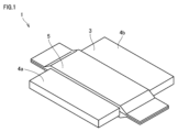
- FIG. 1 is a perspective view of a lead according to one embodiment of the present disclosure.
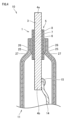
- FIG. 2 is a partial cross-sectional view of a lead according to one embodiment of the present disclosure.
- FIG. 3 is a perspective view illustrating an example of a nonaqueous electrolyte battery including a lead according to an embodiment of the present disclosure.
- FIG. 4 is a vertical cross-sectional view of the nonaqueous electrolyte battery of FIG.
- the objective of this disclosure is to provide a lead that has excellent adhesion between the insulating film and the conductor even when in contact with an electrolyte, and a nonaqueous electrolyte battery that includes the lead.
- the present disclosure it is possible to provide a lead that has excellent adhesion between the insulating film and the conductor even when in contact with an electrolyte, and a nonaqueous electrolyte battery that includes the lead.
- a lead according to the present disclosure includes a conductor and an insulating film covering at least a portion of an outer peripheral surface of the conductor, the insulating film having a plurality of layers including a first layer in contact with a surface of the conductor, the first layer being an acid-modified polyolefin layer, the difference between a melting peak temperature obtained by heating the first layer from 0°C to 250°C at a rate of 10°C/min using a differential scanning calorimeter and a crystallization peak temperature obtained by cooling the first layer from 250°C to 0°C at a rate of -10°C/min after the heating is 34°C or less, and the melting peak temperature and the crystallization peak temperature are each 80°C or more and 170°C or less.
- the present disclosure it is possible to provide a lead that has excellent adhesion between the insulating film and the conductor even when in contact with an electrolyte, and a nonaqueous electrolyte battery that includes the lead.
- the crystallization peak temperature may be 100°C or higher and 120°C or lower. This further improves the adhesive strength between the insulating film and the conductor.
- the first layer may contain a crystal nucleating agent. This further improves the adhesive strength between the insulating film and the conductor.
- the crystal nucleating agent may contain at least one selected from the group consisting of sorbitol-based nucleating agents, nonitol-based nucleating agents, amide-based nucleating agents, aromatic carboxylate metal salt-based nucleating agents, phosphate ester metal salt-based nucleating agents, and talc. This further improves the adhesive strength between the insulating film and the conductor.
- the storage modulus of the first layer at 25°C may be 1000 MPa or more and 1400 MPa or less.
- the loss modulus of the first layer at 25°C may be 70 MPa or more and 120 MPa or less.
- the nonaqueous electrolyte battery disclosed herein is a nonaqueous electrolyte battery comprising an enclosed container and a plurality of leads described in any one of (1) to (6) above that are arranged to extend from the inside to the outside of the enclosed container, the enclosed container being formed from a sheet body in which an innermost resin layer, a metal layer, and an outermost resin layer are laminated in the aforementioned order, and the innermost resin layer and the insulating film are fused together.
- This disclosure makes it possible to provide a nonaqueous electrolyte battery that includes leads that have excellent adhesion between the insulating film and the conductor, even when in contact with an electrolyte.
- any one numerical value listed as the lower limit and any one numerical value listed as the upper limit is also considered to be disclosed.
- a1, b1, and c1 are listed as the lower limit and a2, b2, and c2 are listed as the upper limit
- a1 to a2, a1 to b2, a1 to c2, b1 to a2, b1 to b2, b1 to c2, c1 to a2, c1 to b2, and c1 to c2 are considered to be disclosed.
- FIG. 1 is a perspective view of a lead 1 according to an embodiment of the present disclosure (hereinafter also referred to as "embodiment 1").
- FIG. 2 is a partial cross-sectional view of the lead 1 according to the embodiment of the present disclosure.
- the lead 1 according to the embodiment of the present disclosure includes a conductor 3 and an insulating film 5 covering at least a part of the outer circumferential surface of the conductor 3.
- the insulating film 5 has a plurality of layers including a first layer 6 in contact with the surface of the conductor 3. As shown in FIG.
- the insulating film 5 may have, in order from the first layer 6 in contact with the surface of the conductor 3, a second layer 7 in contact with the surface of the first layer 6 and a third layer 8 in contact with the surface of the second layer 7.
- the conductor 3 corresponds to a lead conductor.
- Insulating film 5 is shown in FIG. 2 as having a three-layer structure including first layer 6, second layer 7, and third layer 8, but the number of layers included in insulating film 5 is not limited to three. Insulating film 5 may also have a two-layer structure including first layer 6 and second layer 7. In addition to first layer 6, second layer 7, and third layer 8, insulating film 5 may also include other layers.
- the conductor 3 is connected to the electrodes of the nonaqueous electrolyte battery, etc.
- materials for the conductor 3 include metal materials such as aluminum, titanium, nickel, copper, aluminum alloys, titanium alloys, nickel alloys, copper alloys, etc., and materials obtained by plating these metal materials with nickel, gold, etc.
- the conductor 3 may be subjected to a surface treatment to prevent corrosion by the electrolyte.
- the average thickness of the conductor 3 is 0.10 mm or more, sufficient current can be passed through the conductor 3 for practical use as a battery.
- the average thickness of the conductor 3 may be 0.5 mm or more. In this case, a particularly large current can be passed through the conductor 3.
- an upper limit of the average thickness of the conductor 3 of 3 mm is sufficient.
- the average thickness of the conductor 3 is the average value of the thickness measurements at five points on a cross section along the normal direction of the conductor's main surface.
- the insulating film 5 is used as an insulating film for the lead 1.
- the insulating film 5 has a plurality of layers, and is provided on the outer peripheral surface of the conductor 3 so as to cover at least a part of the outer peripheral surface of the conductor 3.
- the insulating film 5 can be used to fill the space between the conductor 3 and the sealed container 11 without creating any gaps.
- the upper limit of the average thickness of the insulating film 5 is 0.30 mm.
- the average thickness of the insulating film 5 is measured by the following procedure.
- the insulating film 5 is cut with a microtome or the like along the normal direction of the surface with the largest area among the outer peripheral surfaces of the insulating film 5 to expose the cross section.
- the cross section is observed at 250x magnification using a digital microscope, and the thickness of the insulating film 5 is measured at five locations.
- the average of the thicknesses at the five locations is calculated. This average corresponds to the average thickness of the insulating film 5.
- the average thicknesses of the first layer 6, second layer 7, and third layer 8 described below are also measured in the same manner.
- the first layer 6 is an acid-modified polyolefin layer.
- the first layer 6 has good adhesion to a conductor and can fully exhibit adhesion to the second layer 7.
- Acid-modified polyolefins are polyolefins that contain acid-modified groups and are modified with carboxylic acids such as maleic acid, acrylic acid, methacrylic acid, and maleic anhydride.
- the acid-modified polyolefin may be acid-modified polypropylene.
- Examples of acid-modified polyolefins include maleic acid-modified polypropylene, acrylic acid-modified polypropylene, maleic anhydride-modified polypropylene, acrylic acid-modified polyethylene, maleic anhydride-modified polyethylene, and acrylic acid-modified ethylene acrylate.
- the first layer 6 may be an acid-modified polypropylene layer. This provides the first layer 6 with excellent adhesion and sealing properties to metals.
- the first layer 6 may be a maleic anhydride-modified polypropylene layer. This provides the first layer 6 with extremely excellent adhesion and sealing properties to metals.
- the first layer 6 may contain unmodified polyolefin as well as acid-modified polyolefin as a resin component, as long as the effect of the present disclosure is not impaired.
- acid-modified polyolefin and unmodified polyolefin will be collectively referred to as polyolefin.
- the fact that the first layer 6 contains acid-modified groups can be confirmed by performing a transmission light analysis on the insulating film 5 using a Fourier transform infrared spectrophotometer (FT-IR).
- FT-IR Fourier transform infrared spectrophotometer
- the content of acid-modified polyolefin in the first layer 6 may be 3% by mass or more. In terms of adhesion to the conductor, the content of acid-modified polyolefin may be higher. In terms of sufficient adhesion to the conductor, the acid-modified polyolefin may be contained at 60% by mass or more.
- the acid-modified polyolefin layer may contain a rubber component.
- the acid-modified polyolefin layer may contain at least one selected from the group consisting of ethylene propylene rubber, ethylene butene rubber, ethylene octene rubber, and propylene butene rubber.
- ethylene propylene rubber has excellent dispersibility in acid-modified polyolefins, especially acid-modified polypropylene.
- the adhesive strength between the insulating film 5 and the conductor is further improved.
- the first layer 6 of embodiment 1 may contain one or more of a crystal nucleating agent, an antioxidant, a flame retardant, a tackifier, a lubricant, a filler, a crystallization promoter, and a colorant, as long as the effect of the present disclosure is not impaired.
- the difference Tm-Tc between the melting peak temperature Tm [°C] obtained by heating the first layer 6 from 0°C to 250°C at 10°C/min using a differential scanning calorimeter and the crystallization peak temperature Tc [°C] obtained by cooling the first layer 6 from 250°C to 0°C at -10°C/min after heating is 34°C or less.
- the melting peak temperature Tm and the crystallization peak temperature Tc are each 80°C or more and 170°C or less.
- the temperature of the melting peak with the largest peak height is taken as the melting peak temperature Tm.
- the temperature of the crystallization peak with the largest peak height is taken as the crystallization peak temperature Tc.
- the difference Tm-Tc between the melting peak temperature Tm and the crystallization peak temperature Tc is 34°C or less from the viewpoint of improving the adhesive strength between the insulating film 5 and the conductor 3. Since the first layer is polyolefin, the difference Tm-Tc is 25°C or more.
- the melting peak temperature Tm may be 130°C or higher.
- the melting peak temperature Tm may be 170°C or lower.
- the crystallization peak temperature Tc may be 80°C or higher.
- the crystallization peak temperature Tc may be 130°C or lower.
- the first layer 6 may have a melting peak and a crystallization peak in the range of 80°C or more and 170°C or less, and may also have one or both of a melting peak and a crystallization peak outside the range of 80°C or more and 170°C or less.
- the half-width of the crystallization peak indicating the crystallization peak temperature Tc may be 5.0°C or more, 5.5°C or more, 6.0°C or more, 6.5°C or more, 6.6°C or more, 6.7°C or more, 6.8°C or more, 7.0°C or more, or 7.5°C or more.
- the upper limit of the half-width of the crystallization peak indicating the crystallization peak temperature Tc may be, for example, 10°C.
- the half-width is the full width at half maximum (FWHM).
- the melting peak temperature Tm, crystallization peak temperature Tc, and half-width of the crystallization peak of the first layer 6 are measured using a differential scanning calorimeter in accordance with JIS K 7121-1987 "Method for measuring transition temperature of plastics.” Specifically, the first layer 6 is removed from the insulating film 5, and the maximum melting peak temperature of 80°C to 170°C in the DSC (Differential Scanning Calorimetry) curve obtained by heating the first layer 6 from 0°C to 250°C at 10°C/min in a differential scanning calorimeter corresponds to the melting peak temperature Tm of the first layer.
- DSC Different Scanning Calorimetry
- the maximum crystallization peak temperature of 80°C to 170°C in the DSC curve obtained by heating the first layer 6 and then cooling it from 250°C to 0°C at -10°C/min corresponds to the crystallization peak temperature Tc of the first layer.
- the half-width of the peak indicating the crystallization peak temperature Tc corresponds to the half-width of the crystallization peak.
- the first layer 6 may contain a crystal nucleating agent.
- the crystal nucleating agent include organic crystal nucleating agents and inorganic crystal nucleating agents.
- the organic crystal nucleating agent include sorbitol-based nucleating agents, nonitol-based nucleating agents, amide-based nucleating agents, aromatic carboxylate metal salt-based nucleating agents, and phosphate metal salt-based nucleating agents.
- Sorbitol-based crystal nucleating agents include dibenzylidene sorbitol (DBS), monomethyl dibenzylidene sorbitol (e.g., 1,3:2,4-bis-O-(4-methylbenzylidene)-D-sorbitol), and dimethyl dibenzylidene sorbitol (e.g., 1,3:2,4-bis(3,4-dimethylbenzylidene)sorbitol (3,4-DMDBS)).
- DBS dibenzylidene sorbitol
- monomethyl dibenzylidene sorbitol e.g., 1,3:2,4-bis-O-(4-methylbenzylidene)-D-sorbitol
- dimethyl dibenzylidene sorbitol e.g., 1,3:2,4-bis(3,4-dimethylbenzylidene)sorbitol (3,4-DMDBS)
- nonitol-based crystal nucleating agents examples include 1,2,3-trideoxy-4,6:5,7-bis-[(4-propylphenyl)methylene]-nonitol.
- amide-based crystal nucleating agents examples include 1,3,5-tris(2,2-dimethylpropaneamino)benzene.
- aromatic carboxylate metal salt-based nucleating agents examples include sodium benzoate and calcium salt of 1,2-cyclohexanedicarboxylate.
- phosphate metal salt nucleating agents examples include sodium phosphate salts.
- An example of an inorganic crystal nucleating agent is talc.
- the crystal nucleating agent contained in the first layer 6 may include at least one selected from the group consisting of sorbitol-based nucleating agents, nonitol-based nucleating agents, amide-based nucleating agents, aromatic carboxylate metal salt-based nucleating agents, phosphate metal salt-based nucleating agents, and talc.
- the crystal nucleating agent contained in the first layer 6 may be a sorbitol-based crystal nucleating agent.
- the inclusion of the nucleating agent in the first layer 6 can be confirmed by the following procedure.
- the first layer 6 is removed from the insulating film 5 to prepare a sample.
- the sample formed from the first layer 6 is heated (e.g., to 120°C) and/or immersed (e.g., for 12 hours) in an organic solvent such as chloroform, N-methylpyrrolidone (NMP), or dimethyl sulfoxide (DMSO) to extract the nucleating agent, and then the freezing points of the sample before and after extraction are measured by DSC.
- NMP N-methylpyrrolidone
- DMSO dimethyl sulfoxide
- the freezing point temperature of the sample before the extraction of the nucleating agent is higher (e.g., by 4°C or more) than the freezing point temperature of the sample after the extraction of the nucleating agent, it is confirmed that the first phase 6 contains a nucleating agent.
- the content of the crystal nucleating agent can be adjusted as appropriate depending on the type of crystal nucleating agent.
- the lower limit of the mass percentage of the crystal nucleating agent relative to the total mass of the acid-modified polyolefin may be 0.30 mass%, 0.40 mass%, 0.50 mass%, 0.60 mass%, or 1.0 mass% from the viewpoint of improving the adhesive strength between the insulating film 5 and the conductor.
- the crystal nucleating agent may be dispersed in the film so as not to be observed as a foreign body, and the mass percentage of the crystal nucleating agent relative to the total mass of the acid-modified polyolefin may be, for example, 3.0 mass% or less.
- the mass percentage of the crystal nucleating agent relative to the total mass of the acid-modified polyolefin is measured by FT-IR or liquid chromatography.
- the storage modulus of the first layer 6 at 25° C. may be 1000 MPa or more and 1400 MPa or less from the viewpoint of making the insulating film less likely to deform.
- the loss modulus of the first layer 6 at 25°C may be 70 MPa or more and 120 MPa or less, from the viewpoint of preventing the insulating film from peeling off from the conductor.
- the storage modulus and loss modulus of the first layer 6 at 25°C are measured by the following procedure.
- a regular triangular pyramid indenter (Berkovich indenter) with a diamond tip is used in a nanoindenter.
- the insulating film 5 is cut along the normal direction of the main surface, which is the surface with the largest area among the outer peripheral surfaces of the insulating film 5, using a microtome or the like, and the cross section of the insulating film 5 is exposed by Ar ion milling.
- a nanoindenter (Bruker, Hysitron TI 980 Nanoindenter) is used to press the indenter perpendicularly to the cross section of the insulating film 5, and the storage modulus and loss modulus are calculated by dynamic viscoelasticity measurement.
- the dynamic viscoelasticity measurement is performed by adjusting the displacement amplitude to be 0.5 nm or more and 2 nm or less when the indenter is pressed with 8 mN, and the test is performed at a measurement frequency of 10 Hz and 25°C.
- the above measurements are performed at three locations, and the average of the storage modulus at the three locations and the average of the loss modulus at the three locations are calculated.
- the average of the storage modulus at the three locations corresponds to the storage modulus of the first layer 6.
- the average of the loss modulus at the three locations corresponds to the loss modulus of the first layer 6.
- the average thickness of the first layer 6 may be 10 ⁇ m or more. This allows the insulating film 5 to fill in the gap between the conductor and the sealed container 11 without creating a gap.
- the upper limit of the average thickness of the first layer 6 may be 150 ⁇ m. This reduces the amount of moisture that permeates the insulating film 5 from the atmosphere and enters the inside of the nonaqueous electrolyte battery.
- the insulating film 5 may include a second layer 7 that is in contact with the surface of the first layer 6 and is provided so as to sandwich the first layer 6 between the conductor 3.
- the second layer 7 is a heat-resistant resin layer.
- the second layer 7 functions as a support for the insulating film 5.
- the heat-resistant resin that forms the second layer 7 can be, for example, a cross-linked polyolefin or a polyolefin with a melting point 10°C or more higher than that of the first layer 6.
- the second layer 7 is unlikely to melt at the heat-sealing temperature when the opening of the enclosed container is heat-sealed, and can prevent a short circuit between the metal layer of the enclosed container and the conductor 3.
- the cross-linked polyolefin may be a cross-linked random polypropylene having a melting point of 130°C or more and 155°C or less and a melt flow rate (MFR) of 3 g/10 min or more and 15 g/10 min or less. This allows the second layer 7 to fully exhibit adhesion to the first layer 6 and the third layer 8 or the enclosed container, and is not easily melted at the heat sealing temperature.
- MFR melt flow rate
- High melting point polyolefins include polypropylenes with a melting point of 155°C or higher.
- High melting point polyolefins include homopolypropylene, block polypropylene, and thermoplastic olefin elastomers (TPO).
- the fact that the second layer 7 contains polyolefin can be confirmed by performing a transmission light analysis on only the second layer 7 of the insulating film 5 using a Fourier transform infrared spectrophotometer.
- the second layer 7 may be removed from the insulating film 5 and the above-mentioned transmission light analysis may be performed.
- the second layer 7 may be analyzed using gas chromatography mass spectrometry.
- the lower limit of the cross-linked polyolefin content in the second layer 7 may be 60% by mass. This provides sufficient heat resistance for practical use.
- the upper limit of the cross-linked polyolefin content in the second layer 7 may be 100% by mass.
- the second layer 7 may contain a thermoplastic resin other than the above-mentioned crosslinked polyolefin, and may contain other known additives, so long as the effect of the present disclosure is not impaired.
- known additives include antioxidants, flame retardants, tackifiers, lubricants, fillers, crystal nucleating agents, colorants, etc.
- the lower limit of the average thickness of the second layer 7 may be 10 ⁇ m. This ensures sufficient strength for the second layer 7.
- the upper limit of the average thickness of the second layer 7 may be 250 ⁇ m. This reduces the amount of moisture that penetrates from the atmosphere through the second layer 7 and enters the interior of the nonaqueous electrolyte battery.
- the insulating film 5 may include, in order from a first layer 6 in contact with the surface of the conductor 3, a second layer 7 in contact with the surface of the first layer 6, and a third layer 8 in contact with the surface of the second layer 7.
- the third layer 8 is a layer that plays a role in improving adhesion to an enclosed container.
- Examples of the resin forming the third layer 8 include polyolefin resin, polyethylene terephthalate, and polyamide. These resins are easily melted at the heat sealing temperature when the opening of the enclosed container is heat sealed (thermally fused).
- the resin forming the third layer 8 may be a polyolefin resin. Polyolefin resins are particularly easily melted at the heat sealing temperature.
- Polyolefins include polypropylene, polyethylene, and derivatives thereof.
- Examples of polypropylene include random polypropylenes with a melting point of 120°C or higher and 155°C or lower and an MFR of 3 g/10 min or higher and 15 g/10 min or lower.
- the advantage of using random polypropylene as the polyolefin is that it can fully exhibit adhesion to the second layer 7 and the innermost resin layer of the enclosed container.
- the polyolefin content in the third layer 8 may be 60% by mass or more. This provides sufficient material properties for practical use.
- the third layer 8 may contain a thermoplastic resin other than the polyolefin as long as it does not impair the effects of the present disclosure. More specifically, the third layer 8 may contain a plurality of resins, and examples of these plurality of resins include combinations of homopolypropylene, block polypropylene, random polypropylene, low crystalline polypropylene, low density polyethylene, linear low density polyethylene, low crystalline ethylene-propylene copolymer, low crystalline ethylene-butylene copolymer, low crystalline ethylene-octene copolymer, low crystalline propylene-ethylene copolymer, ethylene propylene rubber, ethylene propylene diene rubber, etc.
- the third layer 8 may contain other known additives as long as they do not impair the effects of the present disclosure.
- known additives include antioxidants, flame retardants, tackifiers, lubricants, fillers, crystallization promoters, colorants, etc.
- the average thickness of the third layer 8 may be 10 ⁇ m or more. This provides sufficient mechanical strength in the usage environment.
- the upper limit of the average thickness of the third layer 8 may be 250 ⁇ m. This reduces the amount of moisture that penetrates from the atmosphere through the third layer 8 and enters the interior of the nonaqueous electrolyte battery.
- the insulating film 5 may include one or more other layers in addition to the first layer 6, the second layer 7, and the third layer 8.
- the other layers include a layer that serves to strengthen the adhesion between the second layer and the third layer.
- the average thickness of each of the one or more other layers may be 5 ⁇ m or more.
- the other layers may contain various additives such as flame retardants, UV absorbers, light stabilizers, heat stabilizers, lubricants, colorants, etc.
- the raw material compositions containing the resin components and additives of the first layer 6, second layer 7, and third layer 8 are mixed using a known mixing device such as an open roll, pressure kneader, single-screw mixer, or twin-screw mixer.
- a known mixing device such as an open roll, pressure kneader, single-screw mixer, or twin-screw mixer.
- the raw material compositions of each layer are extrusion molded by T-die molding, inflation molding, or the like to produce the film-like first layer 6, second layer 7, and third layer 8.
- the insulating film 5 is produced by overlapping the first layer 6, second layer 7, and third layer 8, and bonding them together by thermal lamination using a heated roll.
- the inflation method by co-extrusion or the T-die method can be used as a method for simultaneously forming multiple layers.
- the extrusion lamination method can be used in which molten resin is laminated on a film formed in a single layer.
- a nonaqueous electrolyte battery according to an embodiment of the present disclosure (hereinafter also referred to as “embodiment 2") includes the lead 1 of embodiment 1.
- Examples of the nonaqueous electrolyte battery include secondary batteries such as lithium ion batteries.
- FIG. 3 is a perspective view showing an example of a nonaqueous electrolyte battery including the lead 1 of embodiment 1.
- FIG. 4 is a partial cross-sectional view showing a schematic diagram of an embodiment of a nonaqueous electrolyte battery.
- the nonaqueous electrolyte battery 10 shown in FIGS. 3 and 4 is a secondary battery, and includes a plate-shaped positive electrode, a plate-shaped negative electrode, and a nonaqueous electrolyte (e.g., nonaqueous electrolyte solution), not shown, an enclosed container 11, and a plurality of leads 1, specifically two leads 1.
- the nonaqueous electrolyte battery 10 has a substantially rectangular enclosed container 11 and two leads 1 extending from the inside to the outside of the enclosed container 11.
- the conductor 3 and the enclosed container 11 are connected to the sealed portion 13 of the enclosed container 11 via an insulating film 5.
- the enclosed container 11 is a container that contains the positive electrode, the negative electrode, the separator, and the nonaqueous electrolyte solution in a sealed state.
- the enclosed container 11 is made of two sheets or a folded sheet that are heat-sealed around the periphery to form a seal 13, creating a sealed state.
- one lead 1 is arranged so that the first end 4a of its conductor 3 is exposed from the sealed container 11 and the second end 4b located opposite the first end 4a is connected to the positive electrode inside the sealed container 11.
- the other lead 1 is arranged so that the first end 4a of its conductor 3 is exposed from the sealed container 11 and the second end 4b is connected to the negative electrode inside the sealed container 11.
- the innermost resin layer 27 of the sealed container 11 is not provided on both ends of the conductor 3, i.e., the first end 4a and the second end 4b.
- the second end 4b of the conductor 3 of the lead 1 connected to the positive electrode is connected to an internal connection lead 14 via a solder part 15, and the second end 4b is electrically connected to the positive electrode (not shown) by the internal connection lead 14.
- the second end 4b of the conductor 3 of the lead 1 connected to the negative electrode is connected to an internal connection lead 14 via a solder part 15, and the second end 4b is electrically connected to the negative electrode (not shown) by the internal connection lead 14. As shown in FIG.
- the conductor 3 and the insulating film 5 are sandwiched in the middle part of the lead 1 by the sheet body that is the sealed container 11, and in this part, the innermost resin layer 27 of the sealed container 11 and the third layer 8 of the lead 1 are heat-sealed.
- the sealed container 11 is formed from a sheet body in which an innermost resin layer 27, a metal layer 25, and an outermost resin layer 26 are laminated in this order. Two sheets are then overlapped and the three sides other than the side through which the conductor 3 passes are heat sealed to form a sealed portion 13. In the sealed portion 13, the innermost resin layers 27 of each sheet are welded together. Also, in the sealed portion 13 where the lead 1 is located, the insulating film 5 and the sealed container 11 are bonded. In this portion, the innermost resin layer 27 of the sealed container 11 and the third layer 8 of the lead 1 are heat fused together.
- the innermost resin layer 27 is laminated directly on the inner surface of the metal layer 25 or via an adhesive layer or the like.
- the innermost resin layer 27 may be made of an insulating resin that does not dissolve in the electrolyte in the battery and melts when heated.
- polyolefin, acid-modified polyolefin, acid-modified styrene-based elastomer, etc. may be used for the innermost resin layer 27.
- polypropylene may be used for the innermost resin layer 27.
- the average thickness of the innermost resin layer 27 may be about 10 ⁇ m to 500 ⁇ m. In other words, the lower limit of the average thickness of the innermost resin layer 27 may be about 10 ⁇ m and the upper limit may be about 500 ⁇ m.
- the nonaqueous electrolyte battery 10 of embodiment 2 uses the lead 1 of embodiment 1, so the adhesive strength between the insulating film 5 and the conductor 3 is excellent even when in contact with the electrolyte.
- a manufacturing method for the nonaqueous electrolyte battery 10 includes, for example, a step of preparing a lead 1, a step of preparing a stacked electrode group, a step of preparing a nonaqueous electrolyte, and a step of housing the stacked electrode group to which the lead 1 is connected and the nonaqueous electrolyte in an enclosed container 11.
- the nonaqueous electrolyte battery 10 of embodiment 2 has the above-mentioned lead 1, and therefore has excellent adhesion between the conductor 3 and the insulating film 5, preventing moisture from penetrating into the battery through this area (between the conductor and the sealed container) and preventing the nonaqueous electrolyte from leaking from the battery.
- the lead 1 has an insulating film 5 with a three-layer structure having a first layer 6, a second layer 7, and a third layer 8, but the lead 1 may have a two-layer structure having a first layer 6 and a second layer 7, or may have an insulating film 5 with a multilayer structure having one or more intermediate layers between the first layer 6 and the second layer 7.
- first layer raw material composition As a conductor, an aluminum plate having a length of 50 mm, a width of 50 mm and a thickness of 0.5 mm was prepared.
- a sorbitol-based crystal nucleating agent 1,3:2,4-bis-O-(4-methylbenzylidene)-D-sorbitol (referred to as “crystal nucleating agent” in Table 1), was added to and kneaded with acid-modified polypropylene (referred to as "acid-modified polypropylene” in Table 1) containing 30% by mass of rubber component to prepare a first layer raw material composition.
- the first layer raw material composition is a mixture of acid-modified polypropylene and crystal nucleating agent.
- the amount of sorbitol-based crystal nucleating agent per 100% by mass of acid-modified polypropylene in each of samples 1 to 6 is as shown in the "Crystal nucleating agent" column of "First layer raw material” in Table 1. For example, in sample 3, 0.3% by mass of crystal nucleating agent was added per 100% by mass of acid-modified polypropylene.
- Film sample 7 a film sample consisting of a composition in which 1.0% by mass of the crystal nucleating agent was added to 100% by mass of the acid-modified polypropylene. Tm-Tc was 29.5°C.
- Film sample 8 A film sample consisting of a composition in which 3.0% by mass of the crystal nucleating agent was added to 100% by mass of the acid-modified polypropylene. Tm-Tc was 29.3°C.
- Film sample 9 a film sample consisting of a composition in which 5.0% by mass of the crystal nucleating agent was added to 100% by mass of the acid-modified polypropylene. Tm-Tc was 30.0°C.
- Storage and loss moduli The storage modulus and loss modulus at 25° C. were measured using a nanoindenter for the film samples consisting of only the first layer raw material composition of Sample 1 and Sample 5. The specific measurement method is as described in embodiment 1.
- the storage modulus was 1256 MPa for sample 1 and 1305 MPa for sample 5.
- the loss modulus was 97 MPa for sample 1 and 107 MPa for sample 5.
- the first and second layers were each formed by extrusion molding.
- the second layer was a crosslinked insulating film mainly composed of polypropylene.
- the first and second layers were laminated together to obtain an insulating film.
- the thickness of the insulating film was 100 ⁇ m.
- the insulating film was cut to prepare two insulating films (first insulating film and second insulating film) measuring 70 mm in length and 10 mm in width.
- the conductor was sandwiched between the first insulating film and the second insulating film, and heat-sealed under conditions of a mold temperature of 220°C and a surface pressure of 0.3 MPa.
- the first layer of the insulating film was positioned so that it was in contact with the conductor. In this way, a peel strength test sample was obtained for each sample in which at least a portion of the outer circumferential surface of the conductor was covered with the insulating film.
- the second insulating film and the conductor were cut along the normal direction of the main surface of the insulating film of the peel strength test sample. At this time, the first insulating film was not cut. At the position where the second insulating film and the conductor were cut, the peel strength test sample was folded back so that the first insulating films faced each other.
- the chucks of the tensile tester were spaced 20 mm apart, and a metal flat chuck with file marks was used to hold the folded end of the conductor with the upper chuck and the remaining end of the conductor with the lower chuck.
- the upper chuck was operated to achieve 180° peeling, and a peel test was performed at a peel speed of 50 mm/min and a pulling distance of 30 mm to measure the relationship between the displacement and peel strength.
- the average peel strength was calculated in the range of displacement (approximately 5 mm to 30 mm) where the tensile strength readings were stable.
- the peel strength test samples of Samples 3 to 6 correspond to Examples.
- the peel strength test samples of Samples 1 and 2 correspond to Comparative Examples.
- the peel strength test samples of Samples 3 to 6 have a difference Tm-Tc between the melting peak temperature Tm and the crystallization peak temperature Tc of the first layer of 34 degrees or less. It was confirmed that the peel strength test samples of Samples 3 to 6 have a higher adhesive strength between the conductor and the insulating film than the peel strength test samples of Samples 1 and 2, even when in contact with an electrolyte.
Landscapes
- Chemical & Material Sciences (AREA)
- Chemical Kinetics & Catalysis (AREA)
- Electrochemistry (AREA)
- General Chemical & Material Sciences (AREA)
- Laminated Bodies (AREA)
- Sealing Battery Cases Or Jackets (AREA)
Abstract
Description
(1)本開示のリードは、導体と、前記導体の外周面の少なくとも一部を被覆する絶縁フィルムと、を備えるリードであって、前記絶縁フィルムは、前記導体の表面に接する第一層を含む複数の層を有し、前記第一層は、酸変性ポリオレフィン層であり、前記第一層を示差走査熱量計で0℃から250℃まで10℃/分で昇温して得られる融解ピーク温度と、昇温後250℃から0℃まで-10℃/分で降温して得られる結晶化ピーク温度との差は、34℃以下であり、前記融解ピーク温度および前記結晶化ピーク温度は、それぞれ、80℃以上170℃以下である。
本開示のリードおよび非水電解質電池の具体例を、以下に図面を参照しつつ説明する。本開示の図面において、同一の参照符号は、同一部分または相当部分を表すものである。また、長さ、幅、厚さ、深さなどの寸法関係は図面の明瞭化と簡略化のために適宜変更されており、必ずしも実際の寸法関係を表すものではない。
図1は、本開示の一実施形態(以下「実施形態1」とも記す。)に係るリード1の斜視図である。図2は、本開示の一実施形態に係るリード1の部分断面図である。図1および図2に示されるように、本開示の一実施形態に係るリード1は、導体3と、導体3の外周面の少なくとも一部を被覆する絶縁フィルム5とを備える。絶縁フィルム5は、導体3の表面に接する第一層6を含む複数の層を有する。図2に示されるように、絶縁フィルム5は、導体3の表面に接する第一層6から順に、第一層6の表面に接する第二層7と、第二層7の表面に接する第三層8とを有してもよい。なお、導体3は、リード導体に該当する。
導体3は、非水電解質電池の電極等に接続されるものである。導体3の材料としては、例えばアルミニウム、チタン、ニッケル、銅、アルミニウム合金、チタン合金、ニッケル合金、銅合金等の金属材料や、これら金属材料をニッケル、金等でメッキした材料などが挙げられる。導体3は電解質による腐食を防止するための表面処理が施されていてもよい。
絶縁フィルム5は、リード1の絶縁フィルムとして用いられる。絶縁フィルム5は、複数の層を有し、導体3の外周面の少なくとも一部を被覆するように導体3の外周面に設けられている。
第一層6は、酸変性ポリオレフィン層である。第一層6は、導体との接着性が良好であり、第二層7との接着性を十分に発揮することができる。
第一層6を示差走査熱量計で0℃から250℃まで10℃/分で昇温して得られる融解ピーク温度Tm[℃]と、昇温後250℃から0℃まで-10℃/分で降温して得られる結晶化ピーク温度Tc[℃]との差Tm-Tcは、34℃以下である。融解ピーク温度Tmおよび結晶化ピーク温度Tcは、それぞれ、80℃以上170℃以下である。第一層6が、80℃以上170℃以下の範囲に2以上の融解ピークを有する場合は、ピーク高さの最も大きい融解ピークの温度を融解ピーク温度Tmとする。第一層6が、80℃以上170℃以下の範囲に2以上の結晶化ピークを有する場合は、ピーク高さの最も大きい結晶化ピークの温度を結晶化ピーク温度Tcとする。
第一層6は、結晶核剤を含んでもよい。結晶核剤としては、有機系結晶核剤および無機系結晶核剤が挙げられる。有機系結晶核剤としては、例えば、ソルビトール系核剤、ノニトール系核剤、アミド系核剤、芳香族カルボン酸金属塩系核剤、リン酸エステル金属塩系核剤が挙げられる。
第一層6の25℃での貯蔵弾性率は、絶縁フィルムが変形しにくいという観点から、1000MPa以上1400MPa以下でもよい。
第一層6の平均厚さは、10μm以上でもよい。これによると導体と封入容器11の間に空隙を生ぜずに、絶縁フィルム5で充填して埋めることができる。第一層6の平均厚さの上限は、150μmでもよい。これによると大気中から絶縁フィルム5を透過して非水電解質電池の内部へ侵入する水分量が少なくなる。
絶縁フィルム5は、第一層6の表面に接し、第一層6を導体3とで挟むように設けられる第二層7を含んでもよい。実施形態1のリード1の絶縁フィルム5において、第二層7は耐熱性樹脂層である。第二層7は絶縁フィルム5の支持体としての機能を有する。
絶縁フィルム5は、導体3の表面に接する第一層6から順に、第一層6の表面に接する第二層7と、第二層7の表面に接する第三層8とを含んでもよい。第三層8は、封入容器との接着性を向上させる役割を担う層である。
実施形態1において、絶縁フィルム5は、第一層6、第二層7および第三層8に加えて、一または複数の他の層を含むことができる。他の層としては、例えば、第二層と第三層の接着を強化する役割を担う層が挙げられる。一または複数の他の層の平均厚さはそれぞれ、5μm以上でもよい。
実施形態1のリード1の製造方法の一例について、以下に説明する。
本開示の一実施形態(以下「実施形態2」とも記す。)に係る非水電解質電池は、実施形態1のリード1を備える。非水電解質電池としては、例えばリチウムイオン電池等の二次電池が挙げられる。
非水電解質電池10の製造方法は、例えば、リード1を準備する工程と、積層電極群を準備する工程と、非水電解質を準備する工程と、リード1が接続された積層電極群および非水電解質を封入容器11に収容する工程とを備える。
実施形態1および実施形態2においては、リード1が第一層6、第二層7および第三層8を有する3層構造の絶縁フィルム5を備えているが、リード1は、第一層6および第二層7を有する2層構造でもよく、第一層6と第二層7との間に1層以上の中間層を有する多層構造の絶縁フィルム5を備えていてもよい。
導体として、長さ50mm、幅50mm、厚さ0.5mmのアルミニウム板を準備した。
<融解ピーク温度Tm、結晶化ピーク温度Tcおよび結晶化ピークの半値幅>
第一層原料組成物のみからなるフィルム試料(表1に記載の試料1から試料6の各試料)について、融解ピーク温度Tm、結晶化ピーク温度Tcおよび結晶化ピーク温度Tmの半値幅を示差走査熱量計で測定した。ここで、「のみからなる」とは不可避不純物を含んでもよく、以後の「のみからなる」も同じ意味を示す。具体的な測定方法は、実施形態1に記載の通りである。結果を表1の「第一層」の「Tm」、「Tc」、「結晶化ピーク半値幅」欄に示す。融解ピーク温度Tmと結晶化ピーク温度Tcとの差Tm-Tcを表1の「Tm-Tc」欄に示す。
フィルム試料7:上記酸変性ポリプロピレン100質量%に対して、上記結晶核剤を1.0質量%添加した組成物のみからなるフィルム試料。Tm-Tcは29.5℃。
フィルム試料8:上記酸変性ポリプロピレン100質量%に対して、上記結晶核剤を3.0質量%添加した組成物のみからなるフィルム試料。Tm-Tcは29.3℃。
フィルム試料9:上記酸変性ポリプロピレン100質量%に対して、上記結晶核剤を5.0質量%添加した組成物のみからなるフィルム試料。Tm-Tcは30.0℃。

試料1と試料5の第一層原料組成物のみからなるフィルム試料について、25℃での貯蔵弾性率および損失弾性率を、ナノインデンターを用いて測定した。具体的な測定方法は、実施形態1に記載の通りである。
第一層および第二層をそれぞれ押出し成形して成膜した。第二層はポリプロピレンを主成分とする架橋された絶縁フィルムとした。第一層と第二層を貼り合わせて絶縁フィルムを得た。絶縁フィルムの厚さは100μmであった。
リチウムイオン電池電解液に、純水を質量基準で100ppmの濃度となるように添加して、試験用溶液を得た。各試料の剥離強度試験用試料を、試験用溶液に浸漬して48時間保持した。試験用溶液の温度は60℃に維持した。48時間経過後に、各試料の剥離強度試験用試料を試験用溶液から取り出し、リチウムイオン電池電解液で洗浄し、1時間室温で乾燥後、剥離強度試験を以下の手順で行った。
試料3から試料6の剥離強度試験用試料は実施例に該当する。試料1および試料2の剥離強度試験用試料は比較例に該当する。試料3から試料6の剥離強度試験用試料は、第一層の融解ピーク温度Tmと結晶化ピーク温度Tcとの差Tm-Tcが34度以下である。試料3から試料6の剥離強度試験用試料は、試料1および試料2の剥離強度試験用試料よりも、電解液に接した場合においても、導体と絶縁フィルムとの接着力が高いことが確認された。
今回開示された実施の形態および実施例はすべての点で例示であって、制限的なものではないと考えられるべきである。本発明の範囲は上記した実施の形態および実施例ではなく請求の範囲によって示され、請求の範囲と均等の意味、および範囲内でのすべての変更が含まれることが意図される。
3 導体
4a 第一端部
4b 第二端部
5 絶縁フィルム
6 第一層
7 第二層
8 第三層
10 非水電解質電池
11 封入容器
13 シール部
14 内部接続用リード
15 ハンダ部
25 金属層
26 最外樹脂層
27 最内樹脂層
Claims (7)
- 導体と、前記導体の外周面の少なくとも一部を被覆する絶縁フィルムと、を備えるリードであって、
前記絶縁フィルムは、前記導体の表面に接する第一層を含む複数の層を有し、
前記第一層は、酸変性ポリオレフィン層であり、
前記第一層を示差走査熱量計で0℃から250℃まで10℃/分で昇温して得られる融解ピーク温度と、昇温後250℃から0℃まで-10℃/分で降温して得られる結晶化ピーク温度との差は、34℃以下であり、
前記融解ピーク温度および前記結晶化ピーク温度は、それぞれ、80℃以上170℃以下である、リード。 - 前記結晶化ピーク温度は、100℃以上120℃以下である、請求項1に記載のリード。
- 前記第一層は、結晶核剤を含む、請求項1または請求項2に記載のリード。
- 前記結晶核剤は、ソルビトール系核剤、ノニトール系核剤、アミド系核剤、芳香族カルボン酸金属塩系核剤、リン酸エステル金属塩系核剤、および、タルクからなる群より選ばれる少なくとも1種を含む、請求項3に記載のリード。
- 前記第一層の25℃での貯蔵弾性率は、1000MPa以上1400MPa以下である、請求項1から請求項4のいずれか1項に記載のリード。
- 前記第一層の25℃での損失弾性率は、70MPa以上120MPa以下である、請求項1から請求項5のいずかれ1項に記載のリード。
- 封入容器と、前記封入容器の内部から外部へ延びるように配置される請求項1から請求項6のいずれか1項に記載の複数のリードと、を備える非水電解質電池であって、
前記封入容器は、最内樹脂層、金属層および最外樹脂層がこの順に積層されたシート体から形成され、
前記最内樹脂層と前記絶縁フィルムとが融着されている、非水電解質電池。
Priority Applications (3)
| Application Number | Priority Date | Filing Date | Title |
|---|---|---|---|
| JP2025531565A JPWO2025009541A1 (ja) | 2023-07-06 | 2024-07-03 | |
| CN202480040552.7A CN121368844A (zh) | 2023-07-06 | 2024-07-03 | 引线和非水电解质电池 |
| KR1020257036559A KR20250168598A (ko) | 2023-07-06 | 2024-07-03 | 리드 및 비수 전해질 전지 |
Applications Claiming Priority (2)
| Application Number | Priority Date | Filing Date | Title |
|---|---|---|---|
| JP2023-111431 | 2023-07-06 | ||
| JP2023111431 | 2023-07-06 |
Publications (1)
| Publication Number | Publication Date |
|---|---|
| WO2025009541A1 true WO2025009541A1 (ja) | 2025-01-09 |
Family
ID=94171481
Family Applications (1)
| Application Number | Title | Priority Date | Filing Date |
|---|---|---|---|
| PCT/JP2024/024004 Ceased WO2025009541A1 (ja) | 2023-07-06 | 2024-07-03 | リードおよび非水電解質電池 |
Country Status (4)
| Country | Link |
|---|---|
| JP (1) | JPWO2025009541A1 (ja) |
| KR (1) | KR20250168598A (ja) |
| CN (1) | CN121368844A (ja) |
| WO (1) | WO2025009541A1 (ja) |
Citations (8)
| Publication number | Priority date | Publication date | Assignee | Title |
|---|---|---|---|---|
| JP2016091939A (ja) | 2014-11-10 | 2016-05-23 | 凸版印刷株式会社 | 端子用樹脂フィルム、それを用いたタブ及び蓄電デバイス |
| WO2017209219A1 (ja) | 2016-05-31 | 2017-12-07 | 大日本印刷株式会社 | 電池用包装材料、その製造方法、及び電池 |
| JP2017224485A (ja) * | 2016-06-15 | 2017-12-21 | 凸版印刷株式会社 | 蓄電装置用外装材 |
| WO2018074090A1 (ja) * | 2016-10-17 | 2018-04-26 | 住友電気工業株式会社 | 非水電解質電池用リード線及びそれを含む非水電解質電池 |
| WO2019111592A1 (ja) * | 2017-12-07 | 2019-06-13 | 住友電気工業株式会社 | 非水電解質電池用リード線及びそれを備える非水電解質電池 |
| JP2021140941A (ja) * | 2020-03-05 | 2021-09-16 | 藤森工業株式会社 | 封止フィルム、電極リード線部材及び電池 |
| WO2022102606A1 (ja) * | 2020-11-13 | 2022-05-19 | 凸版印刷株式会社 | 端子用樹脂フィルム、及びそれを用いた蓄電デバイス |
| WO2022200396A1 (en) * | 2021-03-25 | 2022-09-29 | Borealis Ag | Polypropylene composition for cable insulation |
Family Cites Families (1)
| Publication number | Priority date | Publication date | Assignee | Title |
|---|---|---|---|---|
| JP6706014B2 (ja) | 2018-06-20 | 2020-06-03 | 大日本印刷株式会社 | 金属端子用接着性フィルム、接着性フィルム付き金属端子、及び電池 |
-
2024
- 2024-07-03 CN CN202480040552.7A patent/CN121368844A/zh active Pending
- 2024-07-03 WO PCT/JP2024/024004 patent/WO2025009541A1/ja not_active Ceased
- 2024-07-03 JP JP2025531565A patent/JPWO2025009541A1/ja active Pending
- 2024-07-03 KR KR1020257036559A patent/KR20250168598A/ko active Pending
Patent Citations (8)
| Publication number | Priority date | Publication date | Assignee | Title |
|---|---|---|---|---|
| JP2016091939A (ja) | 2014-11-10 | 2016-05-23 | 凸版印刷株式会社 | 端子用樹脂フィルム、それを用いたタブ及び蓄電デバイス |
| WO2017209219A1 (ja) | 2016-05-31 | 2017-12-07 | 大日本印刷株式会社 | 電池用包装材料、その製造方法、及び電池 |
| JP2017224485A (ja) * | 2016-06-15 | 2017-12-21 | 凸版印刷株式会社 | 蓄電装置用外装材 |
| WO2018074090A1 (ja) * | 2016-10-17 | 2018-04-26 | 住友電気工業株式会社 | 非水電解質電池用リード線及びそれを含む非水電解質電池 |
| WO2019111592A1 (ja) * | 2017-12-07 | 2019-06-13 | 住友電気工業株式会社 | 非水電解質電池用リード線及びそれを備える非水電解質電池 |
| JP2021140941A (ja) * | 2020-03-05 | 2021-09-16 | 藤森工業株式会社 | 封止フィルム、電極リード線部材及び電池 |
| WO2022102606A1 (ja) * | 2020-11-13 | 2022-05-19 | 凸版印刷株式会社 | 端子用樹脂フィルム、及びそれを用いた蓄電デバイス |
| WO2022200396A1 (en) * | 2021-03-25 | 2022-09-29 | Borealis Ag | Polypropylene composition for cable insulation |
Also Published As
| Publication number | Publication date |
|---|---|
| KR20250168598A (ko) | 2025-12-02 |
| JPWO2025009541A1 (ja) | 2025-01-09 |
| CN121368844A (zh) | 2026-01-20 |
Similar Documents
| Publication | Publication Date | Title |
|---|---|---|
| JP6648400B2 (ja) | 端子用樹脂フィルム、それを用いたタブ及び蓄電デバイス | |
| TW447161B (en) | Polypropylene microporous membrane for battery separator | |
| KR20150105200A (ko) | 탭 밀봉용 절연 필름 및 전기화학 디바이스 | |
| US20140099530A1 (en) | Multilayer porous film, separator for batteries, and battery | |
| JP7768068B2 (ja) | 非水電解質電池用リード線、絶縁膜及び非水電解質電池 | |
| JP5994016B2 (ja) | 多孔性フィルムの製造方法 | |
| KR102162209B1 (ko) | 비수 전해질 전지용 리드 선 및 그것을 포함하는 비수 전해질 전지 | |
| KR102601727B1 (ko) | 두께 파라미터가 제어된 압출 라미네이션에 따른 이차전지용 파우치 필름 및 그 제조 방법 | |
| KR102227239B1 (ko) | 비수 전해질 전지용 리드선 및 그것을 구비하는 비수 전해질 전지 | |
| JP2026021635A (ja) | タブシーラント及びこれを用いた蓄電デバイス | |
| JP2015141832A (ja) | 蓄電デバイス用端子フィルム、及び蓄電デバイス | |
| JP7134853B2 (ja) | 組成物層および金属層を有する複合体 | |
| WO2025009541A1 (ja) | リードおよび非水電解質電池 | |
| JP7786374B2 (ja) | 端子用樹脂フィルム、及びそれを用いた蓄電デバイス | |
| JP7768067B2 (ja) | 非水電解質電池用リード線、絶縁膜及び非水電解質電池 | |
| JP5727747B2 (ja) | 積層多孔性フィルム、電池用セパレータ及び電池 | |
| JP2022182409A (ja) | 端子用樹脂フィルム、及びそれを用いた蓄電デバイス | |
| JP4381766B2 (ja) | 絶縁用シールフィルム、その製造方法、および包装体の製造方法 | |
| WO2021166529A1 (ja) | 端子用樹脂フィルム及びそれを用いた蓄電デバイス | |
| KR102686959B1 (ko) | 뜯김 두께 비 또는 뜯김 두께 차이가 제어되어 상온 및 고온 실링 강도 특성이 우수한 이차전지용 파우치 필름, 이를 이용한 이차전지 및 그 제조 방법 | |
| US20240186662A1 (en) | Lead wire for nonaqueous electrolyte battery, insulating film and nonaqueous electrolyte battery | |
| WO2023153301A1 (ja) | 非水電解質電池用リード線、絶縁膜及び非水電解質電池 | |
| WO2023119586A1 (ja) | 非水電解質電池用リード線、絶縁膜及び非水電解質電池 |
Legal Events
| Date | Code | Title | Description |
|---|---|---|---|
| 121 | Ep: the epo has been informed by wipo that ep was designated in this application |
Ref document number: 24836054 Country of ref document: EP Kind code of ref document: A1 |
|
| ENP | Entry into the national phase |
Ref document number: 2025531565 Country of ref document: JP Kind code of ref document: A |
|
| WWE | Wipo information: entry into national phase |
Ref document number: 2025531565 Country of ref document: JP |
|
| ENP | Entry into the national phase |
Ref document number: 1020257036559 Country of ref document: KR Free format text: ST27 STATUS EVENT CODE: A-0-1-A10-A15-NAP-PA0105 (AS PROVIDED BY THE NATIONAL OFFICE) |
|
| WWE | Wipo information: entry into national phase |
Ref document number: KR1020257036559 Country of ref document: KR |
|
| NENP | Non-entry into the national phase |
Ref country code: DE |