WO2025009533A1 - 駆動装置 - Google Patents
駆動装置 Download PDFInfo
- Publication number
- WO2025009533A1 WO2025009533A1 PCT/JP2024/023958 JP2024023958W WO2025009533A1 WO 2025009533 A1 WO2025009533 A1 WO 2025009533A1 JP 2024023958 W JP2024023958 W JP 2024023958W WO 2025009533 A1 WO2025009533 A1 WO 2025009533A1
- Authority
- WO
- WIPO (PCT)
- Prior art keywords
- motor
- oil
- gear case
- motor housing
- space
- Prior art date
- Legal status (The legal status is an assumption and is not a legal conclusion. Google has not performed a legal analysis and makes no representation as to the accuracy of the status listed.)
- Ceased
Links
Images
Classifications
-
- F—MECHANICAL ENGINEERING; LIGHTING; HEATING; WEAPONS; BLASTING
- F16—ENGINEERING ELEMENTS AND UNITS; GENERAL MEASURES FOR PRODUCING AND MAINTAINING EFFECTIVE FUNCTIONING OF MACHINES OR INSTALLATIONS; THERMAL INSULATION IN GENERAL
- F16H—GEARING
- F16H57/00—General details of gearing
- F16H57/02—Gearboxes; Mounting gearing therein
- F16H57/03—Gearboxes; Mounting gearing therein characterised by means for reinforcing gearboxes, e.g. ribs
-
- F—MECHANICAL ENGINEERING; LIGHTING; HEATING; WEAPONS; BLASTING
- F16—ENGINEERING ELEMENTS AND UNITS; GENERAL MEASURES FOR PRODUCING AND MAINTAINING EFFECTIVE FUNCTIONING OF MACHINES OR INSTALLATIONS; THERMAL INSULATION IN GENERAL
- F16H—GEARING
- F16H57/00—General details of gearing
- F16H57/02—Gearboxes; Mounting gearing therein
- F16H57/031—Gearboxes; Mounting gearing therein characterised by covers or lids for gearboxes
-
- H—ELECTRICITY
- H02—GENERATION; CONVERSION OR DISTRIBUTION OF ELECTRIC POWER
- H02K—DYNAMO-ELECTRIC MACHINES
- H02K7/00—Arrangements for handling mechanical energy structurally associated with dynamo-electric machines, e.g. structural association with mechanical driving motors or auxiliary dynamo-electric machines
- H02K7/10—Structural association with clutches, brakes, gears, pulleys or mechanical starters
- H02K7/116—Structural association with clutches, brakes, gears, pulleys or mechanical starters with gears
Definitions
- the present invention relates to a drive device.
- a drive unit for electric vehicles that integrates a motor, inverter, and reducer to achieve compactness, light weight, and high output.
- a drive unit rotates at high speed, the stator coil and bearings that make up the motor become very hot, so they need to be cooled.
- Patent Document 1 One known cooling method is an oil-cooled motor structure in which oil is poured over the motor coil to cool it.
- the drive unit in Patent Document 1 aims to efficiently cool the motor with oil, and discloses a configuration in which a catch tank is provided to collect oil that is stirred up by the rotation of the rotor using ribs inside the motor housing, and the oil continues to circulate between the motor and the catch tank.
- Patent Document 1 when a vehicle is started in a low-temperature environment such as winter or in a cold region when the temperature has dropped and the oil is highly viscous, the oil needs to be heated because the high-viscosity oil that has accumulated at the bottom of the rotor increases the loss of agitation resistance.
- the reducer has three parallel shafts and a differential gear on the output shaft, the distance between the motor shaft and the output shaft increases and the gear case that covers the differential gear is structured to protrude from the motor housing, which tends to increase the vibration of the gear case that covers the differential gear, and this vibration needs to be suppressed.
- a drive device comprising a motor housed in a motor housing, a reducer connected to the motor via a rotating shaft, and a gear case housing the reducer, the gear case having a motor side end face that is the end face on the motor housing side in the axial direction, and a plurality of ribs on the outside of the motor housing that connect the motor side end face to the radially outer surface of the motor housing.
- the present invention provides a drive unit that reduces oil churning losses and vibrations.
- FIG. 1 is an overall view of a drive device according to an embodiment of the present invention
- 2 is a cross-sectional view of the A-A cross section of FIG. 1 according to an embodiment of the present invention
- 1 according to an embodiment of the present invention.
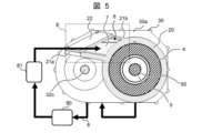
- 3 according to an embodiment of the present invention.
- 4 is a cross-sectional view of FIG. 3 along line D-D, according to an embodiment of the present invention; 5.
- the drive device 1 is used as a drive source for an electrically powered vehicle such as an electric car or a hybrid vehicle, and is mounted on the vehicle.
- the drive device 1 has a motor 2, a reduction gear 3 having a gear 31 for reducing the rotational speed of the motor 2, and a drive shaft (not shown) for driving tires.
- the motor 2 is housed in a motor housing 20, and has a stator 4 and a rotor 5.
- the reduction gear 3 is housed in a gear case 30.
- the motor housing 20 has a radially outer surface 20a.
- the gear case 30 has a motor side end surface 30a, which is the end surface on the motor housing 20 side in the axial direction.
- the gear case 30 also has a plurality of ribs 21 on the outside of the motor housing 20 that connect the motor side end surface 30a and the radially outer surface 20a of the motor housing 20.
- the ribs 21 include a first rib 21a and a second rib 21b.
- Space 6 is formed by the motor side end surface 30a of the gear case 30, the radial outer surface 20a of the motor housing 20, the first rib 21a, and the second rib 21b. Note that FIG. 1 shows the space 6 open, but a cover is provided to cover this opening.
- the reduction gear 3 has, in the gear case 30, an input shaft 32a which is a rotating shaft connected to the motor shaft 50, an output shaft 32c which is a rotating shaft connected to the drive shaft, and a counter shaft 32b which is a rotating shaft provided between the input shaft 32a and the output shaft 32c.
- the output shaft 32c has a differential gear 33 which generates a rotation difference between the left and right drive shafts (not shown).
- the differential gear 33 is housed in the gear case 30 and connected to the reduction gear 3.
- the multiple ribs 21a, 21b are positioned on the motor 2 side when the differential gear 33 is used as a reference in the axial direction.
- the input shaft 32a, counter shaft 32b, and output shaft 32c each have a gear 31.
- Each gear 31 is housed in a gear case 30.
- the inside of the gear case 30 is filled with oil to lubricate the gears 31. This oil also serves to cool the coil 40, which becomes hot when the motor is in operation, thereby realizing an oil-cooling system for the motor 2.
- the motor housing 20 and the gear case 30 have, externally, a pipe 8 through which the oil 7 that is supplied to the motor 2 and cools the motor 2 flows.
- a pump 80 for sending the oil 7 and an oil cooler 81 for cooling the oil 7 are provided midway along the path of the pipe 8.
- the space 6 (Fig. 1) functions as an oil tank for storing oil 7.
- the cover 22 seals the space 6 by covering the opening of the space 6 formed by the motor side end face 30a, the radially outer surface 20a, and the multiple ribs.
- the space 6 is filled with oil 7 that is supplied to the motor 2 and cools the motor 2.
- the motor housing 20 has an oil supply hole 23 that penetrates the wall of the motor housing 20 and supplies oil 7 to the coil 40.
- the oil supply hole 23 connects the interior of the motor housing 20 to the space 6 as a flow path for the oil 7.
- the oil supply hole 23 is also provided with a valve 24 that controls the conduction and interruption of the flow of the oil 7 between the interior of the motor housing 20 and the space 6.
- the pump 80 When cooling of the motor 2 is required, the pump 80 is started and the oil 7 stored in the lower part of the gear case 30 is circulated through the piping 8, heat exchanged in the oil cooler 81, and then sent to the space 6.
- the oil 7 sent to the space 6 controls the valve 24 to open the oil supply hole 23, and is supplied into the motor housing 20, thereby cooling the coil 40 of the stator 4. In this way, the oil 7 circulates through the piping 8 to cool the motor 2 and the reducer 3.
- the drive unit 1 When the vehicle is stopped, the drive unit 1 turns off the vehicle's power and then controls the valve 24 to close the oil supply hole 23. It then operates the pump 80 for a predetermined time to send a predetermined amount of oil 7 accumulated in the gear case 30 to the space 6 via the pipe 8. By stopping the pump 80 and ceasing the sending of the oil 7, the oil level of the oil 7 in the gear case 30 drops, while a predetermined amount of oil 7 is accumulated in the space 6. In this way, the vehicle starts from a state in which the oil level of the oil 7 in the gear case 30 is low, thereby reducing the agitation loss in the reducer 3.
- the drive unit 1 When the drive unit 1 is driven, it vibrates due to electromagnetic excitation forces generated in the gap between the rotor 5 and the stator 4, causing each part of the drive unit 1 to vibrate.
- the reducer 3 has three parallel shafts as shown in FIG. 2 and the output shaft 32c has a differential gear 33, the axial distance between the motor shaft 50 and the output shaft 32c becomes large, and the gear case 30 covering the differential gear 33 protrudes from the motor housing 20. Since the weight of the differential gear 33 is placed on the protruding gear case 30, the portion of the gear case 30 covering the differential gear 33 tends to vibrate more in the vertical and horizontal directions.
- the first rib 21a that defines the space 6, the second rib 21b that connects the motor side end face 30a of the gear case 30, and the cover 22 that covers the opening increase the vertical and horizontal rigidity of the gear case 30 that covers the differential device 33 ( Figure 2), and can reduce vibration. Also, even if the distance between the output shaft 32c and the motor shaft 50 increases, the motor side end face 30a of the gear case 30, the radial outer surface 20a of the motor housing 20, the first rib 21a, and the second rib 21b are adjusted accordingly to adjust the size of the space 6, thereby suppressing vibration of the drive unit 1.
- the first rib 21a is formed so as to be lower on the motor 2 side when viewed in radial cross section.
- the space 6 is provided so as to decrease in height from the output shaft 32c toward the motor shaft 50, with an extension line connecting the output shaft 32c and the motor shaft 50 being used as a plane reference. This makes it easier for the oil 7 stored in the space 6 to accumulate on the motor 2 side, increasing the amount of oil 7 that comes into contact with the radial outer surface 20a of the motor housing 20.
- the material from which the cover 22 is made is generally a metal material such as aluminum, but since there is a concern that the thin plate structure of the cover 22 will increase the amount of radiated sound caused by vibration, the cover 22 may be made of a resin material. This provides greater attenuation than a metal material such as aluminum, and can suppress radiated sound caused by vibration of the cover 22. Furthermore, since a resin material has better insulation properties than a metal material, it is easier to heat the oil 7 stored in the space 6. Therefore, even when the vehicle is parked for a short period of time in a low-temperature environment, the temperature of the oil 7 can be maintained at a low viscosity temperature, and an increase in the agitation loss of the oil 7 in the reduction gear 3 can be suppressed.
- the motor housing 20, the motor side end surface 30a of the gear case 30, the first rib 21a, and the second rib 21b may be formed integrally. This increases the rigidity of the gear case 30 that covers the differential device 33, and utilizes the weight of the oil 7 filled in the space 6 to suppress vertical and horizontal vibrations of the gear case 30 that covers the differential device 33.
- a drive unit 1 including a motor 2 housed in a motor housing 20, a reducer 3 connected to the motor 2 via a rotating shaft, and a gear case 30 housing the reducer 3, the gear case 30 having a motor side end face 30a which is the end face on the motor housing 20 side in the axial direction, and a plurality of ribs 21 outside the motor housing 20 connecting the motor side end face 30a to the radially outer surface 20a of the motor housing 20.
- a drive unit 1 can be provided which realizes reduced agitation loss of the oil 7 and reduced vibration.
- a cover 22 is provided to cover the opening of the space formed by the motor side end face 30a, the radially outer surface 20a, and the multiple ribs, sealing the space 6, and the space 6 is filled with oil 7 that is supplied to the motor 2 and cools the motor 2. This can reduce the agitation loss of the reducer 3.
- the differential gear 33 is housed in the gear case 30 and is connected to the reduction gear 3, and the multiple ribs 21 are arranged on the motor 2 side when the differential gear 33 is used as a reference in the axial direction. In this way, the refrigerant oil 7 that flows through both the motor 2 and the reduction gear 3 can be stored in a space separate from the motor 2 and the reduction gear 3.
- the multiple ribs 21 are formed so that the motor 2 side is lower when viewed in radial cross section. This lowers the viscosity of the oil 7, and reduces the churning loss of the oil 7 in the reduction gear 3 when the vehicle starts.
- the material of the cover 22 is resin. This makes it easier to transfer heat from the motor 2 to the oil 7 stored in the space 6.
- the motor housing 20 and the gear case 30 are formed as a single unit. This increases the rigidity of the gear case 30 that covers the differential device 33.
- the present invention is not limited to the above-described embodiment, and various modifications and other configurations can be combined without departing from the spirit of the invention. Furthermore, the present invention is not limited to those having all of the configurations described in the above-described embodiment, and also includes those in which some of the configurations have been omitted.
Landscapes
- Engineering & Computer Science (AREA)
- General Engineering & Computer Science (AREA)
- Mechanical Engineering (AREA)
- Power Engineering (AREA)
- General Details Of Gearings (AREA)
- Connection Of Motors, Electrical Generators, Mechanical Devices, And The Like (AREA)
- Motor Or Generator Cooling System (AREA)
Abstract
モータハウジングに収納されるモータと、回転軸を介して前記モータと接続される減速機と、前記減速機を収納するギアケースと、を備える駆動装置であって、前記ギアケースは、軸方向において前記モータハウジング側の端面であるモータ側端面を有し、かつ、前記モータハウジングの外部において、前記モータ側端面と前記モータハウジングの径方向外側面とを接続する複数のリブを有する。
Description
本発明は、駆動装置に関する。
電気自動車の駆動装置として、モータとインバータおよび減速機を一体化し、小型化・軽量化・高出力化を実現した駆動装置が知られている。このような駆動装置は、高速回転時に、モータを構成するステータのコイルや軸受等が高温となるため、冷却する必要がある。
冷却方法の一つとして、オイルをモータのコイルにかけてコイルを冷却する油冷モータ構造が知られている。例えば、特許文献1の駆動装置では、モータの油冷を効率的に行うことを目的とし、モータハウジング内部のリブによりロータの回転によって掻き上げられたオイルを溜めるキャッチタンクを設け、モータとキャッチタンクをオイルが循環し続ける構成が開示されている。
特許文献1に記載の技術では、例えば、冬の時期や寒冷地等の低温環境において、温度が下がってオイルの粘度が高い状態で車両を始動させると、ロータ下部に溜まった粘度の高いオイルによって攪拌抵抗の損失が大きくなるため、オイルを温める必要がある。また、減速機が平行三軸で出力軸に差動装置を持つ場合、モータ軸と出力軸との距離が大きくなることや、差動装置を覆うギアケースがモータハウジングから張り出す構造となることから、差動装置を覆うギアケースの振動が大きくなる傾向があるため、この振動を抑制する必要がある。
モータハウジングに収納されるモータと、回転軸を介して前記モータと接続される減速機と、前記減速機を収納するギアケースと、を備える駆動装置であって、前記ギアケースは、軸方向において前記モータハウジング側の端面であるモータ側端面を有し、かつ、前記モータハウジングの外部において、前記モータ側端面と前記モータハウジングの径方向外側面とを接続する複数のリブを有する。
本発明によれば、オイルの撹拌損失の低減および振動の低減を実現した駆動装置を提供できる。
以下、図面を参照して本発明の実施形態を説明する。以下の記載および図面は、本発明を説明するための例示であって、説明の明確化のため、適宜、省略および簡略化がなされている。本発明は、他の種々の形態でも実施する事が可能である。特に限定しない限り、各構成要素は単数でも複数でも構わない。
図面において示す各構成要素の位置、大きさ、形状、範囲などは、発明の理解を容易にするため、実際の位置、大きさ、形状、範囲などを表していない場合がある。このため、本発明は、必ずしも、図面に開示された位置、大きさ、形状、範囲などに限定されない。
(一実施形態と全体構成)
(図1、図2)
駆動装置1は、電気自動車やハイブリッド車両などの電動車両の駆動源として用いられるものであり、車両に搭載される。駆動装置1は、モータ2と、モータ2の回転速度を減速するためのギア31を有する減速機3と、タイヤを駆動するドライブシャフト(図示せず)と、を有している。モータ2は、モータハウジング20内に収納され、ステータ4とロータ5とを有している。減速機3はギアケース30に収納される。
(図1、図2)
駆動装置1は、電気自動車やハイブリッド車両などの電動車両の駆動源として用いられるものであり、車両に搭載される。駆動装置1は、モータ2と、モータ2の回転速度を減速するためのギア31を有する減速機3と、タイヤを駆動するドライブシャフト(図示せず)と、を有している。モータ2は、モータハウジング20内に収納され、ステータ4とロータ5とを有している。減速機3はギアケース30に収納される。
モータハウジング20は、径方向外側面20aを有する。ギアケース30は、軸方向においてモータハウジング20側の端面であるモータ側端面30aを有する。また、ギアケース30は、モータハウジング20の外部において、モータ側端面30aとモータハウジング20の径方向外側面20aとを接続する複数のリブ21を有する。リブ21は、第1リブ21aと、第2リブ21bとを含む。
ギアケース30のモータ側端面30aと、モータハウジング20の径方向外側面20aと、第1リブ21aと、第2リブ21bとによって、空間6が形成される。なお、図1は空間6が開口している状態であるが、この開口部には開口部を覆うカバーが設けられる。
減速機3は、ギアケース30内に、モータ軸50と接続される回転軸である入力軸32aと、ドライブシャフトと接続される回転軸である出力軸32cと、入力軸32aと出力軸32cとの間に設けられる回転軸であるカウンター軸32bと、を有する。出力軸32cは、図示しない左右のドライブシャフトに回転差を発生させる差動装置33を有する。差動装置33は、ギアケース30内に収納され、かつ減速機3と接続される。複数のリブ21a,21bは、軸方向において差動装置33を基準にした場合、モータ2側に配置される。
入力軸32aとカウンター軸32bと出力軸32cは、それぞれギア31を備えている。各ギア31は、ギアケース30内に収容される。また、ギアケース30の内部には、ギア31を潤滑するためのオイルが充填される。このオイルは、駆動時に高温となるコイル40の冷却を兼ねており、これによりモータ2の油冷方式が実現できる。
(図3、図4)
モータハウジング20とギアケース30とは、外部において、モータ2に供給されてモータ2を冷却するオイル7を流通させる配管8を有している。配管8の経路の途中には、オイル7を送るためのポンプ80と、オイル7を冷却するためのオイルクーラ81と、がそれぞれ設けられる。
モータハウジング20とギアケース30とは、外部において、モータ2に供給されてモータ2を冷却するオイル7を流通させる配管8を有している。配管8の経路の途中には、オイル7を送るためのポンプ80と、オイル7を冷却するためのオイルクーラ81と、がそれぞれ設けられる。
空間6(図1)は、オイル7を溜めるためのオイルタンクとして機能する。カバー22は、モータ側端面30a、径方向外側面20aおよび複数のリブによって形成される空間6の開口部を覆うことで、空間6を密閉している。空間6には、モータ2に供給されてモータ2を冷却するオイル7が充填される。
モータハウジング20は、モータハウジング20の壁面を貫通し、オイル7をコイル40に供給するための給油孔23を有する。給油孔23は、モータハウジング20の内部と空間6とを、オイル7の流路として接続している。また、給油孔23には、オイル7のモータハウジング20の内部と空間6とを導通および流通の遮断を制御するバルブ24が設けられている。
モータ2の冷却が必要な場合、ポンプ80を始動させ、ギアケース30の下部に溜められたオイル7を、配管8内を流通し、オイルクーラ81で熱交換した上で空間6に送る。空間6に送られたオイル7は、バルブ24を制御して給油孔23を導通させ、モータハウジング20内に供給されることで、ステータ4のコイル40を冷却する。このようにして、配管8を介してオイル7は循環して、モータ2および減速機3の冷却を行う。
駆動装置1は、車両停止時には、車両の電源を切った後、バルブ24を制御して給油孔23を遮断する。そして、所定の時間の間ポンプ80を作動させ、ギアケース30内に溜まった所定量のオイル7を、配管8を介して空間6に送る。そして、ポンプ80を停止させてオイル7の送液を停止することで、ギアケース30内のオイル7の油面が下がり、一方で空間6にオイル7が所定量溜められた状態になる。このようにすることで、車両始動時にギアケース30内のオイル7の油面が低下した状態から始動するため、減速機3の攪拌損失を低減することができる。
駆動装置1は、駆動時にロータ5とステータ4の間の隙間に発生する電磁加振力により振動することで、駆動装置1の各部が振動する。減速機3は、図2に示すように平行三軸となっており、かつ出力軸32cに差動装置33を有する場合、モータ軸50と出力軸32cとの軸間距離が大きくなり、差動装置33を覆うギアケース30が、モータハウジング20から張り出す構造となる。張り出したギアケース30には、差動装置33の重量がかかるため、差動装置33を覆うギアケース30部の上下、左右方向の振動が大きくなる傾向である。
このようにすることで、空間6を構成する第1リブ21aと、ギアケース30のモータ側端面30aを結ぶ第2リブ21bと、開口を覆うカバー22が、差動装置33(図2)を覆うギアケース30部の上下および左右方向の剛性を高め、振動を低減することができる。また、出力軸32cとモータ軸50との間の距離が大きくなっていっても、それに伴って、ギアケース30のモータ側端面30aと、モータハウジング20の径方向外側面20aと、第1リブ21aと、第2リブ21bと、を調整して、空間6のサイズを調整することで、駆動装置1の振動を抑制できる。
(図5、図6)
第1リブ21aは、径方向断面で見て、モータ2側が低くなるよう形成されている。具体的には、出力軸32cとモータ軸50とを結んだ延長線を平面の基準として、空間6は出力軸32cからモータ軸50に向かって高さが低くなるように設けられる。これにより、空間6に貯留されたオイル7がモータ2側に溜まりやすくなり、モータハウジング20の径方向外側面20aに接触するオイル7を増加させている。
第1リブ21aは、径方向断面で見て、モータ2側が低くなるよう形成されている。具体的には、出力軸32cとモータ軸50とを結んだ延長線を平面の基準として、空間6は出力軸32cからモータ軸50に向かって高さが低くなるように設けられる。これにより、空間6に貯留されたオイル7がモータ2側に溜まりやすくなり、モータハウジング20の径方向外側面20aに接触するオイル7を増加させている。
これにより、冬の時期や寒冷地等の低温環境下で、オイル7の温度が低下して粘度が高い状態になることで、オイル7を冷却が必要な箇所に十分に行き渡らせることが困難な場合であっても、空間6内のオイル7をモータ2側に溜めて、径方向外側面20aに接触する状態を増加させておくことで、オイル7をモータ2の熱で温め、粘度を低くできる。そのため、低温環境下における車両始動時でも、ステータ4のコイル40等の冷却が必要な箇所にオイル7を行き渡らせやすくすることができるため、減速機3における車両始動時のオイル7の攪拌損失を低減し、モータ2の信頼性を向上することができる。
なお、カバー22を形成する材料は、例えば、アルミニウム等の金属材料が一般的であるが、カバー22が薄板構造となって振動に起因した放射音が大きくなることが懸念されるため、樹脂材で形成されていてもよい。このようにすることで、アルミニウムのような金属材料よりも減衰が大きく、カバー22の振動に起因した放射音を抑制することができる。また、樹脂材は、金属材料よりも断熱性が高いため、空間6に溜められたオイル7を温めやすくなるため、低温環境下で車両を短時間駐停車する場合でも、オイル7の温度を粘性の低い状態の温度に保つことができ、減速機3におけるオイル7の攪拌損失の上昇を抑えることができる。
なお、モータハウジング20と、ギアケース30のモータ側端面30aと、第1リブ21aと、第2リブ21bとは一体で形成されてもよい。これにより、差動装置33を覆うギアケース30の剛性を高めることができ、空間6に充填されるオイル7の重量を利用して、差動装置33を覆うギアケース30の上下および左右方向の振動を抑制することができる。
以上説明した本発明の実施形態によれば、以下の作用効果を奏する。
(1)モータハウジング20に収納されるモータ2と、回転軸を介してモータ2と接続される減速機3と、減速機3を収納するギアケース30と、を備える駆動装置1であって、ギアケース30は、軸方向においてモータハウジング20側の端面であるモータ側端面30aを有し、かつ、モータハウジング20の外部において、モータ側端面30aとモータハウジング20の径方向外側面20aとを接続する複数のリブ21を有する。このようにしたことで、オイル7の撹拌損失の低減および振動の低減を実現した駆動装置1を提供できる。
(2)モータ側端面30a、径方向外側面20aおよび複数のリブによって形成される空間の開口部を覆って空間6を密閉するカバー22を備え、空間6には、モータ2に供給されてモータ2を冷却するオイル7が充填される。このようにしたことで、減速機3の攪拌損失を低減することができる。
(3)ギアケース30に収納され、かつ減速機3と接続される差動装置33を備え、複数のリブ21は、軸方向において差動装置33を基準にした場合、モータ2側に配置される。このようにしたことで、モータ2と減速機3を両方とも介して流通する冷媒オイル7を、モータ2および減速機3とは異なる空間に溜めることができる。
(4)複数のリブ21は、径方向断面で見て、モータ2側が低くなるよう形成される。このようにしたことで、オイル7の粘土を低くし、減速機3における車両始動時のオイル7の攪拌損失を低減できる。
(5)カバー22の材質は、樹脂である。このようにしたことで、空間6に溜めているオイル7に対して、モータ2からの熱を伝達させやすくできる。
(6)モータハウジング20とギアケース30とは、一体に形成される。このようにしたことで、差動装置33を覆うギアケース30の剛性を高めることができる。
なお、本発明は上記の実施形態に限定されるものではなく、その要旨を逸脱しない範囲内で様々な変形や他の構成を組み合わせることができる。また本発明は、上記の実施形態で説明した全ての構成を備えるものに限定されず、その構成の一部を削除したものも含まれる。
1 駆動装置
2 モータ
3 減速機
4 ステータ
5 ロータ
6 空間
7 オイル
8 配管
20 モータハウジング
20a 径方向外側面
21 リブ
21a 第1リブ
21b 第2リブ
22 カバー
23 給油孔
24 バルブ
30 ギアケース
30a モータ側端面
31 ギア
32a 入力軸
32b カウンター軸
32c 出力軸
33 差動装置
40 コイル
50 モータ軸
80 ポンプ
81 オイルクーラ
2 モータ
3 減速機
4 ステータ
5 ロータ
6 空間
7 オイル
8 配管
20 モータハウジング
20a 径方向外側面
21 リブ
21a 第1リブ
21b 第2リブ
22 カバー
23 給油孔
24 バルブ
30 ギアケース
30a モータ側端面
31 ギア
32a 入力軸
32b カウンター軸
32c 出力軸
33 差動装置
40 コイル
50 モータ軸
80 ポンプ
81 オイルクーラ
Claims (6)
- モータハウジングに収納されるモータと、
回転軸を介して前記モータと接続される減速機と、
前記減速機を収納するギアケースと、を備える駆動装置であって、
前記ギアケースは、軸方向において前記モータハウジング側の端面であるモータ側端面を有し、かつ、前記モータハウジングの外部において、前記モータ側端面と前記モータハウジングの径方向外側面とを接続する複数のリブを有する
駆動装置。 - 請求項1に記載の駆動装置であって、
前記モータ側端面、前記径方向外側面および前記複数のリブによって形成される空間の開口部を覆って前記空間を密閉するカバーを備え、
前記空間には、前記モータに供給されて前記モータを冷却するオイルが充填される
駆動装置。 - 請求項1に記載の駆動装置であって、
前記ギアケースに収納され、かつ前記減速機と接続される差動装置を備え、
前記複数のリブは、軸方向において前記差動装置を基準にした場合、前記モータ側に配置される
駆動装置。 - 請求項1に記載の駆動装置であって、
前記複数のリブは、径方向断面で見て、前記モータ側が低くなるよう形成される
駆動装置。 - 請求項2に記載の駆動装置であって、
前記カバーの材質は、樹脂である
駆動装置。 - 請求項1に記載の駆動装置であって、
前記モータハウジングと前記ギアケースとは、一体に形成される
駆動装置。
Applications Claiming Priority (2)
| Application Number | Priority Date | Filing Date | Title |
|---|---|---|---|
| JP2023-111732 | 2023-07-06 | ||
| JP2023111732A JP2025009025A (ja) | 2023-07-06 | 2023-07-06 | 駆動装置 |
Publications (1)
| Publication Number | Publication Date |
|---|---|
| WO2025009533A1 true WO2025009533A1 (ja) | 2025-01-09 |
Family
ID=94171584
Family Applications (1)
| Application Number | Title | Priority Date | Filing Date |
|---|---|---|---|
| PCT/JP2024/023958 Ceased WO2025009533A1 (ja) | 2023-07-06 | 2024-07-02 | 駆動装置 |
Country Status (2)
| Country | Link |
|---|---|
| JP (1) | JP2025009025A (ja) |
| WO (1) | WO2025009533A1 (ja) |
Citations (5)
| Publication number | Priority date | Publication date | Assignee | Title |
|---|---|---|---|---|
| JP2016149877A (ja) * | 2015-02-12 | 2016-08-18 | 株式会社ミツバ | アクチュエータ |
| JP2020198675A (ja) * | 2019-05-31 | 2020-12-10 | 日産自動車株式会社 | 駆動システム |
| JP2022102766A (ja) * | 2020-12-25 | 2022-07-07 | 株式会社アイシン | 車両用駆動装置 |
| JP2022154481A (ja) * | 2021-03-30 | 2022-10-13 | 日本電産株式会社 | モータユニット |
| JP2023086034A (ja) * | 2021-12-09 | 2023-06-21 | 株式会社アイシン | 駆動装置 |
-
2023
- 2023-07-06 JP JP2023111732A patent/JP2025009025A/ja active Pending
-
2024
- 2024-07-02 WO PCT/JP2024/023958 patent/WO2025009533A1/ja not_active Ceased
Patent Citations (5)
| Publication number | Priority date | Publication date | Assignee | Title |
|---|---|---|---|---|
| JP2016149877A (ja) * | 2015-02-12 | 2016-08-18 | 株式会社ミツバ | アクチュエータ |
| JP2020198675A (ja) * | 2019-05-31 | 2020-12-10 | 日産自動車株式会社 | 駆動システム |
| JP2022102766A (ja) * | 2020-12-25 | 2022-07-07 | 株式会社アイシン | 車両用駆動装置 |
| JP2022154481A (ja) * | 2021-03-30 | 2022-10-13 | 日本電産株式会社 | モータユニット |
| JP2023086034A (ja) * | 2021-12-09 | 2023-06-21 | 株式会社アイシン | 駆動装置 |
Also Published As
| Publication number | Publication date |
|---|---|
| JP2025009025A (ja) | 2025-01-20 |
Similar Documents
| Publication | Publication Date | Title |
|---|---|---|
| JP7517044B2 (ja) | 動力伝達装置およびモータユニット | |
| JP7639709B2 (ja) | モータユニット | |
| CN112449739B (zh) | 具有冷却功能的电动驱动器 | |
| CN114901499B (zh) | 驱动装置 | |
| JP7537267B2 (ja) | 動力伝達装置、モータユニット、及び車両 | |
| CN113193679B (zh) | 马达单元 | |
| JP7639482B2 (ja) | モータユニット | |
| CN109790914A (zh) | 车辆用驱动装置 | |
| JP2022018909A (ja) | 駆動装置のシール構造 | |
| WO2010116689A1 (ja) | 車両駆動装置の発熱部冷却構造 | |
| US12184154B2 (en) | Drive device and vehicle | |
| WO2019208081A1 (ja) | モータユニットおよび車両駆動装置 | |
| WO2014045707A1 (ja) | 車両用駆動装置 | |
| JP3508202B2 (ja) | 車両駆動用電動機 | |
| US10958136B2 (en) | Drive apparatus | |
| WO2019208083A1 (ja) | モータユニット | |
| US11139720B2 (en) | Drive apparatus | |
| WO2019208084A1 (ja) | モータユニットおよびモータユニットの制御方法 | |
| WO2023006217A1 (en) | Electric drive for a motor vehicle | |
| JP2025009025A (ja) | 駆動装置 | |
| JP7468313B2 (ja) | 駆動装置 | |
| KR101781747B1 (ko) | 전동식 듀얼 펌프 | |
| JP2013176247A (ja) | 回転電機の潤滑装置 | |
| US12359717B2 (en) | Vehicle drive device | |
| CN117999729A (zh) | 旋转电机 |
Legal Events
| Date | Code | Title | Description |
|---|---|---|---|
| 121 | Ep: the epo has been informed by wipo that ep was designated in this application |
Ref document number: 24836046 Country of ref document: EP Kind code of ref document: A1 |
|
| NENP | Non-entry into the national phase |
Ref country code: DE |
|
| 122 | Ep: pct application non-entry in european phase |
Ref document number: 24836046 Country of ref document: EP Kind code of ref document: A1 |