WO2025009282A1 - アキシャルギャップ型モータ、送風装置、及び空気調和機 - Google Patents
アキシャルギャップ型モータ、送風装置、及び空気調和機 Download PDFInfo
- Publication number
- WO2025009282A1 WO2025009282A1 PCT/JP2024/018933 JP2024018933W WO2025009282A1 WO 2025009282 A1 WO2025009282 A1 WO 2025009282A1 JP 2024018933 W JP2024018933 W JP 2024018933W WO 2025009282 A1 WO2025009282 A1 WO 2025009282A1
- Authority
- WO
- WIPO (PCT)
- Prior art keywords
- rotor
- holes
- axial direction
- viewed
- stator
- Prior art date
- Legal status (The legal status is an assumption and is not a legal conclusion. Google has not performed a legal analysis and makes no representation as to the accuracy of the status listed.)
- Ceased
Links
Images








Classifications
-
- H—ELECTRICITY
- H02—GENERATION; CONVERSION OR DISTRIBUTION OF ELECTRIC POWER
- H02K—DYNAMO-ELECTRIC MACHINES
- H02K5/00—Casings; Enclosures; Supports
- H02K5/24—Casings; Enclosures; Supports specially adapted for suppression or reduction of noise or vibrations
-
- F—MECHANICAL ENGINEERING; LIGHTING; HEATING; WEAPONS; BLASTING
- F24—HEATING; RANGES; VENTILATING
- F24F—AIR-CONDITIONING; AIR-HUMIDIFICATION; VENTILATION; USE OF AIR CURRENTS FOR SCREENING
- F24F1/00—Room units for air-conditioning, e.g. separate or self-contained units or units receiving primary air from a central station
- F24F1/06—Separate outdoor units, e.g. outdoor unit to be linked to a separate room comprising a compressor and a heat exchanger
- F24F1/38—Fan details of outdoor units, e.g. bell-mouth shaped inlets or fan mountings
-
- H—ELECTRICITY
- H02—GENERATION; CONVERSION OR DISTRIBUTION OF ELECTRIC POWER
- H02K—DYNAMO-ELECTRIC MACHINES
- H02K1/00—Details of the magnetic circuit
- H02K1/06—Details of the magnetic circuit characterised by the shape, form or construction
- H02K1/12—Stationary parts of the magnetic circuit
- H02K1/14—Stator cores with salient poles
- H02K1/146—Stator cores with salient poles consisting of a generally annular yoke with salient poles
-
- H—ELECTRICITY
- H02—GENERATION; CONVERSION OR DISTRIBUTION OF ELECTRIC POWER
- H02K—DYNAMO-ELECTRIC MACHINES
- H02K1/00—Details of the magnetic circuit
- H02K1/06—Details of the magnetic circuit characterised by the shape, form or construction
- H02K1/22—Rotating parts of the magnetic circuit
- H02K1/27—Rotor cores with permanent magnets
- H02K1/2793—Rotors axially facing stators
- H02K1/2795—Rotors axially facing stators the rotor consisting of two or more circumferentially positioned magnets
- H02K1/2798—Rotors axially facing stators the rotor consisting of two or more circumferentially positioned magnets where both axial sides of the stator face a rotor
-
- H—ELECTRICITY
- H02—GENERATION; CONVERSION OR DISTRIBUTION OF ELECTRIC POWER
- H02K—DYNAMO-ELECTRIC MACHINES
- H02K21/00—Synchronous motors having permanent magnets; Synchronous generators having permanent magnets
- H02K21/12—Synchronous motors having permanent magnets; Synchronous generators having permanent magnets with stationary armatures and rotating magnets
- H02K21/24—Synchronous motors having permanent magnets; Synchronous generators having permanent magnets with stationary armatures and rotating magnets with magnets axially facing the armatures, e.g. hub-type cycle dynamos
-
- H—ELECTRICITY
- H02—GENERATION; CONVERSION OR DISTRIBUTION OF ELECTRIC POWER
- H02K—DYNAMO-ELECTRIC MACHINES
- H02K29/00—Motors or generators having non-mechanical commutating devices, e.g. discharge tubes or semiconductor devices
- H02K29/03—Motors or generators having non-mechanical commutating devices, e.g. discharge tubes or semiconductor devices with a magnetic circuit specially adapted for avoiding torque ripples or self-starting problems
-
- H—ELECTRICITY
- H02—GENERATION; CONVERSION OR DISTRIBUTION OF ELECTRIC POWER
- H02K—DYNAMO-ELECTRIC MACHINES
- H02K7/00—Arrangements for handling mechanical energy structurally associated with dynamo-electric machines, e.g. structural association with mechanical driving motors or auxiliary dynamo-electric machines
- H02K7/14—Structural association with mechanical loads, e.g. with hand-held machine tools or fans
-
- F—MECHANICAL ENGINEERING; LIGHTING; HEATING; WEAPONS; BLASTING
- F24—HEATING; RANGES; VENTILATING
- F24F—AIR-CONDITIONING; AIR-HUMIDIFICATION; VENTILATION; USE OF AIR CURRENTS FOR SCREENING
- F24F1/00—Room units for air-conditioning, e.g. separate or self-contained units or units receiving primary air from a central station
- F24F1/0007—Indoor units, e.g. fan coil units
- F24F1/0018—Indoor units, e.g. fan coil units characterised by fans
- F24F1/0022—Centrifugal or radial fans
-
- H—ELECTRICITY
- H02—GENERATION; CONVERSION OR DISTRIBUTION OF ELECTRIC POWER
- H02K—DYNAMO-ELECTRIC MACHINES
- H02K2213/00—Specific aspects, not otherwise provided for and not covered by codes H02K2201/00 - H02K2211/00
- H02K2213/03—Machines characterised by numerical values, ranges, mathematical expressions or similar information
Definitions
- This disclosure relates to an axial gap type motor, a blower, and an air conditioner.
- an axial gap type motor that includes a rotor and a stator that faces the rotor in the axial direction of the rotor via an air gap.
- the space between the rotor and stator (air gap) has a natural frequency. Therefore, when the motor is running, minute axial vibrations of the rotor can cause abnormal noise with a peak sound pressure level at a frequency near the natural frequency of the air gap.
- the axial gap motor of the first aspect includes a rotor and a stator.
- the rotor is disk-shaped.
- the stator faces the rotor in the axial direction of the rotor via an air gap.
- the stator has multiple stator cores and coils wound around each stator core.
- the multiple stator cores are arranged in an annular shape when viewed from the axial direction of the rotor.
- the rotor has multiple through holes that penetrate the rotor in the axial direction. The multiple through holes are provided radially inward of the rotor than the coils when viewed from the axial direction of the rotor.
- the axial gap motor of the first aspect provides a through hole in the center of the rotor to make the natural frequency of the air gap higher than a predetermined frequency, thereby reducing the sound pressure level at frequencies near the natural frequency when no through hole is provided. This reduces abnormal noise generated by the motor.
- the axial gap motor of the second aspect is the axial gap motor of the first aspect, in which the multiple through holes are provided in a circular first region centered on the rotation axis of the rotor when viewed from the axial direction of the rotor.
- the radius of the first region is 40% or less of the radius of the rotor.
- the axial gap motor of the third aspect is an axial gap motor of the first or second aspect, in which the first ratio, which is the ratio between the total area of the multiple through holes and the opening area of the outer edge portion of the air gap, is 3% or more.
- the axial gap motor of the fourth aspect is the axial gap motor of the third aspect, in which the first ratio is 10% or more.
- the fifth aspect of the axial gap motor is the third aspect of the axial gap motor, in which the first ratio is 20% or more.
- the axial gap motor of the sixth aspect is an axial gap motor of any one of the third to fifth aspects, in which the first ratio is 40% or less.
- the seventh aspect of the axial gap motor is an axial gap motor according to any one of the first to sixth aspects, in which the multiple through holes are arranged along the circumference of a first circle centered on the rotation axis of the rotor, so that the centers of the through holes are located on the circumference of the first circle when viewed from the axial direction of the rotor.
- the axial gap motor of the eighth aspect is an axial gap motor of any one of the first to seventh aspects, and includes a pair of rotors and a stator sandwiched between the pair of rotors.
- the blower device of the ninth aspect includes an axial gap motor of any one of the first to eighth aspects and a fan driven by the axial gap motor.
- An air conditioner according to a tenth aspect is provided with a blower according to a ninth aspect.
- FIG. 1 is an external perspective view of a blower device 100 according to a first embodiment.
- FIG. 2 is an external perspective view of a first fan 20, a second fan 30, and a motor 40 according to the first embodiment.
- FIG. 2 is a side view of the first fan 20, the second fan 30, and the motor 40 of the first embodiment.
- FIG. 2 is an exploded perspective view of a first fan 20, a second fan 30, and a motor 40 according to the first embodiment.
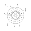
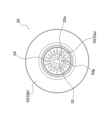
- FIG. 2 is a plan view of a first rotor 50 according to the first embodiment.
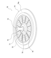
- FIG. 2 is an external perspective view of a first rotor 50 according to the first embodiment.
- FIG. 2 is a plan view of a second rotor 60 according to the first embodiment.
- FIG. 2 is an external perspective view of a second rotor 60 according to the first embodiment.
- FIG. 2 is a plan view of a stator 70 according to the first embodiment.
- FIG. 2 is an external perspective view of a stator 70 according to the first embodiment.
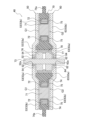
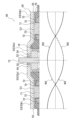
- FIG. 2 is a cross-sectional view of the motor 40 of the first embodiment.
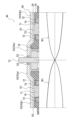
- 1 is a diagram for explaining a standing wave having a natural frequency of the first air gap G1;
- FIG. 2 is a diagram showing a standing wave in a case where the first rotor 50 does not have a through hole 54;
- 1 is a diagram for explaining a standing wave having a natural frequency of the first air gap G1;
- FIG. 1 is a diagram for explaining a standing wave having a natural frequency of the first air gap G1;
- FIG. 2 is a diagram showing a standing wave when the first rotor 50 has a through hole 54; 11 is an example of measurement data showing the relationship between the frequency of the micro-vibration applied to the first rotor 50 and the sound pressure level. 13 is an example of measurement data of noise generated when the motor 40 is driven. 13 is an example of measurement data showing the relationship between the number of through holes 54, 64 and the sound pressure level.
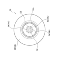
- FIG. 11 is a plan view of a first rotor 50 according to a second embodiment.
- FIG. 11 is a plan view of a first rotor 50 according to a third embodiment.
- FIG. 11 is a plan view of a first rotor 50 according to a fourth embodiment.
- FIG. 11 is a plan view of the first rotor 50 of the modified example D-1.
- FIG. 11 is a plan view of the first rotor 50 of the modified example D-2.
- FIG. 11 is a plan view of the first rotor 50 of the modified example D-3.
- the blower 100 of the first embodiment of the present disclosure is used in, for example, an air conditioner.
- the air conditioner includes an indoor unit equipped with the blower 100, and an outdoor unit connected to the indoor unit via a refrigerant circuit.
- the refrigerant circuit includes, for example, a compressor, a four-way switching valve, an outdoor heat exchanger, an electric expansion valve, an indoor heat exchanger, and an accumulator.
- the blower device 100 includes a housing 10, a first fan 20, a second fan 30, and a motor 40.
- the first fan 20 and the second fan 30 are centrifugal fans such as sirocco fans.
- the housing 10 has a cylindrical portion 10a that houses the first fan 20 and the second fan 30, and a blowing portion 10b that protrudes from the cylindrical portion 10a.
- a flange 13 having a first suction port 11 is provided at one end of the cylindrical portion 10a
- a flange (not shown) having a second suction port 12 is provided at the other end of the cylindrical portion 10a.
- Bell mouths 14 are provided at the first suction port 11 and the second suction port 12. In FIG. 1, only the bell mouth 14 on the first suction port 11 side is shown.
- a ring-shaped motor fixing portion 10c is provided along the circumferential direction on the outer periphery of the central portion in the longitudinal direction of the cylindrical portion 10a.
- the blowing portion 10b has a quadrangular pyramid shape that gradually widens toward the outside along the circumferential direction of the cylindrical portion 10a.
- An air outlet 15 is provided at the outer end of the blowing portion 10b.
- the first fan 20 has a disk-shaped end plate 21, a number of blades 22, and an annular member 23.
- the blades 22 are connected to one side of the end plate 21 and are arranged at intervals along the circumferential direction of the end plate 21.
- the annular member 23 is connected to the end of the blades 22 on the side opposite to the side to which the end plate 21 is connected.
- the second fan 30 has a disk-shaped end plate 31, a number of blades 32, and an annular member 33.
- the blades 32 are connected to one side of the end plate 31 and are arranged at intervals along the circumferential direction of the end plate 31.
- the annular member 33 is connected to the ends of the blades 32 on the side opposite to the side to which the end plate 31 is connected.
- the motor 40 is an axial gap type motor. As shown in FIG. 4, the motor 40 has a disk-shaped first rotor 50, a disk-shaped second rotor 60, and a disk-shaped stator 70.
- the direction along the rotation axis of the first rotor 50 and the second rotor 60 will be referred to as the "axial direction.”
- the stator 70 is disposed between the first rotor 50 and the second rotor 60 in the axial direction.
- the first rotor 50 is disposed opposite the end plate 21 of the first fan 20. As shown in FIG. 3 , the end plate 21 of the first fan 20 is disposed in a non-contact state with the first rotor 50 of the motor 40.
- the first rotor 50 has a boss portion 52 and a magnet member 53 provided on the outer periphery of the boss portion 52.
- the boss portion 52 is molded from metal.
- the boss portion 52 has a cylindrical shape.
- the boss portion 52 has a circular hole 52a in the center.
- the magnet member 53 is molded from a plastic magnet.
- the magnet member 53 has a disk shape. When molding the magnet member 53, the boss portion 52 is attached to a mold as an insert part, so that the boss portion 52 and the magnet member 53 are molded as a single unit.
- the magnet member 53 has a protruding portion 53a that does not act as a magnet, and a magnet portion 53b that acts as a magnet.
- the protruding portion 53a is a portion of the magnet member 53 that protrudes in the axial direction on the side of the first fan 20 and is recessed on the side of the stator 70.
- the protruding portion 53a has a circular shape when viewed from the axial direction.
- the boss portion 52 is located at the center of the protruding portion 53a.
- the magnet portion 53b is located around the protruding portion 53a. As shown in FIG. 5, in the magnet portion 53b, the south poles and north poles are arranged alternately in the circumferential direction of the magnet member 53.
- the second rotor 60 is disposed opposite the end plate 31 of the second fan 30. As shown in FIG. 3, the end plate 31 of the second fan 30 is disposed in a non-contact state with the second rotor 60 of the motor 40.
- the second rotor 60 has a boss portion 62 and a magnet member 63 provided on the outer periphery of the boss portion 62.
- the boss portion 62 is molded from metal.
- the boss portion 62 has a cylindrical shape.
- the boss portion 62 has a circular hole 62a in the center.
- the magnet member 63 is molded from a plastic magnet.
- the magnet member 63 has a disk shape.
- the magnet member 63 has a protruding portion 63a that does not act as a magnet, and a magnet portion 63b that acts as a magnet.
- the protruding portion 63a is a portion of the magnet member 63 that protrudes in the axial direction on the side of the second fan 30 and is recessed on the side of the stator 70.
- the protruding portion 63a has a circular shape when viewed from the axial direction.
- the boss portion 62 is located at the center of the protruding portion 63a.
- the magnet portion 63b is located around the protruding portion 63a. As shown in FIG. 7, in the magnet portion 63b, the south poles and north poles are arranged alternately in the circumferential direction of the magnet member 63.
- the stator 70 has a plurality of stator cores 71, a plurality of coils 72, a shaft 73, a molded portion 74, an insulator 75, a first bearing 76, a second bearing 77, and a bearing housing 78.
- the multiple stator cores 71 are arranged in an annular shape at intervals along the circumferential direction of the stator 70.
- Each coil 72 is formed by winding a wire around each stator core 71.
- the insulator 75 insulates the stator core 71 from the coils 72.
- the shaft 73 extends axially through the circular hole 52a of the first rotor 50 toward the first fan 20.
- the shaft 73 extends axially through the circular hole 62a of the second rotor 60 toward the second fan 30.
- the shaft 73 is fixed to the inner circumferential surface of the boss portion 52 of the first rotor 50 and the end plate 21 of the first fan 20.
- the shaft 73 is fixed to the inner circumferential surface of the boss portion 62 of the second rotor 60 and the end plate 31 of the second fan 30.
- the molded portion 74 is a disk-shaped member formed by resin molding so as to surround the stator core 71 and the coil 72.
- the molded portion 74 has an outer edge portion 74a that protrudes from the side of the molded portion 74.
- the outer edge portion 74a of the molded portion 74 is fixed by the motor fixing portion 10c of the housing 10.
- the first bearing 76 is provided on the first rotor 50 side in the axial direction.
- the second bearing 77 is provided on the second rotor 60 side in the axial direction.
- the first bearing 76 and the second bearing 77 rotatably support the shaft 73.
- the bearing housing 78 accommodates the first bearing 76 and the second bearing 77.
- the stator 70 faces the first rotor 50 in the axial direction via a first air gap G1.
- the stator 70 faces the second rotor 60 in the axial direction via a second air gap G2.
- the axial dimensions of the first air gap G1 and the second air gap G2 are, for example, 0.5 mm to 2 mm.
- the outer diameter of the stator 70 is larger than the outer diameter of the first rotor 50 and the outer diameter of the second rotor 60.
- the outer diameter of the molded portion 74 excluding the outer edge portion 74a is approximately the same as the outer diameter of the first rotor 50 and the outer diameter of the second rotor 60.
- the center of the molded portion 74 of the stator 70 protrudes in the axial direction on the side of the first fan 20 to match the shape of the magnet member 53 of the first rotor 50.
- the center of the molded portion 74 of the stator 70 protrudes in the axial direction on the side of the second fan 30 to match the shape of the magnet member 63 of the second rotor 60.
- the first rotor 50 has a plurality of through holes 54 penetrating in the axial direction.
- the plurality of through holes 54 are provided in the protruding portion 53a of the magnet member 53.
- the plurality of through holes 54 are provided radially inward of the first rotor 50 relative to the coils 72 when viewed from the axial direction.
- the through holes 54 communicate the space between the first rotor 50 and the end plate 21 with the first air gap G1.
- the first rotor 50 has ten through holes 54 arranged along the circumference of a first circle C1 centered on the rotation axis of the first rotor 50 when viewed from the axial direction.
- These through holes 54 have a circular shape when viewed from the axial direction and have the same dimensions (diameter).
- the ten through holes 54 are arranged at equal intervals along the circumference of the first circle C1.
- the diameter of the through holes 54 is, for example, 2.5 mm.
- the multiple through holes 54 are provided in a circular first region R1 centered on the rotation axis of the first rotor 50 when viewed from the axial direction.
- the first region R1 is substantially the same as the region occupied by the boss portion 52 and the protrusion portion 53a of the first rotor 50.
- the boss portion 52 and the protrusion portion 53a are located radially inward of the first rotor 50 relative to the coil 72.
- the radius of the first region R1 is 40% or less of the radius of the first rotor 50.
- the radius of the first rotor 50 is the dimension from the rotation axis of the first rotor 50 to the outer edge of the first rotor 50 when the first rotor 50 is viewed in the axial direction.
- the radius of the first region R1 is substantially less than the dimension from the rotation axis of the first rotor 50 to the outer edge of the protruding portion 53a when the first rotor 50 is viewed in the axial direction.
- the radius of the first region R1 may be 25% or less of the radius of the first rotor 50.
- the radius of the first region R1 may be 20% or less of the radius of the first rotor 50.
- the radius of the first region R1 may be 15% or less of the radius of the first rotor 50.
- the multiple through holes 54 are provided outside the boss portion 52 when viewed from the axial direction. Therefore, for example, it is preferable that the radius of the first region R1 is 5% or more of the radius of the first rotor 50.
- the second rotor 60 has a plurality of through holes 64 that penetrate in the axial direction.
- the plurality of through holes 64 are provided in the protruding portion 63a of the magnet member 63. As shown in FIG. 11, the plurality of through holes 64 are provided radially inward of the second rotor 60 from the coil 72 when viewed from the axial direction.
- the through holes 64 communicate the space between the second rotor 60 and the end plate 31 with the second air gap G2.
- the second rotor 60 has ten through holes 64 arranged along the circumference of a second circle C2 centered on the rotation axis of the second rotor 60 when viewed from the axial direction.
- These through holes 64 have a circular shape when viewed from the axial direction and have the same dimensions (diameter).
- the ten through holes 64 are arranged at equal intervals along the circumference of the second circle C2.
- the diameter of the through holes 64 is, for example, 2.5 mm.
- the multiple through holes 64 are provided in a circular second region R2 centered on the rotation axis of the second rotor 60 when viewed from the axial direction.
- the second region R2 is substantially the same as the region occupied by the boss portion 62 and the protrusion portion 63a of the second rotor 60.
- the boss portion 62 and the protrusion portion 63a are located radially inward of the second rotor 60 relative to the coil 72.
- the radius of the second region R2 is 40% or less of the radius of the second rotor 60.
- the radius of the second rotor 60 is the dimension from the rotation axis of the second rotor 60 to the outer edge of the second rotor 60 when the second rotor 60 is viewed in the axial direction.
- the radius of the second region R2 is substantially less than the dimension from the rotation axis of the second rotor 60 to the outer edge of the protruding portion 63a when the second rotor 60 is viewed in the axial direction.
- the radius of the second region R2 may be 25% or less of the radius of the second rotor 60.
- the radius of the second region R2 may be 20% or less of the radius of the second rotor 60.
- the radius of the second region R2 may be 15% or less of the radius of the second rotor 60.
- the multiple through holes 64 are provided outside the boss portion 62 when viewed from the axial direction. Therefore, for example, it is preferable that the radius of the second region R2 is 5% or more of the radius of the second rotor 60.
- the first ratio which is the ratio between the total area of the multiple through holes 54 of the first rotor 50 and the opening area of the outer edge portion of the first air gap G1, is 3% or more.
- the first ratio means the ratio of the total area of the multiple through holes 54 to the opening area of the outer edge portion of the first air gap G1.
- the total area of the multiple through holes 54 is the sum of the areas occupied by the through holes 54 when the first rotor 50 is viewed from the axial direction.
- the opening area is the area occupied by the first air gap G1 when the first air gap G1 is viewed from the horizontal direction.
- the opening area is calculated by multiplying the axial dimension of the first air gap G1 at the outer edge of the first rotor 50 by the length of the outer edge of the first rotor 50.
- the length of the outer edge of the first rotor 50 is calculated by multiplying the diameter of the first rotor 50 when viewed from the axial direction by pi.
- the first ratio may be 10% or more.
- the first ratio may be 20% or more. It is preferable that the first ratio is 40% or less.
- the second ratio which is the ratio between the total area of the multiple through holes 64 of the second rotor 60 and the opening area of the outer edge portion of the second air gap G2, is 3% or more.
- the total area of the multiple through holes 64 is the sum of the areas occupied by the through holes 64 when the second rotor 60 is viewed from the axial direction.
- the opening area is the area occupied by the second air gap G2 when the second air gap G2 is viewed from the horizontal direction.
- the opening area is calculated by multiplying the axial dimension of the second air gap G2 at the outer edge of the second rotor 60 by the length of the outer edge of the second rotor 60.
- the length of the outer edge of the second rotor 60 is calculated by multiplying the diameter of the second rotor 60 when viewed from the axial direction by pi.
- the second ratio may be 10% or more.
- the second ratio may be 20% or more. It is preferable that the second ratio is 40% or less.
- the axial gap motor 40 has a first air gap G1 between the first rotor 50 and the stator 70, and a second air gap G2 between the second rotor 60 and the stator 70.
- the air gaps G1 and G2 have natural frequencies. Therefore, while the motor 40 is running, minute axial vibrations of the rotors 50 and 60 may cause abnormal noise having a peak in sound pressure level at a frequency near the natural frequency of the air gaps G1 and G2.
- a standing wave having a natural frequency of the first air gap G1.
- the standing wave represents a radial vibration of the air in the first air gap G1.
- the amplitude of the standing wave is positive.
- the amplitude of the standing wave is negative.
- the first wave W1 shown in FIG. 12 represents a standing wave when the first rotor 50 does not have a through hole 54.
- the second wave W2 shown in FIG. 13 represents a standing wave when the first rotor 50 has a through hole 54.
- the standing wave shown by the dotted line is 180° out of phase with the standing wave shown by the solid line.
- the opening ends of the first air gap G1 are only at both ends 55 of the first air gap G1. Therefore, as shown in FIG. 12, the antinodes (positions where the amplitude is maximum) of the first wave W1 are located only at both ends 55 of the first air gap G1 in the radial direction of the first rotor 50.
- the opening ends of the first air gap G1 are both ends 55 of the first air gap G1 and the through hole 54. Therefore, as shown in FIG.
- the antinodes of the second wave W2 are located at both ends 55 of the first air gap G1 and in the center where the through hole 54 is located. Therefore, the natural frequency of the second wave W2 is approximately twice the natural frequency of the first wave W1. In this way, the natural frequency of the first air gap G1 can be changed by providing the through hole 54 near the node (the position where the amplitude is zero) of the first wave W1 in the radial direction of the first rotor 50.
- the node of the first wave W1 is located in the center of the first air gap G1 in the radial direction of the first rotor 50.
- the horizontal axis of FIG. 14 represents the frequency of the micro-vibration of the first rotor 50.
- the vertical axis of FIG. 14 represents the sound pressure level of abnormal noise.
- the first measurement data represents the measurement data when the first rotor 50 does not have a through hole 54.
- the second measurement data represents the measurement data when the first rotor 50 has a through hole 54. From the first measurement data, the natural frequency of the first wave W1 shown in FIG. 12 is about 1150 Hz. From the second measurement data, the natural frequency of the second wave W2 shown in FIG.
- the natural frequency of the first air gap G1 is about doubled by providing the through hole 54 in the first rotor 50. It was also observed that the sound pressure level at the natural frequency of 1150 Hz when the first rotor 50 has a through hole 54 is lower than the sound pressure level at the natural frequency of 2050 Hz when the first rotor 50 does not have a through hole 54.
- abnormal noise having a peak sound pressure level at a frequency near the natural frequency of the first air gap G1 is reduced.
- multiple through holes 64 in the center of the second rotor 60 and making the natural frequency of the second air gap G2 higher than a predetermined frequency abnormal noise having a peak sound pressure level at a frequency near the natural frequency of the second air gap G2 is reduced.
- FIG. 15 shows an example of measurement data of noise generated when the motor 40 is driven.
- the third measurement data represents measurement data when the rotors 50, 60 do not have through holes 54, 64.
- the fourth measurement data represents measurement data when the rotors 50, 60 have through holes 54, 64.
- FIG. 15 it was observed that by providing the rotors 50, 60 with through holes 54, 64, the values of multiple peaks of the sound pressure level at frequencies around 1150 Hz were reduced.
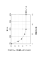
- FIG. 16 shows measurement data indicating the relationship between the number of through holes 54 of the first rotor 50 and the sound pressure level of the generated abnormal noise.
- the horizontal axis of FIG. 16 indicates the number of through holes 54.
- the vertical axis of FIG. 16 indicates the sound pressure level at 1100 Hz. 1100 Hz is the frequency at which the sound pressure level of the abnormal noise generated when the first rotor 50 does not have a through hole 54 is maximum.
- the horizontal axis of the graph in FIG. 16 indicates the correspondence between the number of through holes 54 and the first ratio. Since all the through holes 54 have the same dimensions, the first ratio is proportional to the number of through holes 54.
- the first ratio is 40%
- the first ratio is 20%
- the range of the first ratio of the measurement data is 0% to 40%.
- FIG. 16 shows measurement data when the number of through holes 54 in the first rotor 50 is 0, 5, 10, 20, 30, and 60.
- the first ratio is 0%, 3.3%, 6.7%, 13%, 20%, and 40%, respectively.
- the number, shape, and position of the through holes 64 in the second rotor 60 are the same as the number, shape, and position of the through holes 54 in the first rotor 50. Therefore, the second ratio is the same as the first ratio.
- the sound pressure level decreased as the first ratio, which is the ratio of the total area of the through holes 54 to the opening area of the outer edge of the first air gap G1, increased.
- the first ratio increases from 0% to 20%, a significant decrease in the sound pressure level was observed. Specifically, it was confirmed that when the first ratio was 3.3%, the sound pressure level was reduced by approximately 10 dB compared to when the first ratio was 0%. It was confirmed that when the first ratio was 20%, the sound pressure level was reduced by approximately 20 dB compared to when the first ratio was 0%. It was also observed that there was almost no decrease in the sound pressure level as the first ratio increased from 20% to 40%.
- the first ratio is preferably 3.3% to 20%, more preferably 6.7% to 20%, and even more preferably 13% to 20%.
- the second ratio is as small as possible.
- the second ratio is as large as possible. Therefore, like the first ratio, the second ratio is preferably 3.3% to 20%, more preferably 6.7% to 20%, and even more preferably 13% to 20%.
- the blower device 100 of the second embodiment has a basic configuration and operation in common with the blower device 100 of the first embodiment.
- the difference between the second embodiment and the first embodiment is the number and positions of the through holes 54 of the first rotor 50 and the through holes 64 of the second rotor 60.
- the first rotor 50 has 60 through holes 54.
- These through holes 54 have a circular shape when viewed in the axial direction and have the same dimensions (diameter).
- 20 through hole groups 54g each consisting of three through holes 54 arranged along the radial direction of the first rotor 50, are arranged along the circumferential direction of the first rotor 50.
- the radial positions of two adjacent through hole groups 54g in the circumferential direction differ by approximately the diameter of the through holes 54.
- the multiple through holes 64 of the second rotor 60 are arranged in the same positions as the multiple through holes 54 of the first rotor 50.
- the blower device 100 of the third embodiment has a basic configuration and operation in common with the blower device 100 of the first embodiment.
- the difference between the third embodiment and the first embodiment is the number and positions of the through holes 54 of the first rotor 50 and the through holes 64 of the second rotor 60.
- the first rotor 50 has ten through holes 54. As shown in FIG. 18, when viewed from the axial direction, the ten through holes 54 are arranged along the circumference of a third circle C3 centered on the rotation axis of the first rotor 50. When viewed from the axial direction, these through holes 54 have a circular shape.
- the ten through holes 54 are composed of two types of through holes of different sizes.
- the ten through holes 54 are composed of five first through holes 54a and five second through holes 54b.
- the diameter of the second through holes 54b is larger than the diameter of the first through holes 54a.
- the diameter of the second through holes 54b is 1.5 times the diameter of the first through holes 54a.
- the ten through holes 54 are arranged at equal intervals along the circumferential direction of the third circle C3.
- the ten through holes 54 are arranged so that the first through holes 54a and the second through holes 54b are alternately arranged along the circumferential direction of the third circle C3.
- two types of through holes 54 with different sizes are arranged alternately in the circumferential direction, so that the first ratio can be increased to reduce abnormal noise generated by the motor 40 while ensuring the rigidity of the first rotor 50.
- the multiple through holes 64 of the second rotor 60 are arranged in the same positions as the multiple through holes 54 of the first rotor 50.
- the blower device 100 of the fourth embodiment has a basic configuration and operation in common with the blower device 100 of the first embodiment.
- the difference between the fourth embodiment and the first embodiment is the number, shape, and position of the through holes 54 of the first rotor 50 and the through holes 64 of the second rotor 60.
- the first rotor 50 has 20 through holes 54. As shown in FIG. 19, a total of 20 through holes 54 are arranged along the circumference of a fourth circle C4 and a fifth circle C5 centered on the rotation axis of the first rotor 50 when viewed from the axial direction. These through holes 54 have a roughly rectangular shape extending along the circumferential direction of the fourth circle C4 and the fifth circle C5 when viewed from the axial direction. The diameter of the fifth circle C5 is larger than the diameter of the fourth circle C4.
- the 20 through holes 54 are composed of two types of through holes with different sizes.
- the 20 through holes 54 are composed of 10 third through holes 54c and 10 fourth through holes 54d.
- the 10 third through holes 54c are arranged at equal intervals along the circumferential direction of the fourth circle C4.
- the centers of the third through holes 54c are located on the circumference of the fourth circle C4.
- the 10 fourth through holes 54d are arranged at equal intervals along the circumferential direction of the fifth circle C5.
- the centers of the fourth through holes 54d are located on the circumference of the fifth circle C5.
- the center of the through hole 54 is the intersection of a straight line that passes through the rotation axis of the first rotor 50 and divides the through hole 54 in two in the circumferential direction, and the fourth circle C4 or the fifth circle C5, when viewed from the axial direction.
- the dimension of the fourth through hole 54d in the circumferential direction of the fifth circle C5 is larger than the dimension of the third through hole 54c in the circumferential direction of the fourth circle C4.
- the dimension of the fourth through hole 54d in the circumferential direction of the fifth circle C5 is twice the dimension of the third through hole 54c in the circumferential direction of the fourth circle C4.
- the through hole 54 has a generally rectangular shape extending along the circumferential direction of the fourth circle C4 and the fifth circle C5, so that the first ratio can be increased to effectively reduce abnormal noise generated by the motor 40.
- the center of the fourth through hole 54d when viewed in the axial direction, is not located on a straight line connecting the rotation axis of the first rotor 50 and the center of the third through hole 54c.
- the center of the third through hole 54c when viewed in the axial direction, is not located on a straight line connecting the rotation axis of the first rotor 50 and the center of the fourth through hole 54d.
- the multiple through holes 64 of the second rotor 60 are arranged in the same positions as the multiple through holes 54 of the first rotor 50.
- the motor 40 has a pair of the first rotor 50 and the second rotor 60 arranged on both axial sides of the stator 70.
- the motor 40 may have only the first rotor 50.
- the blower device 100 may have both the first fan 20 and the second fan 30, or may have only the first fan 20.
- the first fan 20 and the second fan 30 are sirocco fans.
- the above embodiment may be applied to a blower device including other types of fans.
- the third ratio is equal to or greater than a predetermined value.
- the third ratio is the ratio between the total length of the multiple through holes 54 in the circumferential direction of the first circle C1 and the circumferential length of the first circle C1.
- the third ratio is preferably equal to or greater than 0.1, and more preferably equal to or greater than 0.2.
- Modification D 16 shows measurement data when the number of through holes 54 in the first rotor 50 is 0, 5, 10, 20, 30, and 60. When viewed from the axial direction, the shape of the through holes 54 is all circular. The dimensions of the through holes 54 are all the same.
- FIGS. 5 and 17 show the arrangement of the through holes 54 when the number of through holes 54 is 10 and 60, respectively. Next, specific examples of the arrangement of the through holes 54 when the number of through holes 54 is 5, 20, and 30 will be described.
- Modified Example D-1 20 shows an arrangement of the through holes 54 when the number of the through holes 54 is five.
- the first rotor 50 has five through holes 54 arranged along the circumference of a sixth circle C6 centered on the rotation axis of the first rotor 50 when viewed from the axial direction.
- the five through holes 54 are arranged at equal intervals along the circumferential direction of the sixth circle C6.
- Modification D-2 21 shows an arrangement of the through holes 54 when the number of the through holes 54 is 20.
- the first rotor 50 has a total of 20 through holes 54 arranged along the circumferences of a seventh circle C7 and an eighth circle C8 centered on the rotation axis of the first rotor 50 when viewed from the axial direction.
- the diameter of the eighth circle C8 is larger than the diameter of the seventh circle C7.
- the ten through holes 54 are arranged at equal intervals along the circumferential direction of the seventh circle C7.
- the ten through holes 54 are arranged at equal intervals along the circumferential direction of the eighth circle C8.
- the center of the through hole 54 on the eighth circle C8 is not located on a straight line connecting the rotation axis of the first rotor 50 and the center of the through hole 54 on the seventh circle C7.
- the center of the through hole 54 on the seventh circle C7 is not located on a straight line connecting the rotation axis of the first rotor 50 and the center of the through hole 54 on the eighth circle C8.
- the 20 through holes 54 may be equally spaced along the circumference of the seventh circle C7.
- Modification D-3 22 shows an arrangement of the through holes 54 when the number of the through holes 54 is 30.
- the first rotor 50 has a total of 30 through holes 54 arranged along the circumferences of the ninth circle C9 and the tenth circle C10 centered on the rotation axis of the first rotor 50 when viewed from the axial direction.
- the diameter of the tenth circle C10 is larger than the diameter of the ninth circle C9.
- the fifteen through holes 54 are arranged at equal intervals along the circumferential direction of the ninth circle C9.
- the fifteen through holes 54 are arranged at equal intervals along the circumferential direction of the tenth circle C10.
- the center of the through hole 54 on the tenth circle C10 is not located on a straight line connecting the rotation axis of the first rotor 50 and the center of the through hole 54 on the ninth circle C9.
- the center of the through hole 54 on the ninth circle C9 is not located on a straight line connecting the rotation axis of the first rotor 50 and the center of the through hole 54 on the tenth circle C10.
- the 30 through holes 54 may be equally spaced along the circumference of the ninth circle C9.
- the multiple through holes 64 of the second rotor 60 are positioned in the same positions as the multiple through holes 54 of the first rotor 50.
Landscapes
- Engineering & Computer Science (AREA)
- Power Engineering (AREA)
- Chemical & Material Sciences (AREA)
- Combustion & Propulsion (AREA)
- Mechanical Engineering (AREA)
- General Engineering & Computer Science (AREA)
- Structures Of Non-Positive Displacement Pumps (AREA)
- Connection Of Motors, Electrical Generators, Mechanical Devices, And The Like (AREA)
- Motor Or Generator Frames (AREA)
Abstract
Description
(1)送風装置100の全体構成
本開示の第1実施形態の送風装置100は、例えば、空気調和機に用いられる。この場合、空気調和機は、送風装置100を備える室内機と、室内機と冷媒回路を介して接続される室外機と、を備える。冷媒回路は、例えば、圧縮機と、四路切換弁と、室外熱交換器と、電動膨張弁と、室内熱交換器と、アキュムレータと、を有する。
第1ロータ50は、第1ファン20の端板21と対向して配置される。図3に示されるように、第1ファン20の端板21は、モータ40の第1ロータ50に対して非接触の状態で配置される。
第1ロータ50は、軸方向に貫通する複数の貫通孔54を有する。複数の貫通孔54は、磁石部材53の突出部53aに設けられる。図11に示されるように、複数の貫通孔54は、軸方向から見たときコイル72よりも第1ロータ50の径方向内側に設けられる。貫通孔54は、第1ロータ50と端板21との間の空間と、第1エアギャップG1と、を連通する。
(4-1)
アキシャルギャップ型のモータ40は、第1ロータ50とステータ70との間の第1エアギャップG1と、第2ロータ60とステータ70との間の第2エアギャップG2と、を有する。エアギャップG1,G2は、固有振動数を有する。そのため、モータ40の駆動中に、ロータ50,60の軸方向の微小な振動により、エアギャップG1,G2の固有振動数付近の周波数において音圧レベルのピークを有する異音が発生することがある。
エアギャップG1,G2の開口端をロータ50,0の中央部に形成することで、エアギャップG1,G2の固有振動数が所定の周波数より大きくなり、固有振動数付近の周波数における音圧レベルが低下する。そのため、エアギャップG1,G2の開口端である貫通孔54,64の数、形状及び位置によって、固有振動数付近の周波数における音圧レベルの低下の度合いが変化する。
第2実施形態の送風装置100は、第1実施形態の送風装置100と、基本的な構成及び動作が共通している。第2実施形態と第1実施形態との相違点は、第1ロータ50の貫通孔54、及び、第2ロータ60の貫通孔64のそれぞれの数及び位置である。
第3実施形態の送風装置100は、第1実施形態の送風装置100と、基本的な構成及び動作が共通している。第3実施形態と第1実施形態との相違点は、第1ロータ50の貫通孔54、及び、第2ロータ60の貫通孔64のそれぞれの数及び位置である。
第4実施形態の送風装置100は、第1実施形態の送風装置100と、基本的な構成及び動作が共通している。第4実施形態と第1実施形態との相違点は、第1ロータ50の貫通孔54、及び、第2ロータ60の貫通孔64のそれぞれの数、形状及び位置である。
(1)変形例A
上記実施形態では、モータ40は、ステータ70の軸方向両側に配置される一対の第1ロータ50及び第2ロータ60を有する。しかし、モータ40は、第1ロータ50のみを有してもよい。この場合、送風装置100は、第1ファン20及び第2ファン30の両方を有してもよく、第1ファン20のみを有してもよい。
上記実施形態では、第1ファン20及び第2ファン30は、シロッコファンである。しかし、他のタイプのファンを備える送風装置に上記実施形態を適用してもよい。
ロータ50,60の周方向に複数の貫通孔54,64が並んで配置されている場合、周方向に貫通孔54,64が占める領域ができるだけ大きくなるように、貫通孔54,64が配置されることが好ましい。この場合、ロータ50,60の中央部に位置するエアギャップG1,G2の開口端の面積が大きくなり、エアギャップG1,G2の固有振動数が大きくなるので、音圧レベルが低下しやすくなる。
図16には、第1ロータ50の貫通孔54の数が0、5、10、20、30及び60である場合の測定データが示されている。軸方向から見たときの貫通孔54の形状は、全て円形である。貫通孔54の寸法は、全て同じである。
図20には、貫通孔54の数が5である場合の貫通孔54の配置が示されている。第1ロータ50は、軸方向から見たときに第1ロータ50の回転軸を中心とする第6円C6の円周に沿って配置される5個の貫通孔54を有する。5個の貫通孔54は、第6円C6の円周方向に沿って等間隔に配置されている。
図21には、貫通孔54の数が20である場合の貫通孔54の配置が示されている。第1ロータ50は、軸方向から見たときに第1ロータ50の回転軸を中心とする第7円C7及び第8円C8の円周に沿って、合計で20個の貫通孔54が配置されている。第8円C8の径は、第7円C7の径よりも大きい。10個の貫通孔54は、第7円C7の円周方向に沿って等間隔に配置されている。10個の貫通孔54は、第8円C8の円周方向に沿って等間隔に配置されている。
図22には、貫通孔54の数が30である場合の貫通孔54の配置が示されている。第1ロータ50は、軸方向から見たときに第1ロータ50の回転軸を中心とする第9円C9及び第10円C10の円周に沿って、合計で30個の貫通孔54が配置されている。第10円C10の径は、第9円C9の径よりも大きい。15個の貫通孔54は、第9円C9の円周方向に沿って等間隔に配置されている。15個の貫通孔54は、第10円C10の円周方向に沿って等間隔に配置されている。
以上、本開示の実施形態を説明したが、特許請求の範囲に記載された本開示の趣旨及び範囲から逸脱することなく、形態や詳細の多様な変更が可能なことが理解されるであろう。
30 :第2ファン(ファン)
40 :アキシャルギャップ型モータ(モータ)
50 :第1ロータ(ロータ)
54 :貫通孔
60 :第2ロータ(ロータ)
64 :貫通孔
70 :ステータ
71 :ステータコア
72 :コイル
100 :送風装置
G1 :第1エアギャップ(エアギャップ)
G2 :第2エアギャップ(エアギャップ)
R1 :第1領域
X :ロータの軸方向
Claims (10)
- 円板状のロータ(50,60)と、
前記ロータの軸方向(X)にエアギャップ(G1,G2)を介して前記ロータと対向するステータ(70)と、
を備え、
前記ステータは、前記軸方向から見たとき環状に配置される複数のステータコア(71)と、それぞれの前記ステータコアに巻回されるコイル(72)と、を有し、
前記ロータは、前記軸方向に貫通する複数の貫通孔(54,64)を有し、
前記複数の貫通孔は、前記軸方向から見たとき前記コイルよりも前記ロータの径方向内側に設けられる、
アキシャルギャップ型モータ(40)。 - 前記複数の貫通孔は、前記軸方向から見たとき前記ロータの回転軸を中心とする円形の第1領域(R1)に設けられ、
前記第1領域の半径は、前記ロータの半径の40%以下である、
請求項1に記載のアキシャルギャップ型モータ。 - 前記複数の貫通孔の総面積と、前記エアギャップの外縁部分の開口面積との比である第1比は、3%以上である、
請求項1又は2に記載のアキシャルギャップ型モータ。 - 前記第1比は、10%以上である、
請求項3に記載のアキシャルギャップ型モータ。 - 前記第1比は、20%以上である、
請求項3に記載のアキシャルギャップ型モータ。 - 前記第1比は、40%以下である、
請求項3から5のいずれか1項に記載のアキシャルギャップ型モータ。 - 前記複数の貫通孔は、前記軸方向から見たとき前記ロータの回転軸を中心とする第1円の円周上に前記貫通孔の中心が位置するように、前記第1円の円周に沿って配置される、
請求項1から6のいずれか1項に記載のアキシャルギャップ型モータ。 - 一対の前記ロータと、一対の前記ロータに挟まれている前記ステータと、を備える、
請求項1から7のいずれか1項に記載のアキシャルギャップ型モータ。 - 請求項1から8のいずれか1項に記載のアキシャルギャップ型モータ(40)と、
前記アキシャルギャップ型モータにより駆動されるファン(20,30)と、
を備える、送風装置(100)。 - 請求項9に記載の送風装置(100)を備える、空気調和機。
Priority Applications (3)
| Application Number | Priority Date | Filing Date | Title |
|---|---|---|---|
| CN202480043910.XA CN121444315A (zh) | 2023-07-03 | 2024-05-23 | 轴向间隙型马达、送风装置以及空调机 |
| EP24835803.8A EP4742508A1 (en) | 2023-07-03 | 2024-05-23 | Axial gap motor, blower device, and air conditioner |
| US19/422,618 US20260106512A1 (en) | 2023-07-03 | 2025-12-17 | Axial gap-type motor, blower, and air conditioner |
Applications Claiming Priority (2)
| Application Number | Priority Date | Filing Date | Title |
|---|---|---|---|
| JP2023109473A JP7648930B2 (ja) | 2023-07-03 | 2023-07-03 | アキシャルギャップ型モータ、送風装置、及び空気調和機 |
| JP2023-109473 | 2023-07-03 |
Related Child Applications (1)
| Application Number | Title | Priority Date | Filing Date |
|---|---|---|---|
| US19/422,618 Continuation US20260106512A1 (en) | 2023-07-03 | 2025-12-17 | Axial gap-type motor, blower, and air conditioner |
Publications (1)
| Publication Number | Publication Date |
|---|---|
| WO2025009282A1 true WO2025009282A1 (ja) | 2025-01-09 |
Family
ID=94171833
Family Applications (1)
| Application Number | Title | Priority Date | Filing Date |
|---|---|---|---|
| PCT/JP2024/018933 Ceased WO2025009282A1 (ja) | 2023-07-03 | 2024-05-23 | アキシャルギャップ型モータ、送風装置、及び空気調和機 |
Country Status (5)
| Country | Link |
|---|---|
| US (1) | US20260106512A1 (ja) |
| EP (1) | EP4742508A1 (ja) |
| JP (1) | JP7648930B2 (ja) |
| CN (1) | CN121444315A (ja) |
| WO (1) | WO2025009282A1 (ja) |
Citations (2)
| Publication number | Priority date | Publication date | Assignee | Title |
|---|---|---|---|---|
| JP2006307748A (ja) * | 2005-04-28 | 2006-11-09 | Daikin Ind Ltd | 圧縮機 |
| JP2006353078A (ja) | 2005-05-17 | 2006-12-28 | Nissan Motor Co Ltd | アキシャルギャップ型回転電機 |
Family Cites Families (2)
| Publication number | Priority date | Publication date | Assignee | Title |
|---|---|---|---|---|
| JP2012177373A (ja) | 2012-04-26 | 2012-09-13 | Fuji Heavy Ind Ltd | モータジェネレータおよび汎用エンジン |
| JP2022024534A (ja) | 2020-07-28 | 2022-02-09 | シンフォニアテクノロジー株式会社 | モータ |
-
2023
- 2023-07-03 JP JP2023109473A patent/JP7648930B2/ja active Active
-
2024
- 2024-05-23 EP EP24835803.8A patent/EP4742508A1/en active Pending
- 2024-05-23 WO PCT/JP2024/018933 patent/WO2025009282A1/ja not_active Ceased
- 2024-05-23 CN CN202480043910.XA patent/CN121444315A/zh active Pending
-
2025
- 2025-12-17 US US19/422,618 patent/US20260106512A1/en active Pending
Patent Citations (2)
| Publication number | Priority date | Publication date | Assignee | Title |
|---|---|---|---|---|
| JP2006307748A (ja) * | 2005-04-28 | 2006-11-09 | Daikin Ind Ltd | 圧縮機 |
| JP2006353078A (ja) | 2005-05-17 | 2006-12-28 | Nissan Motor Co Ltd | アキシャルギャップ型回転電機 |
Also Published As
| Publication number | Publication date |
|---|---|
| CN121444315A (zh) | 2026-01-30 |
| JP7648930B2 (ja) | 2025-03-19 |
| JP2025007824A (ja) | 2025-01-17 |
| US20260106512A1 (en) | 2026-04-16 |
| EP4742508A1 (en) | 2026-05-13 |
Similar Documents
| Publication | Publication Date | Title |
|---|---|---|
| JP6827331B2 (ja) | アウターロータ型モータ | |
| US10267319B2 (en) | Blower | |
| EP1536142B1 (en) | Motor-blower unit | |
| JP7648930B2 (ja) | アキシャルギャップ型モータ、送風装置、及び空気調和機 | |
| JP2020105974A (ja) | 軸流ファン | |
| EP1137152A2 (en) | Motor with cooling fan and having a structure for reducing noise level | |
| KR102200078B1 (ko) | 팬 모터 | |
| JP2002206499A (ja) | 軸流式送風機の羽根車 | |
| US20240223026A1 (en) | Stator and suction motor comprising same | |
| JP7363328B2 (ja) | インペラおよび軸流ファン | |
| KR102200088B1 (ko) | 팬 모터 | |
| CN102648571B (zh) | Hvac风机的空心线圈绕组 | |
| JP2016205336A (ja) | 遠心送風機および掃除機 | |
| WO2023191104A1 (ja) | ロータ、モータ、圧縮機、冷凍装置 | |
| JP6297467B2 (ja) | 遠心ファン | |
| JP7179608B2 (ja) | 軸流ファン | |
| CN101675303B (zh) | 空调 | |
| JP2007170270A (ja) | 送風機 | |
| JP7146534B2 (ja) | 軸流ファン | |
| JPWO2022054149A5 (ja) | 電動機、送風機及び空気調和装置 | |
| CN222107661U (zh) | 转子组件及使用其的电机 | |
| JP2012087744A (ja) | 多翼送風機 | |
| JP7134053B2 (ja) | 軸流ファン | |
| JP5661326B2 (ja) | モータ、およびモータの固定子 | |
| JPWO2024201701A5 (ja) |
Legal Events
| Date | Code | Title | Description |
|---|---|---|---|
| 121 | Ep: the epo has been informed by wipo that ep was designated in this application |
Ref document number: 24835803 Country of ref document: EP Kind code of ref document: A1 |
|
| WWE | Wipo information: entry into national phase |
Ref document number: 2024835803 Country of ref document: EP |
|
| NENP | Non-entry into the national phase |
Ref country code: DE |
|
| ENP | Entry into the national phase |
Ref document number: 2024835803 Country of ref document: EP Effective date: 20260203 |
|
| WWP | Wipo information: published in national office |
Ref document number: 2024835803 Country of ref document: EP |