WO2025009244A1 - 無線通信システム、搬送台車及び制御方法 - Google Patents
無線通信システム、搬送台車及び制御方法 Download PDFInfo
- Publication number
- WO2025009244A1 WO2025009244A1 PCT/JP2024/014741 JP2024014741W WO2025009244A1 WO 2025009244 A1 WO2025009244 A1 WO 2025009244A1 JP 2024014741 W JP2024014741 W JP 2024014741W WO 2025009244 A1 WO2025009244 A1 WO 2025009244A1
- Authority
- WO
- WIPO (PCT)
- Prior art keywords
- communication
- wireless communication
- unit
- communication unit
- communication device
- Prior art date
- Legal status (The legal status is an assumption and is not a legal conclusion. Google has not performed a legal analysis and makes no representation as to the accuracy of the status listed.)
- Ceased
Links
Images




Classifications
-
- H—ELECTRICITY
- H04—ELECTRIC COMMUNICATION TECHNIQUE
- H04W—WIRELESS COMMUNICATION NETWORKS
- H04W24/00—Supervisory, monitoring or testing arrangements
- H04W24/04—Arrangements for maintaining operational condition
-
- H—ELECTRICITY
- H04—ELECTRIC COMMUNICATION TECHNIQUE
- H04W—WIRELESS COMMUNICATION NETWORKS
- H04W4/00—Services specially adapted for wireless communication networks; Facilities therefor
- H04W4/30—Services specially adapted for particular environments, situations or purposes
- H04W4/35—Services specially adapted for particular environments, situations or purposes for the management of goods or merchandise
-
- H—ELECTRICITY
- H04—ELECTRIC COMMUNICATION TECHNIQUE
- H04W—WIRELESS COMMUNICATION NETWORKS
- H04W76/00—Connection management
- H04W76/10—Connection setup
- H04W76/18—Management of setup rejection or failure
-
- H—ELECTRICITY
- H04—ELECTRIC COMMUNICATION TECHNIQUE
- H04W—WIRELESS COMMUNICATION NETWORKS
- H04W88/00—Devices specially adapted for wireless communication networks, e.g. terminals, base stations or access point devices
- H04W88/02—Terminal devices
-
- H—ELECTRICITY
- H04—ELECTRIC COMMUNICATION TECHNIQUE
- H04W—WIRELESS COMMUNICATION NETWORKS
- H04W88/00—Devices specially adapted for wireless communication networks, e.g. terminals, base stations or access point devices
- H04W88/02—Terminal devices
- H04W88/06—Terminal devices adapted for operation in multiple networks or having at least two operational modes, e.g. multi-mode terminals
Definitions
- the present invention relates to a wireless communication system, a transport cart, and a control method.
- a semiconductor manufacturing system includes a ceiling-mounted transport cart for transporting front opening unified pods (FOUPs) that store semiconductor wafers, and semiconductor manufacturing equipment for processing the semiconductor wafers.
- FOUPs front opening unified pods
- the E84 communication sequence of SEMI (Semiconductor Equipment and Materials International) is applied to the wireless communication between the transport cart and the communication device connected to the loading port of the semiconductor manufacturing equipment so that the communication is possible.
- SEMI semiconductor Equipment and Materials International
- control signals are sent and received between the transport cart and the communication device by the E84 communication sequence.
- Patent Document 1 discloses a wireless communication technology that includes a first wireless module that performs wireless communication on a first channel (frequency band) and a second wireless module that performs wireless communication on a second channel different from the first channel.
- first wireless module that performs wireless communication on a first channel (frequency band)
- second wireless module that performs wireless communication on a second channel different from the first channel.
- data transmission is attempted using the first wireless module, and if data transmission using the first wireless module fails, the technology switches to data transmission using the second wireless module.
- Patent Document 1 If the wireless communication technology disclosed in Patent Document 1 is applied to the semiconductor manufacturing system described above and the first wireless module and the second wireless module are mounted on a transport cart, the following problem occurs. If data transmission from the first wireless module to the communication device fails, it takes time to change from the first channel to the second channel, which may delay the start of data transmission from the second wireless module to the communication device.
- the present invention was made in consideration of these problems, and its purpose is to provide a wireless communication system, a transport cart, and a control method that, when a failure occurs in wireless communication between a specific communication unit and a communication device, can quickly start wireless communication between one or more other communication units and a communication device.
- the wireless communication system is a wireless communication system including a transport cart that travels along a track and transports an item, and a communication device that is communicatively connected to a transfer device to which the item is transferred between the transport cart and that performs wireless communication with the transport cart, the transport cart having a plurality of communication units that are arranged at a distance greater than a predetermined distance from each other and communicatively connected to each other via a communication cable, a specific communication unit among the plurality of communication units wirelessly performs wireless communication with the communication device using a predetermined channel, one or more other communication units among the plurality of communication units other than the specific communication unit share information regarding the wireless communication between the specific communication unit and the communication device with the specific communication unit via the communication cable, and when a failure occurs in the wireless communication between the specific communication unit and the communication device, the other one or more communication units start wireless communication with the communication device using the predetermined channel.
- information regarding wireless communication is shared between the multiple communication units, and the same specified channel is used for wireless communication between each of the multiple communication units and the communication device.
- the multiple communication units are arranged at a distance greater than a specified distance from each other. As a result, if a failure occurs in wireless communication between a specific communication unit and the communication device because the wireless communication path between the two is physically blocked by an obstacle or the like, the possibility of successful wireless communication between the other one or more communication units and the communication device can be increased.
- the specific communication unit when a failure occurs in wireless communication between the specific communication unit and the communication device, the specific communication unit may be configured to hand over the wireless communication to the one or more other communication units.
- one or more other communication units can take over wireless communication between the specific communication unit and the communication device.
- the information relating to the wireless communication may be configured to include wireless communication settings between the specific communication unit and the communication device.
- one or more other communication units can quickly start wireless communication with the communication device.
- the transport cart may further have a control unit that controls the transport cart, the specific communication unit may be connected by wire to be able to communicate with the control unit and may transmit and receive information between the control unit, and the one or more other communication units may be configured to transmit and receive information between the control unit via the communication cable and the specific communication unit.
- the number of communication cables and I/O ports can be reduced compared to when each of the multiple communication units is directly connected to the control unit by wire.
- the host system can pretend to be communicating with one of the multiple communication units possessed by the transport cart.
- the communication cable may be a serial cable
- the one or more other communication units may be configured to share information related to the wireless communication with the specific communication unit by serial communication using the serial cable.
- one or more other communication units can share information regarding wireless communication with a specific communication unit through serial communication.
- the transport cart may further be configured to have a control unit that determines the specific communication unit that will wirelessly communicate with the communication device from among the multiple communication units depending on the location to which the item is to be transferred.
- a specific communication unit that is optimal for wireless communication with a communication device can be selected from among a plurality of communication units depending on the location to which the item is to be transferred.
- a seventh aspect of the present invention is a transport cart that travels along a track and transports items, the transport cart has a plurality of communication units that are arranged at least a predetermined distance from each other and are communicatively connected to each other via a communication cable, a specific communication unit among the plurality of communication units uses a predetermined channel to wirelessly communicate with a communication device that is communicatively connected to a transfer device to which the items are transferred between the transport cart, and one or more other communication units among the plurality of communication units other than the specific communication unit share information regarding the wireless communication between the specific communication unit and the communication device with the specific communication unit via the communication cable, and when a failure occurs in the wireless communication between the specific communication unit and the communication device, the other one or more communication units start wireless communication with the communication device using the predetermined channel.
- information regarding wireless communication is shared between the multiple communication units, and the same specified channel is used for wireless communication between each of the multiple communication units and the communication device.
- the multiple communication units are arranged at a distance greater than a specified distance from each other. As a result, if a failure occurs in wireless communication between a specific communication unit and the communication device because the wireless communication path between the two is physically blocked by an obstacle or the like, the possibility of successful wireless communication between the other one or more communication units and the communication device can be increased.
- the eighth aspect of the present invention relates to a control method for a wireless communication system including a mobile body that transports an article, and a communication device that is communicatively connected to a transfer device to which the article is transferred between the mobile body and that performs wireless communication with the mobile body, the mobile body having a plurality of communication units that are disposed at a distance from each other by a predetermined distance or more and communicatively connected to each other via a communication cable, the control method including the steps of: a specific communication unit among the plurality of communication units wirelessly communicating with the communication device using a predetermined channel; one or more other communication units among the plurality of communication units, other than the specific communication unit, sharing information regarding the wireless communication between the specific communication unit and the communication device with the specific communication unit via the communication cable; and when a failure occurs in the wireless communication between the specific communication unit and the communication device, the other one or more communication units starting wireless communication with the communication device using the predetermined channel.
- information regarding wireless communication is shared between the multiple communication units, and the same specified channel is used for wireless communication between each of the multiple communication units and the communication device.
- the multiple communication units are arranged at a distance greater than a specified distance from each other. As a result, if a failure occurs in wireless communication between a specific communication unit and the communication device because the wireless communication path between the two is physically blocked by an obstacle or the like, the possibility of successful wireless communication between the other one or more communication units and the communication device can be increased.
- the present invention can be realized not only as an apparatus, but also as a method in which the processing means constituting the apparatus are steps, as a program that causes a computer to execute those steps, as a computer-readable recording medium such as a CD-ROM on which the program is recorded, or as information, data, or signals that indicate the program. Furthermore, those programs, information, data, and signals may be distributed via a communications network such as the Internet.
- a wireless communication system when a failure occurs in wireless communication between a specific communication unit and a communication device, wireless communication between one or more other communication units and the communication device can be started early.
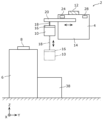
- FIG. 1 is a diagram showing an overview of a wireless communication system according to an embodiment
- 1 is a schematic diagram for explaining the transfer of a FOUP in a wireless communication system according to an embodiment.
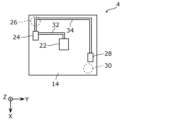
- FIG. 4 is a schematic diagram for explaining the positional relationship between a control unit, a first communication unit, and a second communication unit in the transport vehicle according to the embodiment.
- FIG. 1 is a block diagram showing a functional configuration of a wireless communication system according to an embodiment.
- 10 is a sequence diagram showing the flow of operations of the wireless communication system according to the embodiment when no failure occurs in wireless communication between a first communication unit and a communication device.
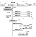
- FIG. 10 is a sequence diagram showing the flow of operations of a wireless communication system according to an embodiment when a failure occurs in wireless communication between a first communication unit and a communication device.
- Fig. 1 is a diagram showing an overview of the wireless communication system 2 according to an embodiment.
- Fig. 2 is a schematic diagram for explaining the transfer of a FOUP 10 in the wireless communication system 2 according to an embodiment.
- Fig. 3 is a schematic diagram for explaining the positional relationship between a control unit 22, a first communication unit 24, and a second communication unit 28 in a transporting platform 4 according to an embodiment.
- the wireless communication system 2 is a system constructed, for example, in a semiconductor manufacturing factory.
- the wireless communication system 2 includes a transport cart 4 (an example of a moving object), a semiconductor manufacturing device 6, and a communication device 8.
- the transport cart 4 is an overhead transport cart for transporting FOUPs 10 (an example of an item) that store semiconductor wafers, and is a so-called overhead hoist transfer (OHT).
- the transport cart 4 runs unmanned along a track 12 installed on the ceiling of the semiconductor manufacturing factory. Note that multiple transport carts 4 (e.g., several hundred) are installed in the semiconductor manufacturing factory, but for the sake of explanation, only one transport cart 4 is shown in FIG. 1.
- the transport cart 4 has a cart body 14, a gripping part 16, a lifting mechanism 18, and a lateral mechanism 20.
- the cart body 14 is configured as a hollow, approximately rectangular shape when viewed in the XY plane, and travels along the track 12.
- a FOUP 10 can be stored inside the cart body 14.
- the gripper 16 is mounted inside the cart body 14.
- the gripper 16 holds the FOUP 10 by suspending it by gripping the upper end of the FOUP 10.
- the lifting mechanism 18 is mounted inside the cart body 14.
- the lifting mechanism 18 is a mechanism for raising and lowering the gripping part 16 in the vertical direction (Z-axis direction), and is made of, for example, metal.
- the transport cart 4 when transferring a FOUP 10 between the transport cart 4 and a loading port 38 (described later) of the semiconductor manufacturing device 6, the transport cart 4 first stops at a position directly above the loading port 38. In this state, the lateral mechanism 20 slides from the storage position to the protruding position, and then the lifting mechanism 18 lowers the gripper 16 from the transport cart 4 to the vicinity of the loading port 38, and transfers the FOUP 10 between the gripper 16 and the loading port 38. Specifically, the FOUP 10 placed on the loading port 38 is gripped by the gripper 16, or the FOUP 10 is unloaded from the gripper 16 to the loading port 38. Thereafter, when the transfer of the FOUP 10 is completed, the lifting mechanism 18 raises the gripper 16 from the vicinity of the loading port 38 to the transport cart 4, and then the lateral mechanism 20 slides from the protruding position to the storage position.
- the transport cart 4 further includes a control unit 22, a first communication unit 24 (an example of a specific communication unit), a first antenna 26, a second communication unit 28 (an example of one or more other communication units), and a second antenna 30.
- the control unit 22 is mounted inside the cart body 14 and provides overall control over the operation of each part of the transport cart 4.
- the first communication unit 24 is communicatively connected (wired) to the control unit 22 via a serial cable 32.
- the first communication unit 24 transmits and receives information to and from the control unit 22 by serial communication using the serial cable 32, for example, a communication method such as RS-232C.
- the first communication unit 24 also transmits and receives information to and from the communication device 8 by wireless communication using a specified channel (frequency band).
- the first communication unit 24 transmits and receives information to and from the communication device 8 by short-range wireless communication.
- the short-range wireless communication is, for example, wireless communication using BLE (Bluetooth (registered trademark) Low Energy) or the like.
- the first antenna 26 is an antenna for the first communication unit 24 and is communicatively connected to the first communication unit 24 via a cable (not shown).
- the second communication unit 28 is communicatively connected to the first communication unit 24 via a serial cable 34 (an example of a communication cable).
- the second communication unit 28 transmits and receives information to and from the first communication unit 24 by serial communication using the serial cable 34, for example, a communication method such as RS-232C.
- the second communication unit 28 also transmits and receives information regarding the wireless communication performed by the first communication unit 24 with the communication device 8 through the serial cable 34 with the first communication unit 24. That is, the first communication unit 24 and the second communication unit 28 share information regarding the wireless communication performed by both of them with the communication device 8.
- the second communication unit 28 also transmits and receives information by wireless communication with the communication device 8 using the above-mentioned specified channel.
- the first communication unit 24 and the second communication unit 28 perform wireless communication with the communication device 8 using the same specified channel.
- the first communication unit 24 and the second communication unit 28 transmit and receive information with the communication device 8 by short-range wireless communication. Also, as shown in FIG. 3, the first communication unit 24 and the second communication unit 28 are positioned at a predetermined distance from each other.
- the second antenna 30 is an antenna for the second communication unit 28, and is communicatively connected to the second communication unit 28 via a cable (not shown). As shown in FIG. 3, the first antenna 26 and the second antenna 30 are diagonally arranged on the trolley body 14, for example, when viewed in the XY plane.
- the semiconductor manufacturing equipment 6 is a device for processing or temporarily storing semiconductor wafers stored in the FOUP 10, and is installed directly below the track 12.
- the semiconductor manufacturing equipment 6 has a loading/unloading opening 36 for loading and unloading the FOUP 10, and a loading port 38 (an example of a transfer device) located near the loading/unloading opening 36.
- the loading port 38 is a load port for loading the FOUP 10.
- the loading port 38 transfers the FOUP 10 between the gripping part 16 of the transport cart 4, and also delivers the FOUP 10 to and from the semiconductor manufacturing equipment 6 through the loading/unloading opening 36.
- FIG. 1 illustrates only one semiconductor manufacturing device 6.
- the semiconductor manufacturing device 6 has one loading port 38, but is not limited to this and may have multiple loading ports 38.
- the communication device 8 is a communication device that mediates communication between the transport cart 4 and the loading port 38 of the semiconductor manufacturing equipment 6.
- the communication device 8 is placed, for example, on the top surface of the semiconductor manufacturing equipment 6, and is communicatively connected to the loading port 38 of the semiconductor manufacturing equipment 6 via a parallel cable 40. This allows the communication device 8 to send and receive information between the loading port 38 of the semiconductor manufacturing equipment 6.
- the SEMI E84 communication sequence is applied to communication between the communication device 8 and the transport cart 4. Note that a semiconductor manufacturing factory is equipped with the same number of communication devices 8 as the loading ports 38, but for convenience of explanation, only one communication device 8 is shown in FIG. 1.
- the E84 communication sequence employs an interlock sequence consisting of multiple steps, in which the process does not proceed to the next step unless a specific control signal is turned off when the FOUP 10 is transferred between the transport cart 4 and the loading port 38.
- Fig. 4 is a block diagram showing the functional configuration of the wireless communication system 2 according to the embodiment.
- the transport cart 4 has a control unit 22, a first communication unit 24, and a second communication unit 28.
- the control unit 22 executes various processes by controlling the first communication unit 24. For example, when the transport cart 4 arrives at a position directly above the loading port 38 to which the FOUP 10 (see FIG. 1) is to be transferred, the control unit 22 instructs the first communication unit 24 to start wireless communication with the communication device 8.
- the control unit 22 is realized, for example, by a processor reading and executing a software program recorded on a recording medium such as a hard disk or semiconductor memory.
- the first communication unit 24 transmits and receives information to and from the control unit 22 via a serial cable 32 (see FIG. 3).
- the first communication unit 24 also transmits and receives information to and from the communication device 8 via wireless communication using the above-mentioned specific channel. Furthermore, if a failure occurs in the wireless communication between the first communication unit 24 and the communication device 8, the first communication unit 24 ends the wireless communication with the communication device 8 and instructs the second communication unit 28 to start wireless communication with the communication device 8.
- the second communication unit 28 transmits and receives information to and from the first communication unit 24 via the serial cable 34 (see FIG. 3).
- the second communication unit 28 also transmits and receives information to and from the control unit 22 via the serial cable 34, the first communication unit 24, and the serial cable 32. If a failure occurs in the wireless communication between the first communication unit 24 and the communication device 8, the second communication unit 28 starts wireless communication with the communication device 8 using the above-mentioned specified channel based on an instruction from the first communication unit 24. In other words, while one of the first communication unit 24 and the second communication unit 28 is performing wireless communication with the communication device 8, the other one does not perform wireless communication with the communication device 8.
- the loading port 38 of the semiconductor manufacturing device 6 has a communication unit 42 and a control unit 44.
- the communication unit 42 transmits and receives information to and from the communication device 8 via the parallel cable 40 (see Figure 1).
- the control unit 44 controls the communication unit 42 to execute various processes. Specifically, the control unit 44 executes an interlock process using an E84 communication sequence to transfer the FOUP 10 to and from the transport cart 4. The control unit 44 also executes a process to transfer the FOUP 10 to and from the semiconductor manufacturing equipment 6 through the loading/unloading port 36 (see FIG. 1).
- the control unit 44 is realized, for example, by a processor reading and executing a software program recorded on a recording medium such as a hard disk or semiconductor memory.
- the communication device 8 has a communication unit 46 and a control unit 48.
- the communication unit 46 transmits and receives information to and from the loading port 38 via the parallel cable 40.
- the communication unit 46 also transmits and receives information to and from the transport cart 4 via wireless communication.
- the control unit 48 executes various processes by controlling the communication unit 46.
- the control unit 48 is realized, for example, by a processor reading and executing a software program recorded on a recording medium such as a hard disk or semiconductor memory.
- FIG. 5 is a sequence diagram showing the flow of operation of the wireless communication system 2 according to the embodiment in a case where no failure occurs in wireless communication between the first communication unit 24 and the communication device 8.
- the control unit 22 of the transport cart 4 transmits information on the wireless communication settings between the first communication unit 24 and the communication device 8 (an example of information on wireless communication between the first communication unit 24 and the communication device 8) to the first communication unit 24 via the serial cable 32 (S101).
- the first communication unit 24 receives information on the wireless communication settings from the control unit 22 of the transport cart 4.
- the information on the wireless communication settings includes, for example, (a) the address (unique identifier such as ID) of the communication device 8 to be connected, (b) the channel used for wireless communication, and (c) the transmission output value.
- the second communication unit 28 shares information on the wireless communication settings with the first communication unit 24 via the serial cable 34.
- the control unit 22 of the transport cart 4 may transmit data to be transmitted to the communication device 8 (for example, a control signal used in the E84 communication sequence) to the first communication unit 24 together with information on the wireless communication settings.
- control unit 22 of the transport cart 4 instructs the first communication unit 24 to start wireless communication with the communication device 8 (S102).
- the first communication unit 24 of the transport cart 4 transmits information for establishing wireless communication with the communication device 8 to the communication device 8 based on instructions from the control unit 22 (S103).
- the communication device 8 can receive information from the first communication unit 24 of the transport cart 4. Next, the communication device 8 transmits a response to the information to the first communication unit 24 (S104).
- wireless communication is established between the first communication unit 24 and the communication device 8, and the first communication unit 24 executes communication with the communication device 8 for interlock processing using the E84 communication sequence (S105).
- FIG. 6 is a sequence diagram showing the flow of operation of the wireless communication system 2 according to the embodiment when a failure occurs in wireless communication between the first communication unit 24 and the communication device 8.
- steps S201 and S202 are executed in the same manner as steps S101 and S102 in the sequence diagram shown in FIG. 5.
- the first communication unit 24 of the transport cart 4 transmits information for establishing wireless communication with the communication device 8 to the communication device 8 based on an instruction from the control unit 22 (S203). At this time, because a failure has occurred in the wireless communication between the first communication unit 24 and the communication device 8, the communication device 8 cannot receive information from the first communication unit 24 of the transport cart 4.
- a possible cause of a failure in wireless communication between the first communication unit 24 and the communication device 8 is that the lateral mechanism 20, which has slid from the stored position to the protruding position, physically blocks the wireless communication path between the first communication unit 24 and the communication device 8.
- the first communication unit 24 of the transport cart 4 retries sending information to the communication device 8 multiple times until a response is received from the communication device 8 (S204, S205).
- the communication device 8 If the communication device 8 is fortunate enough to receive information from the first communication unit 24 of the transport cart 4, it will send a response to that information to the first communication unit 24. However, even in this case, due to a failure in the wireless communication between the first communication unit 24 and the communication device 8, the radio wave strength of the response from the communication device 8 will be extremely low (for example, -80 dBm or less), and the first communication unit 24 will ignore the response from the communication device 8.
- the first communication unit 24 of the transport cart 4 If the first communication unit 24 of the transport cart 4 does not receive a response from the communication device 8 even after a predetermined time has elapsed since the first transmission of information to the communication device 8 (i.e., if a wireless communication timeout occurs), the first communication unit 24 of the transport cart 4 stops wireless communication with the communication device 8 (S206).
- the first communication unit 24 of the transport cart 4 instructs the second communication unit 28 to start wireless communication with the communication device 8 (S207).
- the first communication unit 24 transmits information about wireless communication settings to the second communication unit 28 via the serial cable 34.
- the content of the instruction from the first communication unit 24 to the second communication unit 28 to start wireless communication may include information about the most recent wireless communication that the first communication unit 24 performed with the communication device 8. This information is, for example, transmitted information about the communication data that was performed up until that point (for example, a sequence number indicated in a packet, etc.).
- the second communication unit 28 transmits information for establishing wireless communication with the communication device 8 to the communication device 8 based on the instruction from the first communication unit 24 (S208).
- the communication device 8 can receive information from the second communication unit 28 of the transport cart 4. Next, the communication device 8 transmits a response to the information to the second communication unit 28 (S209).
- wireless communication is established between the second communication unit 28 and the communication device 8, and the second communication unit 28 transmits information indicating this to the first communication unit 24 (S210), and executes communication with the communication device 8 for interlock processing using the E84 communication sequence (S211).
- the first communication unit 24 may hand over the wireless communication to the second communication unit 28. This allows the second communication unit 28 to take over wireless communication with the communication device 8.
- FIG. 7 is a sequence diagram showing the flow of operation of the wireless communication system 2 according to the embodiment when a failure occurs in the wireless communication between the first communication unit 24 and the communication device 8, and in the wireless communication between the second communication unit 28 and the communication device 8.
- steps S301 and S302 are executed in the same manner as steps S101 and S201 in the sequence diagram shown in FIG. 5.
- the first communication unit 24 of the transport cart 4 transmits information for establishing wireless communication with the communication device 8 to the communication device 8 based on an instruction from the control unit 22 (S303). At this time, because a failure has occurred in the wireless communication between the first communication unit 24 and the communication device 8, the communication device 8 cannot receive information from the first communication unit 24 of the transport cart 4.
- the first communication unit 24 of the transport cart 4 retries sending information to the communication device 8 multiple times until a response is received from the communication device 8 (S304, S305).
- the communication device 8 If the communication device 8 is fortunate enough to receive information from the first communication unit 24 of the transport cart 4, it will send a response to that information to the first communication unit 24. However, even in this case, due to a failure in wireless communication between the first communication unit 24 and the communication device 8, the radio wave strength of the response from the communication device 8 will be extremely weak, and the first communication unit 24 will ignore the response from the communication device 8.
- the first communication unit 24 of the transport cart 4 If the first communication unit 24 of the transport cart 4 does not receive a response from the communication device 8 even after a predetermined time has elapsed since the first transmission of information to the communication device 8, the first communication unit 24 stops wireless communication with the communication device 8 (S306).
- the first communication unit 24 of the transport cart 4 instructs the second communication unit 28 to start wireless communication with the communication device 8 (S307). At this time, the first communication unit 24 transmits information about the wireless communication settings to the second communication unit 28 via the serial cable 34.
- the second communication unit 28 of the transport cart 4 transmits information for establishing wireless communication with the communication device 8 to the communication device 8 based on the instruction from the first communication unit 24 (S308). At this time, since a failure has occurred in the wireless communication between the second communication unit 28 and the communication device 8, the communication device 8 cannot receive information from the second communication unit 28 of the transport cart 4.
- the second communication unit 28 of the transport cart 4 retries sending information to the communication device 8 multiple times until a response is received from the communication device 8 (S309, S310).
- the first communication unit 24 of the transport cart 4 instructs the second communication unit 28 to end wireless communication with the communication device 8 (S311).
- the second communication unit 28 may respond to the first communication unit 24 with information regarding the immediately previous wireless communication that was being conducted with the communication device 8.
- the first communication unit 24 of the transport cart 4 resumes wireless communication with the communication device 8 (S312) and transmits information for establishing wireless communication with the communication device 8 to the communication device 8 based on an instruction from the control unit 22 (S313).
- the communication device 8 can receive information from the first communication unit 24.
- the communication device 8 transmits a response to the information to the first communication unit 24 (S314).
- wireless communication is established between the first communication unit 24 and the communication device 8, and the first communication unit 24 executes communication with the communication device 8 for interlock processing using the E84 communication sequence (S315).
- first communication unit 24 and the second communication unit 28 are arranged at a distance greater than a predetermined distance from each other. As a result, if a wireless communication failure occurs between the first communication unit 24 and the communication device 8, for example because the wireless communication path between the two is physically blocked by an obstacle, the second communication unit 28 can be used to increase the likelihood of successful wireless communication with the communication device 8.
- the wireless communication system of the present invention has been described based on the above embodiment, the present invention is not limited to the above embodiment.
- the present invention also includes modifications that a person skilled in the art can make to the above embodiment, and other modifications that can be realized by arbitrarily combining the components of the above embodiment.
- the control unit 22 of the transport cart 4 instructs the first communication unit 24 to start wireless communication with the communication device 8, but this is not limited to the above.
- the control unit 22 of the transport cart 4 may use the second communication unit 28 as a main unit and instruct the second communication unit 28 to start wireless communication with the communication device 8.
- the control unit 22 transmits information regarding the wireless communication settings between the second communication unit 28 and the communication device 8 to the second communication unit 28 via the serial cable 32, the first communication unit 24, and the serial cable 34.
- control unit 22 may determine, depending on the location to which the FOUP 10 is transferred, whether the first communication unit 24 or the second communication unit 28 is the communication unit that will first communicate wirelessly with the communication device 8.
- the transport cart 4 has two communication units (first communication unit 24 and second communication unit 28), but this is not limited to this, and it may have three or more communication units.
- control unit 22 and the first communication unit 24 are connected by wire, and the first communication unit 24 and the second communication unit 28 are connected by wire, but this is not limited to the above.
- each of the first communication unit 24 and the second communication unit 28 may be directly connected by wire to the control unit 22.
- the moving body is applied to a transport cart, but this is not limited, and the moving body may be applied to, for example, an unmanned transport vehicle that travels on the ground.
- each component may be configured with dedicated hardware, or may be realized by executing a software program suitable for each component.
- Each component may be realized by a program execution unit such as a CPU or processor reading and executing a software program recorded on a recording medium such as a hard disk or semiconductor memory.
- the wireless communication system according to the present invention can be applied to, for example, a semiconductor manufacturing system for transporting FOUPs using a transport cart that runs along a track installed on the ceiling.
- Wireless communication system 4 Wireless communication system 4 Transport cart 6 Semiconductor manufacturing device 8 Communication device 10 FOUP 12 Track 14 Carriage body 16 Grip unit 18 Lifting mechanism 20 Lateral mechanism 22, 44, 48 Control unit 24 First communication unit 26 First antenna 28 Second communication unit 30 Second antenna 32, 34 Serial cable 36 Loading/unloading port 38 Placement port 40 Parallel cable 42, 46 Communication unit
Landscapes
- Engineering & Computer Science (AREA)
- Computer Networks & Wireless Communication (AREA)
- Signal Processing (AREA)
- Control Of Position, Course, Altitude, Or Attitude Of Moving Bodies (AREA)
- Cable Transmission Systems, Equalization Of Radio And Reduction Of Echo (AREA)
Abstract
Description
[1.無線通信システムの概要]
まず、図1~図3を参照しながら、実施の形態に係る無線通信システム2の概要について説明する。図1は、実施の形態に係る無線通信システム2の概要を示す図である。図2は、実施の形態に係る無線通信システム2におけるFOUP10の移載を説明するための概略図である。図3は、実施の形態に係る搬送台車4における制御部22、第1の通信ユニット24及び第2の通信ユニット28の位置関係を説明するための概略図である。
図4を参照しながら、実施の形態に係る無線通信システム2の機能構成について説明する。図4は、実施の形態に係る無線通信システム2の機能構成を示すブロック図である。
図5を参照しながら、第1の通信ユニット24と通信デバイス8との無線通信に障害が発生しない場合における、無線通信システム2の動作について説明する。図5は、第1の通信ユニット24と通信デバイス8との無線通信に障害が発生しない場合における、実施の形態に係る無線通信システム2の動作の流れを示すシーケンス図である。
本実施の形態では、上述したように、第1の通信ユニット24と第2の通信ユニット28との間で無線通信に関する情報を共有しており、また、第1の通信ユニット24及び第2の通信ユニット28の各々と通信デバイス8との無線通信には同じ所定のチャンネルが用いられる。これにより、第1の通信ユニット24と通信デバイス8との無線通信に障害が発生した場合であっても、第2の通信ユニット28は、通信デバイス8との無線通信を早期に開始することができる。
以上、本発明の無線通信システムについて、上記実施の形態に基づいて説明したが、本発明は、上記実施の形態に限定されるものではない。上記実施の形態に対して当業者が思い付く変形を施して得られる形態、及び、上記実施の形態における構成要素を任意に組み合わせて実現される別の形態も本発明に含まれる。
4 搬送台車
6 半導体製造装置
8 通信デバイス
10 FOUP
12 軌道
14 台車本体
16 把持部
18 昇降機構
20 ラテラル機構
22,44,48 制御部
24 第1の通信ユニット
26 第1のアンテナ
28 第2の通信ユニット
30 第2のアンテナ
32,34 シリアルケーブル
36 搬入出口
38 載置ポート
40 パラレルケーブル
42,46 通信部
Claims (8)
- 軌道に沿って走行し且つ物品を搬送する搬送台車と、前記搬送台車との間で前記物品が移載される移載装置に通信可能に接続され且つ前記搬送台車との間で無線通信を行う通信デバイスと、を備えた無線通信システムであって、
前記搬送台車は、
互いに所定の距離以上離れて配置され、且つ、互いに通信ケーブルを介して通信可能に接続された複数の通信ユニットを有し、
前記複数の通信ユニットのうち特定の通信ユニットは、所定のチャンネルを用いて前記通信デバイスと無線通信を行い、
前記複数の通信ユニットのうち前記特定の通信ユニット以外の他の1以上の通信ユニットは、前記通信ケーブルを介して、前記特定の通信ユニットと前記通信デバイスとの無線通信に関する情報を前記特定の通信ユニットとの間で共有し、
前記特定の通信ユニットと前記通信デバイスとの無線通信に障害が発生した場合に、前記他の1以上の通信ユニットは、前記所定のチャンネルを用いて前記通信デバイスとの無線通信を開始する
無線通信システム。 - 前記特定の通信ユニットと前記通信デバイスとの無線通信に障害が発生した場合に、前記特定の通信ユニットは、当該無線通信を前記他の1以上の通信ユニットに引き継ぐ
請求項1に記載の無線通信システム。 - 前記無線通信に関する情報は、前記特定の通信ユニットと前記通信デバイスとの無線通信設定を含む
請求項1に記載の無線通信システム。 - 前記搬送台車は、さらに、
当該搬送台車を制御する制御部を有し、
前記特定の通信ユニットは、前記制御部と通信可能に有線接続され、且つ、前記制御部との間で情報を送受信し、
前記他の1以上の通信ユニットは、前記通信ケーブル及び前記特定の通信ユニットを介して、前記制御部との間で情報を送受信する
請求項1に記載の無線通信システム。 - 前記通信ケーブルは、シリアルケーブルであり、
前記他の1以上の通信ユニットは、前記シリアルケーブルを用いたシリアル通信により、前記無線通信に関する情報を前記特定の通信ユニットとの間で共有する
請求項1~4のいずれか1項に記載の無線通信システム。 - 前記搬送台車は、さらに、
前記物品を移載する場所に応じて、前記複数の通信ユニットの中から、前記通信デバイスと無線通信を行う前記特定の通信ユニットを決定する制御部を有する
請求項1に記載の無線通信システム。 - 軌道に沿って走行し且つ物品を搬送する搬送台車であって、
前記搬送台車は、
互いに所定の距離以上離れて配置され、且つ、互いに通信ケーブルを介して通信可能に接続された複数の通信ユニットを有し、
前記複数の通信ユニットのうち特定の通信ユニットは、所定のチャンネルを用いて、前記搬送台車との間で前記物品が移載される移載装置に通信可能に接続された通信デバイスと無線通信を行い、
前記複数の通信ユニットのうち前記特定の通信ユニット以外の他の1以上の通信ユニットは、前記通信ケーブルを介して、前記特定の通信ユニットと前記通信デバイスとの無線通信に関する情報を前記特定の通信ユニットとの間で共有し、
前記特定の通信ユニットと前記通信デバイスとの無線通信に障害が発生した場合に、前記他の1以上の通信ユニットは、前記所定のチャンネルを用いて前記通信デバイスとの無線通信を開始する
搬送台車。 - 物品を搬送する移動体と、前記移動体との間で前記物品が移載される移載装置に通信可能に接続され且つ前記移動体との間で無線通信を行う通信デバイスと、を備えた無線通信システムにおける制御方法であって、
前記移動体は、
互いに所定の距離以上離れて配置され、且つ、互いに通信ケーブルを介して通信可能に接続された複数の通信ユニットを有し、
前記制御方法は、
前記複数の通信ユニットのうち特定の通信ユニットが、所定のチャンネルを用いて前記通信デバイスと無線通信を行うステップと、
前記複数の通信ユニットのうち前記特定の通信ユニット以外の他の1以上の通信ユニットが、前記通信ケーブルを介して、前記特定の通信ユニットと前記通信デバイスとの無線通信に関する情報を前記特定の通信ユニットとの間で共有するステップと、
前記特定の通信ユニットと前記通信デバイスとの無線通信に障害が発生した場合に、前記他の1以上の通信ユニットが、前記所定のチャンネルを用いて前記通信デバイスとの無線通信を開始するステップと、を含む
制御方法。
Priority Applications (3)
| Application Number | Priority Date | Filing Date | Title |
|---|---|---|---|
| CN202480038284.5A CN121359499A (zh) | 2023-07-05 | 2024-04-11 | 无线通信系统、输送台车以及控制方法 |
| JP2025530983A JPWO2025009244A1 (ja) | 2023-07-05 | 2024-04-11 | |
| KR1020257040387A KR20260005382A (ko) | 2023-07-05 | 2024-04-11 | 무선 통신 시스템, 반송 대차 및 제어 방법 |
Applications Claiming Priority (2)
| Application Number | Priority Date | Filing Date | Title |
|---|---|---|---|
| JP2023-110518 | 2023-07-05 | ||
| JP2023110518 | 2023-07-05 |
Publications (1)
| Publication Number | Publication Date |
|---|---|
| WO2025009244A1 true WO2025009244A1 (ja) | 2025-01-09 |
Family
ID=94171686
Family Applications (1)
| Application Number | Title | Priority Date | Filing Date |
|---|---|---|---|
| PCT/JP2024/014741 Ceased WO2025009244A1 (ja) | 2023-07-05 | 2024-04-11 | 無線通信システム、搬送台車及び制御方法 |
Country Status (5)
| Country | Link |
|---|---|
| JP (1) | JPWO2025009244A1 (ja) |
| KR (1) | KR20260005382A (ja) |
| CN (1) | CN121359499A (ja) |
| TW (1) | TW202504374A (ja) |
| WO (1) | WO2025009244A1 (ja) |
Citations (3)
| Publication number | Priority date | Publication date | Assignee | Title |
|---|---|---|---|---|
| JP2005151488A (ja) * | 2003-11-20 | 2005-06-09 | Hitachi Kokusai Electric Inc | 無線通信システム |
| JP2013013151A (ja) * | 2012-10-15 | 2013-01-17 | Toshiba Corp | 無線通信装置及び無線通信方法 |
| WO2023074291A1 (ja) * | 2021-10-29 | 2023-05-04 | 村田機械株式会社 | 無線通信システム、搬送台車側の通信デバイス、及び通信方法 |
Family Cites Families (1)
| Publication number | Priority date | Publication date | Assignee | Title |
|---|---|---|---|---|
| JP2019036816A (ja) | 2017-08-14 | 2019-03-07 | Kyb株式会社 | 無線センサーネットワーク |
-
2024
- 2024-04-11 CN CN202480038284.5A patent/CN121359499A/zh active Pending
- 2024-04-11 JP JP2025530983A patent/JPWO2025009244A1/ja active Pending
- 2024-04-11 KR KR1020257040387A patent/KR20260005382A/ko active Pending
- 2024-04-11 TW TW113113503A patent/TW202504374A/zh unknown
- 2024-04-11 WO PCT/JP2024/014741 patent/WO2025009244A1/ja not_active Ceased
Patent Citations (3)
| Publication number | Priority date | Publication date | Assignee | Title |
|---|---|---|---|---|
| JP2005151488A (ja) * | 2003-11-20 | 2005-06-09 | Hitachi Kokusai Electric Inc | 無線通信システム |
| JP2013013151A (ja) * | 2012-10-15 | 2013-01-17 | Toshiba Corp | 無線通信装置及び無線通信方法 |
| WO2023074291A1 (ja) * | 2021-10-29 | 2023-05-04 | 村田機械株式会社 | 無線通信システム、搬送台車側の通信デバイス、及び通信方法 |
Also Published As
| Publication number | Publication date |
|---|---|
| KR20260005382A (ko) | 2026-01-09 |
| JPWO2025009244A1 (ja) | 2025-01-09 |
| CN121359499A (zh) | 2026-01-16 |
| TW202504374A (zh) | 2025-01-16 |
Similar Documents
| Publication | Publication Date | Title |
|---|---|---|
| JP6642577B2 (ja) | 搬送システム | |
| JP7496578B2 (ja) | 無線通信システム、搬送台車側の通信デバイス、及び通信方法 | |
| JP2010184760A (ja) | 移載システム | |
| JP6052132B2 (ja) | 通信デバイス及びその制御方法 | |
| JP6854498B2 (ja) | 搬送システムの制御方法、搬送システム及び管理装置 | |
| KR20150052204A (ko) | 통신 디바이스와 통신 기기 및 통신 시스템 | |
| EP3805890B1 (en) | Conveyance system | |
| EP3859771B1 (en) | Control method, transport system, and communication device | |
| WO2022190710A1 (ja) | 無線通信システム及び無線通信システムの制御方法 | |
| TWI788576B (zh) | 通訊方法、搬運系統及通訊元件 | |
| WO2025009244A1 (ja) | 無線通信システム、搬送台車及び制御方法 | |
| JP6712036B2 (ja) | 通信装置、バッファ装置、移載システム、及び、通信装置の制御方法 | |
| TW202446692A (zh) | 物品搬送設備 | |
| JP7648076B2 (ja) | 通信システム及び通信方法 | |
| US12325595B2 (en) | Article transport facility | |
| US20240375882A1 (en) | Article Transport Facility |
Legal Events
| Date | Code | Title | Description |
|---|---|---|---|
| 121 | Ep: the epo has been informed by wipo that ep was designated in this application |
Ref document number: 24835766 Country of ref document: EP Kind code of ref document: A1 |
|
| ENP | Entry into the national phase |
Ref document number: 2025530983 Country of ref document: JP Kind code of ref document: A |
|
| WWE | Wipo information: entry into national phase |
Ref document number: 2025530983 Country of ref document: JP |
|
| ENP | Entry into the national phase |
Ref document number: 1020257040387 Country of ref document: KR Free format text: ST27 STATUS EVENT CODE: A-0-1-A10-A15-NAP-PA0105 (AS PROVIDED BY THE NATIONAL OFFICE) |
|
| WWE | Wipo information: entry into national phase |
Ref document number: 1020257040387 Country of ref document: KR |
|
| WWP | Wipo information: published in national office |
Ref document number: 1020257040387 Country of ref document: KR |