WO2025009206A1 - 射出成形装置用スクリュおよび射出成形装置 - Google Patents
射出成形装置用スクリュおよび射出成形装置 Download PDFInfo
- Publication number
- WO2025009206A1 WO2025009206A1 PCT/JP2024/005054 JP2024005054W WO2025009206A1 WO 2025009206 A1 WO2025009206 A1 WO 2025009206A1 JP 2024005054 W JP2024005054 W JP 2024005054W WO 2025009206 A1 WO2025009206 A1 WO 2025009206A1
- Authority
- WO
- WIPO (PCT)
- Prior art keywords
- screw
- section
- flight
- injection molding
- groove
- Prior art date
- Legal status (The legal status is an assumption and is not a legal conclusion. Google has not performed a legal analysis and makes no representation as to the accuracy of the status listed.)
- Ceased
Links
Images


Classifications
-
- B—PERFORMING OPERATIONS; TRANSPORTING
- B29—WORKING OF PLASTICS; WORKING OF SUBSTANCES IN A PLASTIC STATE IN GENERAL
- B29C—SHAPING OR JOINING OF PLASTICS; SHAPING OF MATERIAL IN A PLASTIC STATE, NOT OTHERWISE PROVIDED FOR; AFTER-TREATMENT OF THE SHAPED PRODUCTS, e.g. REPAIRING
- B29C45/00—Injection moulding, i.e. forcing the required volume of moulding material through a nozzle into a closed mould; Apparatus therefor
- B29C45/17—Component parts, details or accessories; Auxiliary operations
- B29C45/46—Means for plasticising or homogenising the moulding material or forcing it into the mould
- B29C45/58—Details
- B29C45/60—Screws
Definitions
- the present invention relates to a screw for an injection molding device and an injection molding device.
- an injection molding device has been disclosed that has a screw that is configured with a first region in which the flight pitch, groove width, and groove depth are constant, and a second region in which the flight pitch is constant, the groove depth becomes gradually shallower, and the groove width becomes larger (Patent Document 1).
- the flight pitch at the tip is determined by the screw shape in the area that receives the raw resin. Therefore, when high pressure is applied to the resin at the tip of the screw, it is difficult to achieve a balanced control of the resin's backflow caused by this pressure.
- the present disclosure has been made to solve such problems, and has an object to provide a screw for an injection molding device that can suitably perform a desired molding.
- the screw for injection molding apparatus is a screw for use in an injection molding apparatus that receives raw material in an upstream supply section, transports the raw material to a metering section while heating it, and injects the molten raw material into a mold located downstream of the metering section.
- the screw for injection molding apparatus has a shaft that extends from the supply section to the metering section, a groove that is continuously formed in a spiral shape on the shaft, and a rib-like flight that is formed between adjacent grooves in the extension direction of the shaft.
- the width of the flight in the supply section is wider than the width of the flight in the metering section
- the pitch of the flight in the supply section is smaller than the pitch of the flight in the metering section
- the depth of the groove in the supply section is deeper than the depth of the groove in the metering section.
- the injection molding apparatus includes a heating cylinder and a screw housed in the heating cylinder so as to be rotatable and movable forward and backward.
- the injection molding apparatus kneads and plasticizes the raw material received in the supply section by rotating the screw, and injects the plasticized raw material from the metering section toward a mold by moving the screw forward and backward.
- the screw has a shaft extending from the supply section to the metering section, a groove formed in a spiral shape continuously on the shaft, and a rib-like flight formed between adjacent grooves in the extension direction of the shaft.
- the screw has a width of the flight in the supply section wider than the width of the flight in the metering section, a pitch of the flight in the supply section smaller than the pitch of the flight in the metering section, and a depth of the groove in the supply section deeper than the depth of the groove in the metering section.
- This disclosure provides a screw for an injection molding device and an injection molding device that can optimally perform the desired molding.
- FIG. 1 is an overall configuration diagram of an injection molding apparatus according to an embodiment
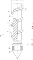
- FIG. 2 is a partially enlarged view of a screw according to an embodiment.
- FIG. 2 is an external view for explaining the shape of a screw.
- Fig. 1 is an overall configuration diagram of an injection molding apparatus 1 according to the embodiment. Note that the injection molding apparatus 1 shown in Fig. 1 is partially shown in cross section for ease of understanding.
- FIG. 1 is illustrated with a right-handed Cartesian coordinate system.
- the positive Z-axis direction coincides with the vertical upward direction.
- the XY plane coincides with the horizontal plane.
- the X-axis, Y-axis, and Z-axis directions in FIG. 1 coincide with the X-axis, Y-axis, and Z-axis directions of these Cartesian coordinate systems, respectively.
- the injection molding device 1 is used, for example, as one component of a molding system for producing a desired molded product from a raw material.
- the raw material is, for example, a resin.
- the resin may contain additives such as fibers or beads.
- the raw material may also be, for example, a metal powder other than resin.
- the injection molding device 1 is fixed onto a base 3 together with the mold clamping device 2, and is controlled to cooperate with the mold clamping device 2.
- the injection molding device 1 is connected to the mold clamping device 2 so that it can supply plasticized raw material. Note that plasticization can also be said to mean melting the raw material.
- the mold clamping device 2 holds a mold 90.
- the injection molding device 1 receives pellet-shaped raw material, plasticizes the received raw material, and injects it into the mold 90.
- the injection molding device 1 mainly comprises a cylinder 10, a hopper 20, a screw 30, a heater 40, a nozzle 50, and a drive block 60.
- the cylinder 10 is a cylindrical member that extends horizontally (in the X-axis direction).
- the cylinder 10 is connected to the hopper 20 on the upstream side (positive side of the X-axis) and receives raw materials from the hopper 20.
- the hopper 20 receives and stores the raw materials, and supplies the stored raw materials to the cylinder 10 as appropriate.
- the cylinder 10 may be referred to as a heating cylinder.
- the cylinder 10 also houses the screw 30 inside, allowing it to rotate and move forward and backward.
- the cylinder 10 is connected to a drive block 60 further upstream than the part where the hopper 20 is connected.
- the drive block 60 includes a drive device for rotating and moving the screw 30 forward and backward. By rotating, the screw 30 transports the raw materials received via the hopper 20 downstream (the negative X-axis side) while kneading them.
- the downstream tip of the cylinder 10 (the end on the negative X-axis side) becomes gradually thinner, and a nozzle 50 is formed.
- the nozzle 50 is set up so that it can inject the raw material transported to its tip by the screw 30.
- the nozzle 50 is fitted into a recess provided in the fixed platen of the mold clamping device 2.
- the screw 30 is driven by the drive block 60 to move from the upstream side to the downstream side. In this way, the injection molding device 1 pushes the raw material stored at the tip of the cylinder 10 from the nozzle 50 into the mold 90.
- the screw 30 is housed in the cylinder 10 so that it can rotate and move forward and backward along the extension direction of the cylinder 10.
- the rotational movement performed by the screw 30 here is a movement in the extension direction of the cylinder 10 (around the Y axis).
- the forward and backward movement performed by the screw 30 here is a movement from upstream to downstream (negative side of the X axis) and a movement from downstream to upstream (positive side of the X axis).
- the screw 30 is connected to the drive block 60 on the upstream side, and rotates and moves forward and backward according to the drive device of the drive block 60. As the screw 30 rotates, it transports the raw material received through the hopper 20 downstream. The screw 30 also plasticizes the raw material as it transports it.
- the screw 30 moves downstream, it pushes the raw material transported downstream of the cylinder 10 out of the injection molding device 1 through the nozzle 50. After pushing out the raw material, the screw 30 moves upstream while rotating to transport the raw material downstream. As a result, the screw 30 stores the plasticized raw material again downstream of the cylinder 10.
- the screw 30 can be divided into a supply section A1, a compression section A2, and a metering section A3 from the upstream side along the stretching direction. That is, the screw 30 receives raw material in the supply section A1 and transports the received raw material downstream.
- the compression section A2 the screw 30 compresses the raw material received from the supply section A1 to plasticize it, while transporting it to the downstream metering section A3.
- the screw 30 transports the plasticized raw material downstream of the metering section A3.
- the screw 30 further has a screw head portion A4 downstream of the metering portion A3.
- the screw head portion A4 includes a head 34 and a ring 35.
- the head 34 is a cone-shaped member provided at the tip of the screw 30.
- the head 34 approaches the nozzle 50 when the screw 30 injects the raw material. This causes the raw material stored downstream of the head 34 to be pushed out from the nozzle 50 toward the mold 90.
- the ring 35 is an annular member that suppresses the backflow of the plasticized raw material in the area provided between the head 34 and the metering portion.
- the heater 40 is a heating device provided on the outer periphery of the cylinder 10 along the extension direction of the cylinder 10.
- the heater 40 is, for example, a sheath heater or a ceramic heater.
- the heater 40 may use a heating medium such as oil.
- the heater 40 may also be divided into multiple segments along the extension direction of the cylinder 10. In this case, the heater 40 is structured such that the heating temperature can be set for each segment.
- the heater 40 may also be configured to be able to heat the nozzle 50 portion.
- the drive block 60 is connected to the screw 30 and drives the screw 30 to rotate and linearly move. Therefore, the drive block 60 has a motor for rotating the screw 30 and a motor for moving the screw 30 forward and backward.
- FIG. 2 is a partially enlarged view of the screw 30 according to the embodiment.
- the screw 30 shown in FIG. 2 is partially shown in cross section for ease of understanding.
- the screw 30 mainly comprises a shaft 31, a groove 32, a flight 33, and a head 34.
- the screw 30 also has a ring 35 adjacent to the head 34.
- the shaft 31 extends from the supply section to the metering section.
- the diameter C of the shaft 31 is set so that it operates without significant wobble relative to the inner diameter of the cylinder 10.
- a continuous spiral groove 32 is formed on the shaft 31.
- the flights 33 are rib-like portions formed between adjacent grooves 32 in the extension direction of the shaft 31.
- the depth D of the groove 32 is the depth from the outer diameter surface of the shaft 31 to the bottom surface of the groove 32.
- the width B of the flight 33 is the length of the portion corresponding to the outer diameter surface of the shaft 31 in a cross section passing through the center line of the shaft 31.
- the width B of the flight 33 can also be said to be the length of the top of the flight 33 in the extension direction of the screw 30.
- the pitch P of the flight 33 is the pitch of adjacent flights 33 in the extension direction of the screw 30.
- the pitch of the flight 33 can also be said to be the pitch of the groove 32.
- the depth D of the groove 32, the width B of the flight 33, and the pitch P of the flight 33 each have different dimensions depending on the position on the screw 30.
- angle F between the flight 33 from the supply section to the metering section of the screw 30 in this embodiment and a cross section perpendicular to the screw axis is set within the range of 16 degrees to 26 degrees.
- Figure 3 is an external view for explaining the shape of the screw.
- the screw 30 shown in Figure 3 is the part housed in the cylinder 10.
- the screw 30 is connected to the drive block 60 on the positive side of the X-axis in Figure 3.
- Figure 3 does not show the connection part with the drive block 60.
- the symbols indicating the depth, flight width, and flight pitch of the groove 32 of the screw 30 shown in Figure 3 are the same as those shown in Figure 2, but with an additional number added after the symbol. This is to indicate that the dimensions of each part differ depending on the position, and therefore each part has different dimensions at each position.
- the groove 32 in the supply section A1 has a depth D1
- the groove 32 in the metering section A1 has a depth D3.
- the width B1 of the flight 33 in the supply section A1 is wider than the width B3 of the flight in the metering section A3.
- the width B3 of the flight 33 in the metering section A3 is narrower than the width B1 of the flight in the supply section A1.
- the width B3 of the flight 33 in the metering section A3 is 27 percent to 60 percent of the width B1 of the flight 33 in the supply section A1.
- the pitch P1 of the flights 33 in the supply section A1 is smaller than the pitch P3 of the flights 33 in the weighing section A3.
- the pitch P3 of the flight 33 in the metering section A3 is 110 percent to 170 percent of the pitch P1 of the flight 33 in the supply section A1.
- the depth D1 of the groove 32 in the supply section A1 is deeper than the depth D3 of the groove 32 in the measuring section A3.
- the cross-sectional area (D1 x (P1 - B1)) parallel to the extension direction of the groove 32 in the supply section A1 is 100 to 150 percent of the cross-sectional area (D3 x (P3 - B3)) of the groove 32 in the metering section A3.
- the groove 32 of the screw 30 is formed in the compression section A2 so that it gradually becomes shallower from the supply section A1 toward the metering section A3. That is, in the compression section A2 shown in FIG. 3, the depth D22 of the groove 32 on the side relatively closer to the metering section A3 is shallower than the depth D21 of the groove 32 on the side relatively closer to the supply section A1.
- Flight 33 is also formed so that its width gradually narrows from the upstream side to the downstream side in compression section A2. That is, for example, downstream width B22 in compression section A2 is narrower than upstream width B21.
- the flights are formed so that the pitch gradually widens from the upstream side to the downstream side in the compression section. That is, for example, the downstream pitch P22 in compression section A2 is wider than the upstream pitch P21.
- the screw 30 has been described above. As mentioned above, the width B and pitch P of the flight 33 in the screw 30 change along the extension direction. Furthermore, the depth D of the groove 32 in the screw 30 can also change along the extension direction. Therefore, the shape and cross-sectional area of the groove 32 in the screw 30 are set by the three parameters of the width B of the flight 33, the pitch P, and the depth D of the groove 32.
- the compression ratio (S1/S2) which is the ratio of the cross-sectional area S1 of the groove 32 in the supply section A1 to the cross-sectional area S2 of the groove 32 in the metering section A3, becomes higher than in the above-mentioned screw 30.
- this screw with a constant flight pitch is prone to increasing shear heat due to the high compression ratio, which makes the raw material more susceptible to deterioration.
- the screw 30 disclosed herein is capable of increasing the cross-sectional area of the groove 32 while suppressing an increase in the pitch P of the flight 33 in the metering section A3. Therefore, the screw 30 can suppress backflow of the raw material when the pressure of the raw material increases in the region from the metering section A3 to the head section A4. Alternatively, the screw 30 can suppress a decrease in the flow rate of the raw material being transported to the tip of the screw when the pressure of the raw material increases in the region from the metering section A3 to the head section A4 of the screw.
- the screw 30 can keep the compression ratio low. Therefore, the screw 30 can suppress the deterioration of the raw material. Furthermore, by performing molding at a relatively low compression ratio, the screw 30 can suppress quality deterioration such as wear and breakage of the flights.
- This disclosure can be used in inline screw type injection molding machines.
Landscapes
- Engineering & Computer Science (AREA)
- Manufacturing & Machinery (AREA)
- Mechanical Engineering (AREA)
- Injection Moulding Of Plastics Or The Like (AREA)
Abstract
射出成形装置用のスクリュ(30)は、射出成形装置に用いるためのスクリュである。スクリュ(30)は、供給部から計量部に亘り延伸する軸(31)と、軸(31)に連続して螺旋状に形成されている溝(32)と、軸(31)の延伸方向に隣接する溝(32)の間に形成されるリブ状のフライト(33)と、を有している。またこのスクリュ(30)は、供給部におけるフライト(33)の幅が計量部におけるフライト(33)の幅より広く、供給部におけるフライト(33)のピッチが計量部におけるフライト(33)のピッチより小さく、供給部における溝(32)の深さが計量部における溝(32)の深さより深い。
Description
本発明は射出成形装置用スクリュおよび射出成形装置に関する。
インラインスクリュ方式の射出成形装置において、スクリュの形状に関して様々な提案が開示されている。
例えば、フライトピッチ、溝幅、溝深さが一定の第1領域と、フライトピッチは一定で溝深さが順次浅くなり、かつ溝幅が大きくなる第2領域とで構成されているスクリュを有する射出成形装置が開示されている(特許文献1)。
しかしながら、上述の技術においては、原料樹脂を受け入れる領域のスクリュ形状により先端部のフライトピッチが決定される。そのため、スクリュ先端において樹脂に対して高い圧力を掛けた場合に、この圧力により樹脂が逆流することをバランス良く制御することが難しい。
本開示は、このような課題を解決するために成されたものであって、所望の成形を好適に行う射出成形装置用スクリュ等を提供することを目的としている。
本開示にかかる射出成形装置用スクリュは、上流側である供給部において原料を受け入れ、原料を計量部に加熱しながら搬送し、溶融した原料を計量部の下流側に設けた金型に射出する射出成形装置に用いるためのスクリュである。射出成形装置用スクリュは、供給部から計量部に亘り延伸する軸と、軸に連続して螺旋状に形成されている溝と、軸の延伸方向に隣接する溝の間に形成されるリブ状のフライトと、を有している。またこのスクリュは、供給部におけるフライトの幅が、計量部におけるフライトの幅より広く、供給部におけるフライトのピッチが、計量部におけるフライトのピッチより小さく、供給部における溝の深さが、計量部における溝の深さより深い。
本開示に係る射出成形装置は、加熱シリンダと、加熱シリンダ内に回転可能および進退可能に収容されたスクリュとを有する。射出成形装置は、スクリュを回転することにより、供給部において受け入れた原料の混練と可塑化とを行い、スクリュを進退することにより、可塑化した原料を計量部から金型に向かって射出する。上記スクリュは、供給部から計量部に亘り延伸する軸と、軸に連続して螺旋状に形成されている溝と、軸の延伸方向に隣接する溝の間に形成されるリブ状のフライトと、を有している。上記スクリュは、供給部におけるフライトの幅が、計量部におけるフライトの幅より広く、供給部におけるフライトのピッチが、計量部におけるフライトのピッチより小さく、供給部における溝の深さが、計量部における溝の深さより深い。
本開示によれば、所望の成形を好適に行う射出成形装置用スクリュおよび射出成形装置を提供できる。
以下、発明の実施の形態を通じて本発明を説明するが、特許請求の範囲にかかる発明を以下の実施形態に限定するものではない。また、実施形態で説明する構成の全てが課題を解決するための手段として必須であるとは限らない。説明の明確化のため、以下の記載および図面は、適宜、省略、および簡略化がなされている。なお、各図面において、同一の要素には同一の符号が付されており、必要に応じて重複説明は省略されている。
<実施の形態>
以下、図面を参照して本発明の実施の形態について説明する。図1は、実施の形態にかかる射出成形装置1の全体構成図である。なお、図1に示す射出成形装置1は、理解容易のため、一部が断面図として示されている。
以下、図面を参照して本発明の実施の形態について説明する。図1は、実施の形態にかかる射出成形装置1の全体構成図である。なお、図1に示す射出成形装置1は、理解容易のため、一部が断面図として示されている。
なお、構成要素の位置関係を説明するための便宜的なものとして、図1は、右手系の直交座標系が付されている。Z軸プラス方向は鉛直上向きと一致している。XY平面は水平面と一致している。また、図2以降において、直交座標系が付されている場合、図1のX軸、Y軸、およびZ軸方向と、これらの直交座標系のX軸、Y軸、およびZ軸方向はそれぞれ一致している。
射出成形装置1は例えば、原料から所望の成形品を製造するための成形システムの構成の一つとして用いられる。原料とは例えば樹脂である。樹脂は繊維やビーズなどの添加物を含んでいてもよい。また原料とは例えば樹脂以外の金属粉などであってもよい。
射出成形装置1は、型締め装置2と共に、基台3の上に固定され、型締め装置2と協働するように制御される。射出成形装置1は型締め装置2に対して可塑化した原料を供給可能に接続している。なお、可塑化とは原料を溶融させることと言い換えてもよい。型締め装置2は、金型90を保持している。射出成形装置1は、ペレット状の原料を受け入れ、受け入れた原料を可塑化して金型90に射出する。射出成形装置1は主な構成として、シリンダ10、ホッパ20、スクリュ30、ヒータ40、ノズル50および駆動ブロック60を有している。
シリンダ10は、水平方向(X軸方向)に延伸する筒状部材である。シリンダ10は、上流側(X軸プラス側)において、ホッパ20に連結し、ホッパ20から原料を受け入れる。ホッパ20は、原料を受け入れて貯留すると共に、貯留した原料を適宜、シリンダ10に供給する。なお、シリンダ10は、加熱シリンダと称され得る。
またシリンダ10は、内部にスクリュ30を回転可能および進退可能に収容している。シリンダ10は、ホッパ20が連結している部分よりもさらに上流側において駆動ブロック60に接続している。駆動ブロック60は、スクリュ30を回転および進退させるための駆動装置を含む。スクリュ30は、回転することにより、ホッパ20を介して受け入れた原料を混練しながら下流側(X軸マイナス側)へ搬送する。
シリンダ10の下流の先端部(X軸マイナス側の端部)は、段階的に細くなっており、ノズル50が形成されている。ノズル50は、スクリュ30が先端に搬送した原料を射出可能に設定されている。ノズル50は、型締め装置2の固定盤に設けられた凹部に嵌め込まれている。スクリュ30は、駆動ブロック60により駆動されて、上流側から下流側へ移動する。これにより、射出成形装置1は、シリンダ10の先端に貯留した原料をノズル50から金型90に押し出す。
スクリュ30は、シリンダ10の延伸方向に沿って回転可能および進退可能に収容されている。なお、ここでスクリュ30が行う回転動作は、シリンダ10の延伸方向(Y軸周り)に回転する動作である。またここでスクリュ30が行う進退動作は、上流から下流(X軸のマイナス側)へ向かう動作および下流から上流(X軸プラス側)へ移動する動作である。
スクリュ30は上流側において駆動ブロック60に接続し、駆動ブロック60が有する駆動装置にしたがって回転動作および進退動作を行う。スクリュ30は、スクリュ30が回転することにより、ホッパ20を介して受け入れた原料を下流側へ搬送する。またスクリュ30は、原料を搬送しながら可塑化する。
さらにスクリュ30は、スクリュ30が下流側へ移動することにより、シリンダ10の下流に搬送した原料をノズル50から射出成形装置1の外へ押し出す。なお、原料を押し出した後に、スクリュ30は回転して原料を下流へ搬送しつつ、上流へ移動する。これにより、スクリュ30は、可塑化した原料を再びシリンダ10の下流側へ貯留する。
スクリュ30は、上述の機能を実現するために、延伸方向にそって上流側から、供給部A1、圧縮部A2および計量部A3に区分けされ得る。すなわちスクリュ30は、供給部A1において、原料を受け入れ、受け入れた原料を下流側へ搬送する。圧縮部A2において、スクリュ30は、供給部A1から受け取った原料を圧縮することにより可塑化しつつ、下流の計量部A3に搬送する。計量部A3において、スクリュ30は、可塑化した原料を計量部A3の下流側に搬送する。
スクリュ30はさらに、計量部A3の下流側に、スクリュヘッド部A4を有している。スクリュヘッド部A4は、ヘッド34およびリング35を含む。ヘッド34は、スクリュ30の先端に設けられた円錐状の部材である。ヘッド34は、スクリュ30が原料を射出する際に、ノズル50に近づく。これによりヘッド34より下流側に貯留されていた原料がノズル50から金型90に向かって押し出される。リング35は、ヘッド34と計量部との間に設けられた領域において、可塑化した原料の逆流を抑制するための環状の部材である。
ヒータ40は、シリンダ10の外周において、シリンダ10の延伸方向に沿って設けられた加熱装置である。ヒータ40は例えば、シースヒータまたはセラミックヒータである。ヒータ40は、オイルなどの加熱媒体を利用したものであってもよい。またヒータ40は、シリンダ10の延伸方向に沿って複数のセグメントに分割されていてもよい。この場合、ヒータ40は、セグメントごとに加熱する温度が設定可能な構造となっている。ヒータ40は、ノズル50部分も加熱可能に構成され得る。
駆動ブロック60は、スクリュ30に接続し、スクリュ30を回転駆動するとともに、スクリュ30を直動駆動する。そのため、駆動ブロック60は、スクリュ30を回転するためのモータと、スクリュ30を進退させるためのモータと、をそれぞれ有している。
次に、図2を参照して、スクリュ30の構成についてさらに説明する。図2は、実施の形態にかかるスクリュ30の部分拡大図である。図2に示すスクリュ30は、理解容易のため、一部が断面図として示されている。スクリュ30は主な構成として、軸31、溝32、フライト33およびヘッド34を有している。またスクリュ30は、ヘッド34に隣接する部分にリング35を有している。
軸31は、供給部から計量部に亘り延伸している。軸31の直径Cは、シリンダ10の内径に対して大きなガタツキがなく動作するように設定されている。軸31には、連続して螺旋状に溝32が形成されている。フライト33は、軸31の延伸方向に隣接する溝32の間に形成されるリブ状の部分である。
ここで、溝32の深さDは、軸31の外径面から溝32の底面までの深さである。またフライト33の幅Bは、軸31の中心線を通る断面における軸31の外径面に相当する部分の長さである。フライト33の幅Bは、フライト33の頂部におけるスクリュ30の延伸方向の長さということもできる。またフライト33のピッチPは、スクリュ30の延伸方向における隣接するフライト33のピッチである。フライト33のピッチは、溝32のピッチと言い換えることも出来る。溝32の深さD、フライト33の幅Bおよびフライト33のピッチPは、スクリュ30の位置によりそれぞれ異なる寸法となっている。
なお、本実施の形態にかかるスクリュ30の供給部から計量部におけるフライト33とスクリュ軸直角断面(スクリュ30の中心軸に直交する断面)とがなす角Fは、16度から26度の範囲内に設定されている。
次に、図3を参照して、スクリュ30の各部の形状の具体的な特徴について説明する。図3は、スクリュの形状を説明するための外観図である。図3に示すスクリュ30は、シリンダ10に収容されている部分である。スクリュ30は、図3のX軸プラス側において、駆動ブロック60に接続している。ただし図3は、駆動ブロック60との接続部分を省略して示したものである。
図3に示すスクリュ30の溝32の深さ、フライトの幅およびフライトピッチをそれぞれ示す符号は、図2に示した符号の後に数字がさらに付されている。これは、各部の寸法が、位置により異なるため、この位置それぞれに異なる寸法を有することを示すためである。例えば、供給部A1における溝32は深さD1を有し、計量部A1における溝32は深さD3を有している。
上述の内容を踏まえ、図3に示すスクリュ30の形状について説明する。スクリュ30において、供給部A1のフライト33の幅B1は、計量部A3におけるフライトの幅B3より広い。換言すると、計量部A3のフライト33の幅B3は、供給部A1におけるフライトの幅B1より狭い。
より具体的には、計量部A3のフライト33の幅B3は、供給部A1のフライト33の幅B1の27パーセント~60パーセントである。
また供給部A1におけるフライト33のピッチP1は、計量部A3におけるフライト33のピッチP3より小さい。
より具体的には、計量部A3のフライト33のピッチP3は、供給部A1のフライト33のピッチP1の110パーセント~170パーセントである。
供給部A1における溝32の深さD1は、計量部A3における溝32の深さD3より深い。
あるいは、供給部A1における溝32の延伸方向に平行な断面積(D1×(P1-B1))は、計量部A3の溝32の断面積(D3×(P3-B3))の100~150パーセントである。
またスクリュ30の溝32は、圧縮部A2において、供給部A1から計量部A3に向かって徐々に浅くなるように形成されている。すなわち、図3に示す圧縮部A2において、相対的に計量部A3に近い側の溝32の深さD22は、相対的に供給部A1に近い側の溝32の深さD21より浅い。
またフライト33は、圧縮部A2において上流側から下流側に向かって徐々に幅が狭くなるように形成されている。すなわち例えば圧縮部A2における下流側の幅B22は、上流側の幅B21より狭い。
フライトは、圧縮部において上流側から下流側に向かって徐々にピッチが広くなるように形成されている。すなわち例えば圧縮部A2における下流側のピッチP22は、上流側のピッチP21より広い。
以上、スクリュ30について説明した。上述のとおり、スクリュ30におけるフライト33の幅BおよびピッチPは、延伸方向に沿って変化する。またスクリュ30は、溝32の深さDも延伸方向に沿って変化し得る。そのためスクリュ30における溝32の形状および断面積は、フライト33の幅B、ピッチPおよび溝32の深さDの3つのパラメータにより設定される。
ところで、仮に、フライト33の幅Bを一定にして、ピッチPを上流側から下流側に沿って大きくした場合は、計量部A3におけるフライト33のリード角が、上述のスクリュ30に比べると相対的に大きくなる。このフライト幅が一定のスクリュは、射出成形装置1において計量部A3よりも下流側に原料を供給する際に原料が計量部A3に逆流しやすくなる。
一方、フライト33のピッチPを一定にして、幅Bを上流側から下流側に沿って狭くした場合は、上述のスクリュ30と比べると、供給部A1の溝32の断面積S1と、計量部A3の溝32の断面積S2との比である圧縮比(S1/S2)が高くなってしまう。すなわちこのフライトピッチが一定のスクリュは、高い圧縮比により剪断熱が上昇しやすく、これに伴い原料の劣化が発生しやすくなる。
本開示にかかるスクリュ30は、上述したフライト幅が一定のスクリュと比べると、計量部A3におけるフライト33のピッチPの増加を抑えつつ、溝32の断面積を大きくすることが可能となる。そのため、スクリュ30は、計量部A3からヘッド部A4の領域で原料の圧力が高くなった場合に、原料の逆流を抑えることができる。あるいはスクリュ30は、スクリュの計量部A3からヘッド部A4の領域で原料の圧力が高くなった場合に、スクリュの先端側へ搬送する原料の流量の低下を抑制できる。
またスクリュ30は、上述したフライトピッチが一定のスクリュと比べると、圧縮比を低く抑えることができる。そのため、スクリュ30は、原料の劣化を抑制できる。また比較的に低い圧縮比による成形を行うことにより、スクリュ30は、フライトの摩耗や破損等の品質劣化を抑制できる。
以上、実施の形態によれば、所望の成形を好適に行う射出成形装置用スクリュおよび射出成形装置を提供できる。
以上、実施の形態を参照して本願発明を説明したが、本願発明は上記によって限定されるものではない。本願発明の構成や詳細には、発明のスコープ内で当業者が理解し得る様々な変更をすることができる。
本開示は、インラインスクリュ方式の射出成形装置に利用可能である。
この出願は、2023年7月6日に出願された日本出願特願2023-111086を基礎とする優先権を主張し、その開示の全てをここに取り込む。
1 射出成形装置
2 型締め装置
3 基台
10 シリンダ
20 ホッパ
30 スクリュ
31 軸
32 溝
33 フライト
34 ヘッド
35 リング
40 ヒータ
50 ノズル
60 駆動ブロック
90 金型
2 型締め装置
3 基台
10 シリンダ
20 ホッパ
30 スクリュ
31 軸
32 溝
33 フライト
34 ヘッド
35 リング
40 ヒータ
50 ノズル
60 駆動ブロック
90 金型
Claims (9)
- 上流側である供給部において原料を受け入れ、前記原料を計量部に加熱しながら搬送し、溶融した前記原料を前記計量部の下流側に設けた金型に射出する射出成形装置に用いるためのスクリュであって、
前記供給部から前記計量部に亘り延伸する軸と、
前記軸に連続して螺旋状に形成されている溝と、
前記軸の延伸方向に隣接する前記溝の間に形成されるリブ状のフライトと、
を備え、
前記供給部における前記フライトの幅は、前記計量部における前記フライトの幅より広く、
前記供給部における前記フライトのピッチは、前記計量部における前記フライトのピッチより小さく、
前記供給部における前記溝の深さは、前記計量部における前記溝の深さより深い、
射出成形装置用スクリュ。 - 前記計量部の前記フライトの幅は、前記供給部の前記フライトの幅の40パーセントである、
請求項1に記載の射出成形装置用スクリュ。 - 前記計量部の前記フライトのピッチは、前記供給部の前記フライトのピッチの140パーセントである、
請求項1に記載の射出成形装置用スクリュ。 - 前記供給部における前記溝の前記延伸方向に平行な断面積は、前記計量部の前記溝の断面積の100~150パーセントである、
請求項1~3のいずれか一項に記載の射出成形装置用スクリュ。 - 前記供給部と前記計量部との間に、圧縮部を備え、
前記溝は、前記圧縮部において前記供給部から前記計量部に向かって徐々に浅くなるように形成されている、
請求項1に記載の射出成形装置用スクリュ。 - 前記フライトは、前記圧縮部において前記上流側から前記下流側に向かって徐々に幅が狭くなるように形成されている、
請求項5に記載の射出成形装置用スクリュ。 - 前記フライトは、前記圧縮部において前記上流側から前記下流側に向かって徐々にピッチが広くなるように形成されている、
請求項5または6に記載の射出成形装置用スクリュ。 - 前記供給部から前記計量部における前記フライトとスクリュ軸直角断面とがなす角は、16度から26度の範囲内に設定されている、
請求項7に記載の射出成形装置用スクリュ。 - 加熱シリンダと、前記加熱シリンダ内に回転可能および進退可能に収容されたスクリュとを有し、前記スクリュを回転することにより、供給部において受け入れた原料の混練と可塑化とを行い、前記スクリュを進退することにより、可塑化した前記原料を計量部から金型に向かって射出する射出成形装置であって、
前記スクリュは、
前記供給部から前記計量部に亘り延伸する軸と、
前記軸に連続して螺旋状に形成されている溝と、
前記軸の延伸方向に隣接する前記溝の間に形成されるリブ状のフライトと、
を備え、
前記供給部における前記フライトの幅は、前記計量部における前記フライトの幅より広く、
前記供給部における前記フライトのピッチは、前記計量部における前記フライトのピッチより小さく、
前記供給部における前記溝の深さは、前記計量部における前記溝の深さより深い、
射出成形装置。
Priority Applications (1)
| Application Number | Priority Date | Filing Date | Title |
|---|---|---|---|
| CN202480045488.1A CN121487824A (zh) | 2023-07-06 | 2024-02-14 | 用于注射成型装置的螺杆及注射成型装置 |
Applications Claiming Priority (2)
| Application Number | Priority Date | Filing Date | Title |
|---|---|---|---|
| JP2023111086A JP2025008696A (ja) | 2023-07-06 | 2023-07-06 | 射出成形装置用スクリュおよび射出成形装置 |
| JP2023-111086 | 2023-07-06 |
Publications (1)
| Publication Number | Publication Date |
|---|---|
| WO2025009206A1 true WO2025009206A1 (ja) | 2025-01-09 |
Family
ID=94172194
Family Applications (1)
| Application Number | Title | Priority Date | Filing Date |
|---|---|---|---|
| PCT/JP2024/005054 Ceased WO2025009206A1 (ja) | 2023-07-06 | 2024-02-14 | 射出成形装置用スクリュおよび射出成形装置 |
Country Status (3)
| Country | Link |
|---|---|
| JP (1) | JP2025008696A (ja) |
| CN (1) | CN121487824A (ja) |
| WO (1) | WO2025009206A1 (ja) |
Citations (6)
| Publication number | Priority date | Publication date | Assignee | Title |
|---|---|---|---|---|
| JPH09300413A (ja) * | 1996-05-15 | 1997-11-25 | Nissei Plastics Ind Co | 射出スクリュ |
| JP2011224801A (ja) | 2010-04-15 | 2011-11-10 | Toyo Mach & Metal Co Ltd | 射出成形機 |
| JP2014156075A (ja) * | 2013-02-18 | 2014-08-28 | Japan Steel Works Ltd:The | 射出成形機用のスクリュ |
| JP2016182687A (ja) * | 2015-03-25 | 2016-10-20 | 住友重機械工業株式会社 | 射出装置、およびスクリュ |
| JP2019025851A (ja) * | 2017-08-02 | 2019-02-21 | 東芝機械株式会社 | 射出成形用スクリュ、および射出成形機 |
| JP2023111086A (ja) | 2022-01-31 | 2023-08-10 | 株式会社オービック | 設定業務支援装置、設定業務支援方法および設定業務支援プログラム |
-
2023
- 2023-07-06 JP JP2023111086A patent/JP2025008696A/ja active Pending
-
2024
- 2024-02-14 WO PCT/JP2024/005054 patent/WO2025009206A1/ja not_active Ceased
- 2024-02-14 CN CN202480045488.1A patent/CN121487824A/zh active Pending
Patent Citations (6)
| Publication number | Priority date | Publication date | Assignee | Title |
|---|---|---|---|---|
| JPH09300413A (ja) * | 1996-05-15 | 1997-11-25 | Nissei Plastics Ind Co | 射出スクリュ |
| JP2011224801A (ja) | 2010-04-15 | 2011-11-10 | Toyo Mach & Metal Co Ltd | 射出成形機 |
| JP2014156075A (ja) * | 2013-02-18 | 2014-08-28 | Japan Steel Works Ltd:The | 射出成形機用のスクリュ |
| JP2016182687A (ja) * | 2015-03-25 | 2016-10-20 | 住友重機械工業株式会社 | 射出装置、およびスクリュ |
| JP2019025851A (ja) * | 2017-08-02 | 2019-02-21 | 東芝機械株式会社 | 射出成形用スクリュ、および射出成形機 |
| JP2023111086A (ja) | 2022-01-31 | 2023-08-10 | 株式会社オービック | 設定業務支援装置、設定業務支援方法および設定業務支援プログラム |
Also Published As
| Publication number | Publication date |
|---|---|
| JP2025008696A (ja) | 2025-01-20 |
| CN121487824A (zh) | 2026-02-06 |
Similar Documents
| Publication | Publication Date | Title |
|---|---|---|
| US11691340B2 (en) | Three-dimensional modeling apparatus and three-dimensional modeling method | |
| US20170291364A1 (en) | Single screw micro-extruder for 3d printing | |
| US7918662B2 (en) | Integrated apparatus having kneading part and injecting part | |
| EP2110223A1 (en) | Screw and injection apparatus | |
| JP5846998B2 (ja) | 可塑化装置、射出装置、射出成形装置、押出機、及び成形品の製造方法 | |
| US11718006B2 (en) | Material delivery device, three-dimensional shaping device, and injection molding device | |
| JP5601871B2 (ja) | 射出成形機 | |
| WO2025009206A1 (ja) | 射出成形装置用スクリュおよび射出成形装置 | |
| JP7238533B2 (ja) | 材料供給装置、射出成形装置及び三次元造形装置 | |
| CN105751455B (zh) | 螺盘与柱塞组合式注射成型装置 | |
| CN206124181U (zh) | 一种挤塑螺杆 | |
| JP2010280128A (ja) | 混練装置および成形機 | |
| JP5779697B2 (ja) | 射出成形機 | |
| KR101015353B1 (ko) | 다단의 회전믹서를 구비한 믹싱 스크류 | |
| US11958222B2 (en) | Plasticizing device, injection molding machine, and three-dimensional shaping apparatus | |
| US20250205948A1 (en) | Backflow-preventing-mechanism-equipped screw, injection molding apparatus including the same, and backflow preventing ring | |
| JP7267386B1 (ja) | 発泡成形体製造装置及び発泡成形体製造装置用スクリュ | |
| KR20210060794A (ko) | 사출성형용 고혼련 가변 스크류 및 이를 가지는 사출성형용 혼련장치 | |
| JP7561053B2 (ja) | コルゲートホースの製造システム | |
| JP7578780B1 (ja) | スクリューヘッド構造体および射出成形機 | |
| JP2020059204A (ja) | 射出成形機 | |
| KR101583793B1 (ko) | 이방향 다축 압출기 | |
| JP6591891B2 (ja) | 射出成形品の製造方法 | |
| CN201619231U (zh) | 注塑机注塑螺杆结构 | |
| KR20130089342A (ko) | 사출성형기용 스크류 |
Legal Events
| Date | Code | Title | Description |
|---|---|---|---|
| 121 | Ep: the epo has been informed by wipo that ep was designated in this application |
Ref document number: 24835729 Country of ref document: EP Kind code of ref document: A1 |
|
| WWE | Wipo information: entry into national phase |
Ref document number: 2024835729 Country of ref document: EP |
|
| NENP | Non-entry into the national phase |
Ref country code: DE |