WO2025009151A1 - 電動駆動装置 - Google Patents
電動駆動装置 Download PDFInfo
- Publication number
- WO2025009151A1 WO2025009151A1 PCT/JP2023/025112 JP2023025112W WO2025009151A1 WO 2025009151 A1 WO2025009151 A1 WO 2025009151A1 JP 2023025112 W JP2023025112 W JP 2023025112W WO 2025009151 A1 WO2025009151 A1 WO 2025009151A1
- Authority
- WO
- WIPO (PCT)
- Prior art keywords
- rotor
- gears
- support body
- pair
- cylindrical portion
- Prior art date
- Legal status (The legal status is an assumption and is not a legal conclusion. Google has not performed a legal analysis and makes no representation as to the accuracy of the status listed.)
- Ceased
Links
Images





Classifications
-
- B—PERFORMING OPERATIONS; TRANSPORTING
- B60—VEHICLES IN GENERAL
- B60K—ARRANGEMENT OR MOUNTING OF PROPULSION UNITS OR OF TRANSMISSIONS IN VEHICLES; ARRANGEMENT OR MOUNTING OF PLURAL DIVERSE PRIME-MOVERS IN VEHICLES; AUXILIARY DRIVES FOR VEHICLES; INSTRUMENTATION OR DASHBOARDS FOR VEHICLES; ARRANGEMENTS IN CONNECTION WITH COOLING, AIR INTAKE, GAS EXHAUST OR FUEL SUPPLY OF PROPULSION UNITS IN VEHICLES
- B60K17/00—Arrangement or mounting of transmissions in vehicles
- B60K17/04—Arrangement or mounting of transmissions in vehicles characterised by arrangement, location or kind of gearing
- B60K17/12—Arrangement or mounting of transmissions in vehicles characterised by arrangement, location or kind of gearing of electric gearing
-
- F—MECHANICAL ENGINEERING; LIGHTING; HEATING; WEAPONS; BLASTING
- F16—ENGINEERING ELEMENTS AND UNITS; GENERAL MEASURES FOR PRODUCING AND MAINTAINING EFFECTIVE FUNCTIONING OF MACHINES OR INSTALLATIONS; THERMAL INSULATION IN GENERAL
- F16H—GEARING
- F16H48/00—Differential gearings
- F16H48/06—Differential gearings with gears having orbital motion
- F16H48/10—Differential gearings with gears having orbital motion with orbital spur gears
- F16H48/11—Differential gearings with gears having orbital motion with orbital spur gears having intermeshing planet gears
Definitions
- the present invention relates to an electric drive device, for example, for driving the wheels of a vehicle.
- the drive devices described in Patent Documents 1 and 2 are known as electric drive devices that drive the left and right wheels on the front or rear side of a vehicle.
- the drive devices described in Patent Documents 1 and 2 have multiple gears housed inside a rotor shaft formed into a hollow cylinder, and these multiple gears form a differential gear mechanism.
- a rotor core is fixed to the outside of the rotor shaft, and a stator core and stator windings are arranged on the outer periphery of the rotor core. When current is supplied to the stator windings, the rotor core and rotor shaft rotate, and the rotational force is distributed differentially to a pair of output shafts by the differential gear mechanism.
- Patent Document 3 The applicant has also proposed a differential device described in Patent Document 3 that allows differential distribution of the driving force of a driving source such as an engine to drive shafts connected to the left and right wheels.
- the present invention was made in consideration of these circumstances, and its purpose is to provide an electric drive device that makes it easy to assemble multiple gears and to process the members that support the multiple gears.
- the present invention provides an electric drive device comprising a pair of output shafts, a rotor having a cylindrical portion that houses the pair of output shafts, an electric motor portion arranged on the outer periphery of the cylindrical portion of the rotor, and a differential gear mechanism that distributes torque generated by the electric motor portion to the pair of output shafts, the electric motor portion having a stator having a stator core and windings and a rotor arranged inside the stator, the rotor being fixed to the outer periphery of the cylindrical portion of the rotor, the differential gear mechanism having a plurality of gears including a pair of side gears respectively connected to the pair of output shafts, and a support body that supports the plurality of gears, the rotor has a wall portion provided on the inside of the cylindrical portion integral with the cylindrical portion, the support body is arranged inside the cylindrical portion with one end face on one axial side facing the wall portion of the rotor, and rotates integrally with the rotor.
- the electric drive device makes it easy to assemble multiple gears and to process the members that support the multiple gears.
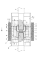
- FIG. 1 is a cross-sectional view showing an example of the configuration of an electric drive device according to a first embodiment of the present invention.
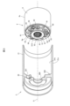
- FIG. 2 is a perspective view showing a rotor and a differential gear mechanism.
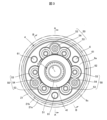
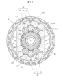
- FIG. 3 is an external view of the differential gear mechanism as viewed from one axial side.
- FIG. 4A is a cross-sectional view taken along line AA of FIG.
- FIG. 4B is a cross-sectional view taken along line BB in FIG.
- FIG. 5 is a cross-sectional view of the differential gear mechanism showing a cross section of the support.
- FIG. 6 is a cross-sectional perspective view showing the inside of the support body.
- FIG. 7 is a cross-sectional view showing a differential gear mechanism and a rotor according to the second embodiment.
- FIG. 8 is a cross-sectional view taken along line CC of FIG.
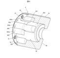
- FIG. 9 is a perspective view showing a differential gear mechanism and a rotor according to the third embodiment.
- FIG. 10 is a cross-sectional view showing a differential gear mechanism, a rotating body, and a rotor according to a third embodiment, taken along a cross section perpendicular to the axial direction.
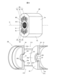
- FIG. 11 is a cross-sectional view showing a differential gear mechanism, a rotating body, and a rotor according to a third embodiment, taken along a cross section parallel to the axial direction.
- Fig. 1 is a cross-sectional view showing an example of the configuration of an electric drive device 1 according to a first embodiment of the present invention.
- This electric drive device 1 has as its main components a case 10, a pair of output shafts 11, 12, bearings 13, 14 that rotatably support the pair of output shafts 11, 12 relative to the case 10, a rotating body 2 having a cylindrical portion 21 that houses the pair of output shafts 11, 12, bearings 15, 16 that rotatably support the rotating body 2 relative to the case 10, an electric motor unit 3 arranged on the outer periphery of the cylindrical portion 21 of the rotating body 2, and a differential gear mechanism 4 that distributes the torque generated by the electric motor unit 3 to the pair of output shafts 11, 12.
- the electric drive unit 1 is mounted on a vehicle and drives the left and right wheels on the front or rear wheels.
- the case 10 is fixed to the vehicle body so as not to rotate.
- one output shaft 11 is connected to, for example, the left wheel
- the other output shaft 12 is connected to, for example, the right wheel.
- one output shaft 11 is referred to as the first output shaft 11, and the other output shaft 12 is referred to as the second output shaft 12.
- the case 10 has a first case member 101 and a second case member 102.
- the first case member 101 and the second case member 102 are fastened by a number of bolts 103.
- a bearing 13 is disposed between the first case member 101 and the first output shaft 11, and a bearing 14 is disposed between the second case member 102 and the second output shaft 12.
- the bearings 13 and 14 are, for example, needle roller bearings, but may also be plain bearings.
- the rotating body 2 rotates relative to the case 10 around a rotation axis O extending in the vehicle width direction.
- the direction parallel to the rotation axis O is referred to as the axial direction.
- the first output shaft 11 side corresponding to the left side of FIG. 1 is referred to as one axial side
- the second output shaft 12 side corresponding to the right side of FIG. 1 is referred to as the other axial side.
- the cylindrical portion 21 of the rotating body 2 has an end portion on one axial side rotatably supported by a bearing 15 relative to the first case member 101, and an end portion on the other axial side rotatably supported by a bearing 16 relative to the second case member 102.
- the bearings 15 and 16 are ball bearings and are disposed inside the cylindrical portion 21.
- the bearings 15 and 16 are not limited to ball bearings and may be, for example, tapered roller bearings.
- the bearings 15 and 16 may also be disposed outside the cylindrical portion 21.
- the electric motor section 3 has a stator 31 and a rotor 32 arranged inside the stator 31.
- the stator 31 has a stator core 311 and windings 312.
- the stator core 311 is a laminated body formed by stacking multiple electromagnetic steel plates, and is fixed to the inner circumferential surface 102a of the second case member 102 in the case 10.
- the windings 312 are wound around the stator core 311, and generate a rotating magnetic field in the stator core 311 by a current supplied from an inverter (not shown).
- the rotor 32 has a rotor core 321 and multiple magnets 322, and is fixed to the outer periphery of the cylindrical portion 21 of the rotating body 2.
- the rotor core 321 is a laminated body formed by stacking multiple electromagnetic steel sheets, and is fixed to the outer periphery 21a of the cylindrical portion 21 of the rotating body 2, for example by welding.
- the magnets 322 are held in retaining holes 321a formed in the rotor core 321.
- the rotating body 2 is a sintered body formed by sintering a compact of raw material powder, the main raw material of which is, for example, metal powder, and has a cylindrical portion 21 and a wall portion 22 provided inside the cylindrical portion 21 as an integral part.
- the cylindrical portion 21 is cylindrical and centered on the rotation axis O.
- the wall portion 22 is formed to protrude radially inward from the inner peripheral surface 21b of the cylindrical portion 21 toward the rotation axis O.
- a through hole 220 is formed in the center of the wall portion 22, and the first output shaft 11 is inserted through the through hole 220.
- FIG. 2 is a perspective view showing the rotating body 2 and the differential gear mechanism 4.
- FIG. 3 is an external view of the differential gear mechanism 4 as viewed from one axial side.
- FIG. 4A is a cross-sectional view of the differential gear mechanism 4 and the rotating body 2 taken along line A-A in FIG. 3.
- FIG. 4B is a cross-sectional view of the differential gear mechanism 4 and the rotating body 2 taken along line B-B in FIG. 3.
- FIG. 2 shows a cross-section of the rotating body 2 taken along the rotation axis O.
- FIG. 3 shows the cylindrical portion 21 of the rotating body 2 in virtual lines.
- the differential gear mechanism 4 has a plurality of gears including a pair of side gears 51, 52 connected to the first output shaft 11 and the second output shaft 12, a support 6 that supports the plurality of gears and rotates integrally with the rotating body 2, a center washer 40 arranged between the pair of side gears 51, 52, a first side washer 41 arranged on one axial side of one side gear 51, and a second side washer 42 arranged on the other axial side of the other side gear 52.
- One side gear 51 is arranged on one axial side of the center washer 40
- the other side gear 52 is arranged on the other axial side of the center washer 40.
- one side gear 51 is referred to as the first side gear 51
- the other side gear 52 is referred to as the second side gear 52.
- the rotational axes of the first side gear 51 and the second side gear 52 coincide with the rotational axis O of the rotating body 2.
- the first side gear 51 has a center hole 510 into which the first output shaft 11 is spline-fitted so that it cannot rotate relative to the first side gear 51.
- the second side gear 52 has a center hole 520 into which the second output shaft 12 is spline-fitted so that it cannot rotate relative to the second side gear 52.
- FIG. 5 is a cross-sectional view of the differential gear mechanism 4, showing the support 6 in a cross section parallel to the rotation axis O.
- FIG. 6 is a cross-sectional perspective view of the support 6, showing the inside of the support 6.
- the differential gear mechanism 4 has a plurality of gears, including a plurality of first pinion gears 53 that mesh with the first side gear 51, and a plurality of second pinion gears 54 that mesh with the second side gear 52.
- the first side gear 51 and the second side gear 52 are connected to rotate differentially by the plurality of first pinion gears 53 and the plurality of second pinion gears 54.
- the first pinion gear 53 and the second pinion gear 54 are axially shaped, and have helical helical teeth 531, 541 formed on their outer circumferences.
- the helical teeth 531 of the first pinion gear 53 mesh with the helical teeth 511 of the first side gear 51.
- the helical teeth 541 of the second pinion gear 54 mesh with the helical teeth 521 of the second side gear 52.
- the rotation axis O 53 of the first pinion gear 53 and the rotation axis O 54 of the second pinion gear 54 are parallel to the rotation axis O of the rotor 2. Note that in Figs.
- first pinion gears 53 mesh with one second pinion gear 54 to form one pinion gear set 50.
- the second pinion gear 54 is longer in the axial direction than the first pinion gear 53, meshes with the two first pinion gears 53 on one axial side of the center washer 40, and meshes with the second side gear 52 on the other axial side of the center washer 40.
- the first side gear 51 has a smaller diameter than the second side gear 52, and does not mesh with the second pinion gear 54.
- the differential gear mechanism 4 has three pinion gear sets 50. That is, in this embodiment, in addition to the first side gear 51 and the second side gear 52, the differential gear mechanism 4 has six first pinion gears 53 and three second pinion gears 54.
- the torque generated in the electric motor unit 3 is transmitted from the rotor 32 to the rotating body 2 and the support body 6, and is further distributed and transmitted from the multiple first pinion gears 53 to the first side gear 51 and from the multiple second pinion gears 54 to the second side gear 52.
- the torque transmitted to the first side gear 51 is output from the first output shaft 11 as a driving force for driving the left wheel, for example.
- the torque transmitted to the second side gear 52 is output from the second output shaft 12 as a driving force for driving the right wheel, for example.
- the support 6 is disposed in the cylindrical portion 21 with its end face 6a on one axial side facing the wall portion 22 of the rotor 2.
- a bore 60 is formed in the support 6.
- the bore 60 is a cavity that accommodates the first side gear 51, the second side gear 52, the six first pinion gears 53, and the three second pinion gears 54, and is formed in an annular shape around the rotation axis O on the outer periphery of the first output shaft 11 and the second output shaft 12.
- the first side gear 51 and the first pinion gear 53, the second side gear 52 and the second pinion gear 54, and the first pinion gear 53 and the second pinion gear 54 are each meshed in the bore 60.
- the bore 60 is formed to open to the end face 6a on one axial side of the support 6, and is closed by the wall portion 22.
- the bore 60 includes a first side gear accommodating portion 601 that accommodates the first side gear 51, a second side gear accommodating portion 602 that accommodates the second side gear 52, a plurality of first pinion gear accommodating portions 603 that respectively accommodate the plurality of first pinion gears 53, and a plurality of second pinion gear accommodating portions 604 that respectively accommodate the plurality of second pinion gears 54.
- the first side gear accommodating portion 601 communicates with the plurality of first pinion gear accommodating portions 603.
- the second side gear accommodating portion 602 communicates with the plurality of second pinion gear accommodating portions 604. Furthermore, each of the plurality of second pinion gear accommodating portions 604 communicates with two of the first pinion gear accommodating portions 603.
- the first side gear accommodating portion 601, the multiple first pinion gear accommodating portions 603, and the multiple second pinion gear accommodating portions 604 extend axially from an end face 6a on one axial side of the support body 6.
- the second side gear accommodating portion 602 is formed on the rear side of the first side gear accommodating portion 601 in the axial direction of the bore 60.
- the inner surface 603a of the first pinion gear accommodating portion 603 and the inner surface 604a of the second pinion gear accommodating portion 604 are formed to a predetermined surface roughness by, for example, machining.
- the first pinion gear accommodating portion 603, the second pinion gear accommodating portion 604, and the second side gear accommodating portion 602 are not open to the end face 6b on the other axial side of the support body 6.
- the second side washer 42, the second side gear 52, the three second pinion gears 54, the center washer 40, the first side gear 51, and the six first pinion gears 53 are sequentially inserted into the bore 60 from the end face 6a on one axial side. Movement of the first side gear 51 and the second side gear 52, as well as the multiple first pinion gears 53 and the second pinion gears 54 to the other axial side within the bore 60 is restricted by the support body 6.
- the bore 60 may also be opened on the end face 6b on the other axial side of the support 6, and some of the gears of the differential gear mechanism 4 may be inserted into the bore 60 through the opening on the other axial side end face 6b.
- the bore 60 needs to open on at least the end face 6a on one axial side, and the opening of the bore 60 on the end face 6a side needs to be blocked by the wall portion 22 of the rotating body 2.
- the wall portion 22 of the rotating body 2 restricts the axial movement of the first side gear 51 and the second side gear 52 relative to the support body 6.
- the bore 60 may also be opened toward the other axial end face 6b, allowing the second side gear 52 to be inserted into the bore 60 from the end face 6b side.
- the second side gear 52 is prevented from coming off by a movement restriction means using a retaining member such as a snap ring.
- a movement restriction means such as a snap ring.
- the first pinion gear 53 rotates about the rotation axis O53 in the first pinion gear accommodating portion 603, and the second pinion gear 54 rotates about the rotation axis O54 in the second pinion gear accommodating portion 604.
- the tooth tip surface 531a of the helical teeth 531 of the first pinion gear 53 slides on the inner surface 603a of the first pinion gear accommodating portion 603, and the tooth tip surface 541a of the helical teeth 541 of the second pinion gear 54 slides on the inner surface 604a of the second pinion gear accommodating portion 604, generating a frictional resistance force.
- This frictional resistance force prevents the first side gear 51 and the second side gear 52 from spinning freely and being unable to transmit driving force to either the left or right wheel when slippage occurs in either the left or right wheel, making it impossible to transmit driving force to either the left or right wheel.
- the frictional resistance force acting on the tooth tip surfaces 531a, 541a of the first pinion gear 53 and the second pinion gear 54 becomes a differential limiting force that limits the differential between the left and right wheels. This improves the driving stability of the vehicle.
- the support body 6 is fixed to the wall portion 22 of the rotating body 2 by a plurality of bolts 7.
- a plurality of bolt insertion holes 221 through which the bolts 7 are inserted are formed in the wall portion 22.
- a plurality of screw holes 61 into which the bolts 7 are screwed are formed in the support body 6, opening on one axial end face 6a.
- the support body 6 is fixed to the wall portion 22 by three bolts 7. Three bolt insertion holes 221 and screw holes 61 are formed in the wall portion 22 and the support body 6, respectively.
- the preassembled differential gear mechanism 4 is inserted into the cylindrical portion 21 of the rotating body 2 from the other axial end of the cylindrical portion 21, and the end face 6a on one axial side of the support 6 is abutted against the wall portion 22. Thereafter, the bolt 7 inserted into the bolt insertion hole 221 of the wall portion 22 is screwed into the screw hole 61, thereby fixing the support 6 to the wall portion 22.
- the support 6 is provided with a boss portion 62, which is a ring-shaped protrusion, at one end in the axial direction.
- the wall portion 22 is formed with a ring-shaped recess 222 into which the boss portion 62 fits.
- the outer diameter of the boss portion 62 is formed slightly smaller than the inner diameter of the recess 222, and the boss portion 62 fits into the recess 222, positioning the support 6 radially of the cylindrical portion 21 relative to the rotating body 2.
- the outer diameter D6 of the portion of the support 6 on the other axial side of the boss portion 62 is smaller than the inner diameter D21 of the cylindrical portion 21, and an annular gap is formed between the outer peripheral surface 6c of the support 6 and the inner peripheral surface 21b of the cylindrical portion 21.
- the differential gear mechanism 4 in a pre-assembled state can be inserted into the cylindrical portion 21 and fixed to the rotating body 2, so that the processing of the bore 60 in the support body 6 and the assembly of the first side gear 51, the second side gear 52, the multiple first pinion gears 53, and the multiple second pinion gears 54 to the support body 6 can be performed outside the rotating body 2.
- FIG. 7 is a cross-sectional view showing a differential gear mechanism 4A and a rotating body 2A according to a second embodiment.
- FIG. 8 is a cross-sectional view of the differential gear mechanism 4A and the rotating body 2A taken along line CC in FIG. 7.
- the rotating body 2A is provided with an engagement portion 23 integral with the cylindrical portion 21 and wall portion 22 for preventing the support body 6A of the differential gear mechanism 4A from rotating relative to the rotating body 2A.
- the engagement portion 23 is a protrusion formed by protruding radially inward from the inner peripheral surface 21b of the cylindrical portion 21.
- the rotating body 2A has three engagement portions 23 provided at equal intervals around the circumference of the cylindrical portion 21.
- Engaged portions 63 that engage with the engaging portions 23 of the rotating body 2A are formed on the support body 6A.
- the engaged portions 63 are recesses that are recessed radially inward from the outer circumferential surface 6c of the support body 6A.
- the same number of engaged portions 63 as the engaging portions 23 of the rotating body 2A are formed on the support body 6A. As shown in FIG.
- the engaged portion 63 is formed near one axial end of the support 6A, and is not formed at the other axial end of the support 6A.
- the bottom surface 63a of the engaged portion 63 is a plane parallel to the axial direction of the support 6A and perpendicular to the radial direction.
- the tip surface 23a of the engaging portion 23 is a plane that faces parallel to the bottom surface 63a of the engaged portion 63 when engaged with the engaged portion 63.
- the shapes of the engaged portion 63 and the engaging portion 23 are not limited to those described above, and may be any shape that makes it impossible for the support 6A to rotate relative to the rotating body 2A.
- the axial movement of the support 6 relative to the rotor 2 is restricted by a snap ring 8 as a restricting member.
- An annular groove 21c is formed on the inner circumferential surface 21b of the cylindrical portion 21 of the rotor 2A, and a snap ring 8 is fitted into this annular groove 21c.
- the snap ring 8 is disposed opposite the end face 6b on the other axial side of the support 6A, and restricts the movement of the support 6A to the other axial side.
- a ring-shaped bolt that screws into a female thread formed on the inner circumferential surface 21b of the cylindrical portion 21 may be used as a restricting member.
- this second embodiment also makes it possible to easily process the support 6A and assemble the differential gear mechanism 4A.
- the rotating body 2 is formed with one wall portion 22 facing the end face 6a on one axial side of the support body 6.
- the rotating body 2B of the third embodiment has walls 24, 25 on one axial side and the other axial side of the support body 6B.
- the support body 6B according to the third embodiment has a bore 60 formed to open on the end face 6a on one axial side and the end face 6b on the other axial side, and the opening of the bore 60 on the end face 6a on one axial side is closed by the wall portion 24 on one axial side, and the opening of the bore 60 on the end face 6b on the other axial side is closed by the wall portion 25 on the other axial side.
- the cylindrical portion 21 of the rotating body 2B of the third embodiment has through holes 211, 212 through which the differential gear mechanism 4B can be inserted between the two walls 24, 25. The through holes 211, 212 are closed by the rotor 32.
- the wall portion 24 on one axial side will be referred to as a first wall portion 24
- the wall portion 25 on the other axial side will be referred to as a second wall portion 25 .
- FIG. 9 is a perspective view showing the differential gear mechanism 4B and the rotating body 2B according to the third embodiment.
- FIG. 10 is a cross-sectional view showing the differential gear mechanism 4B, the rotating body 2B, and the rotor 32 according to the third embodiment in a cross section perpendicular to the axial direction.
- FIG. 11 is a cross-sectional view showing the differential gear mechanism 4B, the rotating body 2B, and the rotor 32 according to the third embodiment in a cross section parallel to the axial direction.
- the differential gear mechanism 4B has two pinion gear sets 50.
- the support body 6B has a two-face shape.
- the outer surface of the support body 6B includes a cylindrical outer peripheral surface 6c centered on the rotation axis O, and a pair of flat surfaces 6d, 6e that are parallel to each other.
- the first side gear accommodating portion 601, the second side gear accommodating portion 602, the multiple first pinion gear accommodating portions 603, and the multiple second pinion gear accommodating portions 604, which form the bore 60, are open on the end face 6a on one axial side of the support body 6B.
- the second side gear accommodating portion 602 and the multiple second pinion gear accommodating portions 604 are open on the end face 6b on the other axial side.
- the second side gear accommodating portion 602 is formed by penetrating the support body 6B in the axial direction.
- the opening of the end face 6a on one axial side of the bore 60 is closed by the first wall portion 24.
- the opening of the end face 6b on the other axial side of the bore 60 is closed by the second wall portion 25.
- the first wall portion 24 prevents the first side gear 51 from falling out of the first side gear accommodating portion 601, prevents the first pinion gears 53 from falling out of the first pinion gear accommodating portions 603, and prevents the second pinion gears 54 from falling out of the second pinion gear accommodating portions 604.
- the second wall portion 25 prevents the second side gear 52 from falling out of the second side gear accommodating portion 602, and prevents the second pinion gears 54 from falling out of the second pinion gear accommodating portions 604.
- the first wall portion 24 is formed with a through hole 240 through which the first output shaft 11 is inserted, and a first side washer accommodating portion 241 that accommodates the first side washer 41.
- the second wall portion 25 is formed with a through hole 250 through which the second output shaft 12 is inserted, and a second side washer accommodating portion 251 that accommodates the second side washer 42.
- the first side washer accommodating portion 241 is an annular recess recessed in the axial direction from the opposing surface 24a of the first wall portion 24 facing the end face 6a on one axial side of the support 6B.
- the second side washer accommodating portion 251 is an annular recess recessed in the axial direction from the opposing surface 25a of the second wall portion 25 facing the end face 6b on the other axial side of the support 6B.
- the first side washer 41 and the second side washer 42 are accommodated in the first side washer accommodating portion 241 and the second side washer accommodating portion 251, respectively.
- the support body 6B in which the first side gear 51, the second side gear 52, the plurality of first pinion gears 53, and the plurality of second pinion gears 54 are accommodated in the bore 60, is inserted into the cylindrical portion 21 from one of the through holes 211, 212 of the rotating body 2B and positioned between the first wall portion 24 and the second wall portion 25.
- the rotor 32 is fixed to the outer periphery of the cylindrical portion 21 so as to close the through holes 211, 212.
- the through holes 211, 212 are blocked by the rotor core 321, preventing the support body 6B from coming loose.
- the outer diameter of the outer peripheral surface 6c between the pair of flat surfaces 6d, 6e of the support body 6B is equal to the outer diameter of the cylindrical portion 21.
- the support body 6B is disposed so that the outer peripheral surface 6c faces the inner peripheral surface 321b of the rotor core 321.
- the cylindrical portion 21 is cut out by the through holes 211, 212 to form a pair of arc pieces 213, 214 with an arc-shaped cross section.
- the end faces 213a, 213b of one of the arc pieces 213 in the circumferential direction of the cylindrical portion 21 face one flat surface 6d of the support body 6B.
- the end faces 214a, 214b of the other of the arc pieces 214 in the circumferential direction of the cylindrical portion 21 face the other flat surface 6e of the support body 6B.
- this third embodiment also makes it possible to easily process the support body 6B and assemble the differential gear mechanism 4B.
- the rotating body 2 is formed by sintering, but this is not limiting, and the rotating body 2 may be formed by forging or casting, for example. In addition, the rotating body 2 may be formed by integrating multiple members formed by forging, casting or machining, for example by welding. The same applies to the rotating bodies 2A and 2B in the second and third embodiments.
- the first side gear 51 and the second side gear 52 are connected to rotate differentially by the shaft-shaped first pinion gear 53 and the multiple second pinion gears 54 arranged parallel to the rotation axis O, but this is not limited to the above.
- a pair of side gears made of bevel gears may be connected to rotate differentially by multiple pinion gears made of bevel gears journaled on pinion pins arranged perpendicular to the rotation axis O.
- the support supports the pair of side gears, the pinion pin, and the multiple pinion gears.
- the two first pinion gears 53 are meshed with one second pinion gear 54 to form a pinion gear set 50, but this is not limiting.
- a pinion gear set may also be formed by meshing one axial pinion gear meshing with one side gear and another axial pinion gear meshing with the other side gear.
Landscapes
- Engineering & Computer Science (AREA)
- General Engineering & Computer Science (AREA)
- Mechanical Engineering (AREA)
- Chemical & Material Sciences (AREA)
- Combustion & Propulsion (AREA)
- Transportation (AREA)
- Retarders (AREA)
Abstract
【課題】複数の歯車の組付け及び複数の歯車を支持する部材の加工が容易な電動駆動装置を提供する。 【解決手段】電動駆動装置1は、第1出力軸11及び第2出力軸12と、第1出力軸11及び第2出力軸12を収容する円筒部21を有する回転体2と、回転体2の円筒部21の外周に配置された電動モータ部3と、電動モータ部3が発生するトルクを第1出力軸11及び第2出力軸12に配分する差動歯車機構4とを備える。電動モータ部3は、ステータ31及びロータ32を有し、ロータ32が回転体2の円筒部21の外周に固定されている。差動歯車機構4は、第1サイドギヤ51及び第2サイドギヤ52を含む複数の歯車と、複数の歯車を支持する支持体6とを有する。回転体2は、円筒部21の内側に設けられた壁部22を円筒部21と一体に有し、支持体6は、軸方向一方側の端面6aが回転体2の壁部22に対向して円筒部21内に配置され、回転体2と一体に回転する。
Description
本発明は、例えば車両の車輪を駆動する、電動駆動装置に関する。
従来、車両における前輪側又は後輪側の左右の車輪を駆動する電動式の駆動装置として、特許文献1、2に記載の駆動装置が知られている。特許文献1、2に記載の駆動装置は、中空の円筒状に形成されたロータシャフトの内側に複数の歯車が収容されており、これら複数の歯車により差動歯車機構が構成されている。ロータシャフトの外側にはロータコアが固定され、ロータコアの外周にはステータコア及びステータ巻線が配置されている。ステータ巻線に電流が供給されると、ロータコア及びロータシャフトが回転し、その回転力が差動歯車機構によって一対の出力軸に差動を許容して配分される。
なお、本出願人は、エンジン等の駆動源の駆動力を左右の車輪に連結されたドライブシャフトに差動を許容して配分するための差動装置として、特許文献3に記載のものを提案している。
特許文献1、2に記載のものでは、円筒状のロータシャフトの中央部に複数の歯車を組付けなければならず、その組付け作業が困難となる。また、円筒状のロータシャフトの中央部に配置する差動歯車機構として、例えば特許文献3に記載されたもののように複数の軸状のピニオンギヤが一対の出力軸と平行に配置された構成のものを用いる場合には、複数のピニオンギヤを収容する保持孔をロータシャフトの中央部に形成する必要があり、この加工を高精度に行うことが困難となる。
本発明は、これらの事情に鑑みてなされたものであり、その目的は、複数の歯車の組付け及び複数の歯車を支持する部材の加工が容易な電動駆動装置を提供することにある。
本発明は、上記の目的を達成するため、一対の出力軸と、前記一対の出力軸を収容する円筒部を有する回転体と、前記回転体の前記円筒部の外周に配置された電動モータ部と、前記電動モータ部が発生するトルクを前記一対の出力軸に配分する差動歯車機構と、を備え、前記電動モータ部は、ステータコア及び巻線を有するステータと、前記ステータの内側に配置されたロータとを有し、前記ロータが前記回転体の前記円筒部の外周に固定されており、前記差動歯車機構は、前記一対の出力軸にそれぞれ連結された一対のサイドギヤを含む複数の歯車と、前記複数の歯車を支持する支持体とを有し、前記回転体は、前記円筒部の内側に設けられた壁部を前記円筒部と一体に有し、前記支持体は、軸方向一方側の端面が前記回転体の前記壁部に対向して前記円筒部内に配置され、前記回転体と一体に回転する、電動駆動装置を提供する。
本発明に係る電動駆動装置によれば、複数の歯車の組付け及び複数の歯車を支持する部材の加工が容易となる。
[第1の実施の形態]
本発明の第1の実施の形態について、図1乃至図6を参照して説明する。なお、以下に説明する実施の形態は、本発明を実施する上での好適な具体例として示すものであり、技術的に好ましい種々の技術的事項を具体的に例示している部分もあるが、本発明の技術的範囲は、この具体的態様に限定されるものではない。
本発明の第1の実施の形態について、図1乃至図6を参照して説明する。なお、以下に説明する実施の形態は、本発明を実施する上での好適な具体例として示すものであり、技術的に好ましい種々の技術的事項を具体的に例示している部分もあるが、本発明の技術的範囲は、この具体的態様に限定されるものではない。
図1は、本発明の第1の実施の形態に係る電動駆動装置1の構成例を示す断面図である。この電動駆動装置1は、ケース10と、一対の出力軸11,12と、ケース10に対して一対の出力軸11,12をそれぞれ回転可能に支持する軸受13,14と、一対の出力軸11,12を収容する円筒部21を有する回転体2と、ケース10に対して回転体2を回転可能に支持する軸受15,16と、回転体2の円筒部21の外周に配置された電動モータ部3と、電動モータ部3が発生するトルクを一対の出力軸11,12に配分する差動歯車機構4とを、主たる構成要素として有している。
電動駆動装置1は、車両に搭載され、前輪側又は後輪側の左右の車輪を駆動する。ケース10は、車体に対して非回転に固定される。一対の出力軸11,12のうち、一方の出力軸11は例えば左車輪に連結され、他方の出力軸12は例えば右車輪に連結される。以下、一方の出力軸11を第1出力軸11といい、他方の出力軸12を第2出力軸12という。
ケース10は、第1ケース部材101及び第2ケース部材102を有している。第1ケース部材101と第2ケース部材102とは、複数のボルト103によって締結されている。第1ケース部材101と第1出力軸11との間には軸受13が配置され、第2ケース部材102と第2出力軸12との間には軸受14が配置されている。軸受13,14は、例えば針状ころ軸受であるが、滑り軸受であってもよい。
回転体2は、車幅方向に延在する回転軸線Oを中心としてケース10に対して回転する。以下、回転軸線Oと平行な方向を軸方向という。また、図1の左方にあたる第1出力軸11側を軸方向一方側といい、図1の右方にあたる第2出力軸12側を軸方向他方側という。回転体2の円筒部21は、軸方向一方側の端部が軸受15によって第1ケース部材101に対して回転可能に支持され、軸方向他方側の端部が軸受16によって第2ケース部材102に対して回転可能に支持されている。本実施の形態では、軸受15,16が玉軸受であり、円筒部21の内側に配置されている。ただし、軸受15,16は、玉軸受に限らず、例えば円錐ころ軸受であってもよい。また、軸受15,16を円筒部21の外側に配置してもよい。
電動モータ部3は、ステータ31と、ステータ31の内側に配置されたロータ32とを有している。ステータ31は、ステータコア311及び巻線312を有している。ステータコア311は、複数の電磁鋼板を積層して構成された積層体であり、ケース10における第2ケース部材102の内周面102aに固定されている。巻線312は、ステータコア311に巻き回されており、不図示のインバータから供給される電流によってステータコア311に回転磁界を発生させる。
ロータ32は、ロータコア321及び複数の磁石322を有し、回転体2の円筒部21の外周に固定されている。ロータコア321は、複数の電磁鋼板を積層して構成された積層体であり、回転体2の円筒部21の外周面21aに例えば溶接により固定されている。磁石322は、ロータコア321に形成された保持孔321aに保持されている。ステータ31の巻線312に電流が供給されると、ロータ32が回転体2と一体に回転する。
回転体2は、例えば金属粉末を主原料とする原料粉末の圧粉体を焼結してなる焼結体であり、円筒部21と、円筒部21の内側に設けられた壁部22とを一体に有している。円筒部21は、回転軸線Oを中心とする円筒状である。壁部22は、円筒部21の内周面21bから回転軸線Oに向かって径方向内方に突出して形成されている。壁部22の中心部には、貫通孔220が形成されており、貫通孔220に第1出力軸11が挿通されている。
図2は、回転体2及び差動歯車機構4を示す斜視図である。図3は、差動歯車機構4を軸方向一方側から見た外観図である。図4Aは、図3のA-A線における差動歯車機構4及び回転体2の断面図である。図4Bは、図3のB-B線における差動歯車機構4及び回転体2の断面図である。図2では、回転軸線Oに沿った回転体2の断面を示している。図3では、回転体2の円筒部21を仮想線で示している。
差動歯車機構4は、第1出力軸11及び第2出力軸12にそれぞれ連結された一対のサイドギヤ51,52を含む複数の歯車と、これら複数の歯車を支持して回転体2と一体に回転する支持体6と、一対のサイドギヤ51,52の間に配置されたセンタワッシャ40と、一方のサイドギヤ51の軸方向一方側に配置された第1サイドワッシャ41と、他方のサイドギヤ52の軸方向他方側に配置された第2サイドワッシャ42とを有している。一方のサイドギヤ51は、センタワッシャ40の軸方向一方側に配置され、他方のサイドギヤ52は、センタワッシャ40の軸方向他方側に配置されている。以下、一方のサイドギヤ51を第1サイドギヤ51といい、他方のサイドギヤ52を第2サイドギヤ52という。第1サイドギヤ51及び第2サイドギヤ52の回転軸線は、回転体2の回転軸線Oと一致している。
第1サイドギヤ51の中心部には、第1出力軸11が相対回転不能にスプライン嵌合される嵌合穴510が形成されている。第2サイドギヤ52の中心部には、第2出力軸12が相対回転不能にスプライン嵌合される嵌合穴520が形成されている。
図5は、支持体6を回転軸線Oに平行な断面で示す差動歯車機構4の断面図である。図6は、支持体6の内側を示す支持体6の断面斜視図である。差動歯車機構4は、第1サイドギヤ51に噛み合う複数の第1ピニオンギヤ53、及び第2サイドギヤ52に噛み合う複数の第2ピニオンギヤ54を、複数の歯車として有している。第1サイドギヤ51と第2サイドギヤ52は、複数の第1ピニオンギヤ53及び複数の第2ピニオンギヤ54によって差動回転するように連結されている。
第1ピニオンギヤ53及び第2ピニオンギヤ54は、軸状であり、それぞれの外周に斜歯531,541が螺旋状に形成されている。第1ピニオンギヤ53の斜歯531は、第1サイドギヤ51の斜歯511に噛み合う。第2ピニオンギヤ54の斜歯541は、第2サイドギヤ52の斜歯521に噛み合う。第1ピニオンギヤ53の回転軸線O53及び第2ピニオンギヤ54の回転軸線O54は、回転体2の回転軸線Oと平行である。なお、図2及び図3では、第1サイドギヤ51及び第2サイドギヤ52における斜歯511,521が形成された部分、ならびに第1ピニオンギヤ53及び第2ピニオンギヤ54の斜歯531,541が形成された部分を簡略化して示している。
本実施の形態では、二つの第1ピニオンギヤ53が一つの第2ピニオンギヤ54と噛み合わされて一組のピニオンギヤ組50を構成している。第2ピニオンギヤ54は、第1ピニオンギヤ53よりも軸方向の長さが長く、センタワッシャ40よりも軸方向一方側で二つの第1ピニオンギヤ53に噛み合い、センタワッシャ40よりも軸方向他方側で第2サイドギヤ52に噛み合っている。第1サイドギヤ51は、第2サイドギヤ52よりも小径であり、第2ピニオンギヤ54とは噛み合っていない。
本実施の形態では、差動歯車機構4が三組のピニオンギヤ組50を有している。つまり、本実施の形態では、第1サイドギヤ51及び第2サイドギヤ52に加え、差動歯車機構4が六つの第1ピニオンギヤ53及び三つの第2ピニオンギヤ54を有している。電動モータ部3に発生したトルクは、ロータ32から回転体2及び支持体6に伝達され、さらに複数の第1ピニオンギヤ53から第1サイドギヤ51に、また複数の第2ピニオンギヤ54から第2サイドギヤ52に、それぞれ配分して伝達される。第1サイドギヤ51に伝達されたトルクは、例えば左車輪を駆動する駆動力として第1出力軸11から出力される。第2サイドギヤ52に伝達されたトルクは、例えば右車輪を駆動する駆動力として第2出力軸12から出力される。
支持体6は、軸方向一方側の端面6aが回転体2の壁部22に対向して円筒部21内に配置されている。支持体6には、ボア60が形成されている。ボア60は、第1サイドギヤ51、第2サイドギヤ52、六つの第1ピニオンギヤ53、及び三つの第2ピニオンギヤ54を収容する空洞であり、第1出力軸11及び第2出力軸12の外周に、回転軸線Oを中心として環状に形成されている。第1サイドギヤ51と第1ピニオンギヤ53、第2サイドギヤ52と第2ピニオンギヤ54、及び第1ピニオンギヤ53と第2ピニオンギヤ54は、それぞれボア60内で噛み合わされている。ボア60は、支持体6の軸方向一方側の端面6aに開口して形成されており、壁部22によって閉塞されている。
ボア60は、図6に示すように、第1サイドギヤ51を収容する第1サイドギヤ収容部601と、第2サイドギヤ52を収容する第2サイドギヤ収容部602と、複数の第1ピニオンギヤ53をそれぞれ収容する複数の第1ピニオンギヤ収容部603と、複数の第2ピニオンギヤ54をそれぞれ収容する複数の第2ピニオンギヤ収容部604とを含んでいる。第1サイドギヤ収容部601は、複数の第1ピニオンギヤ収容部603と連通している。第2サイドギヤ収容部602は、複数の第2ピニオンギヤ収容部604と連通している。また、複数の第2ピニオンギヤ収容部604のそれぞれは、二つの第1ピニオンギヤ収容部603と連通している。
第1サイドギヤ収容部601、複数の第1ピニオンギヤ収容部603、複数の第2ピニオンギヤ収容部604は、支持体6の軸方向一方側の端面6aから軸方向に延在している。第2サイドギヤ収容部602は、ボア60の軸方向における第1サイドギヤ収容部601の奥側に形成されている。第1ピニオンギヤ収容部603の内面603a及び第2ピニオンギヤ収容部604の内面604aは、例えば機械加工により所定の面粗度に形成されている。
本実施の形態では、支持体6における軸方向他方側の端面6bに第1ピニオンギヤ収容部603、第2ピニオンギヤ収容部604、及び第2サイドギヤ収容部602が開放されていない。差動歯車機構4を組み立てる際には、軸方向一方側の端面6aからボア60内に、第2サイドワッシャ42、第2サイドギヤ52、三つの第2ピニオンギヤ54、センタワッシャ40、第1サイドギヤ51、及び六つの第1ピニオンギヤ53を順次挿入する。第1サイドギヤ51及び第2サイドギヤ52、ならびに複数の第1ピニオンギヤ53及び第2ピニオンギヤ54のボア60内における軸方向他方側への移動は、支持体6によって規制されている。
ただし、支持体6の軸方向他方側の端面6bにもボア60を開口させ、この軸方向他方側の端面6b側の開口からボア60内に差動歯車機構4が有する複数の歯車のうちの一部を挿入可能としてもよい。つまり、ボア60は、少なくとも軸方向一方側の端面6aに開口し、この端面6a側におけるボア60の開口が回転体2の壁部22によって閉塞されていればよい。
本実施の形態では、上記の構成により、回転体2の壁部22が第1サイドギヤ51及び第2サイドギヤ52の支持体6に対する軸方向移動を規制している。ただし、ボア60を軸方向他方側の端面6b側にも開口させ、端面6b側からボア60内に第2サイドギヤ52を挿入可能としてもよい。この場合には、例えばスナップリング等の抜け止め部材を用いた移動規制手段により、第2サイドギヤ52を抜け止めする。つまり、回転体2の壁部22は、第1サイドギヤ51及び第2サイドギヤ52のうち少なくとも何れかの支持体6に対する軸方向移動を規制していればよい。
車両の走行時に左車輪と右車輪の間に車輪速差が生じ、第1サイドギヤ51と第2サイドギヤ52とが差動回転する際には、第1ピニオンギヤ53が第1ピニオンギヤ収容部603内で回転軸線O53を中心として自転し、第2ピニオンギヤ54が第2ピニオンギヤ収容部604内で回転軸線O54を中心として自転する。この際、第1ピニオンギヤ53の斜歯531の歯先面531aが第1ピニオンギヤ収容部603の内面603aを摺動すると共に第2ピニオンギヤ54の斜歯541の歯先面541aが第2ピニオンギヤ収容部604の内面604aを摺動し、摩擦抵抗力が発生する。
この摩擦抵抗力により、左車輪及び右車輪の何れかにスリップが発生して駆動力を伝達できなくなった場合に第1サイドギヤ51及び第2サイドギヤ52が空転し、左車輪及び右車輪の何れにも駆動力を伝達できなくなることが抑制される。つまり、第1ピニオンギヤ53及び第2ピニオンギヤ54の歯先面531a,541aに作用する摩擦抵抗力が左車輪及び右車輪の差動を制限する差動制限力となる。これにより、車両の走行安定性が向上する。
支持体6は、複数のボルト7によって回転体2の壁部22に固定される。壁部22には、ボルト7が挿通される複数のボルト挿通孔221が形成されている。支持体6には、ボルト7が螺合する複数のねじ穴61が軸方向一方側の端面6aに開口して形成されている。本実施の形態では、三本のボルト7によって支持体6が壁部22に固定される。壁部22及び支持体6には、それぞれ三つのボルト挿通孔221及びねじ穴61が形成されている。
差動歯車機構4を回転体2に組付ける際には、回転体2における円筒部21の軸方向他方側の端部から、予め組み立てられた差動歯車機構4を円筒部21内に挿入し、支持体6の軸方向一方側の端面6aを壁部22に突き当てる。その後、壁部22のボルト挿通孔221に挿通されたボルト7をねじ穴61に螺合することにより、支持体6が壁部22に固定される。
支持体6には、軸方向一方側の端部に環状の突起であるボス部62が設けられている。壁部22には、ボス部62が嵌合する環状の凹部222が形成されている。ボス部62の外径は凹部222の内径よりも僅かに小さく形成されており、ボス部62が凹部222に嵌合することで、支持体6が回転体2に対して円筒部21の径方向に位置決めされる。
図1に示すように、支持体6におけるボス部62よりも軸方向他方側にあたる部分の外径D6は、円筒部21の内径D21よりも小さく、支持体6の外周面6cと円筒部21の内周面21bとの間に環状の隙間が形成される。この構成により、支持体6のボス部62が壁部22の凹部222に嵌合するまで、支持体6を円滑に円筒部21内に挿入することができる。
以上説明した第1の実施の形態によれば、予め組み立てた状態の差動歯車機構4を円筒部21内に挿入して回転体2に固定することができるので、支持体6に対するボア60の加工や、支持体6への第1サイドギヤ51、第2サイドギヤ52、複数の第1ピニオンギヤ53、及び複数の第2ピニオンギヤ54の組付けを、回転体2の外部で行うことができる。これにより、支持体6に対する加工や差動歯車機構4の組み立てを容易に行うことが可能となる。
[第2の実施の形態]
次に、本発明の第2の実施の形態について図7及び図8を参照して説明する。第1の実施の形態では、支持体6を複数のボルト7によって回転体2の壁部22に固定する場合について説明した。第2の実施の形態では、回転体2Aの円筒部21への嵌合により支持体6Aの回転体2Aに対する相対回転が規制されると共に、円筒部21に取り付けられた規制部材によって支持体6Aの回転体2Aに対する軸方向の移動が規制される。
次に、本発明の第2の実施の形態について図7及び図8を参照して説明する。第1の実施の形態では、支持体6を複数のボルト7によって回転体2の壁部22に固定する場合について説明した。第2の実施の形態では、回転体2Aの円筒部21への嵌合により支持体6Aの回転体2Aに対する相対回転が規制されると共に、円筒部21に取り付けられた規制部材によって支持体6Aの回転体2Aに対する軸方向の移動が規制される。
以下、第2の実施の形態について具体的に説明する。図7及び図8に示す電動駆動装置の構成要素のうち第1の実施の形態で説明したものと共通するものについては、図1乃至図6に付したものと同一の符号を付して重複した説明を省略する。
図7は、第2の実施の形態に係る差動歯車機構4A及び回転体2Aを示す断面図である。図8は、図7のC-C線における差動歯車機構4A及び回転体2Aの断面図である。回転体2Aには、円筒部21及び壁部22に加え、回転体2Aに対して差動歯車機構4Aの支持体6Aを回り止めするための係合部23が、円筒部21及び壁部22と一体に設けられている。本実施の形態では、係合部23が円筒部21の内周面21bから径方向内方に向かって突出して形成された突起である。回転体2Aには、三つの係合部23が円筒部21の周方向等間隔に設けられている。
支持体6Aには、回転体2Aの係合部23に係合する被係合部63が形成されている。被係合部63は、支持体6Aの外周面6cから径方向内方に向かって窪む凹部である。支持体6Aには、回転体2Aの係合部23と同数の被係合部63が形成されている。図8に示すように、支持体6Aの軸方向一方側の端面6aが壁部22に当接するまで差動歯車機構4Aが円筒部21内に挿入され、支持体6Aが円筒部21に嵌合すると、回転体2Aの複数の係合部23が支持体6Aの複数の被係合部63にそれぞれ係合し、支持体6Aが回転体2Aに対して回り止めされる。これにより、支持体6Aが回転体2Aと一体に回転する。
被係合部63は、支持体6Aにおける軸方向一方側の端部付近に形成されており、支持体6Aにおける軸方向他方の端部には形成されていない。本実施の形態では、被係合部63の底面63aが支持体6Aの軸方向に平行で径方向に対して垂直な平面である。係合部23の先端面23aは、被係合部63に係合したときに被係合部63の底面63aと平行に向かい合う平面である。ただし、被係合部63及び係合部23の形状は、上記のものに限らず、支持体6Aを回転体2Aに対して相対回転不能とすることができる形状であればよい。
図8に示す例では、規制部材としてのスナップリング8によって支持体6の回転体2に対する軸方向の移動が規制されている。回転体2Aの円筒部21の内周面21bには、環状溝21cが形成されており、この環状溝21cにスナップリング8が嵌着されている。スナップリング8は、支持体6Aの軸方向他方側の端面6bに対向して配置され、支持体6Aの軸方向他方側への移動を規制している。なお、スナップリング8に替えて、円筒部21の内周面21bに形成された雌ねじに螺合するリング状のボルトを規制部材として用いてもよい。
この第2の実施の形態によっても、第1の実施の形態と同様に、支持体6Aに対する加工や差動歯車機構4Aの組み立てを容易に行うことが可能となる。
[第3の実施の形態]
次に、本発明の第3の実施の形態について図9乃至図11を参照して説明する。第1の実施の形態では、回転体2に支持体6の軸方向一方側の端面6aに対向する一つの壁部22が形成された場合について説明した。第3の実施の形態の回転体2Bは、支持体6Bの軸方向一方側及び軸方向他方側にそれぞれ壁部24,25を有している。また、第3の実施の形態に係る支持体6Bは、ボア60が軸方向一方側の端面6a及び軸方向他方側の端面6bに開口して形成されており、軸方向一方側の端面6aにおけるボア60の開口が軸方向一方側の壁部24によって閉塞され、軸方向他方側の端面6bにおけるボア60の開口が軸方向他方側の壁部25によって閉塞されている。またさらに、第3の実施の形態の回転体2Bの円筒部21には、差動歯車機構4Bを二つの壁部24,25の間に挿入することが可能な貫通孔211,212が形成されている。貫通孔211,212は、ロータ32によって閉塞される。以下、二つの壁部24,25のうち、軸方向一方側の壁部24を第1壁部24といい、軸方向他方側の壁部25を第2壁部25という。
次に、本発明の第3の実施の形態について図9乃至図11を参照して説明する。第1の実施の形態では、回転体2に支持体6の軸方向一方側の端面6aに対向する一つの壁部22が形成された場合について説明した。第3の実施の形態の回転体2Bは、支持体6Bの軸方向一方側及び軸方向他方側にそれぞれ壁部24,25を有している。また、第3の実施の形態に係る支持体6Bは、ボア60が軸方向一方側の端面6a及び軸方向他方側の端面6bに開口して形成されており、軸方向一方側の端面6aにおけるボア60の開口が軸方向一方側の壁部24によって閉塞され、軸方向他方側の端面6bにおけるボア60の開口が軸方向他方側の壁部25によって閉塞されている。またさらに、第3の実施の形態の回転体2Bの円筒部21には、差動歯車機構4Bを二つの壁部24,25の間に挿入することが可能な貫通孔211,212が形成されている。貫通孔211,212は、ロータ32によって閉塞される。以下、二つの壁部24,25のうち、軸方向一方側の壁部24を第1壁部24といい、軸方向他方側の壁部25を第2壁部25という。
図9は、第3の実施の形態に係る差動歯車機構4B及び回転体2Bを示す斜視図である。図10は、第3の実施の形態に係る差動歯車機構4B及び回転体2Bならびにロータ32を軸方向に対して垂直な断面で示す断面図である。図11は、第3の実施の形態に係る差動歯車機構4B及び回転体2Bならびにロータ32を軸方向に対して平行な断面で示す断面図である。
本実施の形態では、差動歯車機構4Bが二組のピニオンギヤ組50を有している。また、本実施の形態では、支持体6Bが二面幅形状を有している。つまり、支持体6Bの外面が、回転軸線Oを中心とする円筒状の外周面6cと、互いに平行な一対の平坦面6d,6eとを含んでいる。
支持体6Bの軸方向一方側の端面6aには、ボア60を形成する第1サイドギヤ収容部601、第2サイドギヤ収容部602、複数の第1ピニオンギヤ収容部603、複数の第2ピニオンギヤ収容部604のうち、第1サイドギヤ収容部601、複数の第1ピニオンギヤ収容部603、及び複数の第2ピニオンギヤ収容部604が開口している。軸方向他方側の端面6bには、第2サイドギヤ収容部602、及び複数の第2ピニオンギヤ収容部604が開口している。第2サイドギヤ収容部602は、支持体6Bを軸方向に貫通して形成されている。
ボア60における軸方向一方側の端面6aの開口は、第1壁部24によって閉塞されている。ボア60における軸方向他方側の端面6bの開口は、第2壁部25によって閉塞されている。第1壁部24は、第1サイドギヤ51を第1サイドギヤ収容部601から抜け止めし、複数の第1ピニオンギヤ53を複数の第1ピニオンギヤ収容部603から抜け止めし、かつ複数の第2ピニオンギヤ54を複数の第2ピニオンギヤ収容部604から抜け止めしている。第2壁部25は、第2サイドギヤ52を第2サイドギヤ収容部602から抜け止めし、かつ複数の第2ピニオンギヤ54を複数の第2ピニオンギヤ収容部604から抜け止めしている。
第1壁部24には、第1出力軸11が挿通される貫通孔240、及び第1サイドワッシャ41を収容する第1サイドワッシャ収容部241が形成されている。第2壁部25には、第2出力軸12が挿通される貫通孔250、及び第2サイドワッシャ42を収容する第2サイドワッシャ収容部251が形成されている。第1サイドワッシャ収容部241は、第1壁部24における支持体6Bの軸方向一方側の端面6aとの対向面24aから軸方向に窪んだ環状の凹部である。第2サイドワッシャ収容部251は、第2壁部25における支持体6Bの軸方向他方側の端面6bとの対向面25aから軸方向に窪んだ環状の凹部である。
差動歯車機構4Bを回転体2Bに組付ける際には、第1サイドワッシャ41及び第2サイドワッシャ42を第1サイドワッシャ収容部241及び第2サイドワッシャ収容部251にそれぞれ収容する。その後、ボア60に第1サイドギヤ51、第2サイドギヤ52、複数の第1ピニオンギヤ53、及び複数の第2ピニオンギヤ54が収容された支持体6Bを回転体2Bの貫通孔211,212の何れかから円筒部21に挿入し、第1壁部24と第2壁部25との間に配置する。その後さらに、貫通孔211,212を塞ぐようにロータ32を円筒部21の外周に固定する。貫通孔211,212は、ロータコア321によって閉塞され、支持体6Bが抜け止めされる。支持体6Bの一対の平坦面6d,6eの間の外周面6cは、その外径が円筒部21の外径と同等である。支持体6Bは、外周面6cがロータコア321の内周面321bに対向して配置される。
回転体2Bの軸方向における第1壁部24と第2壁部25との間の位置では、円筒部21が貫通孔211,212によって切り欠かれることにより、断面円弧状の一対の円弧片213,214が形成されている。円筒部21の周方向における一方の円弧片213の端面213a,213bは、支持体6Bの一方の平坦面6dに対向する。また、円筒部21の周方向における他方の円弧片214の端面214a,214bは、支持体6Bの他方の平坦面6eに対向する。このように支持体6Bが一対の円弧片213,214の間に配置されることにより、支持体6Bが回転体2Bと一体に回転する。
この第3の実施の形態によっても、第1の実施の形態と同様に、支持体6Bに対する加工や差動歯車機構4Bの組み立てを容易に行うことが可能となる。
(付記)
以上、本発明を第1乃至第3の実施の形態に基づいて説明したが、これらの実施の形態は請求の範囲に係る発明を限定するものではない。また、実施の形態の中で説明した特徴の組合せの全てが発明の課題を解決するための手段に必須であるとは限らない点に留意すべきである。また、本発明は、その趣旨を逸脱しない範囲で、一部の構成を省略し、あるいは構成を追加もしくは置換して、適宜変形して実施することが可能である。またさらに、上記した複数の実施の形態の一部の構成を互いに組み合わせることも可能であると共に、例えば下記のように変形することも可能である。
以上、本発明を第1乃至第3の実施の形態に基づいて説明したが、これらの実施の形態は請求の範囲に係る発明を限定するものではない。また、実施の形態の中で説明した特徴の組合せの全てが発明の課題を解決するための手段に必須であるとは限らない点に留意すべきである。また、本発明は、その趣旨を逸脱しない範囲で、一部の構成を省略し、あるいは構成を追加もしくは置換して、適宜変形して実施することが可能である。またさらに、上記した複数の実施の形態の一部の構成を互いに組み合わせることも可能であると共に、例えば下記のように変形することも可能である。
第1の実施の形態では、回転体2を焼結によって形成した場合について説明したが、これに限らず、例えば鍛造や鋳造によって回転体2を形成してもよい。また、鍛造や鋳造もしくは機械加工によって形成した複数の部材を例えば溶接により一体として回転体2を形成してもよい。第2の実施の形態及び第3の実施の形態の回転体2A,2Bについても同様である。
第1乃至第3の実施の形態では、第1サイドギヤ51と第2サイドギヤ52が、回転軸線Oと平行に配置された軸状の第1ピニオンギヤ53及び複数の第2ピニオンギヤ54によって差動回転するように連結された場合について説明したが、これに限らない。例えば、傘歯車からなる一対のサイドギヤが、回転軸線Oに対して垂直に設けられたピニオンピンに軸支された傘歯車からなる複数のピニオンギヤによって差動回転するように連結されていてもよい。この場合、支持体は、一対のサイドギヤ、ピニオンピン、及び複数のピニオンギヤを支持する。
第1乃至第3の実施の形態では、二つの第1ピニオンギヤ53が一つの第2ピニオンギヤ54と噛み合わされて一組のピニオンギヤ組50を構成する場合について説明したが、これに限らず、一方のサイドギヤに噛み合う一つの軸状のピニオンギヤと他方のサイドギヤに噛み合う一つの軸状のピニオンギヤとを互いに噛み合わせて一組のピニオンギヤ組を構成してもよい。
1…電動駆動装置
11…第1出力軸
12…第2出力軸
2,2A,2B…回転体
21…円筒部
21d,21e…貫通孔
22…壁部
24…第1壁部
25…第2壁部
3…電動モータ部
31…ステータ
311…ステータコア
312…巻線
32…ロータ
4,4A,4B…差動歯車機構
51…第1サイドギヤ
52…第2サイドギヤ
53…第1ピニオンギヤ
54…第2ピニオンギヤ
6,6A,6B…支持体
60…ボア
O,O53,O54…回転軸線
11…第1出力軸
12…第2出力軸
2,2A,2B…回転体
21…円筒部
21d,21e…貫通孔
22…壁部
24…第1壁部
25…第2壁部
3…電動モータ部
31…ステータ
311…ステータコア
312…巻線
32…ロータ
4,4A,4B…差動歯車機構
51…第1サイドギヤ
52…第2サイドギヤ
53…第1ピニオンギヤ
54…第2ピニオンギヤ
6,6A,6B…支持体
60…ボア
O,O53,O54…回転軸線
Claims (8)
- 一対の出力軸と、前記一対の出力軸を収容する円筒部を有する回転体と、前記回転体の前記円筒部の外周に配置された電動モータ部と、前記電動モータ部が発生するトルクを前記一対の出力軸に配分する差動歯車機構と、を備え、
前記電動モータ部は、ステータコア及び巻線を有するステータと、前記ステータの内側に配置されたロータとを有し、前記ロータが前記回転体の前記円筒部の外周に固定されており、
前記差動歯車機構は、前記一対の出力軸にそれぞれ連結された一対のサイドギヤを含む複数の歯車と、前記複数の歯車を支持する支持体とを有し、
前記回転体は、前記円筒部の内側に設けられた壁部を前記円筒部と一体に有し、
前記支持体は、軸方向一方側の端面が前記回転体の前記壁部に対向して前記円筒部内に配置され、前記回転体と一体に回転する、
電動駆動装置。 - 前記支持体には、前記複数の歯車を収容するボアが少なくとも前記軸方向一方側の端面に開口して形成されており、
前記ボアにおける前記軸方向一方側の開口が前記回転体の前記壁部により閉塞されている、
請求項1に記載の電動駆動装置。 - 前記回転体の前記壁部は、前記一対のサイドギヤのうち少なくとも何れか一方のサイドギヤの前記支持体に対する軸方向移動を規制している、
請求項1又は2に記載の電動駆動装置。 - 前記差動歯車機構は、前記一対のサイドギヤのうち一方のサイドギヤに噛み合う第1ピニオンギヤ、及び前記一対のサイドギヤのうち他方のサイドギヤに噛み合う第2ピニオンギヤを、前記複数の歯車として有し、
前記一対のサイドギヤの回転軸線が前記回転体の回転軸線と一致しており、
前記第1ピニオンギヤの回転軸線、及び前記第2ピニオンギヤの回転軸線が、前記一対のサイドギヤの回転軸線と平行であり、
前記第1ピニオンギヤと前記第2ピニオンギヤとが前記ボア内で噛み合わされている、
請求項2に記載の電動駆動装置。 - 前記一対のサイドギヤ、前記第1ピニオンギヤ、及び前記第2ピニオンギヤの前記ボア内における軸方向他方側への移動が前記支持体によって規制されている、
請求項4に記載の電動駆動装置。 - 前記支持体は、前記円筒部への嵌合により前記回転体に対する相対回転が規制され、前記円筒部に取り付けられた規制部材によって前記回転体に対する軸方向の移動が規制されている、
請求項5に記載の電動駆動装置。 - 前記ボアが前記支持体の前記軸方向一方側の端面及び軸方向他方側の端面に開口して形成されており、
前記回転体は、前記壁部を前記支持体の前記軸方向一方側及び前記軸方向他方側にそれぞれ有し、
前記ボアの前記軸方向他方側の開口が、前記支持体の前記軸方向他方側に設けられた前記壁部により閉塞されている、
請求項4に記載の電動駆動装置。 - 前記回転体の前記円筒部に、前記支持体を前記軸方向一方側の前記壁部及び前記軸方向他方側の前記壁部の間に挿入可能な貫通孔が形成されており、
前記貫通孔が前記ロータによって閉塞されている、
請求項7に記載の電動駆動装置。
Priority Applications (1)
| Application Number | Priority Date | Filing Date | Title |
|---|---|---|---|
| PCT/JP2023/025112 WO2025009151A1 (ja) | 2023-07-06 | 2023-07-06 | 電動駆動装置 |
Applications Claiming Priority (1)
| Application Number | Priority Date | Filing Date | Title |
|---|---|---|---|
| PCT/JP2023/025112 WO2025009151A1 (ja) | 2023-07-06 | 2023-07-06 | 電動駆動装置 |
Publications (1)
| Publication Number | Publication Date |
|---|---|
| WO2025009151A1 true WO2025009151A1 (ja) | 2025-01-09 |
Family
ID=94171665
Family Applications (1)
| Application Number | Title | Priority Date | Filing Date |
|---|---|---|---|
| PCT/JP2023/025112 Ceased WO2025009151A1 (ja) | 2023-07-06 | 2023-07-06 | 電動駆動装置 |
Country Status (1)
| Country | Link |
|---|---|
| WO (1) | WO2025009151A1 (ja) |
Citations (4)
| Publication number | Priority date | Publication date | Assignee | Title |
|---|---|---|---|---|
| JPH06323373A (ja) * | 1993-03-24 | 1994-11-25 | Zexel Gleason Usa Inc | 差動歯車装置 |
| JPH0974713A (ja) * | 1995-09-04 | 1997-03-18 | Toyota Motor Corp | 電動モータ |
| DE19954590A1 (de) * | 1999-11-12 | 2001-05-17 | Linde Ag | Antriebsanordnung mit einem Elektromotor |
| JP2019007505A (ja) * | 2017-06-21 | 2019-01-17 | 株式会社ジェイテクト | 差動装置 |
-
2023
- 2023-07-06 WO PCT/JP2023/025112 patent/WO2025009151A1/ja not_active Ceased
Patent Citations (4)
| Publication number | Priority date | Publication date | Assignee | Title |
|---|---|---|---|---|
| JPH06323373A (ja) * | 1993-03-24 | 1994-11-25 | Zexel Gleason Usa Inc | 差動歯車装置 |
| JPH0974713A (ja) * | 1995-09-04 | 1997-03-18 | Toyota Motor Corp | 電動モータ |
| DE19954590A1 (de) * | 1999-11-12 | 2001-05-17 | Linde Ag | Antriebsanordnung mit einem Elektromotor |
| JP2019007505A (ja) * | 2017-06-21 | 2019-01-17 | 株式会社ジェイテクト | 差動装置 |
Similar Documents
| Publication | Publication Date | Title |
|---|---|---|
| JP5910378B2 (ja) | 減速機構及びこれを備えたモータ回転力伝達装置 | |
| JP6767804B2 (ja) | 歯車変速機 | |
| KR102633278B1 (ko) | 기어모터 | |
| WO2018008692A1 (ja) | 波動歯車減速機用モータユニット | |
| EP4141287B1 (en) | Transmission mechanism | |
| EP3922880A1 (en) | Power transmission device | |
| JP2017036825A (ja) | 遊星歯車減速機および駆動機構 | |
| JP2025096420A (ja) | 車両用駆動装置 | |
| WO2022064725A1 (ja) | 減速装置及び電気機器 | |
| WO2025009151A1 (ja) | 電動駆動装置 | |
| JP7487438B2 (ja) | 動力伝達装置 | |
| JP7164791B2 (ja) | 波動歯車減速機用モータユニット | |
| CN114542684B (zh) | 差动装置 | |
| JP4219618B2 (ja) | 小型ウォーム併用ギヤードモータ | |
| JP2014050217A (ja) | 回転電機 | |
| JP5659588B2 (ja) | ホイール軸受および電動車両駆動装置 | |
| JP4672983B2 (ja) | 減速機の出力部構造 | |
| JP2016098989A (ja) | モータ一体型減速機の組み付け方法及びモータ一体型減速機 | |
| JP2024090827A (ja) | 車両用駆動装置 | |
| JP2013221570A (ja) | 変速歯車装置およびアクチュエータ | |
| WO2025004294A1 (ja) | 差動減速装置及び電動駆動装置 | |
| WO2020183815A1 (ja) | 動力伝達装置 | |
| JP2025002488A (ja) | 車両用駆動伝達装置 | |
| WO2025141947A1 (ja) | 車両用駆動装置 | |
| JP2012052589A (ja) | 軸受構造 |
Legal Events
| Date | Code | Title | Description |
|---|---|---|---|
| 121 | Ep: the epo has been informed by wipo that ep was designated in this application |
Ref document number: 23942633 Country of ref document: EP Kind code of ref document: A1 |
|
| NENP | Non-entry into the national phase |
Ref country code: DE |