WO2025009130A1 - 工作機械制御装置 - Google Patents
工作機械制御装置 Download PDFInfo
- Publication number
- WO2025009130A1 WO2025009130A1 PCT/JP2023/025028 JP2023025028W WO2025009130A1 WO 2025009130 A1 WO2025009130 A1 WO 2025009130A1 JP 2023025028 W JP2023025028 W JP 2023025028W WO 2025009130 A1 WO2025009130 A1 WO 2025009130A1
- Authority
- WO
- WIPO (PCT)
- Prior art keywords
- spindle
- compressed air
- machine tool
- supply
- control device
- Prior art date
- Legal status (The legal status is an assumption and is not a legal conclusion. Google has not performed a legal analysis and makes no representation as to the accuracy of the status listed.)
- Ceased
Links
Images




Classifications
-
- F—MECHANICAL ENGINEERING; LIGHTING; HEATING; WEAPONS; BLASTING
- F16—ENGINEERING ELEMENTS AND UNITS; GENERAL MEASURES FOR PRODUCING AND MAINTAINING EFFECTIVE FUNCTIONING OF MACHINES OR INSTALLATIONS; THERMAL INSULATION IN GENERAL
- F16J—PISTONS; CYLINDERS; SEALINGS
- F16J15/00—Sealings
- F16J15/44—Free-space packings
- F16J15/447—Labyrinth packings
-
- F—MECHANICAL ENGINEERING; LIGHTING; HEATING; WEAPONS; BLASTING
- F16—ENGINEERING ELEMENTS AND UNITS; GENERAL MEASURES FOR PRODUCING AND MAINTAINING EFFECTIVE FUNCTIONING OF MACHINES OR INSTALLATIONS; THERMAL INSULATION IN GENERAL
- F16J—PISTONS; CYLINDERS; SEALINGS
- F16J15/00—Sealings
- F16J15/16—Sealings between relatively-moving surfaces
- F16J15/40—Sealings between relatively-moving surfaces by means of fluid
-
- G—PHYSICS
- G05—CONTROLLING; REGULATING
- G05B—CONTROL OR REGULATING SYSTEMS IN GENERAL; FUNCTIONAL ELEMENTS OF SUCH SYSTEMS; MONITORING OR TESTING ARRANGEMENTS FOR SUCH SYSTEMS OR ELEMENTS
- G05B19/00—Program-control systems
- G05B19/02—Program-control systems electric
- G05B19/18—Numerical control [NC], i.e. automatically operating machines, in particular machine tools, e.g. in a manufacturing environment, so as to execute positioning, movement or co-ordinated operations by means of program data in numerical form
-
- B—PERFORMING OPERATIONS; TRANSPORTING
- B23—MACHINE TOOLS; METAL-WORKING NOT OTHERWISE PROVIDED FOR
- B23Q—DETAILS, COMPONENTS, OR ACCESSORIES FOR MACHINE TOOLS, e.g. ARRANGEMENTS FOR COPYING OR CONTROLLING; MACHINE TOOLS IN GENERAL CHARACTERISED BY THE CONSTRUCTION OF PARTICULAR DETAILS OR COMPONENTS; COMBINATIONS OR ASSOCIATIONS OF METAL-WORKING MACHINES, NOT DIRECTED TO A PARTICULAR RESULT
- B23Q11/00—Accessories fitted to machine tools for keeping tools or parts of the machine in good working condition or for cooling work; Safety devices specially combined with or arranged in, or specially adapted for use in connection with, machine tools
- B23Q11/08—Protective coverings for parts of machine tools; Splash guards
- B23Q11/0883—Protective coverings for parts of machine tools; Splash guards for spindles, e.g. for their bearings or casings
-
- G—PHYSICS
- G05—CONTROLLING; REGULATING
- G05B—CONTROL OR REGULATING SYSTEMS IN GENERAL; FUNCTIONAL ELEMENTS OF SUCH SYSTEMS; MONITORING OR TESTING ARRANGEMENTS FOR SUCH SYSTEMS OR ELEMENTS
- G05B2219/00—Program-control systems
- G05B2219/30—Nc systems
- G05B2219/49—Nc machine tool, till multiple
- G05B2219/49052—Accessory, coolant
Definitions
- This disclosure relates to a machine tool control device.
- compressed air with preset, fixed supply conditions is used as the air (compressed air) introduced (supplied) to maintain positive pressure inside the spindle.
- the required supply conditions differ depending on the operating conditions, there is a risk of consuming more compressed air than necessary.
- the aim is to provide a machine tool control device that can reduce the amount of compressed air consumed.
- One aspect of the present disclosure is a machine tool control device that controls a machine tool having a spindle and a compressed air supply device that supplies compressed air to the inside of the spindle, the machine tool control device including: a rotational state information acquisition unit that acquires rotational state information indicating the rotational state of the spindle; a supply condition determination unit that determines the supply conditions required for the compressed air to be supplied to the inside of the spindle based on the rotational state information acquired by the rotational state information acquisition unit; and a compressed air control unit that controls the compressed air supply device based on the supply conditions determined by the supply condition determination unit.
- FIG. 2 is a schematic diagram showing an example of the vicinity of a spindle of the machine tool according to the present embodiment.
- 1 is a block diagram showing a hardware configuration of a machine tool control device according to an embodiment of the present invention
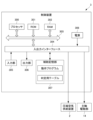
- FIG. 2 is a block diagram for explaining the functional configuration of the machine tool control device according to the present embodiment.
- 4 is a flowchart for explaining an example of compressed air supply control by the machine tool control device according to the present embodiment.
- FIG. 13 is a block diagram showing a hardware configuration of a machine tool control device according to a modified example.
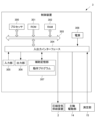
- FIG. 13 is a block diagram for explaining a functional configuration of a machine tool control device according to a modified example.
- FIG. 1 is a schematic diagram showing an example of the vicinity of a spindle 1 of the machine tool M according to this embodiment.
- Figure 2 is a block diagram showing the hardware configuration of a machine tool control device 3 according to this embodiment.
- Figure 3 is a block diagram for explaining the functional configuration of the machine tool control device 3 according to this embodiment.
- the machine tool M is a device having a spindle to which a tool is attached and which is rotated to perform machining.
- the machine tool M has a spindle 1, a compressed air supply device 2, and a machine tool control device 3.
- the spindle 1 is a device that rotates and transmits power for machining in the machine tool M.
- the spindle 1 can be used in various machine tools. Details will be described later.
- the compressed air supply device 2 is configured to supply compressed air to the inside of the spindle 1.
- the compressed air supply device 2 according to this embodiment supplies compressed air to the inside of the spindle 1 via a labyrinth seal 13, which is a non-contact seal structure described below.
- the compressed air supply device 2 is, for example, a pump. Note that the compressed air supply device 2 is not limited to a pump. For example, it may be a common compressor for the equipment of the entire factory.
- the machine tool control device 3 is configured to control various operations of the machine tool M. Details will be described later.
- the spindle 1 has a spindle shaft 10, a plurality of bearings 11, a housing 12, and a labyrinth seal 13 as a contactless seal structure, and as shown in Figures 2 and 3, a spindle drive unit 14.
- the spindle shaft 10 is a cylindrical member for transmitting the power of the drive section to the machining section of the machine tool M. As shown in FIG. 1, the spindle shaft 10 has a stopper 10a fixed to its outer circumferential surface.
- the stopper 10a is configured to restrict the movement of the spindle shaft 10 relative to the housing 12 in the axial direction of the spindle shaft 10. The axial movement of the spindle shaft 10 is restricted by the stopper 10a coming into contact with a bearing 11 positioned inside the housing 12.
- the stopper 10a may be, for example, an annular member formed so that the inner circumferential surface comes into contact with the outer circumferential surface of the spindle shaft 10.
- the shape of the stopper 10a is not limited to an annular member.
- the bearing 11 is configured to rotatably hold the main shaft 10.
- the bearing 11 has an outer ring, an inner ring, and multiple balls.
- the outer ring is fixed to the housing 12.
- the inner ring is fitted to the main shaft 10 with an interference fit and rotates relative to the outer ring.
- the multiple balls are arranged in an annular shape perpendicular to the axial direction and are interposed between the outer ring and the inner ring, allowing the inner ring to rotate relative to the outer ring.
- Such a bearing 11 supports the main shaft 10 relative to the housing 12 and allows the main shaft 10 to rotate relative to the housing 12.
- the spindle 1 has a total of four bearings 11, including two bearings 11 not shown, but is not limited to this.
- the spindle 1 may have three or fewer bearings 11, or may have five or more bearings 11.
- the housing 12 is a cylindrical member that has openings on both ends and can accommodate the spindle shaft 10 and the like.
- the housing 12 accommodates the spindle shaft 10 and bearing 11 inside so that the spindle shaft 10 protrudes from the cylindrical opening.
- a stopper 12a is fixed to the inner peripheral surface of the housing 12.
- the stopper 12a is configured to restrict movement of the bearing 11 relative to the housing 12 in the axial direction of the spindle shaft. The axial movement of the spindle shaft 10 is restricted by the bearing 11 coming into contact with the stopper 10a on the inner peripheral surface of the housing 12.
- the labyrinth seal 13 is a non-contact seal structure that prevents foreign objects and liquids from entering the housing 12. Since the spindle 1 of the machine tool M rotates at high speed, the labyrinth seal 13 is used as a non-contact seal structure from the standpoint of durability.
- the labyrinth seal 13 is provided to fill the gap between the openings at both ends of the housing 12 and the spindle shaft 10.
- Figure 1 shows the labyrinth seal 13 provided at one of the two ends of the housing 12.
- the labyrinth seal 13 comprises an annular inner seal 13a fixed to the spindle shaft 10, and an annular outer seal 13b arranged opposite the inner seal 13a and fixed to the housing 12 on the housing 12 side in a non-contact state outside the inner seal 13a.
- the labyrinth seal 13 is configured to perform air purging to supply compressed air A to the inside of the spindle 1. Specifically, in order to supply compressed air A to the inside of the labyrinth seal 13, the labyrinth seal 13 has an air purging section 13b1 in the outer seal 13b, which is an air flow path that connects the outside and inside of the labyrinth seal 13. Air purging is performed by the above-mentioned compressed air supply device 2 supplying compressed air A to the inside of the spindle 1 via the air purging section 13b1.
- the labyrinth seal 13 also has a labyrinth passage 13c, which is a gap between the inner seal 13a and the outer seal 13b and is a flow path for air inside the spindle to the outside, and air inside the spindle 1 leaks from the labyrinth passage 13c. Therefore, by using air purging to keep the inside of the spindle 1 at a positive pressure relative to the outside air, including cutting fluid mist, outside the spindle 1, the air inside the spindle 1 can leak through the labyrinth passage 13c, which serves as a gap in the labyrinth seal 13, preventing the intrusion of foreign matter such as dust and liquids through the gap.
- the spindle drive unit 14 is a component for rotating the spindle shaft 10.
- the spindle drive unit 14 rotates the spindle shaft 10, for example, by a motor (not shown).
- the machine tool control device 3 includes a processor 300, a ROM (Read Only Memory) 301, a RAM (Random Access Memory) 302, a bus 303, an input/output interface 304, an input unit 305, an output unit 306, an auxiliary storage unit 307, and a power supply 308.
- Processor 300 is the central part of the computer that performs calculations, control, and other processing necessary for the operation of machine tool M, and performs various calculations and processing.
- Processor 300 is, for example, a CPU (Central Processing Unit), MPU (Micro Processing Unit), SoC (System on a Chip), DSP (Digital Signal Processor), GPU (Graphics Processing Unit), ASIC (Application Specific Integrated Circuit), PLD (Programmable Logic Device), or FPGA (Field-Programmable Gate Array).
- the processor 300 may be a combination of two or more of these.
- the processor 300 may also be a combination of these with a hardware accelerator or the like.
- the processor 300 controls each part to realize various functions of the machine tool control device 3 based on programs such as firmware, system software, and application software stored in the ROM 301 or RAM 302.
- the processor 300 also executes processing based on the programs. Note that part or all of the programs may be incorporated into the circuitry of the processor 300.
- the processor 300, ROM 301, and RAM 302 are interconnected via a bus 303.
- An input/output interface 304 is also connected to this bus 303.
- An input unit 305, an output unit 306, an auxiliary memory unit 307, and a power supply 308 are connected to the input/output interface 304.
- the input unit 305 and output unit 306 are user interfaces that are electrically connected to the input/output interface 304 by wire or wirelessly.
- the input unit 305 is composed of, for example, operation buttons, and inputs various information in response to user instructions.
- the output unit 306 is composed of a display that displays images and a speaker that amplifies audio, and outputs images and audio. Note that the input unit 305 in this embodiment functions as an operating condition input device for the operator of the machine tool M. In other words, the machine tool M has an input unit 305 that allows the operator to input operating conditions.
- the operating conditions are information for controlling the rotation of the spindle 1.
- the operating conditions are command information for rotating the spindle 1 at a predetermined rotation speed.
- operating conditions are set for each of three rotation speed levels so that three rotation speed levels can be selected.
- the operating conditions are set for three rotation speed levels, starting from the lowest rotation speed: low speed, medium speed, and high speed. Note that the operating information is not limited to this.
- the operating conditions may also be information that commands the rotational acceleration when the main shaft 1 accelerates to a constant speed rotation or when it decelerates until the rotation stops. For example, in this case, the main shaft 1 is accelerated or decelerated so as to achieve the rotational acceleration specified in the operating conditions input to the operating condition input device.
- the input unit 305 also functions as an operating condition input device, but this is not limited thereto, and the operating condition input device may be provided separately from the input unit 305. Also, in this embodiment, the operating conditions are acquired by input by the operator to the input unit 305, but this is not limited thereto, and the operating conditions of the machine tool M may be acquired, for example, from an operating program stored in the auxiliary storage unit 307 described below.
- the auxiliary memory unit 307 is an auxiliary storage device composed of an HDD (Hard Disk Drive), SSD (Solid State Drive), etc.
- the auxiliary memory unit 307 stores various information such as programs and setting values related to various processes.
- the auxiliary memory unit 307 stores, for example, operating conditions input by an operator of the machine tool M described below, supply condition determination table information for compressed air supply conditions associated with the operating conditions described below, various programs, etc.
- the power supply 308 is configured to be connected to an external power supply so as to be able to supply power to each part of the machine tool control device 3.
- the configuration capable of supplying power to the power supply is not limited to this, and may be, for example, a battery.
- a control unit 310 which performs various controls of the machine tool control device 3 is realized by a processor 300 (described later) which executes arithmetic processing, executing programs stored in a ROM 301, a RAM 302, an auxiliary storage unit 307, etc.
- the control unit 310 of this embodiment has a rotation state information acquisition unit (rotation state information acquisition function) 311, a supply condition determination unit (supply condition determination function) 312, a compressed air control unit (compressed air control function) 313, a memory unit (memory function) 314, and a spindle control unit (spindle control function) 315.
- rotation state information acquisition function rotation state information acquisition function
- supply condition determination function supply condition determination function
- compressed air control unit compressed air control function
- memory unit memory function
- spindle control unit spindle control function
- the rotation state information acquisition unit 311 acquires rotation state information indicating the rotation state of the spindle 1. That is, the rotation state information is information indicating the rotation state of the spindle 1.
- the rotation state information may include, for example, the state of the rotation speed of the spindle 1.
- the rotation state information may also include, for example, the state of the rotation acceleration of the spindle 1.
- the rotation state information according to this embodiment is the operating condition. That is, the rotation state information acquisition unit 311 functions as an operating condition acquisition unit. In this embodiment, the spindle 1 operates according to the operating condition, and therefore the operating condition can be utilized as the rotation state information.
- the supply condition determination unit 312 determines the supply conditions based on the rotation state information acquired by the rotation state information acquisition unit 311.
- the supply condition determination unit 312 in this embodiment determines the supply conditions required for the compressed air to be supplied to the inside of the spindle 1 based on the rotation state of the spindle 1 according to the operating conditions acquired by the rotation state information acquisition unit 311.
- the supply conditions are information necessary for the compressed air to be supplied inside the spindle 1.
- the supply conditions according to this embodiment are, for example, the pressure of the compressed air to be supplied inside the spindle 1.
- the supply conditions of the compressed air determined by the supply condition determination unit 312 are the pressure of the compressed air.
- the supply condition may be, for example, the flow rate of compressed air supplied to the inside of the spindle 1.
- the supply condition of compressed air determined by the supply condition determination unit 312 is the flow rate of compressed air.
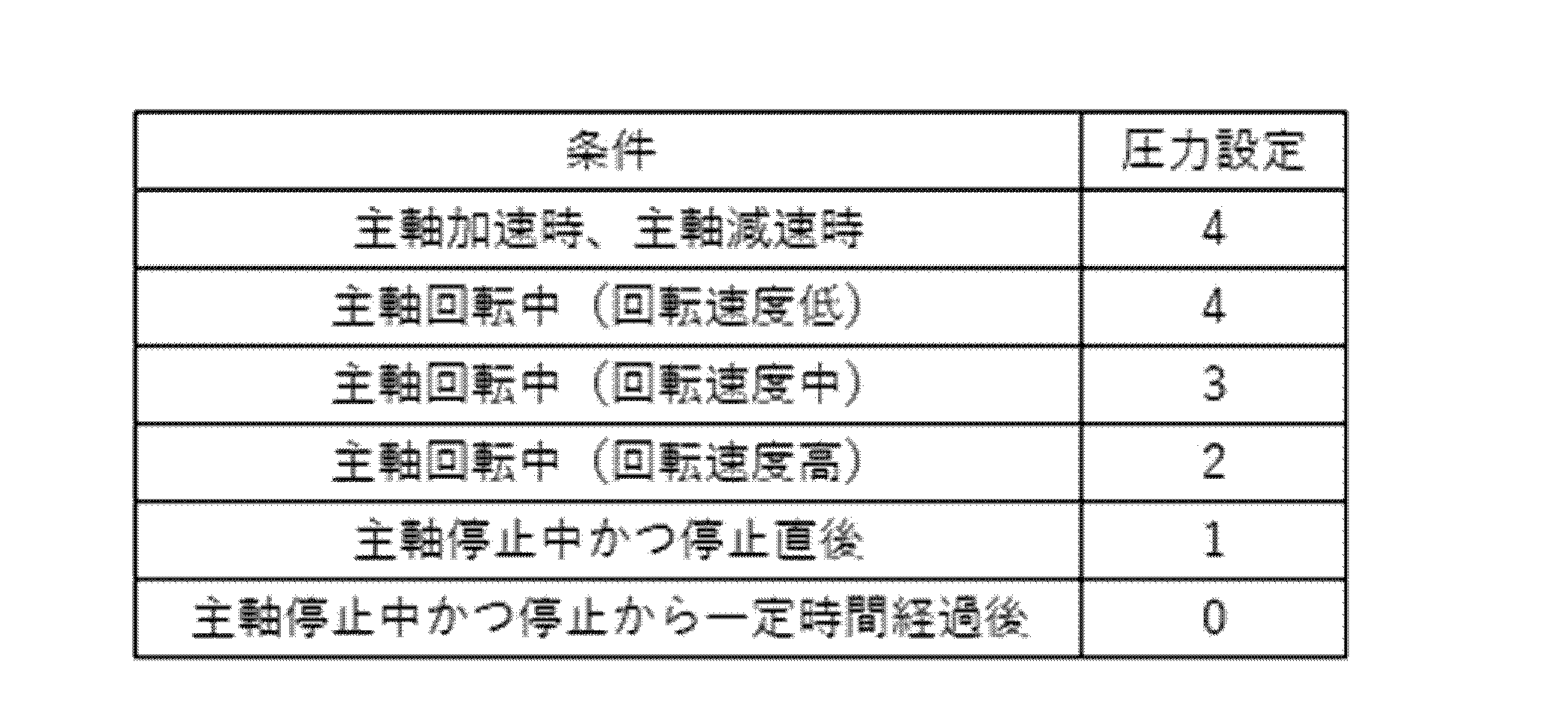
- the supply conditions are set differently depending on the rotation state of the spindle 1, and are associated with the operating conditions input to the input unit 305 and the supply conditions, as shown in the supply condition determination table as related information shown in Table 1, for example.
- Table 1 is an example of a supply condition determination table in which air pressure is set as the supply condition associated with the spindle operating conditions.
- the pressure settings in Table 1 have five levels ranging from "0" for no pressure to "4" for maximum pressure. Note that the pressure settings are not limited to five levels, and may be four levels or less, or six levels or more. The pressure settings are not limited to the settings in Table 1.
- the pressure setting when accelerating or decelerating the spindle 1 is set to the maximum pressure of "4." This is because when the spindle 1 accelerates or decelerates, the internal pressure inside the spindle 1 changes greatly due to centrifugal force, and there is a possibility that the pressure inside the spindle 1 will drop and it will no longer be possible to maintain a positive pressure. If the pressure inside the spindle 1 drops and it is no longer possible to maintain a positive pressure, air will not leak sufficiently through the labyrinth passage 13c, which is a gap, and foreign matter or liquids will enter. This setting increases the pressure of the compressed air supplied to the inside of the spindle 1, thereby preventing the pressure inside the spindle 1 from dropping and no longer being able to maintain a positive pressure.
- the pressure setting is set to a low "2" when the spindle 1 is rotating at a constant speed at high speed. This is because when the spindle 1 is rotating at a constant speed at high speed, even if the internal pressure is low, the air inside the spindle 1 is pushed to the outside of the spindle 1 due to the effect of centrifugal force, and the air leaks sufficiently through the labyrinth passage 13c, which is a gap, to prevent the intrusion of foreign objects or foreign liquids.
- the pressure setting is set to a higher "4". This is because when the spindle 1 is rotating at a constant speed at low speed, the effect of centrifugal force is small and the force pushing the air inside the spindle 1 to the outside of the spindle 1 is reduced, so if the internal pressure is low, air does not leak sufficiently through the labyrinth passage 13c, which is a gap, and foreign matter or liquids enter.
- This setting increases the pressure of the compressed air supplied to the inside of the spindle 1, preventing the pressure inside the spindle 1 from dropping and making it impossible to maintain a positive pressure. For this reason, the internal pressure is set to be higher at low speed rotation than at high speed rotation.
- the pressure setting is set to "3" between high and low speeds. This is because when the spindle 1 is rotating at a constant medium speed, the effect of centrifugal force is about half that of high and low speeds, so by setting the pressure higher than at low speed but lower than at high speed, the intention is to prevent the intrusion of foreign objects or liquids while reducing the consumption of compressed air.
- the pressure setting is set to a low "1" while the spindle 1 is stopped and immediately after it has stopped. This is because it is assumed that the machine tool M is not performing machining while the spindle 1 is stopped and immediately after it has stopped, so the amount of foreign matter or liquid contained in the outside air is small and there is little risk of these entering the inside of the spindle 1.
- the pressure setting is set to "0" while the spindle 1 is stopped and after a predetermined period has elapsed.
- air purging is stopped. This is because while the spindle 1 is stopped and after a predetermined period has elapsed, the mist concentration, including cutting fluid mist, in the outside air drops to a negligible level.
- the predetermined period is, for example, one minute. However, the predetermined period is not limited to one minute.
- the supply condition determination unit 312 determines a lower pressure supply condition as the rotation speed of the spindle 1 increases, and determines a higher pressure supply condition as the rotation speed of the spindle 1 decreases.
- the supply condition determination unit 312 also determines a lower pressure supply condition for a predetermined period of time from immediately after the rotation of the spindle 1 stops.
- the compressed air control unit 313 also stops the operation of the compressed air supply device 2 after a predetermined period of time has elapsed from immediately after the rotation of the spindle 1 stops.
- the pressure of the compressed air to be supplied is set as the supply condition associated with the operating condition, but this is not limited to this.
- the flow rate of the compressed air to be supplied may be set as the supply condition associated with the operating condition.
- the compressed air control unit 313 controls the compressed air supply device 2 based on the supply conditions determined by the supply condition determination unit 312. For example, the compressed air control unit 313 controls the compressed air supply device 2 to supply compressed air at a pressure specified by the supply conditions to the inside of the spindle 1 through the labyrinth seal 13.
- the storage unit 314 reads supply condition determination table information associating the operating conditions and supply conditions shown in Table 1 from the auxiliary storage unit 307 in order for the supply condition determination unit 312 to determine the supply conditions, and stores the information in the processor 300, ROM 301, RAM 302, etc. In addition, the storage unit 314 provides the supply condition determination table information associating the operating conditions and supply conditions to the supply condition determination unit 312 in order for the supply condition determination unit 312 to determine the supply conditions.
- the spindle control unit 315 controls the rotation speed of the spindle 1 to drive the spindle drive unit 14.
- the spindle control unit 315 controls the rotation speed of the spindle 1 to drive the spindle drive unit 14 so that the rotation speed and rotation acceleration are in accordance with the operating conditions acquired by the rotation state information acquisition unit 311.
- FIG. 4 is a flow chart for explaining an example of compressed air supply control by the machine tool control device according to this embodiment.
- a rotation state information acquisition unit 311, a supply condition determination unit 312, a compressed air control unit 313, a storage unit 314, and a spindle control unit 315 function in the processor 300.
- the compressed air supply control is started at the timing when the operating conditions are input to the input unit 305 by the operator of the machine tool M.
- the rotation state information acquisition unit 311 acquires, as rotation state information, information on operating conditions input by the operator to the input unit 305, or information on operating conditions stored in the auxiliary memory unit 307 or memory unit 314 from an operating program that is started in conjunction with an input by the operator to the input unit 305 (step S10).
- the supply condition determination unit 312 determines the supply conditions of the compressed air to be supplied to the inside of the spindle 1 from the operating conditions acquired by the rotation state information acquisition unit 311 and the supply condition determination table information including multiple compressed air supply conditions stored in the memory unit 314 in association with the operating conditions (step S11).
- the compressed air control unit 313 controls the compressed air supply device 2 based on the supply conditions determined by the supply condition determination unit 312 (step S12). That is, the compressed air control unit 313 causes the compressed air supply device 2 to supply compressed air to the inside of the spindle 1 through the labyrinth seal 13 in accordance with the supply conditions determined by the supply condition determination unit 312.
- the compressed air supplied to the spindle 1 can be set to a pressure that corresponds to the rotation state of the spindle shaft 10 of the spindle 1.
- the machine tool control device 3 according to the present embodiment described above provides the following effects.
- the main spindle of the machine tool uses bearings inside to support high-speed rotation, and from the viewpoint of the life of the bearings, it is necessary to prevent foreign matter or liquids from entering the inside of the main spindle.
- the pressure is set in advance regardless of the operating conditions, and depending on the operating conditions, more air may be consumed than necessary. High air consumption results in greater energy consumption by the compressor.
- the air supplied to the inside of the spindle is controlled according to the rotation state of the spindle. Since the amount of air consumed can be kept to the minimum required according to the rotation state of the spindle, it is possible to reduce air consumption compared to the current situation and suppress power consumption throughout the factory.
- the machine tool control device 3 is a machine tool control device 3 that controls a machine tool M having a spindle 1 and a compressed air supply device 2 that supplies compressed air to the inside of the spindle 1, and includes a rotational state information acquisition unit 311 that acquires rotational state information indicating the rotational state of the spindle 1, a supply condition determination unit 312 that determines the supply conditions required for the compressed air to be supplied to the inside of the spindle 1 based on the rotational state information acquired by the rotational state information acquisition unit 311, and a compressed air control unit 313 that controls the compressed air supply device 2 based on the supply conditions determined by the supply condition determination unit 312.
- the machine tool M has an input unit 305 through which the operator inputs operating conditions, the rotational state information acquisition unit 311 acquires the operating conditions input by the operator as rotational state information, and the supply condition determination unit 312 determines the supply conditions required for the compressed air to be supplied to the inside of the spindle 1 based on the rotational state of the spindle 1 according to the operating conditions acquired by the rotational state information acquisition unit 311.
- the operating conditions input by the operator can be used as information on the rotation state of the spindle 1, making control easier while reducing the consumption of compressed air.
- the machine tool control device 3 also includes a memory unit 314 that stores table information for determining supply conditions that associates operating conditions with supply conditions, and the supply condition determination unit 312 determines the supply conditions based on the operating conditions input to the input unit 305 and the table information for determining supply conditions stored in the memory unit 314.
- the rotation state of the spindle 1 includes the state of the rotation speed of the spindle 1.
- the rotation state of the spindle 1 includes the state of the rotation acceleration of the spindle 1.
- the compressed air supply condition determined by the supply condition determination unit 312 is the compressed air pressure.
- the compressed air supply condition determined by the supply condition determination unit 312 is the compressed air flow rate.
- the supply condition determination unit 312 determines a higher pressure supply condition as the rotation speed of the spindle 1 is slower, and determines a lower pressure supply condition as the rotation speed of the spindle 1 is faster.
- the supply condition determination unit 312 determines a lower pressure supply condition for a predetermined period of time from immediately after the rotation of the spindle 1 stops, and the compressed air control unit 313 stops the operation of the compressed air supply device 2 after a predetermined period of time has elapsed from immediately after the rotation of the spindle 1 stops.
- the supply condition determination unit 312 determines the supply conditions necessary for the compressed air to be supplied to the inside of the spindle 1 based on the operating conditions input to the input unit 305 by the operator of the machine tool M as the rotation state information of the spindle 1, but this is not limited to the above.
- the rotation state information acquisition unit 311 may acquire measurement result information indicating the rotation state of the spindle 1 measured by the measuring unit 15 as the rotation state information of the spindle 1.
- the supply condition determination unit 312 may determine the supply conditions necessary for the compressed air to be supplied to the inside of the spindle 1 based on the measurement result information acquired by the rotation state information acquisition unit 311.
- Fig. 5 is a block diagram showing the hardware configuration of the machine tool control device 3 according to the modified example.
- Fig. 6 is a block diagram for explaining the functional configuration of the machine tool control device 3 according to the modified example. Configurations similar to those in the above-mentioned embodiment may be given the same names and detailed descriptions may be omitted.
- the machine tool M is a device having a spindle to which a tool is attached and which is rotated to perform machining.
- the machine tool M has a spindle 1, a compressed air supply device 2, and a machine tool control device 3.
- the spindle 1 has a spindle shaft 10, a plurality of bearings 11, a housing 12, and a labyrinth seal 13 as a non-contact seal structure, and as shown in FIGS. 5 and 6, a spindle drive unit 14 and a measurement unit 15.
- the measuring unit 15 is configured to measure the rotational state of the spindle shaft 10.
- the machine tool M further has a measuring unit 15 capable of measuring the rotational state of the spindle 1.
- the measuring unit 15 is configured, for example, with a rotary encoder capable of measuring the number of rotations, and can measure the rotational speed of the spindle shaft 10.
- the measuring unit 15 may also be capable of measuring the acceleration based on the number of rotations of the spindle shaft 10.
- the machine tool control device 3 includes a processor 300, a ROM 301, a RAM 302, a bus 303, an input/output interface 304, an input unit 305, an output unit 306, an auxiliary storage unit 307, and a power supply 308.
- the control unit 310 of this modified example has a rotation state information acquisition unit (rotation state information acquisition function) 311, a supply condition determination unit (supply condition determination function) 312, a compressed air control unit (compressed air control function) 313, a memory unit (memory function) 314, and a spindle control unit (spindle control function) 315.
- rotation state information acquisition function rotation state information acquisition function
- supply condition determination function supply condition determination function
- compressed air control unit compressed air control function
- memory unit memory function
- spindle control unit spindle control function
- the rotational state information acquisition unit 311 acquires rotational state information indicating the rotational state of the spindle 1.
- the rotational state information acquisition unit 311 in this modified example acquires measurement result information indicating the rotational state of the spindle 1 measured by the measurement unit 15.
- the supply condition determination unit 312 determines the supply conditions based on the rotation state information acquired by the rotation state information acquisition unit 311. For example, the supply condition determination unit 312 in this modified example determines the supply conditions required for the compressed air to be supplied to the inside of the spindle 1 based on the measurement result information acquired by the rotation state information acquisition unit 311.
- threshold values may be set in advance for low, medium, and high speeds and stored in the auxiliary memory unit 307 or the memory unit 314, and the supply condition determination unit 312 may compare the rotation speed measured by the measurement unit 15 with each stored threshold value to identify the operating conditions, and determine the supply conditions based on the identified operating conditions and the supply condition determination table information.
- the supply condition determination unit 312 may also calculate and determine the supply conditions based on the measured rotation speed. For example, a pressure setting or a flow rate setting may be inversely proportional to the measured rotation speed.
- compressed air supply control by the machine tool control device 3 according to this embodiment will be described with reference to Fig. 4.
- a rotation state information acquisition unit 311, a supply condition determination unit 312, a compressed air control unit 313, a storage unit 314, and a spindle control unit 315 function in the processor 300.
- the compressed air supply control is started when the operating conditions are input to the input unit 305 by the operator of the machine tool M.
- the rotational state information acquisition unit 311 acquires measurement result information as rotational state information of the spindle 1 measured by the measurement unit 15 (step S10).
- the supply condition determination unit 312 determines the supply conditions for compressed air to be supplied to the inside of the spindle 1 based on the measurement result information acquired by the rotation state information acquisition unit 311 (step S11).
- the compressed air control unit 313 controls the compressed air supply device 2 based on the supply conditions determined by the supply condition determination unit 312 (step S12). That is, the compressed air control unit 313 causes the compressed air supply device 2 to supply compressed air to the inside of the spindle 1 through the labyrinth seal 13 in accordance with the supply conditions determined by the supply condition determination unit 312.
- the compressed air supplied to the spindle 1 can be set to a pressure that corresponds to the rotation state of the spindle shaft 10 of the spindle 1.
- the machine tool M further includes a measuring unit 15 capable of measuring the rotational state of the spindle 1, the rotational state information acquisition unit 311 acquires measurement result information indicating the rotational state of the spindle 1 measured by the measuring unit 15 as rotational state information, and the supply condition determination unit 312 determines the supply conditions required for the compressed air to be supplied to the inside of the spindle 1 based on the measurement result information acquired by the rotational state information acquisition unit 311.
- the series of processes relating to the above-mentioned method can be executed by hardware or software.
- the functional configurations of Figures 3 and 6 are merely examples and are not particularly limited. In other words, it is sufficient if the function capable of executing the series of processes described above as a whole is provided, and the type of functional block used to realize this function is not particularly limited to the examples of Figures 3 and 6.
- one functional block may be configured as a single piece of hardware, a single piece of software, or a combination of both.
- the functional configuration in this embodiment is realized by a processor that executes arithmetic processing, and processors that can be used in this embodiment include those configured as single processing devices such as single processors, multiprocessors, and multicore processors, as well as those that combine these various processing devices with processing circuits such as ASICs (Application Specific Integrated Circuits) and FPGAs (Field-Programmable Gate Arrays).
- ASICs Application Specific Integrated Circuits
- FPGAs Field-Programmable Gate Arrays
- the computer may be a computer that is built into dedicated hardware.
- the computer may also be a computer that is capable of executing various functions by installing various programs, such as a general-purpose personal computer.
- Recording media containing such programs are not only composed of removable media distributed separately from the device body in order to provide the user with the program, but also composed of recording media provided to the user in a state where the program is already installed in the device body.
- Removable media are, for example, magnetic disks (including floppy disks), optical disks, or magneto-optical disks.
- Optical disks are, for example, CD-ROMs (Compact Disk-Read Only Memory), DVDs (Digital Versatile Disks), Blu-ray (registered trademark) Discs, etc.
- Magneto-optical disks are, for example, MDs (Mini-Disks), etc.
- Recording media provided to the user in a state where the program is already installed in the device body are, for example, the ROM in Figures 2 and 5 in which the program is recorded, or the hard disk included in the auxiliary storage unit in Figures 2 and 5.
- the steps describing the program to be recorded on the recording medium include not only processes that are performed chronologically according to the order, but also processes that are not necessarily performed chronologically but are executed in parallel or individually.
- a machine tool control device that controls a machine tool having a spindle and a compressed air supply device that supplies compressed air to an inside of the spindle, a rotation state information acquisition unit that acquires rotation state information indicating a rotation state of the spindle; a supply condition determination unit that determines necessary supply conditions for compressed air to be supplied to an inside of the spindle based on the rotation state information acquired by the rotation state information acquisition unit; a compressed air control unit that controls the compressed air supply device based on the supply conditions determined by the supply condition determination unit.
- the machine tool has an operation input unit through which an operator inputs operation conditions, the rotation state information acquisition unit acquires operating conditions input by the operator as the rotation state information;
- the machine tool control device described in Appendix 1 wherein the supply condition determination unit determines the supply conditions required for compressed air to be supplied inside the spindle based on the rotational state of the spindle due to the operating conditions acquired by the rotational state information acquisition unit.
- Appendix 3 A machine tool control device as described in Appendix 2, further comprising a memory unit that stores associated information correlating the operating conditions and the supply conditions, and the supply condition determination unit determines the supply conditions based on the operating conditions input to the operation input unit and the associated information stored in the memory unit.
- the machine tool further includes a measurement unit capable of measuring a rotation state of the spindle, the rotation state information acquisition unit acquires, as the rotation state information, measurement result information indicating the rotation state of the spindle measured by the measurement unit;
- the machine tool control device described in Appendix 1 wherein the supply condition determination unit determines the supply conditions required for the compressed air to be supplied inside the spindle based on the measurement result information acquired by the rotational state information acquisition unit.
- the rotation state of the spindle includes a state of a rotation speed of the spindle.
- the machine tool control device includes a state of rotational acceleration of the spindle.
- (Appendix 7) 7.
- the supply condition of compressed air determined by the supply condition determination unit is a pressure of the compressed air.
- (Appendix 8) 8.
- the machine tool control device according to claim 1, wherein the supply condition of compressed air determined by the supply condition determination unit is a flow rate of compressed air.
- the supply condition determination unit is The faster the rotation speed of the spindle is, the lower the pressure of the supply condition is determined;
- the machine tool control device according to any one of appendices 5 to 7, wherein the supply condition is determined to be a higher pressure as the rotation speed of the spindle is slower.
- the supply condition determination unit determines the supply condition to be a lower pressure for a predetermined period of time immediately after the rotation of the spindle is stopped, 10.
- the compressed air control unit stops operation of the compressed air supply device immediately after the rotation of the spindle stops and after the predetermined period of time has elapsed.
- Machine tool 1 Spindle 2 Compressed air supply device 3 Machine tool control device 311 Rotation state information acquisition unit 312 Supply condition determination unit 313 Compressed air control unit
Landscapes
- Engineering & Computer Science (AREA)
- General Engineering & Computer Science (AREA)
- Mechanical Engineering (AREA)
- Human Computer Interaction (AREA)
- Manufacturing & Machinery (AREA)
- Physics & Mathematics (AREA)
- General Physics & Mathematics (AREA)
- Automation & Control Theory (AREA)
- Machine Tool Sensing Apparatuses (AREA)
- Fluid-Pressure Circuits (AREA)
- Control Of Positive-Displacement Pumps (AREA)
Abstract
圧縮空気の消費量を抑えることができる工作機械制御装の提供を目的とする。工作機械制御装置3は、主軸1と、主軸1の内部に圧縮空気を供給する圧縮空気供給装置2と、を有する工作機械Mを制御する工作機械制御装置3であって、主軸1の回転状態を示す回転状態情報を取得する回転状態情報取得部311と、回転状態情報取得部311が取得した回転状態情報に基づいて、主軸1の内部に供給する圧縮空気に必要な供給条件を決定する供給条件決定部312と、供給条件決定部312が決定した供給条件に基づいて圧縮空気供給装置2を制御する圧縮空気制御部313と、を備える。
Description
本開示は、工作機械制御装置に関する。
従来、工作機械の主軸は、高速回転を支持するために内部に軸受を使用しており、軸受の寿命の観点から異物や異液の主軸内部への侵入を防ぐ必要がある。しかしながら、高速回転しているという性質から、接触部を持つシールを使用することができないため、ラビリンスシールと呼ばれる非接触シール構造を設け、かつ主軸内部に清浄なエアを導入して正圧に保つことにより(エアパージ)異物や異液の侵入を防止する技術が知られている(特許文献1)。
ところで、主軸内部を正圧に保つために導入(供給)されるエア(圧縮空気)として予め設定した一定の供給条件の圧縮空気が用いられる。しかしながら、動作条件によって要求される供給条件が異なることから必要以上に圧縮空気を消費するおそれがあった。
圧縮空気の消費量を抑えることができる工作機械制御装置の提供を目的とする。
本開示の一態様は、主軸と、前記主軸の内部に圧縮空気を供給する圧縮空気供給装置と、を有する工作機械を制御する工作機械制御装置であって、前記主軸の回転状態を示す回転状態情報を取得する回転状態情報取得部と、前記回転状態情報取得部が取得した前記回転状態情報に基づいて、前記主軸の内部に供給する圧縮空気に必要な供給条件を決定する供給条件決定部と、前記供給条件決定部が決定した前記供給条件に基づいて前記圧縮空気供給装置を制御する圧縮空気制御部と、を備える、工作機械制御装置である。
<工作機械>
本実施形態に係る工作機械Mの構成について、図1~図3を用いて説明する。図1は、本実施形態に係る工作機械Mの主軸1周りの一例を示す模式図である。図2は、本実施形態に係る工作機械制御装置3のハードウェア構成を示すブロック図である。図3は、本実施形態に係る工作機械制御装置3の機能的構成を説明するためのブロック図である。
本実施形態に係る工作機械Mの構成について、図1~図3を用いて説明する。図1は、本実施形態に係る工作機械Mの主軸1周りの一例を示す模式図である。図2は、本実施形態に係る工作機械制御装置3のハードウェア構成を示すブロック図である。図3は、本実施形態に係る工作機械制御装置3の機能的構成を説明するためのブロック図である。
<工作機械>
工作機械Mは、工具を装着し、回転駆動して加工を行うための主軸を有する装置である。工作機械Mは、主軸1と、圧縮空気供給装置2と、工作機械制御装置3と、を有する。
工作機械Mは、工具を装着し、回転駆動して加工を行うための主軸を有する装置である。工作機械Mは、主軸1と、圧縮空気供給装置2と、工作機械制御装置3と、を有する。
主軸1は、工作機械Mにおける加工のための動力を回転して伝えるための装置である。主軸1は、各種の工作機械に用いることができる。詳細は、後述する。
圧縮空気供給装置2は、主軸1の内部に圧縮空気を供給するための構成である。本実施形態に係る圧縮空気供給装置2は、後述の非接触シール構造としてのラビリンスシール13を介して主軸1の内部へ圧縮空気を供給する。圧縮空気供給装置2は、例えばポンプである。なお、圧縮空気供給装置2は、ポンプに限定されない。例えば、工場全体の設備の共通のコンプレッサでもよい。
工作機械制御装置3は、工作機械Mの各種の動作を制御するための構成である。詳細は、後述する。
<主軸周りのハードウェア構成>
本実施形態に係る工作機械Mに備わる主軸1の構成について、図1~図3を用いて説明する。主軸1は、図1に示されるように、主軸シャフト10と、複数の軸受11と、ハウジング12と、非接触シール構造としてのラビリンスシール13と、図2、図3に示されるように、主軸駆動部14と、を有する。
本実施形態に係る工作機械Mに備わる主軸1の構成について、図1~図3を用いて説明する。主軸1は、図1に示されるように、主軸シャフト10と、複数の軸受11と、ハウジング12と、非接触シール構造としてのラビリンスシール13と、図2、図3に示されるように、主軸駆動部14と、を有する。
主軸シャフト10は、工作機械Mにおける加工部に駆動部の動力を伝達させるための円柱形状部材である。主軸シャフト10は、図1に示されるように、主軸シャフト10の外周面にストッパー10aが固定されている。ストッパー10aは、主軸シャフト10の軸方向において、ハウジング12に対する主軸シャフト10の移動を規制するための構成である。主軸シャフト10は、ハウジング12の内部に位置決めされた軸受11にストッパー10aが接することで主軸シャフト10の軸方向への移動が規制される。ストッパー10aは、例えば内周面が主軸シャフト10の外周面に接するように形成される円環状部材でもよい。また、ストッパー10aの形状は、円環状部材に限定されない。
軸受11は、主軸シャフト10を回転可能に保持するための構成である。軸受11は、外輪と、内輪と、複数のボールと、を有する。外輪は、ハウジング12に固定される。内輪は、主軸シャフト10に締り嵌めで嵌合されており、外輪に対して相対的に回転する。複数のボールは、軸方向に直交する環状に配列して外輪と内輪との間に介在することで、外輪に対して内輪が相対的に回転することを可能にする。このような軸受11は、ハウジング12に対して主軸シャフト10を支持するとともに、ハウジング12に対して主軸シャフト10が回転することを可能にする。
なお、本実施形態に係る主軸1は、不図示の2つの軸受11も含め、計4つの軸受11を有するが、これに限らない。例えば、主軸1は、3つ以下の軸受11を有してもよいし、5つ以上の軸受11を有してもよい。
ハウジング12は、両端側に開口部を有し、主軸シャフト10等を収容可能な円筒形部材である。ハウジング12は、円筒形状の開口部から主軸シャフト10が突出するように主軸シャフト10及び軸受11を内部に収容する。ハウジング12は、図1に示されるように、ハウジング12の内周面にストッパー12aが固定されている。ストッパー12aは、主軸シャフトの軸方向において、ハウジング12に対する軸受11の移動を規制するための構成である。軸受11は、ハウジング12の内周面のストッパー10aに軸受11が接することで主軸シャフト10の軸方向への移動が規制される。
ラビリンスシール13は、ハウジング12内への異物や異液の侵入を抑制するための非接触シール構造である。工作機械Mは、主軸1が高速回転していることから耐久性の観点から非接触シール構造としてのラビリンスシール13が採用されている。ラビリンスシール13は、ハウジング12の両端側の開口部と主軸シャフト10との間を埋めるように設けられる。図1には、ハウジング12の両端側のうちの一端側において、ラビリンスシール13が設けられる状態が示される。
ラビリンスシール13は、主軸シャフト10に固定して配置された円環状の内側シール13aと、内側シール13aと対向して配置され、内側シール13aの外側において非接触状態でハウジング12側においてハウジング12に固定して配置された円環状の外側シール13bとを備える。
ラビリンスシール13は、主軸1の内部に圧縮空気Aを供給するエアパージを行うことができるように構成される。具体的には、ラビリンスシール13は、ラビリンスシール13の内部に圧縮空気Aを供給するために、外側シール13bに、ラビリンスシール13の外部と内部とが連通する空気の流路であるエアパージ部13b1を有する。上述の圧縮空気供給装置2がエアパージ部13b1を介して主軸1の内部に圧縮空気Aを供給することで、エアパージが行われる。また、ラビリンスシール13は、内側シール13aと外側シール13bとの間の隙間であって主軸の内部にある空気の外部への流路であるラビリンス通路13cを有し、当該ラビリンス通路13cから主軸1の内部の空気が漏れる。従って、主軸1は、エアパージにより主軸1の内部を主軸1の外部の切削液ミストを含む外気に対して正圧に保つことで、主軸1の内部の空気をラビリンスシール13の隙間としてのラビリンス通路13cから漏らすことができ、当該隙間からの粉塵等の異物や液体の侵入を防ぐことができる。
主軸駆動部14は、主軸シャフト10を回転させるための構成である。主軸駆動部14は、例えば不図示のモータ等により主軸シャフト10を回転させる。
<工作機械制御装置のハードウェア構成>
次に、本発明の一実施形態に係る工作機械制御装置3のハードウェア構成の一例について、図2を用いて説明する。工作機械制御装置3は、図2に示すように、プロセッサ300と、ROM(Read Only Memory)301と、RAM(Random Access Memory)302と、バス303と、入出力インターフェース304と、入力部305と、出力部306と、補助記憶部307と、電源308と、を備えている。
次に、本発明の一実施形態に係る工作機械制御装置3のハードウェア構成の一例について、図2を用いて説明する。工作機械制御装置3は、図2に示すように、プロセッサ300と、ROM(Read Only Memory)301と、RAM(Random Access Memory)302と、バス303と、入出力インターフェース304と、入力部305と、出力部306と、補助記憶部307と、電源308と、を備えている。
プロセッサ300は、工作機械Mの動作に必要な演算及び制御等の処理を行うコンピュータの中枢部分であり、各種演算及び処理等を行う。プロセッサ300は、例えば、CPU(Central Processing Unit)、MPU(Micro Processing Unit)、SoC(System on a Chip)、DSP(Digital Signal Processor)、GPU(Graphics Processing Unit)、ASIC(Application Specific Integrated Circuit)、PLD(Programmable Logic Device)又はFPGA(Field-Programmable Gate Array)等である。或いは、プロセッサ300は、これらのうちの複数を組み合わせたものである。また、プロセッサ300は、これらにハードウェアアクセラレーター等を組み合わせたものあってもよい。
プロセッサ300は、ROM301又はRAM302等に記憶されたファームウェア、システムソフトウェア及びアプリケーションソフトウェア等のプログラムに基づいて、工作機械制御装置3の各種の機能を実現するべく各部を制御する。また、プロセッサ300は、プログラムに基づく処理を実行する。なお、当該プログラムの一部又は全部は、プロセッサ300の回路内に組み込まれていてもよい。
プロセッサ300、ROM301及びRAM302は、バス303を介して相互に接続されている。このバス303にはまた、入出力インターフェース304も接続されている。入出力インターフェース304には、入力部305、出力部306、補助記憶部307、電源308が接続されている。
入力部305及び出力部306は、有線又は無線により電気的に入出力インターフェース304に接続されるユーザインターフェースである。入力部305は、例えば操作ボタン等で構成され、ユーザの指示操作に応じて各種情報を入力する。出力部306は、画像を表示するディスプレイや音声を拡声するスピーカ等で構成され、画像や音声を出力する。なお、本実施形態に係る入力部305は、工作機械Mの操作者による動作条件入力装置として機能する。即ち、工作機械Mは、操作者が動作条件を入力するための入力部305を有する。
ここで、動作条件とは、主軸1の回転を操作するための情報である。例えば、動作条件は、主軸1を所定の回転速度で回転させるための指令情報である。本実施形態では、3段階の回転速度が選択できるように3段階の回転速度毎の動作条件が設定される。具体的には、動作条件は、低い回転速度から順に、低速、中速、高速の3段階が設定される。なお、動作情報は、これに限らない。
また、動作条件は、主軸1の等速回転までの加速時、又は回転が停止するまでの減速時の回転加速度を指令する情報でもよい。例えば、この場合、主軸1は、動作条件入力装置に入力された動作条件に規定された回転加速度となるように加減速が行われる。
なお、本実施形態では、入力部305が動作条件入力装置を兼ねるが、これに限らず、動作条件入力装置は、入力部305とは別に設けてもよい。また、本実施形態では、動作条件は、操作者の入力部305への入力により取得されるが、これに限らず、例えば後述の補助記憶部307に保存された動作プログラムから、工作機械Mの動作条件を取得してもよい。
補助記憶部307は、HDD(Hard Disk Drive)、SSD(Solid State Drive)等で構成される補助記憶装置である。補助記憶部307は、各種の処理に関するプログラムや設定値等の各種の情報を記憶する。補助記憶部307は、例えば後述の工作機械Mの操作者に入力された動作条件や、後述する動作条件に関連付けられた圧縮空気の供給条件についての供給条件決定用テーブル情報、各種のプログラム等を記憶する。
電源308は、外部の電源に接続されることにより、工作機械制御装置3の各部に電力を供給可能に構成される。なお、電源に電力を供給可能な構成はこれに限らず、例えばバッテリでもよい。
<工作機械制御装置の機能的構成>
次に、工作機械制御装置3の機能的構成について、図3を用いて説明する。工作機械制御装置3の各種の制御を行う制御部310は、演算処理を実行する後述するプロセッサ300がROM301、RAM302、補助記憶部307等に記憶されたプログラムを実行することによって実現される。
次に、工作機械制御装置3の機能的構成について、図3を用いて説明する。工作機械制御装置3の各種の制御を行う制御部310は、演算処理を実行する後述するプロセッサ300がROM301、RAM302、補助記憶部307等に記憶されたプログラムを実行することによって実現される。
本実施形態の制御部310は、回転状態情報取得部(回転状態情報取得機能)311と、供給条件決定部(供給条件決定機能)312と、圧縮空気制御部(圧縮空気制御機能)313と、記憶部(記憶機能)314と、主軸制御部(主軸制御機能)315と、を有する。
回転状態情報取得部311は、主軸1の回転状態を示す回転状態情報を取得する。即ち、回転状態情報とは、主軸1の回転状態を示す情報である。回転状態情報は、例えば主軸1の回転速度の状態を含んでもよい。また、回転状態情報は、例えば主軸1の回転加速度の状態を含んでもよい。本実施形態に係る回転状態情報は、動作条件である。即ち、回転状態情報取得部311は、動作条件取得部として機能する。本実施形態では、主軸1は、動作条件に沿って動作することから、動作条件は、回転状態情報として活用可能である。
供給条件決定部312は、回転状態情報取得部311が取得した回転状態情報に基づいて、供給条件を決定する。本実施形態に係る供給条件決定部312は、主軸1の内部に供給する圧縮空気に必要な供給条件を回転状態情報取得部311が取得した動作条件による主軸1の回転状態を基に決定する。
供給条件とは、主軸1の内部に供給する圧縮空気に必要な情報である。本実施形態に係る供給条件は、例えば主軸1の内部に供給する圧縮空気の圧力である。即ち、供給条件決定部312が決定する圧縮空気の供給条件は、圧縮空気の圧力である。
なお、供給条件は、例えば主軸1の内部に供給する圧縮空気の流量でもよい。即ち、供給条件決定部312が決定する圧縮空気の供給条件は、圧縮空気の流量である。
本実施形態では、供給条件は、主軸1の回転状態により異なる設定とし、例えば表1に示される関連情報としての供給条件決定用テーブルに示されるように、入力部305に入力された動作条件と、供給条件と、に関連付けている。表1は、主軸の動作条件に関連付けられた供給条件としての空気圧力が設定された供給条件決定用テーブルの例である。表1における圧力設定は、圧力をかけない「0」~圧力最大の「4」迄の5段階としている。なお、圧力設定は、5段階に限らず、4段階以下にしてもよいし、6段階以上としてもよい。また、圧力設定は、表1の設定に限定されない。
例えば、動作条件として、主軸1の加速時、又は減速時の圧力設定を最大圧力の「4」としている。これは、主軸1の加速時、又は減速時は、主軸1の内部における遠心力に伴う内圧の変化が大きいため、主軸1の内部の圧力が下がって正圧に保てなくなる可能性がある。主軸1の内部の圧力が下がって正圧に保てなくなると、空気が隙間であるラビリンス通路13cより十分に漏れず、異物や異液が侵入してしまう。本設定は、主軸1の内部に供給する圧縮空気の圧力を高めることで、主軸1の内部の圧力が下がって正圧に保てなくなることを抑制する。
また、動作条件として、主軸1の高速での等速回転中は、圧力設定を低めの「2」に設定している。これは、主軸1の高速での等速回転中は、内圧が低くても遠心力の効果で主軸1の内部の空気が主軸1の外側に押し出され、空気が隙間であるラビリンス通路13cより十分に漏れ、異物や異液の侵入を防ぐことができるためである。
一方、動作条件として、主軸1の低速での等速回転中は、圧力設定を高めの「4」に設定している。これは、主軸1の低速での等速回転中は、遠心力の影響が少なく主軸1の内部の空気を主軸1の外側に押し出す力が減少するため、内圧が低いと空気が隙間であるラビリンス通路13cより十分に漏れず、異物や異液が侵入してしまう。本設定は、主軸1の内部に供給する圧縮空気の圧力を高めることで、主軸1の内部の圧力が下がって正圧に保てなくなることを抑制する。そのため、高速回転時より低速回転時に内圧が高くなるように設定される。
また、動作条件として、主軸1の中速での等速回転中は、圧力設定は高速と低速の間の「3」に設定している。これは、主軸1の中速での等速回転中は、遠心力の影響が高速と低速との間の半分程度であるため、低速よりも圧力を高めにしつつ、高速よりも抑えることで、異物や異液が侵入することを予防しつつ、圧縮空気の消費量を削減することを意図している。
また、動作条件として、主軸1の停止中かつ停止直後は、圧力設定を低めの「1」に設定している。これは、主軸1の停止中かつ停止直後は、工作機械Mは、加工を実施していないと推測されるため、外気に含まれる異物や異液の量が少なく、主軸1の内部への侵入のおそれが低いためである。
また、動作条件として、主軸1の停止中かつ所定期間経過後は、圧力設定を「0」に設定する。即ち、主軸1の停止中かつ所定期間経過後は、エアパージを停止する。これは、主軸1の停止中かつ所定期間経過後は、外気の切削液ミストを含むミスト濃度が無視できるレベルに下がるためである。所定期間は、例えば1分間である。しかし、所定期間は、1分間に限らない。
このような供給条件決定用テーブルとすることで、供給条件決定部312は、主軸1の回転速度が速いほど、低い圧力の供給条件に決定し、主軸1の回転速度が遅いほど、高い圧力の供給条件に決定する。また、供給条件決定部312は、主軸1の回転が停止した直後から所定期間の間、より低い圧力の供給条件に決定する。また、圧縮空気制御部313は、主軸1の回転が停止した直後から所定期間経過後に、圧縮空気供給装置2の動作を停止させる。
なお、本実施形態では、動作条件に関連付けられた供給条件として供給する圧縮空気の圧力を設定したが、これに限らない。例えば、動作条件に関連付けられた供給条件として供給する圧縮空気の流量を設定してもよい。
圧縮空気制御部313は、供給条件決定部312が決定した供給条件に基づいて圧縮空気供給装置2を制御する。例えば、圧縮空気制御部313は、圧縮空気供給装置2に、供給条件より特定される圧力の圧縮空気をラビリンスシール13を介して主軸1の内部に供給させるよう制御する。
記憶部314は、供給条件決定部312による供給条件決定のために、表1に示される、動作条件と、供給条件と、に関連付けた関連情報としての供給条件決定用テーブル情報を補助記憶部307から読み込み、プロセッサ300、ROM301、RAM302等に記憶する。また、記憶部314は、供給条件決定部312による供給条件決定のために、供給条件決定部312に動作条件と、供給条件と、に関連付けた供給条件決定用テーブル情報を提供する。
主軸制御部315は、主軸1の回転数を制御して主軸駆動部14を駆動させる。例えば、主軸制御部315は、回転状態情報取得部311が取得した動作条件に沿った回転速度、回転加速度となるように、主軸1の回転数を制御して主軸駆動部14を駆動させる。
<圧縮空気供給制御>
次に、本実施形態に係る工作機械制御装置3による圧縮空気供給制御について、図4を用いて説明する。図4は、本実施形態に係る工作機械制御装置による圧縮空気供給制御の一例を説明するためのフローチャートである。本実施形態に係る工作機械制御装置3は、圧縮空気供給制御実行時に、プロセッサ300において、回転状態情報取得部311と、供給条件決定部312と、圧縮空気制御部313と、記憶部314と、主軸制御部315と、が機能する。圧縮空気供給制御は、工作機械Mの操作者により入力部305に動作条件が入力されたタイミングで開始される。
次に、本実施形態に係る工作機械制御装置3による圧縮空気供給制御について、図4を用いて説明する。図4は、本実施形態に係る工作機械制御装置による圧縮空気供給制御の一例を説明するためのフローチャートである。本実施形態に係る工作機械制御装置3は、圧縮空気供給制御実行時に、プロセッサ300において、回転状態情報取得部311と、供給条件決定部312と、圧縮空気制御部313と、記憶部314と、主軸制御部315と、が機能する。圧縮空気供給制御は、工作機械Mの操作者により入力部305に動作条件が入力されたタイミングで開始される。
まず、回転状態情報取得部311は、操作者の入力部305へ入力した動作条件の情報、或いは補助記憶部307又は記憶部314に保存され、操作者の入力部305への入力に連動して起動した動作プログラムから動作条件の情報を回転状態情報として取得する(ステップS10)。
次に、供給条件決定部312は、回転状態情報取得部311が取得した動作条件と、記憶部314に動作条件に関連付けて保存された圧縮空気の複数の供給条件を含む供給条件決定用テーブル情報と、から主軸1の内部に供給する圧縮空気の供給条件を決定する(ステップS11)。
次に、供給条件決定部312が決定した供給条件をもとに、圧縮空気制御部313が圧縮空気供給装置2を制御する(ステップS12)。即ち、圧縮空気制御部313は、供給条件決定部312が決定した供給条件に沿うように圧縮空気供給装置2にラビリンスシール13を介して主軸1の内部に圧縮空気を供給させる。
上述のように、主軸シャフト10の回転状態に応じて、主軸1への異物や異液の侵入を抑制するのに必要な圧力は異なるが、本実施形態に係る工作機械Mでは、主軸1に供給される圧縮空気は、主軸1の主軸シャフト10の回転状態に応じた圧力に設定できる。
以上説明した本実施形態に係る工作機械制御装置3によれば、以下の効果が得られる。工作機械の主軸は高速回転を支持するために内部に軸受を使用しており、軸受の寿命を観点から異物や異液の主軸内部への浸入を防ぐ必要がある。
しかしながら、高速回転しているという性質から、接触部を持つシールを使用することができないため、ラビリンスシールと呼ばれる非接触シール構造を設け、かつ主軸内部に清浄なエアを導入するエアパージによって主軸内部を正圧に保つことにより、異物や異液の浸入を防止している。主軸内部を正圧に保つためには圧縮空気を使用する必要があり、圧縮空気を生成するためにはコンプレッサが必要になる。
エアパージを実施する場合は動作条件によらず予め設定した圧力となっており、動作条件によっては必要以上にエアを消費している可能性がある。エア消費が多いとコンプレッサによる消費エネルギーが大きくなる。
主軸の回転状態に応じて、主軸内部に供給するエアを制御する。主軸の回転状態に応じて必要最低限のエア消費量とすることができるため、現状にくらべてエア消費量を削減することができ、工場全体の消費電力を抑えることができる。
本実施形態に係る工作機械制御装置3は、主軸1と、主軸1の内部に圧縮空気を供給する圧縮空気供給装置2と、を有する工作機械Mを制御する工作機械制御装置3であって、主軸1の回転状態を示す回転状態情報を取得する回転状態情報取得部311と、回転状態情報取得部311が取得した回転状態情報に基づいて、主軸1の内部に供給する圧縮空気に必要な供給条件を決定する供給条件決定部312と、供給条件決定部312が決定した供給条件に基づいて圧縮空気供給装置2を制御する圧縮空気制御部313と、を備える。
これにより、主軸1の内部に供給する圧縮空気の消費量を抑えることができる。
また、本実施形態に係る工作機械制御装置3においては、工作機械Mは、操作者が動作条件を入力するための入力部305を有し、回転状態情報取得部311は、操作者により入力された動作条件を回転状態情報として取得し、供給条件決定部312は、主軸1の内部に供給する圧縮空気に必要な供給条件を回転状態情報取得部311が取得した動作条件による主軸1の回転状態を基に決定する。
これにより、操作者により入力される動作条件を主軸1の回転状態情報として活用できるため、制御を容易としつつ圧縮空気の消費量を抑えることができる。
また、本実施形態に係る工作機械制御装置3は、動作条件と、供給条件と、を関連づけた供給条件決定用テーブル情報を記憶する記憶部314を備え、供給条件決定部312は、入力部305に入力された動作条件と、記憶部314に記憶された供給条件決定用テーブル情報と、に基づき、供給条件を決定する。
これにより、動作条件と供給条件とが関連付けられたテーブルに沿って供給条件を決定することができるため、制御を容易としつつ圧縮空気の消費量を抑えることができる。
また、本実施形態に係る工作機械制御装置3は、主軸1の回転状態は、主軸1の回転速度の状態を含む。
これにより、回転状態情報として回転速度の情報を活用できるため、制御を容易としつつ圧縮空気の消費量を抑えることができる。
また、本実施形態に係る工作機械制御装置3は、主軸1の回転状態は、主軸1の回転加速度の状態を含む。
これにより、回転状態情報として回転加速度の情報を活用できるため、制御を容易としつつ圧縮空気の消費量を抑えることができる。
また、本実施形態に係る工作機械制御装置3は、供給条件決定部312が決定する圧縮空気の供給条件は、圧縮空気の圧力である。
これにより、供給条件として圧縮空気供給装置2の圧縮空気の供給圧力情報をそのまま活用できるため、制御を容易でき圧縮空気の消費量を抑えることができる。
また、本実施形態に係る工作機械制御装置3は、供給条件決定部312が決定する圧縮空気の供給条件は、圧縮空気の流量である。
これにより、供給条件として圧縮空気供給装置2の圧縮空気の供給流量情報をそのまま活用できるため、より容易に圧縮空気の消費量を抑えることができる。
また、本実施形態に係る工作機械制御装置3は、供給条件決定部312は、主軸1の回転速度が遅いほど、高い圧力の供給条件に決定し、主軸1の回転速度が速いほど、低い圧力の供給条件に決定する。
これにより、主軸1の回転による内部の空気にかかる遠心力によって不要となる分の圧縮空気の圧力を減らすことができ、より容易に圧縮空気の消費量を抑えることができる。
また、本実施形態に係る工作機械制御装置3は、供給条件決定部312は、主軸1の回転が停止した直後から所定期間の間、より低い圧力の供給条件に決定し、圧縮空気制御部313は、主軸1の回転が停止した直後から所定期間経過後に、圧縮空気供給装置2の動作を停止させる。
これにより、主軸1の停止直後の加工を実施していないと推測されるときに、外気に含まれる異物や異液の量が少ない場合に、不必要に圧縮空気を消費せずに済む。また、主軸1の停止中かつ所定期間経過後、外気の切削液ミストを含むミスト濃度が無視できるレベルに下がった場合に、不必要に圧縮空気を消費せずに済む。このため、より容易に圧縮空気の消費量を抑えることができる。
<変形例>
なお、上述の実施形態では、供給条件決定部312は、主軸1の回転状態情報として工作機械Mの操作者により入力部305に入力された動作条件に基づいて、主軸1の内部に供給する圧縮空気に必要な供給条件を決定していたが、これに限らない。例えば、工作機械Mが主軸1の回転状態を測定可能な後述する測定部15を更に有する場合、回転状態情報取得部311は、主軸1の回転状態情報として測定部15が測定した主軸1の回転状態を示す測定結果情報を取得してもよい。また、供給条件決定部312は、主軸1の内部に供給する圧縮空気に必要な供給条件を回転状態情報取得部311が取得した測定結果情報を基に決定してもよい。
なお、上述の実施形態では、供給条件決定部312は、主軸1の回転状態情報として工作機械Mの操作者により入力部305に入力された動作条件に基づいて、主軸1の内部に供給する圧縮空気に必要な供給条件を決定していたが、これに限らない。例えば、工作機械Mが主軸1の回転状態を測定可能な後述する測定部15を更に有する場合、回転状態情報取得部311は、主軸1の回転状態情報として測定部15が測定した主軸1の回転状態を示す測定結果情報を取得してもよい。また、供給条件決定部312は、主軸1の内部に供給する圧縮空気に必要な供給条件を回転状態情報取得部311が取得した測定結果情報を基に決定してもよい。
以下に、上記変形例に係る工作機械Mについて、図1、図4~図6を用いて説明する。図5は、変形例に係る工作機械制御装置3のハードウェア構成を示すブロック図である。図6は、変形例に係る工作機械制御装置3の機能的構成を説明するためのブロック図である。上述の実施形態と同様の構成については、同じ名称を付して詳細な説明を省略する場合がある。
<工作機械>
工作機械Mは、工具を装着し、回転駆動して加工を行うための主軸を有する装置である。工作機械Mは、主軸1と、圧縮空気供給装置2と、工作機械制御装置3と、を有する。
工作機械Mは、工具を装着し、回転駆動して加工を行うための主軸を有する装置である。工作機械Mは、主軸1と、圧縮空気供給装置2と、工作機械制御装置3と、を有する。
<主軸周りのハードウェア構成>
主軸1は、図1に示されるように、主軸シャフト10と、複数の軸受11と、ハウジング12と、非接触シール構造としてのラビリンスシール13と、図5、図6に示されるように、主軸駆動部14と、測定部15と、を有する。
主軸1は、図1に示されるように、主軸シャフト10と、複数の軸受11と、ハウジング12と、非接触シール構造としてのラビリンスシール13と、図5、図6に示されるように、主軸駆動部14と、測定部15と、を有する。
測定部15は、主軸シャフト10の回転状態を測定するための構成である。言い換えると、工作機械Mは、主軸1の回転状態を測定可能な測定部15を更に有する。測定部15は、例えば回転数を測定可能なロータリエンコーダ等により構成され、主軸シャフト10の回転速度を測定できる。また、測定部15は、主軸シャフト10の回転数に基づき加速度を測定できてもよい。
<工作機械制御装置のハードウェア構成>
次に、本変形例に係る工作機械制御装置3のハードウェア構成の一例について、図5を用いて説明する。工作機械制御装置3は、図5に示すように、プロセッサ300と、ROM301と、RAM302と、バス303と、入出力インターフェース304と、入力部305と、出力部306と、補助記憶部307と、電源308と、を備えている。
次に、本変形例に係る工作機械制御装置3のハードウェア構成の一例について、図5を用いて説明する。工作機械制御装置3は、図5に示すように、プロセッサ300と、ROM301と、RAM302と、バス303と、入出力インターフェース304と、入力部305と、出力部306と、補助記憶部307と、電源308と、を備えている。
<工作機械制御装置の機能的構成>
次に、工作機械制御装置3の機能的構成について、図6を用いて説明する。本変形例の制御部310は、回転状態情報取得部(回転状態情報取得機能)311と、供給条件決定部(供給条件決定機能)312と、圧縮空気制御部(圧縮空気制御機能)313と、記憶部(記憶機能)314と、主軸制御部(主軸制御機能)315と、を有する。
次に、工作機械制御装置3の機能的構成について、図6を用いて説明する。本変形例の制御部310は、回転状態情報取得部(回転状態情報取得機能)311と、供給条件決定部(供給条件決定機能)312と、圧縮空気制御部(圧縮空気制御機能)313と、記憶部(記憶機能)314と、主軸制御部(主軸制御機能)315と、を有する。
回転状態情報取得部311は、主軸1の回転状態を示す回転状態情報を取得する。例えば、本変形例に係る回転状態情報取得部311は、測定部15が測定した主軸1の回転状態を示す測定結果情報を取得する。
供給条件決定部312は、回転状態情報取得部311が取得した回転状態情報に基づいて、供給条件を決定する。例えば、本変形例に係る供給条件決定部312は、主軸1の内部に供給する圧縮空気に必要な供給条件を回転状態情報取得部311が取得した測定結果情報を基に決定する。
例えば、上述の表1の供給条件決定用テーブル情報において、低速、中速、高速について、それぞれ予め閾値を設定して補助記憶部307や記憶部314に保存しておき、供給条件決定部312は、測定部15により測定された回転速度と保存した各閾値とを比較して動作条件を特定し、特定した動作条件と供給条件決定用テーブル情報とに基づいて供給条件を決定してもよい。また、供給条件決定部312は、測定された回転速度に基づいて供給条件を算出して決定することもできる。例えば、測定された回転速度に反比例した圧力設定としてもよいし、流量設定としてもよい。
<圧縮空気供給制御>
次に、本実施形態に係る工作機械制御装置3による圧縮空気供給制御について、図4を用いて説明する。本実施形態に係る工作機械制御装置3は、圧縮空気供給制御実行時に、プロセッサ300において、回転状態情報取得部311と、供給条件決定部312と、圧縮空気制御部313と、記憶部314と、主軸制御部315と、が機能する。圧縮空気供給制御は、工作機械Mの操作者により入力部305に動作条件が入力されたタイミングで開始される。
次に、本実施形態に係る工作機械制御装置3による圧縮空気供給制御について、図4を用いて説明する。本実施形態に係る工作機械制御装置3は、圧縮空気供給制御実行時に、プロセッサ300において、回転状態情報取得部311と、供給条件決定部312と、圧縮空気制御部313と、記憶部314と、主軸制御部315と、が機能する。圧縮空気供給制御は、工作機械Mの操作者により入力部305に動作条件が入力されたタイミングで開始される。
まず、回転状態情報取得部311は、測定部15により測定された主軸1の回転状態情報としての測定結果情報を取得する(ステップS10)。
次に、供給条件決定部312は、回転状態情報取得部311が取得した測定結果情報に基づいて、主軸1の内部に供給する圧縮空気の供給条件を決定する(ステップS11)。
次に、供給条件決定部312が決定した供給条件をもとに、圧縮空気制御部313が圧縮空気供給装置2を制御する(ステップS12)。即ち、圧縮空気制御部313は、供給条件決定部312が決定した供給条件に沿うように圧縮空気供給装置2にラビリンスシール13を介して主軸1の内部に圧縮空気を供給させる。
上述のように、主軸シャフト10の回転状態に応じて、主軸1への異物や異液の侵入を抑制するのに必要な圧力は異なるが、本実施形態に係る工作機械Mでは、主軸1に供給される圧縮空気は、主軸1の主軸シャフト10の回転状態に応じた圧力に設定できる。
以上説明した変形例に係る工作機械制御装置3によれば、以下の効果が得られる。本変形に係る工作機械制御装置3においては、工作機械Mは、主軸1の回転状態を測定可能な測定部15を更に有し、回転状態情報取得部311は、測定部15が測定した主軸1の回転状態を示す測定結果情報を回転状態情報として取得し、供給条件決定部312は、主軸1の内部に供給する圧縮空気に必要な供給条件を回転状態情報取得部311が取得した測定結果情報を基に決定する。
これにより、測定結果に基づくより詳細な主軸1の回転状態に対して主軸1の内部に供給する圧縮空気に必要な供給情報を設定することができるため、圧縮空気の消費量を更に抑えることができる。
上述した方法に係る一連の処理は、ハードウェアにより実行させることもできるし、ソフトウェアにより実行させることもできる。換言すると、図3、6の機能的構成は例示に過ぎず、特に限定されない。即ち、上述した一連の処理を全体として実行できる機能が備えられていれば足り、この機能を実現するためにどのような機能ブロックを用いるのかは特に図3、6の例に限定されない。
また、1つの機能ブロックは、ハードウェア単体で構成してもよいし、ソフトウェア単体で構成してもよいし、それらの組み合わせで構成してもよい。本実施形態における機能的構成は、演算処理を実行するプロセッサによって実現され、本実施形態に用いることが可能なプロセッサには、シングルプロセッサ、マルチプロセッサ及びマルチコアプロセッサ等の各種処理装置単体によって構成されるものの他、これら各種処理装置と、ASIC(Application Specific Integrated Circuit)やFPGA(Field‐Programmable Gate Array)等の処理回路とが組み合わせられたものを含む。
一連の処理をソフトウェアにより実行させる場合には、そのソフトウェアを構成するプログラムが、コンピュータ等にネットワークや記録媒体からインストールされる。コンピュータは、専用のハードウェアに組み込まれているコンピュータであってもよい。また、コンピュータは、各種のプログラムをインストールすることで、各種の機能を実行することが可能なコンピュータ、例えば汎用のパーソナルコンピュータであってもよい。
このようなプログラムを含む記録媒体は、ユーザにプログラムを提供するために装置本体とは別に配布されるリムーバブルメディアにより構成されるだけでなく、装置本体に予め組み込まれた状態でユーザに提供される記録媒体等で構成される。リムーバブルメディアは、例えば、磁気ディスク(フロッピディスクを含む)、光ディスク、又は光磁気ディスク等により構成される。光ディスクは、例えば、CD-ROM(Compact Disk-Read Only Memory),DVD(Digital Versatile Disk),Blu-ray(登録商標) Disc(ブルーレイディスク)等により構成される。光磁気ディスクは、MD(Mini-Disk)等により構成される。また、装置本体に予め組み込まれた状態でユーザに提供される記録媒体は、例えば、プログラムが記録されている図2、5のROMや、図2、5の補助記憶部に含まれるハードディスク等で構成される。
なお、本明細書において、記録媒体に記録されるプログラムを記述するステップは、その順序に沿って時系列的に行われる処理はもちろん、必ずしも時系列的に処理されなくとも、並列的或いは個別に実行される処理をも含むものである。
以上、本発明のいくつかの実施形態について説明したが、これらの実施形態は、例示に過ぎず、本発明の技術的範囲を限定するものではない。本発明はその他の様々な実施形態を取ることが可能であり、更に、本発明の要旨を逸脱しない範囲で、省略や置換等種々の変更を行うことができる。これら実施形態やその変形は、本明細書等に記載された発明の範囲や要旨に含まれるとともに、特許請求の範囲に記載された発明とその均等の範囲に含まれる。
上記実施形態及び変形例に関し、更に以下の付記を開示する。
(付記1)
主軸と、前記主軸の内部に圧縮空気を供給する圧縮空気供給装置と、を有する工作機械を制御する工作機械制御装置であって、
前記主軸の回転状態を示す回転状態情報を取得する回転状態情報取得部と、
前記回転状態情報取得部が取得した前記回転状態情報に基づいて、前記主軸の内部に供給する圧縮空気に必要な供給条件を決定する供給条件決定部と、
前記供給条件決定部が決定した前記供給条件に基づいて前記圧縮空気供給装置を制御する圧縮空気制御部と、を備える、工作機械制御装置。
(付記2)
前記工作機械は、操作者が動作条件を入力するための動作入力部を有し、
前記回転状態情報取得部は、前記操作者により入力された動作条件を前記回転状態情報として取得し、
前記供給条件決定部は、前記主軸の内部に供給する圧縮空気に必要な前記供給条件を前記回転状態情報取得部が取得した前記動作条件による前記主軸の回転状態を基に決定する、付記1に記載の工作機械制御装置。
(付記3)
前記動作条件と、前記供給条件と、を関連づけた関連情報を記憶する記憶部を備え、前記供給条件決定部は、前記動作入力部に入力された前記動作条件と、前記記憶部に記憶された前記関連情報と、に基づき、前記供給条件を決定する、付記2に記載の工作機械制御装置。
(付記4)
前記工作機械は、前記主軸の回転状態を測定可能な測定部を更に有し、
前記回転状態情報取得部は、前記測定部が測定した前記主軸の回転状態を示す測定結果情報を前記回転状態情報として取得し、
前記供給条件決定部は、前記主軸の内部に供給する圧縮空気に必要な前記供給条件を前記回転状態情報取得部が取得した前記測定結果情報を基に決定する、付記1に記載の工作機械制御装置。
(付記5)
前記主軸の回転状態は、前記主軸の回転速度の状態を含む、付記1~4のいずれか1つに記載の工作機械制御装置。
(付記6)
前記主軸の回転状態は、前記主軸の回転加速度の状態を含む、付記1~5のいずれか1つに記載の工作機械制御装置。
(付記7)
前記供給条件決定部が決定する圧縮空気の前記供給条件は、圧縮空気の圧力である、付記1~6のいずれか1つに記載の工作機械制御装置。
(付記8)
前記供給条件決定部が決定する圧縮空気の前記供給条件は、圧縮空気の流量である、付記1~7のいずれかに記載の工作機械制御装置。
(付記9)
前記供給条件決定部は、
前記主軸の回転速度が速いほど、低い圧力の前記供給条件に決定し、
前記主軸の回転速度が遅いほど、高い圧力の前記供給条件に決定する、付記5~7のいずれか1つに記載の工作機械制御装置。
(付記10)
前記供給条件決定部は、前記主軸の回転が停止した直後から所定期間の間、より低い圧力の前記供給条件に決定し、
前記圧縮空気制御部は、前記主軸の回転が停止した直後から前記所定期間の経過後に、前記圧縮空気供給装置の動作を停止させる、付記9に記載の工作機械制御装置。
(付記1)
主軸と、前記主軸の内部に圧縮空気を供給する圧縮空気供給装置と、を有する工作機械を制御する工作機械制御装置であって、
前記主軸の回転状態を示す回転状態情報を取得する回転状態情報取得部と、
前記回転状態情報取得部が取得した前記回転状態情報に基づいて、前記主軸の内部に供給する圧縮空気に必要な供給条件を決定する供給条件決定部と、
前記供給条件決定部が決定した前記供給条件に基づいて前記圧縮空気供給装置を制御する圧縮空気制御部と、を備える、工作機械制御装置。
(付記2)
前記工作機械は、操作者が動作条件を入力するための動作入力部を有し、
前記回転状態情報取得部は、前記操作者により入力された動作条件を前記回転状態情報として取得し、
前記供給条件決定部は、前記主軸の内部に供給する圧縮空気に必要な前記供給条件を前記回転状態情報取得部が取得した前記動作条件による前記主軸の回転状態を基に決定する、付記1に記載の工作機械制御装置。
(付記3)
前記動作条件と、前記供給条件と、を関連づけた関連情報を記憶する記憶部を備え、前記供給条件決定部は、前記動作入力部に入力された前記動作条件と、前記記憶部に記憶された前記関連情報と、に基づき、前記供給条件を決定する、付記2に記載の工作機械制御装置。
(付記4)
前記工作機械は、前記主軸の回転状態を測定可能な測定部を更に有し、
前記回転状態情報取得部は、前記測定部が測定した前記主軸の回転状態を示す測定結果情報を前記回転状態情報として取得し、
前記供給条件決定部は、前記主軸の内部に供給する圧縮空気に必要な前記供給条件を前記回転状態情報取得部が取得した前記測定結果情報を基に決定する、付記1に記載の工作機械制御装置。
(付記5)
前記主軸の回転状態は、前記主軸の回転速度の状態を含む、付記1~4のいずれか1つに記載の工作機械制御装置。
(付記6)
前記主軸の回転状態は、前記主軸の回転加速度の状態を含む、付記1~5のいずれか1つに記載の工作機械制御装置。
(付記7)
前記供給条件決定部が決定する圧縮空気の前記供給条件は、圧縮空気の圧力である、付記1~6のいずれか1つに記載の工作機械制御装置。
(付記8)
前記供給条件決定部が決定する圧縮空気の前記供給条件は、圧縮空気の流量である、付記1~7のいずれかに記載の工作機械制御装置。
(付記9)
前記供給条件決定部は、
前記主軸の回転速度が速いほど、低い圧力の前記供給条件に決定し、
前記主軸の回転速度が遅いほど、高い圧力の前記供給条件に決定する、付記5~7のいずれか1つに記載の工作機械制御装置。
(付記10)
前記供給条件決定部は、前記主軸の回転が停止した直後から所定期間の間、より低い圧力の前記供給条件に決定し、
前記圧縮空気制御部は、前記主軸の回転が停止した直後から前記所定期間の経過後に、前記圧縮空気供給装置の動作を停止させる、付記9に記載の工作機械制御装置。
M 工作機械
1 主軸
2 圧縮空気供給装置
3 工作機械制御装置
311 回転状態情報取得部
312 供給条件決定部
313 圧縮空気制御部
1 主軸
2 圧縮空気供給装置
3 工作機械制御装置
311 回転状態情報取得部
312 供給条件決定部
313 圧縮空気制御部
Claims (10)
- 主軸と、前記主軸の内部に圧縮空気を供給する圧縮空気供給装置と、を有する工作機械を制御する工作機械制御装置であって、
前記主軸の回転状態を示す回転状態情報を取得する回転状態情報取得部と、
前記回転状態情報取得部が取得した前記回転状態情報に基づいて、前記主軸の内部に供給する圧縮空気に必要な供給条件を決定する供給条件決定部と、
前記供給条件決定部が決定した前記供給条件に基づいて前記圧縮空気供給装置を制御する圧縮空気制御部と、を備える、工作機械制御装置。 - 前記工作機械は、操作者が動作条件を入力するための動作入力部を有し、
前記回転状態情報取得部は、前記操作者により入力された動作条件を前記回転状態情報として取得し、
前記供給条件決定部は、前記主軸の内部に供給する圧縮空気に必要な前記供給条件を前記回転状態情報取得部が取得した前記動作条件による前記主軸の回転状態を基に決定する、請求項1に記載の工作機械制御装置。 - 前記動作条件と、前記供給条件と、を関連づけた関連情報を記憶する記憶部を備え、
前記供給条件決定部は、前記動作入力部に入力された前記動作条件と、前記記憶部に記憶された前記関連情報と、に基づき、前記供給条件を決定する、請求項2に記載の工作機械制御装置。 - 前記工作機械は、前記主軸の回転状態を測定可能な測定部を更に有し、
前記回転状態情報取得部は、前記測定部が測定した前記主軸の回転状態を示す測定結果情報を前記回転状態情報として取得し、
前記供給条件決定部は、前記主軸の内部に供給する圧縮空気に必要な前記供給条件を前記回転状態情報取得部が取得した前記測定結果情報を基に決定する、請求項1に記載の工作機械制御装置。 - 前記主軸の回転状態は、前記主軸の回転速度の状態を含む、請求項1又は2に記載の工作機械制御装置。
- 前記主軸の回転状態は、前記主軸の回転加速度の状態を含む、請求項1又は2に記載の工作機械制御装置。
- 前記供給条件決定部が決定する圧縮空気の前記供給条件は、圧縮空気の圧力である、請求項1又は2に記載の工作機械制御装置。
- 前記供給条件決定部が決定する圧縮空気の前記供給条件は、圧縮空気の流量である、請求項1又は2に記載の工作機械制御装置。
- 前記供給条件決定部は、
前記主軸の回転速度が速いほど、低い圧力の前記供給条件に決定し、
前記主軸の回転速度が遅いほど、高い圧力の前記供給条件に決定する、請求項5に記載の工作機械制御装置。 - 前記供給条件決定部は、前記主軸の回転が停止した直後から所定期間の間、より低い圧力の前記供給条件に決定し、
前記圧縮空気制御部は、前記主軸の回転が停止した直後から前記所定期間の経過後に、前記圧縮空気供給装置の動作を停止させる、請求項9に記載の工作機械制御装置。
Priority Applications (5)
| Application Number | Priority Date | Filing Date | Title |
|---|---|---|---|
| CN202380098644.6A CN121194843A (zh) | 2023-07-05 | 2023-07-05 | 机床控制装置 |
| JP2025530912A JPWO2025009130A1 (ja) | 2023-07-05 | 2023-07-05 | |
| PCT/JP2023/025028 WO2025009130A1 (ja) | 2023-07-05 | 2023-07-05 | 工作機械制御装置 |
| DE112023006330.3T DE112023006330T5 (de) | 2023-07-05 | 2023-07-05 | Werkzeugmaschinensteuerungsvorrichtung |
| TW113123573A TW202508762A (zh) | 2023-07-05 | 2024-06-25 | 工作機械控制裝置 |
Applications Claiming Priority (1)
| Application Number | Priority Date | Filing Date | Title |
|---|---|---|---|
| PCT/JP2023/025028 WO2025009130A1 (ja) | 2023-07-05 | 2023-07-05 | 工作機械制御装置 |
Publications (1)
| Publication Number | Publication Date |
|---|---|
| WO2025009130A1 true WO2025009130A1 (ja) | 2025-01-09 |
Family
ID=94171788
Family Applications (1)
| Application Number | Title | Priority Date | Filing Date |
|---|---|---|---|
| PCT/JP2023/025028 Ceased WO2025009130A1 (ja) | 2023-07-05 | 2023-07-05 | 工作機械制御装置 |
Country Status (5)
| Country | Link |
|---|---|
| JP (1) | JPWO2025009130A1 (ja) |
| CN (1) | CN121194843A (ja) |
| DE (1) | DE112023006330T5 (ja) |
| TW (1) | TW202508762A (ja) |
| WO (1) | WO2025009130A1 (ja) |
Citations (6)
| Publication number | Priority date | Publication date | Assignee | Title |
|---|---|---|---|---|
| JPS5930610A (ja) * | 1982-05-07 | 1984-02-18 | シリコン・テクノロジ−・コ−ポレ−シヨン | 回転式鋸具のバランス調整方法とその回転式鋸具 |
| JP2007138809A (ja) * | 2005-11-17 | 2007-06-07 | Mitsubishi Heavy Ind Ltd | ガスタービンの制御装置 |
| JP2007229856A (ja) * | 2006-02-28 | 2007-09-13 | Okuma Corp | 主軸装置の防塵機構 |
| JP2008119808A (ja) * | 2006-11-15 | 2008-05-29 | Okuma Corp | シール装置 |
| JP2015016528A (ja) * | 2013-07-11 | 2015-01-29 | ファナック株式会社 | 回転部にシール構造部を有する工作機械 |
| JP2018096352A (ja) * | 2016-12-16 | 2018-06-21 | 川崎重工業株式会社 | ガスタービンエンジンおよびその制御方法 |
-
2023
- 2023-07-05 WO PCT/JP2023/025028 patent/WO2025009130A1/ja not_active Ceased
- 2023-07-05 DE DE112023006330.3T patent/DE112023006330T5/de active Pending
- 2023-07-05 CN CN202380098644.6A patent/CN121194843A/zh active Pending
- 2023-07-05 JP JP2025530912A patent/JPWO2025009130A1/ja active Pending
-
2024
- 2024-06-25 TW TW113123573A patent/TW202508762A/zh unknown
Patent Citations (6)
| Publication number | Priority date | Publication date | Assignee | Title |
|---|---|---|---|---|
| JPS5930610A (ja) * | 1982-05-07 | 1984-02-18 | シリコン・テクノロジ−・コ−ポレ−シヨン | 回転式鋸具のバランス調整方法とその回転式鋸具 |
| JP2007138809A (ja) * | 2005-11-17 | 2007-06-07 | Mitsubishi Heavy Ind Ltd | ガスタービンの制御装置 |
| JP2007229856A (ja) * | 2006-02-28 | 2007-09-13 | Okuma Corp | 主軸装置の防塵機構 |
| JP2008119808A (ja) * | 2006-11-15 | 2008-05-29 | Okuma Corp | シール装置 |
| JP2015016528A (ja) * | 2013-07-11 | 2015-01-29 | ファナック株式会社 | 回転部にシール構造部を有する工作機械 |
| JP2018096352A (ja) * | 2016-12-16 | 2018-06-21 | 川崎重工業株式会社 | ガスタービンエンジンおよびその制御方法 |
Also Published As
| Publication number | Publication date |
|---|---|
| JPWO2025009130A1 (ja) | 2025-01-09 |
| TW202508762A (zh) | 2025-03-01 |
| DE112023006330T5 (de) | 2026-03-05 |
| CN121194843A (zh) | 2025-12-23 |
Similar Documents
| Publication | Publication Date | Title |
|---|---|---|
| US9933333B2 (en) | Bearing diagnostic device for machine tool | |
| JP2010162634A (ja) | 主軸装置 | |
| CN102778313A (zh) | 精密微型滚动轴承动态摩擦力矩测试装置 | |
| US20250123617A1 (en) | Data extraction device and abnormality monitoring device | |
| JP5067121B2 (ja) | 転がり軸受の異常判定方法及び異常判定装置 | |
| JP2008093738A (ja) | 工作機械 | |
| WO2025009130A1 (ja) | 工作機械制御装置 | |
| KR20090120030A (ko) | 초고속 에어베어링 스핀들의 동특성 분석 장치 | |
| EP3848597B1 (en) | Bearing device | |
| JP2022049111A (ja) | 軸受装置 | |
| JP2010190350A (ja) | 静圧気体軸受装置 | |
| JP2005344842A (ja) | 監視装置及び監視方法 | |
| JP2008064640A (ja) | 軸受機能評価方法 | |
| JP2004239746A (ja) | 軸受転動体の公転速度測定装置及び方法並びに軸受診断装置 | |
| KR20120084747A (ko) | 배기가스 터보차저 마찰 베어링의 베어링 유극을 확인하는 방법 | |
| JP2009008593A (ja) | 円すいころ軸受のトルク測定装置 | |
| JP2023106207A (ja) | 工作機械の主軸診断方法及び主軸診断装置 | |
| KR100853285B1 (ko) | 고속 에어스핀들용 진동 진단장치 | |
| JP7515645B1 (ja) | 軸受の状態監視システム | |
| KR101409199B1 (ko) | 공작기계 주축 회전정밀도 측정장치 | |
| JP2004191146A (ja) | 軸受検査装置 | |
| JP2021014885A (ja) | 軸受装置及びスピンドル装置 | |
| KR101039916B1 (ko) | 반도체 웨이퍼 다이싱용 에어스핀들의 가공하중에 따른 특성분석 장치 | |
| JP2020204555A (ja) | 回転機械の異常診断方法 | |
| CN204924647U (zh) | 一种轴用挡圈极限转速的检测装置 |
Legal Events
| Date | Code | Title | Description |
|---|---|---|---|
| 121 | Ep: the epo has been informed by wipo that ep was designated in this application |
Ref document number: 23944378 Country of ref document: EP Kind code of ref document: A1 |
|
| ENP | Entry into the national phase |
Ref document number: 2025530912 Country of ref document: JP Kind code of ref document: A |
|
| WWE | Wipo information: entry into national phase |
Ref document number: 112023006330 Country of ref document: DE |
|
| WWP | Wipo information: published in national office |
Ref document number: 112023006330 Country of ref document: DE |