WO2025009028A1 - 電磁アクチュエータの制御装置 - Google Patents
電磁アクチュエータの制御装置 Download PDFInfo
- Publication number
- WO2025009028A1 WO2025009028A1 PCT/JP2023/024664 JP2023024664W WO2025009028A1 WO 2025009028 A1 WO2025009028 A1 WO 2025009028A1 JP 2023024664 W JP2023024664 W JP 2023024664W WO 2025009028 A1 WO2025009028 A1 WO 2025009028A1
- Authority
- WO
- WIPO (PCT)
- Prior art keywords
- switching
- current
- detection unit
- coil
- timing
- Prior art date
- Legal status (The legal status is an assumption and is not a legal conclusion. Google has not performed a legal analysis and makes no representation as to the accuracy of the status listed.)
- Ceased
Links
Images



Classifications
-
- F—MECHANICAL ENGINEERING; LIGHTING; HEATING; WEAPONS; BLASTING
- F02—COMBUSTION ENGINES; HOT-GAS OR COMBUSTION-PRODUCT ENGINE PLANTS
- F02D—CONTROLLING COMBUSTION ENGINES
- F02D1/00—Controlling fuel-injection pumps, e.g. of high pressure injection type
-
- F—MECHANICAL ENGINEERING; LIGHTING; HEATING; WEAPONS; BLASTING
- F02—COMBUSTION ENGINES; HOT-GAS OR COMBUSTION-PRODUCT ENGINE PLANTS
- F02M—SUPPLYING COMBUSTION ENGINES IN GENERAL WITH COMBUSTIBLE MIXTURES OR CONSTITUENTS THEREOF
- F02M51/00—Fuel-injection apparatus characterised by being operated electrically
- F02M51/06—Injectors peculiar thereto with means directly operating the valve needle
Definitions
- the present invention relates to a control device for an electromagnetic actuator.
- Direct injection internal combustion engines have long been popular as a way to achieve a balanced solution to these requirements. Important issues with direct injection internal combustion engines include reducing the noise of the high-pressure fuel pump that pressurizes the fuel, and improving the precision of the amount of fuel injected by the injector that injects fuel into the cylinders.
- High-pressure fuel pumps are equipped with an electromagnetic actuator that controls the amount of fuel that is sucked in.
- an electromagnetic actuator that controls the amount of fuel that is sucked in.
- the minimum drive current which is the limit drive current at which the valve does not fail to close, differs for each high-pressure fuel pump due to individual differences in the electromagnetic actuator that controls the opening and closing action of the valve disc.
- the minimum drive power for closing the valve depends on the force of the spring that presses down on the valve disc. The stronger the spring force, the more power is required to overcome this force and close the valve. On the other hand, the stronger the spring force, the slower the valve will close. Therefore, for electromagnetic actuators that are slow to complete valve closing, the minimum drive power must be set high.
- the injector is equipped with an electromagnetic actuator that controls the amount of fuel injected. Even when driven by the same drive current, the injection amount of each injector differs due to individual differences in the electromagnetic actuator. Since there is a correlation between the timing at which the valve body completes closing and the injection amount, the variation in the injection amount can be reduced by controlling the drive current to align the timing at which the valve body completes closing.
- Patent Document 1 discloses a high-pressure fuel pump that includes a valve body that opens and closes at the tip side an inlet through which fuel flows into a pressurized chamber, a moving element that is provided at the base end side of the valve body, and a stator that attracts the moving element when a coil is energized, and that is characterized by the fact that the high-pressure fuel pump is equipped with an electromagnetic actuator that causes a current to flow through the coil that changes within a certain range, has a frequency above a set value, and the timing of the change falls within a set range.
- the drive current of an electromagnetic actuator provided in a high-pressure fuel pump or injector can be broadly divided into a peak current that provides the energy to start moving the valve body and moving element that are stationary in the open valve position, and a holding current that maintains the operating state of the moving element to keep the valve body in the closed valve position.
- the holding current is supplied to the coil of the electromagnetic actuator as a switching current whose amplitude changes periodically within a certain range.
- the timing at which the valve is closed is determined by the operating state of the moving element, and it is desirable to control it so that it arrives during the period when the holding current is being supplied, from the standpoint of reducing drive power and noise.
- the timing of valve closure completion is detected by detecting the change in the frequency of the holding current.
- the inventors discovered that whether the frequency of the holding current increases or decreases as a result of valve closure depends on the voltage (power supply voltage) of the battery, which is the source of the current supplied to the coil. Because the timing at which the frequency of the holding current changes varies depending on the power supply voltage, the technology disclosed in Patent Document 1 has room for improvement in terms of ensuring robustness against the power supply voltage. Being able to accurately detect the operating state of the mover without depending on the power supply voltage is also an important issue for controlling electromagnetic actuators other than the electromagnetic actuators of high-pressure fuel pumps or injectors with high precision.
- the present invention was made in consideration of the above, and aims to accurately detect the operating state of the mover of an electromagnetic actuator.
- control device for an electromagnetic actuator is a control device for controlling an electromagnetic actuator having a stator, a coil fixed to the stator, and a mover that operates based on a current supplied to the coil, and is characterized by comprising: a current supply unit that switches the current supplied to the coil to supply a switching current to the coil; a switching detection unit that detects the rise and fall of the switching current supplied to the coil; a switching state calculation unit that calculates the ratio between the time when the rise is detected and the time when the fall is detected; a switching state change detection unit that detects a change in the calculated ratio; and an operation state detection unit that detects the operation state of the mover based on the change in the detected ratio.
- the operating state of the mover of the electromagnetic actuator can be detected accurately.
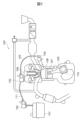
- FIG. 1 is a diagram illustrating a schematic configuration of a direct injection internal combustion engine.
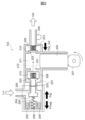
- FIG. 2 is a diagram illustrating a configuration of a high-pressure fuel pump.
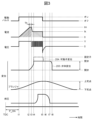
- 4 is a time chart illustrating the operation of a high-pressure fuel pump.
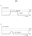
- FIG. 4A is a diagram for explaining the displacement of the valve body and the movable element when the valve is successfully closed
- FIG. 4B is a diagram for explaining the displacement of the valve body and the movable element when the valve is unsuccessfully closed.
- 5 is a diagram illustrating the relationship between the displacement of the plunger and the fuel pressure in the high-pressure pipe.
- FIG. 6 is a diagram illustrating the relationship between the peak current supply amount and the speed of a mover immediately before the valve is completely closed.
- FIG. 4 is a diagram illustrating the relationship between the valve closing completion timing and the noise level.
- FIG. 2 is a diagram for explaining the configuration of a control device for an electromagnetic actuator.
- FIG. 4 is a diagram illustrating details of a current supplied to a coil.
- 9 is a diagram for explaining specific configurations of a switching detection unit, a switching state calculation unit, and a switching state change detection unit shown in FIG. 8 .
- 11A and 11B are diagrams for explaining outputs of a differentiation circuit, a positive/negative determination circuit, a smoothing circuit, and an inflection point extraction circuit shown in FIG. 10 .
- 11 is a diagram for explaining specific configurations of a switching detection unit, a switching state calculation unit, and a switching state change detection unit according to a second embodiment.
- FIG. 13A and 13B are diagrams for explaining outputs of a conduction detection circuit, a smoothing circuit, and an inflection point extraction circuit shown in FIG. 12 .
- FIG. 1 A control device 10 for an electromagnetic actuator 200 according to the first embodiment will be described with reference to FIGS. 1 to 11.
- FIG. 1 A control device 10 for an electromagnetic actuator 200 according to the first embodiment will be described with reference to FIGS. 1 to 11.
- FIG. 1 is a diagram illustrating the general configuration of a direct injection internal combustion engine 100.
- a direct injection internal combustion engine 100 (hereinafter also referred to as "internal combustion engine 100"), fuel stored in a fuel tank 101 is pressurized to about 0.4 MPa by a feed pump 102, and is further pressurized to several tens of MPa by a high-pressure fuel pump 103.
- the pressurized fuel passes through high-pressure piping 104 and is injected from an injector 105 into a cylinder 106 of the internal combustion engine 100.
- the injected fuel is mixed with air drawn into cylinder 106 by the action of piston 107.
- This mixture is ignited by a spark generated by spark plug 108, causing an explosion.
- the heat generated by the explosion causes the mixture in cylinder 106 to expand, pushing piston 107 down.
- the force pushing piston 107 down passes through link mechanism 109 and rotates crankshaft 110.
- the rotation of crankshaft 110 is transmitted to the wheels through the transmission, providing the force that moves the vehicle.
- the main requirements for the internal combustion engine 100 are high efficiency, high power output, and low emissions, but reduced noise and vibration are also required as added value.
- the high-pressure fuel pump 103 when the valve body 203 constituting the intake valve opens and closes, noise is generated by collisions between the valve body 203 and the stopper 208, between the movable element (anchor) 204 and the stator 206, and between the valve body 203 and the seat portion 207. Automobile manufacturers and suppliers are competing to reduce this noise.
- FIG. 2 is a diagram explaining the configuration of the high-pressure fuel pump 103.
- the high-pressure fuel pump 103 is equipped with a plunger 202 that moves up and down due to the rotation of a cam 201 attached to the camshaft of the internal combustion engine 100, a valve body 203 that constitutes an intake valve that opens and closes in synchronization with the up and down movement of the plunger 202, and an electromagnetic actuator 200 that controls the opening and closing movement of the valve body 203.
- the high-pressure fuel pump 103 has a casing 223, and a pressurized chamber 211 is provided inside the casing 223. Fuel flows into the pressurized chamber 211 from the low-pressure piping 111 side through an inlet 225 and a communication port 221. The fuel that flows into the pressurized chamber 211 is discharged through an outlet 222 to the high-pressure piping 104 side.
- the outlet 222 is opened and closed by a discharge valve 210.
- the discharge valve 210 is constantly biased by a spring 226 in a direction that closes the outlet 222. When the pressure (fuel pressure) in the pressurized chamber 211 overcomes the repulsive force of the spring 226, the outlet 222 opens and discharges fuel.
- the flow of fuel into the pressurized chamber 211 is regulated by a valve body 203 that opens and closes an inlet 225.
- the opening and closing operation of the valve body 203 is controlled by an electromagnetic actuator 200.
- the electromagnetic actuator 200 is a device that converts electrical energy into mechanical energy via magnetic energy.
- the electromagnetic actuator 200 has a stator 206 that is a magnetic core, a coil 205 fixed to the stator 206, and a mover 204 that operates based on the current supplied to the coil 205.
- the movable element 204 abuts against the valve element 203 biased by the spring 215 to regulate the movement of the valve element 203, and controls the opening and closing of the valve element 203 by moving the valve element 203 in conjunction with the movement of the movable element 204.
- the movable element 204 is attracted to the stator 206 by a magnetic force generated by an electric current supplied to the coil 205, and moves the valve element 203. In other words, the movement of the movable element 204 in the axial direction (left and right direction in FIG. 2) is controlled by controlling the flow of electricity through the coil 205.
- the movable element 204 is connected to the stator 206 by a spring 209.
- the movable element 204 is constantly biased in the valve opening direction (to the right in FIG. 2) by the spring 209. As a result, the movable element 204 keeps the valve body 203 in the open position when the coil 205 is de-energized.
- a high-pressure fuel pump 103 is called a normally open type high-pressure fuel pump, and although the normally open type is described in this embodiment, it can also be applied to a normally closed type by interchangeably switching between open and closed.
- valve body 203 when the movable element 204 is attracted in the valve closing direction by the magnetic force, the valve body 203 is pushed by the spring 215 and moves in the valve closing direction. When the valve body 203 moves in the valve closing direction by the set lift amount, the valve body 203 sits on the seat portion 207 and the valve is closed. When the valve body 203 is in the valve closing state, the fuel in the pressurized chamber 211 cannot flow back to the low pressure pipe 111 side.
- Figure 3 is a time chart that explains the operation of the high-pressure fuel pump 103.
- the rotation angle of the cam 201 is detected so that the valve body 203 opens and closes in synchronization with the up and down movement of the plunger 202.
- a voltage V starts to be applied to both ends of the coil 205 (timing t1). Due to this voltage V, the current I flowing through the coil 205 increases according to Equation 1.
- LdI/dt V-RI...(Formula 1)
- L in formula 1 is the inductance of the coil 205 and the wiring
- R in formula 1 is the resistance of the coil 205 and the wiring.
- valve body 203 eventually collides with and seats on the seat portion 207. This collision blocks the fuel flow path (dotted line in Figure 2), and the fuel pressurized by the rise of the plunger 202 cannot return to the low-pressure pipe 111, causing the pressure in the pressurized chamber 211 to rise. (Timing t4)
- the discharge valve 210 opens, and the pressurized fuel is discharged into the high-pressure pipe 104 as the plunger 202 rises. After that, at timing t5, the drive pulse is turned OFF and a reverse voltage is applied to the coil 205, thereby cutting off the holding current that was being supplied to the coil 205.
- the movable element 204 moves together with the valve body 203 from the closed position to the open position (timing t7 to t8).
- the high-pressure fuel pump 103 sends fuel from the low-pressure pipe 111 to the high-pressure pipe 104.
- noise is generated when the movable element 204 collides with the stator 206 and the valve element 203 collides with the seat portion 207 to complete valve closing (timing t4 in FIG. 3), and when the valve element 203 collides with the stopper 208 to complete valve opening (timing t8 in FIG. 3).
- This noise can be unpleasant for vehicle occupants, especially when the internal combustion engine 100 is idling. Automobile manufacturers and suppliers are competing to reduce this noise.
- the aim is to reduce noise at the valve closing completion timing.
- the drive current that drives the electromagnetic actuator 200 is roughly divided into a peak current (the diagonal line portion of the current waveform in FIG. 3) and a holding current (the horizontal line portion of the current waveform in FIG. 3).
- the peak current is a current that provides energy to the movable element 204, which is held down by the spring 209 and stationary in the open valve position, to start moving the movable element 204 in order to close the valve.
- the holding current is a current that attracts the movable element 204 approaching the stator 206 until it collides with the stator 206, and maintains the operating state of the movable element 204 in contact with the stator 206 in order to maintain the valve body 203 in the closed valve position.
- valve closing completion timing Tb The timing at which the valve is closed (hereinafter also referred to as “valve closing completion timing Tb") is controlled so that it arrives during the period in which the holding current is supplied. If the amount of peak current supply is reduced, the momentum of the valve closing weakens, the speed of the valve body 203 and the movable element 204 when the valve is closed is reduced, and noise can be reduced. However, if the peak current supply amount is reduced too much, the valve will fail to close. Therefore, it is important to reduce the peak current supply amount as much as possible while still successfully closing the valve. As shown in Figure 3, the maximum current value of the peak current is Im, and the maximum current value of the holding current is Ik.
- Figure 4(a) is a diagram explaining the displacement of the valve body 203 and the movable element 204 when the valve is successfully closed.
- Figure 4(b) is a diagram explaining the displacement of the valve body 203 and the movable element 204 when the valve is unsuccessfully closed.
- Figure 5 is a diagram explaining the relationship between the displacement of the plunger 202 and the fuel pressure in the high-pressure pipe 104.
- Figure 6 is a diagram explaining the relationship between the peak current supply amount and the speed of the movable element 204 just before the valve is completely closed.
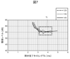
- Figure 7 is a diagram explaining the relationship between the valve closing completion timing and the noise level.
- the role of the high-pressure fuel pump 103 is to compress the fuel in the low-pressure pipe 111 and discharge it into the high-pressure pipe 104 so as to maintain the fuel pressure in the high-pressure pipe 104 at a target value.
- the high-pressure pipe 104 is provided with a fuel pressure sensor 250 that measures the fuel pressure in the high-pressure pipe 104.
- the control device 10 (see FIG. 8) of the electromagnetic actuator 200 controls the timing at which current supply to the coil 205 starts (P_ON timing) so that the measurement value of the fuel pressure sensor 250 follows the target value. If the measurement value of the fuel pressure sensor 250 is lower than the target value, the timing at which current supply to the coil 205 starts is advanced in order to increase the discharge amount. If the measurement value of the fuel pressure sensor 250 is higher than the target value, the timing at which current supply to the coil 205 starts is delayed in order to reduce the amount of fuel discharged. PID control can generally be applied to this control.
- the valve body 203 and the movable element 204 will behave as shown in FIG. 4(a) (valve closing successful). If a peak current supply amount sufficient to close the valve is not supplied to the coil 205, the valve body 203 and the movable element 204 will not be able to overcome the repulsive force of the spring 209 and will behave as shown in FIG. 4(b) (valve closing failed).
- the valve body 203 blocks the inlet 225 leading from the low pressure pipe 111 to the pressurized chamber 211, and the fuel pressure increased in the pressurized chamber 211 due to the rise of the plunger 202 is transmitted to the high pressure pipe 104.
- the fuel pressure in the high pressure pipe 104 increases in sync with the rise of the plunger 202.
- the valve is unsuccessful, even if the plunger 202 rises, the fuel in the pressurized chamber 211 escapes to the low pressure pipe 111 side. As a result, even if the plunger 202 rises, the fuel pressure in the high pressure pipe 104 does not increase, as shown by the right-downward diagonal line B in FIG. 5.
- the control device 10 of the electromagnetic actuator 200 can distinguish between successful and unsuccessful valve closing based on the measurement value of the fuel pressure sensor 250 provided in the high pressure pipe 104.
- the control device 10 increases the amount of current supplied to the coil 205 if the valve closing is unsuccessful, and decreases the amount of current supplied to the coil 205 if the valve closing is successful. In this way, by distinguishing between successful and unsuccessful valve closing based on the fuel pressure fluctuation in the high pressure pipe 104 synchronized with the up and down movement of the plunger 202, and increasing or decreasing the amount of current supply, the control device 10 can control the drive current of the electromagnetic actuator 200 near the minimum current supply amount that results in successful valve closing. This allows the control device 10 to reduce noise generated when the electromagnetic actuator 200 closes.
- valve closing failure occurs with a certain frequency.
- the peak current supply amount shown in FIG. 6 is the integral value of the drive current from timing t1 when the peak current supply starts to timing t3 when the reduction of the peak current starts in FIG. 3.
- the mover 204 When the maximum current value Im of the peak current is applied for a sufficiently long time, the mover 204 is always accelerating, but as the peak current width is shortened, the mover 204 decelerates from the point where the maximum current value Im of the peak current is terminated. It then coasts toward the stator 206 at a low speed. When the mover 204 approaches the stator 206, it is accelerated again by the electromagnetic attraction force generated by the holding current. When the mover 204 is accelerated again from a state where its speed is approximately zero by the electromagnetic attraction force of the holding current, the mover 204 moves at an approximately constant speed regardless of how it moved up to that point. This is the reason why a dead zone D exists in the relationship between the peak current supply amount and the speed vel_Tb of the mover 204 just before the valve is completely closed.
- this dead zone D Due to the existence of this dead zone D, there exists a saturation region Tr in the relationship between the level of noise generated with the closing of the valve and the valve closing completion timing Tb (the timing when the movable element 204 collides with the stator 206) in which the noise level does not decrease even if the valve closing completion timing Tb changes, as shown in FIG. 7.
- This saturation region Tr does not differ significantly even if the power supply voltage of the electromagnetic actuator 200 is different, and is a common region for various power supply voltages.
- the control device 10 of the electromagnetic actuator 200 can reduce noise associated with valve closing while suppressing valve closing failure by controlling the current to keep the valve closing completion timing Tb in the saturation region Tr. That is, when the valve closing completion timing Tb is earlier than the target timing in the saturation region Tr, the control device 10 reduces the amount of current supplied to the coil 205, and when the valve closing completion timing Tb is later than the target timing in the saturation region Tr, the control device 10 increases the amount of current supplied to the coil 205. This allows the control device 10 to control the drive current to keep the valve closing completion timing Tb in the saturation region Tr, thereby reducing noise associated with valve closing while suppressing valve closing failure.
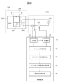
- FIG. 8 is a diagram explaining the configuration of the control device 10 of the electromagnetic actuator 200.
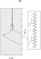
- FIG. 9 is a diagram explaining the details of the current supplied to the coil 205.
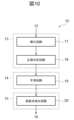
- FIG. 10 is a diagram explaining the specific configuration of the switching detection unit 13, switching state calculation unit 14, and switching state change detection unit 15 shown in FIG. 8.
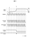
- FIG. 11 is a diagram explaining the output of the differentiation circuit 17, positive/negative determination circuit 18, smoothing circuit 19, and inflection point extraction circuit 20 shown in FIG. 10.
- Both ends of the coil 205 of the electromagnetic actuator 200 are connected to a drive circuit 300 that supplies a drive current to drive the electromagnetic actuator 200.
- the drive circuit 300 has a battery 301 that is a supply source of the current, and a switch 302 that switches whether or not the voltage of the battery 301 (power supply voltage) is applied to the coil 205. In other words, the switch 302 switches the current to the coil 205 on or off.
- the current supplying unit 11 switches the current flowing through the coil 205 to supply a switching current to the coil 205 so that the current flowing through the coil 205 is maintained within a certain range.
- the drive current of the electromagnetic actuator 200 is broadly divided into a peak current and a holding current.
- the holding current is supplied to the coil 205 as a switching current whose amplitude changes periodically within a certain range, as shown in FIG. 9, by the current supplying unit 11 switching the current flowing through the coil 205.
- the switching state change detection unit 15 may detect a change in the ratio (T1/T2) by second-order differentiation of the average value b(t) calculated by the switching state calculation unit 14.
- control device 10 of the electromagnetic actuator 200 according to the second embodiment will be described with reference to Figures 12 and 13. Descriptions of the configuration and operation of the control device 10 according to the second embodiment that are similar to those of the first embodiment will be omitted.
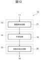
- FIG. 12 is a diagram for explaining the specific configuration of the switching detection unit 13, the switching state calculation unit 14, and the switching state change detection unit 15 of the second embodiment.
- FIG. 13 is a diagram for explaining the output of the current flow detection circuit 21, the smoothing circuit 19, and the inflection point extraction circuit 20 shown in FIG. 12.
- the control device 10 of embodiment 2 can easily detect the rise time T1 and fall time T2 of the switching current from the operation of the current-carrying unit 11, and can therefore detect the timing at which a change in the ratio (T1/T2) occurs more easily than in embodiment 1. Therefore, the control device 10 of embodiment 2 can detect the timing at which the movable element 204 operates (valve-closing completion timing Tb) more easily than in embodiment 1. Therefore, the control device 10 of embodiment 2 can accurately and easily detect the operating state of the movable element 204 of the electromagnetic actuator 200.
- the switching detection unit 13 of the second embodiment may be configured with an energization detection circuit 21 that distinguishes between an on-time when the energization unit 11 applies a voltage between the terminals of the coil 205 and an off-time when the energization unit 11 does not apply a voltage between the terminals of the coil 205, as shown in FIG. 12.
- the output of the energization detection circuit 21 is as shown in FIG. 13.
- the switching state calculation unit 14 of the second embodiment may be configured with a smoothing circuit 19 that smoothes the output of the current flow detection circuit 21, as shown in FIG. 12.
- the switching state change detection unit 15 of the second embodiment may be configured with an inflection point extraction circuit 20 that extracts an inflection point of the output of the smoothing circuit 19, as in the first embodiment.
- the outputs of the smoothing circuit 19 and the inflection point extraction circuit 20 of the second embodiment are as shown in FIG. 13, as in the first embodiment.
- the operation state detection unit 16 of the second embodiment detects the timing at which the ratio (T1/T2) detected by the switching state change detection unit 15 changes as the timing at which the movable member 204 moves, i.e., the valve closing completion timing Tb. Specifically, like the first embodiment, the operation state detection unit 16 of the second embodiment detects the timing at which the inflection point extracted by the inflection point extraction circuit 20 occurs as the valve closing completion timing Tb.
- the control device 10 of embodiment 2 can accurately detect the timing at which the movable element 204 operates (valve closing completion timing Tb) simply by combining existing circuits with simple circuit configurations. Therefore, like embodiment 1, the control device 10 of embodiment 2 can accurately and easily detect the timing at which the movable element 204 operates (valve closing completion timing Tb) without relying on the power supply voltage. Therefore, like embodiment 1, the control device 10 can accurately and easily detect the operating state of the movable element 204 of the electromagnetic actuator 200.
- the present invention is not limited to the above-described embodiments, and includes various modified examples.
- the above-described embodiments have been described in detail to clearly explain the present invention, and are not necessarily limited to those having all of the configurations described. It is also possible to replace part of the configuration of one embodiment with the configuration of another embodiment, and it is also possible to add the configuration of another embodiment to the configuration of one embodiment. It is also possible to add, delete, or replace part of the configuration of each embodiment with other configurations.
- the above-mentioned configurations, functions, processing units, processing means, etc. may be realized in part or in whole by hardware, for example by designing them as integrated circuits.
- the above-mentioned configurations, functions, etc. may also be realized by software, in which a processor interprets and executes a program that realizes each function.
- Information on the programs, tapes, files, etc. that realize each function can be stored in a memory, a recording device such as a hard disk or SSD (solid state drive), or a recording medium such as an IC card, SD card, or DVD.
- control lines and information lines shown are those considered necessary for the explanation, and do not necessarily show all control lines and information lines on the product. In reality, it can be assumed that almost all components are interconnected.
Landscapes
- Engineering & Computer Science (AREA)
- Chemical & Material Sciences (AREA)
- Combustion & Propulsion (AREA)
- Mechanical Engineering (AREA)
- General Engineering & Computer Science (AREA)
- Magnetically Actuated Valves (AREA)
Abstract
電磁アクチュエータの可動子の動作状態を正確に検知することを目的とする。制御装置10は、固定子206と、コイル205と、コイル205に供給された電流に基づき動作する可動子204とを有する電磁アクチュエータ200を制御する装置である。制御装置10は、コイル205への通電をスイッチングしてコイル205にスイッチング電流を供給する通電部11と、当該スイッチング電流の立ち上がり及び立ち下がりを検知するスイッチング検知部13と、立ち上がり時間T1と立ち下がり時間T2との比率(T1/T2)を算出するスイッチング状態算出部14と、算出された比率の変化を検知するスイッチング状態変化検知部15と、検知された比率の変化に基づいて可動子204の動作状態を検知する動作状態検知部16と、を備える。
Description
本発明は、電磁アクチュエータの制御装置に関する。
車両の内燃機関には、高効率、高出力及び低排気が求められる。これらをバランスよく解決する手段として、直噴内燃機関が普及して久しい。直噴内燃機関の重要な課題として、燃料を加圧する高圧燃料ポンプの静音化、又は、燃料を気筒内に噴射するインジェクタの噴射量の高精度化がある。
高圧燃料ポンプは、燃料の吸入量を制御する電磁アクチュエータを備えている。高圧燃料ポンプの静音化には、吸入弁を構成する弁体の閉弁時の衝突速度を低減することが必要であるが、これは閉弁のための駆動電流を低減することによって実現可能である。しかし、駆動電流を低減し過ぎると、閉弁に失敗する。閉弁に失敗しない限界の駆動電流である最小駆動電流は、弁体の開閉動作を制御する電磁アクチュエータの個体差によって高圧燃料ポンプ毎に異なる。閉弁のための最小駆動電力は、弁体を押さえつけるスプリングの力に依存する。スプリング力が強いほど、これに打ち勝って閉弁するには大きな電力を要する。一方、スプリング力が強いほど、閉弁は遅くなる。したがって、閉弁完了が遅い電磁アクチュエータは、最小駆動電力を大きく設定する必要がある。
インジェクタは、燃料の噴射量を制御する電磁アクチュエータを備えている。インジェクタの噴射量は、同じ駆動電流で駆動されても、電磁アクチュエータの個体差によってインジェクタ毎に異なる。弁体の閉弁完了タイミングと噴射量との間には相関があるので、閉弁完了タイミングを揃えるように駆動電流を制御することによって、噴射量のばらつきを低減することができる。
これらの例のように、高圧燃料ポンプの静音化、又は、インジェクタの噴射量の高精度化を実現するためには、弁体の閉弁完了タイミングを正確に検知することが必要である。閉弁完了タイミングを検知する技術として、特許文献1に開示された技術が知られている。
特許文献1には、加圧室へ燃料が流入する流入口を先端側で開閉する弁体と、前記弁体の基端側に設けられた可動子と、コイルが通電されることで前記可動子を吸引する固定子と、を備えた高圧燃料ポンプにおいて、一定の範囲で変化するとともに周波数が設定値以上、変化するタイミングが設定範囲に入る電流が前記コイルに流れる電磁アクチュエータを備えたことを特徴とする高圧燃料ポンプが開示されている。
高圧燃料ポンプ又はインジェクタに備えられた電磁アクチュエータの駆動電流は、開弁位置に静止している弁体と可動子とが動き出すエネルギを与えるピーク電流と、弁体を閉弁位置で維持するべく可動子の動作状態を維持する保持電流とに大別される。保持電流は、振幅が一定範囲で周期的に変化するスイッチング電流として電磁アクチュエータのコイルに供給される。閉弁完了タイミングは、可動子の動作状態によって規定され、保持電流が供給される期間中に到来するように制御することが、駆動電力の低減及び静音化の観点から望ましい。
特許文献1に開示された技術では、保持電流の周波数の変化を検知することによって閉弁完了タイミングを検知している。しかしながら、発明者は、保持電流の周波数が閉弁によって高くなるか低くなるかは、コイルに供給される電流の供給源であるバッテリの電圧(電源電圧)に依存することを見出した。保持電流の周波数が変化するタイミングが電源電圧によって変化してしまうので、特許文献1に開示された技術は、電源電圧に対するロバスト性を確保する点において改善の余地がある。可動子の動作状態を電源電圧に依存することなく正確に検知できることは、高圧燃料ポンプ又はインジェクタの電磁アクチュエータ以外の他の電磁アクチュエータを高精度に制御するためにも重要な課題である。
本発明は、上記に鑑みてなされたものであり、電磁アクチュエータの可動子の動作状態を正確に検知することを目的とする。
上記課題を解決するために、本発明に係る電磁アクチュエータの制御装置は、固定子と、前記固定子に固定されたコイルと、前記コイルに供給された電流に基づき動作する可動子とを有する電磁アクチュエータを制御する制御装置であって、前記コイルへの通電をスイッチングして前記コイルにスイッチング電流を供給する通電部と、前記コイルに供給された前記スイッチング電流の立ち上がり及び立ち下がりを検知するスイッチング検知部と、前記立ち上がりが検知された時間と前記立ち下がりが検知された時間との比率を算出するスイッチング状態算出部と、算出された前記比率の変化を検知するスイッチング状態変化検知部と、検知された前記比率の前記変化に基づいて前記可動子の動作状態を検知する動作状態検知部と、を備えることを特徴とする。
本発明によれば、電磁アクチュエータの可動子の動作状態を正確に検知することができる。
上記以外の課題、構成および効果は、以下の実施形態の説明により明らかにされる。
上記以外の課題、構成および効果は、以下の実施形態の説明により明らかにされる。
以下、本発明の実施形態について図面を用いて説明する。なお、各実施形態において同一の符号を付された構成又は機能については、特に言及しない限り、各実施形態において同様の構成又は機能を有し、その説明を省略する。
[実施形態1]
図1~図11を用いて、実施形態1に係る電磁アクチュエータ200の制御装置10について説明する。
図1~図11を用いて、実施形態1に係る電磁アクチュエータ200の制御装置10について説明する。
図1は、直噴内燃機関100の概略構成を説明する図である。
直噴内燃機関100(以下「内燃機関100」とも称する)では、燃料タンク101に蓄えられた燃料はフィードポンプ102において0.4MPa程度に加圧され、更に高圧燃料ポンプ103において数十MPaに加圧される。加圧された燃料は、高圧配管104を経由し、インジェクタ105から内燃機関100の気筒106に噴射される。
噴射された燃料は、ピストン107の動作により気筒106に吸入された空気と混合される。この混合気は、点火プラグ108が生成する火花によって点火され、爆発する。爆発により生成される熱により気筒106内の混合気は膨張し、ピストン107を押し下げる。ピストン107を押し下げる力はリンク機構109を経由し、クランク軸110を回転させる。クランク軸110の回転はミッションを通して車輪に伝えられ、車両を動かす力となる。
内燃機関100には、高効率、高出力及び低排気が主に求められるが、更なる付加価値として騒音及び振動の低減が求められる。高圧燃料ポンプ103においては、吸入弁を構成する弁体203の開閉の際に、弁体203とストッパ208との衝突、又は、可動子(アンカ)204と固定子206との衝突、及び、弁体203とシート部207との衝突によって騒音が発生する。自動車メーカ及びサプライヤは、この騒音の低減にしのぎを削っている。
図2は、高圧燃料ポンプ103の構成を説明する図である。
高圧燃料ポンプ103は、内燃機関100のカム軸に取り付けられたカム201の回転によって上下運動するプランジャ202と、プランジャ202の上下運動に同期して開閉動作する吸入弁を構成する弁体203と、弁体203の開閉動作を制御する電磁アクチュエータ200と、を備える。
高圧燃料ポンプ103は、ケーシング223を有し、ケーシング223の内部に加圧室211が設けられる。燃料は、低圧配管111側から、流入口225及び連通口221を通って加圧室211へ流入する。加圧室211に流入された燃料は、流出口222を通って高圧配管104側へ吐出される。流出口222は、吐出弁210によって開閉される。吐出弁210は、スプリング226によって流出口222を閉弁する方向に常時付勢されている。加圧室211の圧力(燃圧)がスプリング226の反発力に打ち勝つと、流出口222は開いて燃料を吐出する。
加圧室211への燃料の流入は、流入口225を開閉する弁体203によって規制される。弁体203の開閉動作は、電磁アクチュエータ200によって制御される。電磁アクチュエータ200は、電気エネルギを、磁気エネルギを介して機械エネルギに変換する装置である。電磁アクチュエータ200は、磁気コアである固定子206と、固定子206に固定されたコイル205と、コイル205に供給された電流に基づき動作する可動子204と、を有する。
可動子204は、スプリング215によって付勢された弁体203に当接して弁体203の動きを規制しており、可動子204の動作に連動して弁体203を動かすことによって弁体203の開閉動作を制御する。可動子204は、コイル205に供給された電流により生成された磁気力によって固定子206に吸引されて、弁体203を動かす。すなわち、コイル205の通電が制御されることによって可動子204の軸方向(図2の左右方向)の動作が制御される。
可動子204は、スプリング209によって固定子206に接続されている。可動子204は、スプリング209によって、開弁方向(図2の右方向)に常時付勢されている。これによって、可動子204は、コイル205の通電がオフの状態において、弁体203を開弁位置に保つ。このような高圧燃料ポンプ103は、ノーマルオープン型の高圧燃料ポンプと呼ばれ、本実施形態ではノーマルオープン型について説明するが、開弁と閉弁を置き換えればノーマルクローズ型にも適用できる。
コイル205の通電がオンになると、固定子206と可動子204との間に電磁吸引力が発生する。この電磁吸引力がスプリング209の反発力に打ち勝つと、弁体203の基端側に設けられる可動子204は、閉弁方向(図2の左方向)へ吸引される。可動子204が固定子206に吸引された状態において、弁体203は、弁体203の上流側及び下流側の差圧、並びに、スプリング215の反発力に基づいて開閉するチェック弁となる。したがって、可動子204が磁気力によって閉弁方向に吸引されることによって、弁体203は、スプリング215に押されて閉弁方向へ移動する。弁体203が閉弁方向へ設定されたリフト量だけ移動すると、弁体203は、シート部207に着座し、閉弁状態となる。弁体203が閉弁状態になると、加圧室211の燃料が低圧配管111側に逆流できなくなる。
図3は、高圧燃料ポンプ103の動作を説明するタイムチャートである。
弁体203がプランジャ202の上下運動に同期して開閉動作するように、カム201の回転角が検出され、例えば上死点(TDC:Top Dead Center)から決められた角度(P_ONタイミング)をカム201が回転したのちに、コイル205の両端に電圧Vが印加され始める(タイミングt1)。この電圧Vにより、コイル205に流れる電流Iは、式1に従って増加する。
LdI/dt=V-RI・・・(式1)
LdI/dt=V-RI・・・(式1)
ここで、式1のLはコイル205及び配線のインダクタンスであり、式1のRはコイル205及び配線の抵抗である。電流Iの増加に伴い固定子206が可動子204を吸引する電磁吸引力Fmagも増加する。
電磁吸引力Fmagがスプリング209の反発力Fspよりも大きくなると、反発力Fspにより押さえ付けられていた可動子204が固定子206に向かって移動し始める(タイミングt2)。可動子204が移動すると、スプリング215に押されて、弁体203も可動子204に追従して固定子206に向かい移動する。
やがて弁体203は、シート部207に衝突して着座する。この衝突により、燃料の流路(図2の点線)は塞がれ、プランジャ202の上昇により加圧された燃料は低圧配管111側に戻れなくなり、加圧室211の圧力は上昇する。(タイミングt4)
加圧室211の圧力が、吐出弁210を押さ付けるスプリング226の反発力Fsp_outよりも大きくなると、吐出弁210が開き、プランジャ202の上昇により加圧された燃料が高圧配管104に吐出される。その後、タイミングt5において、駆動パルスがOFFとなるとコイル205には逆電圧が印加され、これによりコイル205に供給されていた保持電流が遮断される。
カム角が上死点を過ぎてプランジャ202が下降し始めると(タイミングt6)、加圧室211の圧力は下がり、これがスプリング226の反発力Fsp_outよりも小さくなると、吐出弁210は閉じて、燃料の吐出は終了する。
また、加圧室211の圧力低下により、弁体203と共に可動子204が閉弁位置から開弁位置へ移動する(タイミングt7~t8)。
このような動作により、高圧燃料ポンプ103は低圧配管111から高圧配管104に燃料を送る。この過程において、可動子204が固定子206に衝突すると共に弁体203がシート部207に衝突して閉弁が完了するタイミング(図3のタイミングt4)と、弁体203がストッパ208に衝突して開弁が完了するタイミング(図3のタイミングt8)とに騒音が発生する。この騒音は、特に内燃機関100がアイドル状態の時に、車両の乗員が不快に感じることがある。自動車メーカ及びサプライヤは、この騒音の低減にしのぎを削っている。本実施形態では、閉弁完了タイミングでの騒音低減を狙っている。
電磁アクチュエータ200を駆動する駆動電流は、ピーク電流(図3の電流波形の斜線部)と、保持電流(図3の電流波形の横線部)とに大別される。ピーク電流は、スプリング209に押さえ付けられて開弁位置に静止している可動子204に対して、閉弁のために可動子204が動き出すエネルギを与える電流である。一方、保持電流は、固定子206に近付いた可動子204を、固定子206に衝突するまで引き付けて、弁体203を閉弁位置で維持するべく、可動子204の動作状態を固定子206との接触状態に維持する電流である。閉弁が完了するタイミング(以下「閉弁完了タイミングTb」とも称する)は、保持電流が供給される期間中に到来するように制御される。ピーク電流供給量を低減すれば、閉弁の勢いは弱くなり、閉弁時の弁体203及び可動子204の速度は低減され、騒音は低減できる。しかし、ピーク電流供給量を低減し過ぎると閉弁に失敗する。したがって、閉弁に成功する範囲で可能な限りピーク電流供給量を低減することが重要である。なお、図3に示すようにピーク電流の最大電流値をIm、保持電流の最大電流値をIkとする。
図4(a)は、閉弁成功時の弁体203及び可動子204の変位を説明する図である。図4(b)は、閉弁失敗時の弁体203及び可動子204の変位を説明する図である。図5は、プランジャ202の変位と高圧配管104の燃圧との関係を説明する図である。図6は、ピーク電流供給量と可動子204の閉弁完了直前の速度との関係を説明する図である。図7は、閉弁完了タイミングと騒音レベルとの関係を説明する図である。
高圧燃料ポンプ103の役割は、高圧配管104の燃圧を目標値に保つように、低圧配管111の燃料を圧縮して高圧配管104に吐出することである。このために、高圧配管104には、高圧配管104の燃圧を計測する燃圧センサ250が設けられている。電磁アクチュエータ200の制御装置10(図8を参照)は、燃圧センサ250の計測値が目標値に追従するよう、コイル205への電流供給開始タイミング(P_ONタイミング)を制御している。燃圧センサ250の計測値が目標値より低ければ、吐出量を増やすために、コイル205への電流供給開始タイミングは早くされる。燃圧センサ250の計測値が目標値より高ければ、燃料の吐出量を減らすために、コイル205への電流供給開始タイミングは遅くされる。この制御には、一般的にはPID制御が適用され得る。
前述のように、ピーク電流供給量を低減すれば、弁体203の閉弁時の速度が低減され、騒音は低減できる。しかし、ピーク電流供給量を低減し過ぎると閉弁に失敗する。すなわち、閉弁に十分なピーク電流供給量がコイル205に供給される場合には、弁体203及び可動子204は、図4(a)に示すような動作を行う(閉弁成功)。閉弁に十分なピーク電流供給量がコイル205に供給されない場合には、弁体203及び可動子204は、スプリング209の反発力に打ち勝てず、図4(b)に示すような動作を行う(閉弁失敗)。
閉弁成功の場合、弁体203は、低圧配管111から加圧室211に至る流入口225を塞ぎ、プランジャ202の上昇によって加圧室211で上昇した燃圧は、高圧配管104に伝搬する。これにより、図5の右上がり斜線部Aに示すように、プランジャ202の上昇に同期して、高圧配管104の燃圧は上昇する。一方、閉弁失敗の場合、プランジャ202が上昇しても、加圧室211の燃料は、低圧配管111側に逃げてしまう。これにより、図5の右下がり斜線部Bに示すように、プランジャ202が上昇しても、高圧配管104の燃圧は上昇しない。
電磁アクチュエータ200の制御装置10は、高圧配管104に設けられた燃圧センサ250の計測値に基づいて、閉弁成功と閉弁失敗との違いを判別することができる。制御装置10は、閉弁失敗の場合にはコイル205への電流供給量を増加させ、閉弁成功の場合にはコイル205への電流供給量を減少させる。このように、プランジャ202の上下運動に同期した高圧配管104の燃圧変動に基づいて閉弁成功及び閉弁失敗を判別し、当該電流供給量を増減させることによって、制御装置10は、電磁アクチュエータ200の駆動電流を、閉弁に成功する最小電流供給量の近傍で制御することができる。これによって、制御装置10は、電磁アクチュエータ200の閉弁に伴って発生する騒音を低減することができる。
但し、図5を用いて説明したような電磁アクチュエータ200の駆動電流を最小電流供給量の近傍で制御する場合、ある頻度で閉弁失敗が起こってしまう。発明者は、このような閉弁失敗を避けるべく、電磁アクチュエータ200の特性を調査した。その結果、発明者は、ピーク電流供給量(ピーク電流積分値II)と可動子204の閉弁完了直前の速度vel_Tbの関係には、図6に示すような、ピーク電流供給量が減少しても、閉弁完了直前の速度vel_Tbが低下しない不感帯Dが存在することを見出した。なお、図6に示すピーク電流供給量は、図3のピーク電流の供給開始のタイミングt1からピーク電流の低減が開始するタイミングt3までの駆動電流の積分値である。
ピーク電流の最大電流値Imが十分長い時間与えられる場合は、可動子204は常に加速されているが、ピーク電流幅を短くしていくと、ピーク電流の最大電流値Imを打ち切ったタイミングから可動子204は減速する。そして、低い速度で固定子206に向けて惰行する。そして、可動子204が固定子206に近付くと、保持電流によって生成される電磁吸引力によって再び加速される。速度が略ゼロの状態から保持電流による電磁吸引力によって再加速されると、可動子204は、それまでの運動の仕方に関係なく、略一定の速度で移動する。これが、ピーク電流供給量と可動子204の閉弁完了直前の速度vel_Tbとの関係に不感帯Dが存在する理由である。
この不感帯Dが存在することによって、閉弁に伴って発生する騒音のレベルと、閉弁完了タイミングTb(可動子204が固定子206に衝突するタイミング)との関係には、図7に示すように、閉弁完了タイミングTbが変化しても騒音レベルが減少しない飽和領域Trが存在する。この飽和領域Trは、電磁アクチュエータ200の電源電圧が異なっていても有意差が無く、様々な電源電圧において共通する領域となっている。
ピーク電流供給量を不感帯Dより更に低減しても、可動子204の閉弁完了直前の速度vel_Tbを不感帯Dの速度以上に低くすることはできず、むしろ閉弁に失敗する。したがって、閉弁完了タイミングTbが飽和領域Trに存在すると、閉弁失敗を抑制しつつ、閉弁に伴う騒音レベルを最小とすることができる。
このようなことから、電磁アクチュエータ200の制御装置10は、閉弁完了タイミングTbを飽和領域Trに保つよう電流を制御することによって、閉弁失敗を抑制しつつ、閉弁に伴う騒音を低減することができる。すなわち、制御装置10は、閉弁完了タイミングTbが飽和領域Trに存在する目標タイミングより早い場合には、コイル205に供給される電流の供給量を減少させ、閉弁完了タイミングTbが飽和領域Trに存在する目標タイミングより遅い場合には、コイル205に供給される電流の供給量を増加させる。これによって、制御装置10は、閉弁完了タイミングTbを飽和領域Trに保つよう駆動電流を制御することができるので、閉弁失敗を抑制しつつ、閉弁に伴う騒音を低減することができる。
閉弁完了タイミングTbを飽和領域Trに保つ制御を実現するには、閉弁完了タイミングTbを正確に検知することが必要である。そこで、以下では、図8~図11を用いて、閉弁完了タイミングTbを正確に検知可能な電磁アクチュエータ200の制御装置10について説明する。
図8は、電磁アクチュエータ200の制御装置10の構成を説明する図である。図9は、コイル205に供給される電流の詳細を説明する図である。図10は、図8に示すスイッチング検知部13、スイッチング状態算出部14及びスイッチング状態変化検知部15の具体的構成を説明する図である。図11は、図10に示す微分回路17、正負判定回路18、平滑回路19及び変曲点抽出回路20の出力を説明する図である。
電磁アクチュエータ200のコイル205の両端は、電磁アクチュエータ200を駆動する駆動電流を供給する駆動回路300に接続されている。駆動回路300は、当該電流の供給源であるバッテリ301と、コイル205に対してバッテリ301の電圧(電源電圧)を印加するか否かを切り替えるスイッチ302と、を有する。すなわち、スイッチ302は、コイル205への通電をオン又はオフに切り替える。
電磁アクチュエータ200の制御装置10は、駆動回路300のスイッチ302を制御することによって、電磁アクチュエータ200の駆動電流、すなわちコイル205に供給される電流を制御する。具体的には、制御装置10は、通電部11と、計測部12と、スイッチング検知部13と、スイッチング状態算出部14と、スイッチング状態変化検知部15と、動作状態検知部16と、を備える。
通電部11は、コイル205に流れる電流が一定範囲を維持するように、コイル205への通電をスイッチングしてコイル205にスイッチング電流を供給する。前述のように、電磁アクチュエータ200の駆動電流は、ピーク電流と、保持電流とに大別される。保持電流は、通電部11がコイル205への通電をスイッチングすることによって、図9に示すように、振幅が一定範囲で周期的に変化するスイッチング電流としてコイル205に供給される。
計測部12は、コイル205に供給されたスイッチング電流を計測し、通電部11及びスイッチング検知部13へ出力する。通電部11は、計測部12によって計測されたスイッチング電流と、予め設定されたスイッチング電流の上下限値とに基づいて、コイル205への通電をオンオフするタイミングを制御する。
スイッチング検知部13は、コイル205に供給されたスイッチング電流の立ち上がり及び立ち下がりを検知する。スイッチング電流の立ち上がりとは、コイル205への通電がオンにされることによって、図9のT1の区間のように、スイッチング電流の値が増加することである。スイッチング電流の立ち下がりとは、コイル205への通電がオフにされることによって、図9のT2区間のように、スイッチング電流の値が減少することである。
実施形態1のスイッチング検知部13は、スイッチング電流が増加したことをスイッチング電流の立ち上がりとして検知し、スイッチング電流が減少したことをスイッチング電流の立ち下がりとして検知する。
具体的には、実施形態1のスイッチング検知部13は、図10に示すように、計測部12から出力されたスイッチング電流を微分する微分回路17と、微分回路17の出力の正負を判定する正負判定回路18とによって構成されていてもよい。微分回路17は、オペアンプ、抵抗器及びコンデンサを回路構成要素とする公知のアナログ回路によって構成され得る。正負判定回路18は、オペアンプ及び抵抗器を回路構成要素とするコンパレータ回路等の公知のアナログ回路によって構成され得る。微分回路17及び正負判定回路18の各出力は、図11に示すような出力となる。
スイッチング状態算出部14は、スイッチング検知部13によってスイッチング電流の立ち上がりが検知された時間(以下「立ち上がり時間T1」とも称する)と、スイッチング電流の立ち下がりが検知された時間(以下「立ち下がり時間T2」とも称する)との比率(T1/T2)を算出する。
実施形態1のスイッチング状態算出部14は、スイッチング電流の増加が検知された時間を立ち上がり時間T1として検知し、スイッチング電流の減少が検知された時間を立ち下がり時間T2として検知する。実施形態1のスイッチング状態算出部14は、スイッチング電流の増加が検知された時間と、スイッチング電流の減少が検知された時間との比率(T1/T2)を算出する。
具体的には、実施形態1のスイッチング状態算出部14は、図10に示すように、正負判定回路18の出力を平滑化する平滑回路19によって構成されてもよい。平滑回路19は、抵抗器及びコンデンサを回路構成要素とするフィルタ回路等の公知のアナログ回路によって構成され得る。平滑回路19の出力は、図11に示すような出力となる。図11に示す平滑回路19の出力の縦軸は、比率(T1/T2)を示している。
スイッチング状態変化検知部15は、スイッチング状態算出部14によって算出された比率(T1/T2)の変化を検知する。具体的には、スイッチング状態変化検知部15は、図10に示すように、平滑回路19の出力の変曲点を抽出する変曲点抽出回路20によって構成されてもよい。変曲点抽出回路20は、2つの微分回路を直列に接続した公知のアナログ回路によって構成され得る。変曲点抽出回路20は、入力を2階微分した結果を出力する。変曲点抽出回路20の出力は、図11に示すような出力となる。
動作状態検知部16は、スイッチング状態変化検知部15によって検知された比率(T1/T2)の変化に基づいて、可動子204の動作状態を検知する。具体的には、動作状態検知部16は、検知された比率(T1/T2)の変化が生じたタイミングを、可動子204の動作が行われたタイミング、すなわち、閉弁完了タイミングTbとして検知する。より具体的には、実施形態1の動作状態検知部16は、変曲点抽出回路20が出力する比率(T1/T2)の2階微分のピークを探索し、探索されたピークが生じたタイミングを、閉弁完了タイミングTbとして検知する。探索されたピークが生じたタイミングは、変曲点抽出回路20によって抽出された変曲点が生じたタイミングを示しており、比率(T1/T2)の変化が生じたタイミングを示している。
なお、入力信号の2階微分は、当該信号のノイズを強調する特性があるが、ノイズを強調しない2階微分の方法は、
・IFAC-PapersOnLine 51(31):35-40,DOI:10.1016/j.ifacol.2018.10.007、又は、
・“Decrease of Minimum Injection Fuel Mass on The Basis of The Micro-sec-level Production Error Detection”
等の文献に記載されている。
・IFAC-PapersOnLine 51(31):35-40,DOI:10.1016/j.ifacol.2018.10.007、又は、
・“Decrease of Minimum Injection Fuel Mass on The Basis of The Micro-sec-level Production Error Detection”
等の文献に記載されている。
発明者は、閉弁完了タイミングTbを正確に検知するために、様々な電源電圧を用いてコイル205に供給されるスイッチング電流の特性を調査した。その結果は、発明者は、図9に示すように、電源電圧の違いに関わらず、閉弁完了タイミングTbの前のスイッチング電流の立ち上がり時間T1と立ち下がり時間T2との比率(T1/T2)が、閉弁完了タイミングTb後のスイッチング電流の立ち上がり時間T1と立ち下がり時間T2との比率(T1/T2)よりも大きいことを見出した。これは、閉弁完了タイミングTbの前においては、コイル205に発生する逆起電力によってスイッチング電流の立ち上がりが遅くなり、閉弁完了タイミングTbの後においては、当該逆起電力が消滅するからである。これは、電源電圧の違いに関わらず発生する事象である。これは、閉弁完了タイミングTbの前後において、スイッチング電流の立ち上がり時間T1と立ち下がり時間T2との比率(T1/T2)が変化することを意味する。したがって、制御装置10は、比率(T1/T2)の変化タイミングを検知することによって、電源電圧に依存することなく閉弁完了タイミングTbを正確に検知することができる。
以上のように、実施形態1の制御装置10は、固定子206と、固定子206に固定されたコイル205と、コイル205に供給された電流に基づき動作する可動子204とを有する電磁アクチュエータ200を制御する装置である。制御装置10は、コイル205への通電をスイッチングしてコイル205にスイッチング電流を供給する通電部11と、コイル205に供給されたスイッチング電流の立ち上がり及び立ち下がりを検知するスイッチング検知部13と、立ち上がりが検知された時間(T1)と立ち下がりが検知された時間(T2)との比率(T1/T2)を算出するスイッチング状態算出部14と、算出された比率(T1/T2)の変化を検知するスイッチング状態変化検知部15と、検知された比率(T1/T2)の変化に基づいて可動子204の動作状態を検知する動作状態検知部16と、を備える。
これにより、制御装置10は、スイッチング電流の周波数が電源電圧によって変化する場合であっても、電源電圧に依存することなく、可動子204の動作状態を正確に検知することができる。したがって、制御装置10は、電磁アクチュエータ200の可動子204の動作状態を正確に検知することができる。
更に、実施形態1の制御装置10において、スイッチング検知部13は、スイッチング電流が増加したことをスイッチング電流の立ち上がりとして検知し、スイッチング電流が減少したことをスイッチング電流の立ち下がりとして検知する。動作状態検知部16は、検知された比率(T1/T2)の変化が生じたタイミングを、可動子204の動作が行われたタイミングとして検知する。
これにより、制御装置10は、スイッチング電流の立ち上がり時間T1及び立ち下がり時間T2を確実に検知することができるので、比率(T1/T2)の変化が生じたタイミングを確実に検知することができる。したがって、制御装置10は、可動子204の動作が行われたタイミング(閉弁完了タイミングTb)を、電源電圧に依存することなく正確且つ確実に検知することができる。よって、制御装置10は、電磁アクチュエータ200の可動子204の動作状態を正確且つ確実に検知することができる。
更に、実施形態1の制御装置10において、スイッチング検知部13は、スイッチング電流を微分する微分回路17と、微分回路17の出力の正負を判定する正負判定回路18とによって構成される。スイッチング状態算出部14は、正負判定回路18の出力を平滑化する平滑回路19によって構成される。スイッチング状態変化検知部15は、平滑回路19の出力の変曲点を抽出する変曲点抽出回路20によって構成される。動作状態検知部16は、抽出された変曲点が生じたタイミングを、可動子204の動作が行われたタイミングとして検知する。
これにより、制御装置10は、回路構成が簡単な既存の回路を組み合わせるだけで、可動子204の動作が行われたタイミング(閉弁完了タイミングTb)を正確に検知することができる。したがって、制御装置10は、可動子204の動作が行われたタイミング(閉弁完了タイミングTb)を、電源電圧に依存することなく正確且つ容易に検知することができる。よって、制御装置10は、電磁アクチュエータ200の可動子204の動作状態を正確且つ容易に検知することができる。
なお、計測部12は、コイル205に供給されたスイッチング電流をサンプリングして当該スイッチング電流の計測値を取得してもよい。具体的には、計測部12は、通電部11のスイッチング周期よりも短いサンプリング周期で当該スイッチング電流をサンプリングしてもよい。計測部12は、スイッチング電流をサンプリング毎にAD変換して、スイッチング電流の計測値を取得してもよい。
スイッチング検知部13は、計測部12によって今回取得されたスイッチング電流の計測値I_(t)を、前回取得された計測値I_(t-1)と比較して、計測部12のサンプリング毎にスイッチング電流の増減判定を行い、当該増減判定の結果を示す判定値を出力してもよい。例えば、スイッチング検知部13は、今回取得されたスイッチング電流の計測値I_(t)が、前回取得された計測値I_(t-1)よりも大きい場合、スイッチング電流が増加したと判定して判定値a(t)=1を出力し、これ以外の場合、スイッチング電流が減少したと判定して判定値a(t)=-1を出力してもよい。
スイッチング状態算出部14は、スイッチング検知部13から出力された判定値a(t)を通電部11のスイッチング周期より長い所定時間に亘って平均化した平均値b(t)を算出し、算出された平均値b(t)に基づいて比率(T1/T2)を算出してもよい。平均値b(t)は、例えば、今回のサンプリングから(N-1)回遡ったサンプリングまでの各サンプリングにおいて出力された判定値a(t),a(t-1),・・・,a(t-(N-1))を平均化した値であってもよい。
スイッチング状態変化検知部15は、スイッチング状態算出部14によって算出された平均値b(t)を2階微分することによって、比率(T1/T2)の変化を検知してもよい。
これにより、制御装置10は、可動子204の動作が行われたタイミング(閉弁完了タイミングTb)を、電源電圧に依存することなくソフトウェアを用いて正確且つ容易に検知することができる。したがって、制御装置10は、電磁アクチュエータ200の可動子204の動作状態を正確且つ容易に検知することができる。
[実施形態2]
実施形態1では、スイッチング検知部13が、スイッチング電流の増減によって電流の立ち上がりと立ち下がりとを検知していたが、実施形態2では、スイッチング検知部13が、コイル205の端子間電圧から電流の立ち上がりと立ち下がりとを検知する。
実施形態1では、スイッチング検知部13が、スイッチング電流の増減によって電流の立ち上がりと立ち下がりとを検知していたが、実施形態2では、スイッチング検知部13が、コイル205の端子間電圧から電流の立ち上がりと立ち下がりとを検知する。
図12及び図13を用いて、実施形態2に係る電磁アクチュエータ200の制御装置10について説明する。実施形態2の制御装置10において、実施形態1と同様の構成及び動作については、説明を省略する。
図12は、実施形態2のスイッチング検知部13、スイッチング状態算出部14及びスイッチング状態変化検知部15の具体的構成を説明する図である。図13は、図12に示す通電検知回路21、平滑回路19及び変曲点抽出回路20の出力を説明する図である。
実施形態2のスイッチング検知部13は、コイル205の端子間に電圧が印加されたことをスイッチング電流の立ち上がりとして検知し、コイル205の端子間に電圧が印加されなかったことをスイッチング電流の立ち下がりとして検知する。実施形態2の動作状態検知部16は、実施形態1と同様に、スイッチング状態変化検知部15によって検知された比率(T1/T2)の変化が生じたタイミングを、可動子204の動作が行われたタイミング、すなわち、閉弁完了タイミングTbとして検知する。
これにより、実施形態2の制御装置10は、通電部11の動作からスイッチング電流の立ち上がり時間T1及び立ち下がり時間T2を容易に検知することができるので、比率(T1/T2)の変化が生じたタイミングを、実施形態1よりも容易に検知することができる。したがって、実施形態2の制御装置10は、可動子204の動作が行われたタイミング(閉弁完了タイミングTb)を、実施形態1よりも容易に検知することができる。よって、実施形態2の制御装置10は、電磁アクチュエータ200の可動子204の動作状態を正確且つ容易に検知することができる。
具体的には、実施形態2のスイッチング検知部13は、図12に示すように、通電部11がコイル205の端子間に電圧を印加したオン時間と、通電部11がコイル205の端子間に電圧を印加しなかったオフ時間とを判別する通電検知回路21によって構成されていてもよい。通電検知回路21の出力は、図13に示すような出力となる。
実施形態2のスイッチング状態算出部14は、図12に示すように、通電検知回路21の出力を平滑化する平滑回路19によって構成されていてもよい。実施形態2のスイッチング状態変化検知部15は、実施形態1と同様に、平滑回路19の出力の変曲点を抽出する変曲点抽出回路20によって構成されていてもよい。実施形態2の平滑回路19及び変曲点抽出回路20の各出力は、実施形態1と同様に、図13に示すような出力となる。
実施形態2の動作状態検知部16は、実施形態1と同様に、スイッチング状態変化検知部15によって検知された比率(T1/T2)の変化が生じたタイミングを、可動子204の動作が行われたタイミング、すなわち、閉弁完了タイミングTbとして検知する。具体的には、実施形態2の動作状態検知部16は、実施形態1と同様に、変曲点抽出回路20によって抽出された変曲点が生じたタイミングを、閉弁完了タイミングTbとして検知する。
これにより、実施形態2の制御装置10は、実施形態1と同様に、回路構成が簡単な既存の回路を組み合わせるだけで、可動子204の動作が行われたタイミング(閉弁完了タイミングTb)を正確に検知することができる。したがって、実施形態2の制御装置10は、実施形態1と同様に、可動子204の動作が行われたタイミング(閉弁完了タイミングTb)を、電源電圧に依存することなく正確且つ容易に検知することができる。よって、制御装置10は、実施形態1と同様に、電磁アクチュエータ200の可動子204の動作状態を正確且つ容易に検知することができる。
なお、本発明は上記の実施形態に限定されるものではなく、様々な変形例が含まれる。例えば、上記の実施形態は本発明を分かりやすく説明するために詳細に説明したものであり、必ずしも説明した全ての構成を備えるものに限定されるものではない。また、或る実施形態の構成の一部を他の実施形態の構成に置き換えることが可能であり、また、或る実施形態の構成に他の実施形態の構成を加えることも可能である。また、各実施形態の構成の一部について、他の構成の追加・削除・置換をすることが可能である。
また、上記の各構成、機能、処理部、処理手段等は、それらの一部又は全部を、例えば集積回路にて設計する等によりハードウェアによって実現してもよい。また、上記の各構成、機能等は、プロセッサがそれぞれの機能を実現するプログラムを解釈し、実行することによりソフトウェアによって実現してもよい。各機能を実現するプログラム、テープ、ファイル等の情報は、メモリや、ハードディスク、SSD(solid state drive)等の記録装置、又は、ICカード、SDカード、DVD等の記録媒体に置くことができる。
また、制御線や情報線は説明上必要と考えられるものを示しており、製品上必ずしも全ての制御線や情報線を示しているとは限らない。実際には殆ど全ての構成が相互に接続されていると考えてもよい。
10…制御装置、11…通電部、12…計測部、13…スイッチング検知部、14…スイッチング状態算出部、15…スイッチング状態変化検知部、16…動作状態検知部、17…微分回路、18…正負判定回路、19…平滑回路、20…変曲点抽出回路、21…通電検知回路、200…電磁アクチュエータ、204…可動子、205…コイル、206…固定子
Claims (6)
- 固定子と、前記固定子に固定されたコイルと、前記コイルに供給された電流に基づき動作する可動子とを有する電磁アクチュエータを制御する制御装置であって、
前記コイルへの通電をスイッチングして前記コイルにスイッチング電流を供給する通電部と、
前記コイルに供給された前記スイッチング電流の立ち上がり及び立ち下がりを検知するスイッチング検知部と、
前記立ち上がりが検知された時間と前記立ち下がりが検知された時間との比率を算出するスイッチング状態算出部と、
算出された前記比率の変化を検知するスイッチング状態変化検知部と、
検知された前記比率の前記変化に基づいて前記可動子の動作状態を検知する動作状態検知部と、を備える
ことを特徴とする電磁アクチュエータの制御装置。 - 前記スイッチング検知部は、前記スイッチング電流が増加したことを前記立ち上がりとして検知し、前記スイッチング電流が減少したことを前記立ち下がりとして検知し、
前記動作状態検知部は、検知された前記比率の前記変化が生じたタイミングを、前記可動子の動作が行われたタイミングとして検知する
ことを特徴とする請求項1に記載の電磁アクチュエータの制御装置。 - 前記スイッチング検知部は、前記コイルの端子間に電圧が印加されたことを前記立ち上がりとして検知し、前記コイルの端子間に電圧が印加されなかったことを前記立ち下がりとして検知し、
前記動作状態検知部は、検知された前記比率の前記変化が生じたタイミングを、前記可動子の動作が行われたタイミングとして検知する
ことを特徴とする請求項1に記載の電磁アクチュエータの制御装置。 - 前記スイッチング検知部は、前記スイッチング電流を微分する微分回路と、前記微分回路の出力の正負を判定する正負判定回路とによって構成され、
前記スイッチング状態算出部は、前記正負判定回路の出力を平滑化する平滑回路によって構成され、
前記スイッチング状態変化検知部は、前記平滑回路の出力の変曲点を抽出する変曲点抽出回路によって構成され、
前記動作状態検知部は、抽出された前記変曲点が生じたタイミングを、前記可動子の動作が行われたタイミングとして検知する
ことを特徴とする請求項2に記載の電磁アクチュエータの制御装置。 - 前記スイッチング検知部は、前記通電部が前記コイルの端子間に電圧を印加したオン時間と、前記通電部が前記コイルの端子間に前記電圧を印加しなかったオフ時間とを判別する通電検知回路によって構成され、
前記スイッチング状態算出部は、前記通電検知回路の出力を平滑化する平滑回路によって構成され、
前記スイッチング状態変化検知部は、前記平滑回路の出力の変曲点を抽出する変曲点抽出回路によって構成され、
前記動作状態検知部は、抽出された前記変曲点が生じたタイミングを、前記可動子の動作が行われたタイミングとして検知する
ことを特徴とする請求項3に記載の電磁アクチュエータの制御装置。 - 前記通電部のスイッチング周期よりも短いサンプリング周期で前記スイッチング電流をサンプリングして前記スイッチング電流の計測値を取得する計測部を更に備え、
前記スイッチング検知部は、今回取得された前記計測値を前回取得された前記計測値と比較して前記計測部のサンプリング毎に前記スイッチング電流の増減判定を行い、当該増減判定の結果を示す判定値を出力し、
前記スイッチング状態算出部は、出力された前記判定値を前記通電部のスイッチング周期より長い所定時間に亘って平均化した平均値を算出し、算出された平均値に基づいて前記比率を算出する
ことを特徴とする請求項2に記載の電磁アクチュエータの制御装置。
Priority Applications (3)
| Application Number | Priority Date | Filing Date | Title |
|---|---|---|---|
| PCT/JP2023/024664 WO2025009028A1 (ja) | 2023-07-03 | 2023-07-03 | 電磁アクチュエータの制御装置 |
| CN202380098997.6A CN121241196A (zh) | 2023-07-03 | 2023-07-03 | 电磁执行器的控制装置 |
| JP2025530826A JPWO2025009028A1 (ja) | 2023-07-03 | 2023-07-03 |
Applications Claiming Priority (1)
| Application Number | Priority Date | Filing Date | Title |
|---|---|---|---|
| PCT/JP2023/024664 WO2025009028A1 (ja) | 2023-07-03 | 2023-07-03 | 電磁アクチュエータの制御装置 |
Publications (1)
| Publication Number | Publication Date |
|---|---|
| WO2025009028A1 true WO2025009028A1 (ja) | 2025-01-09 |
Family
ID=94171719
Family Applications (1)
| Application Number | Title | Priority Date | Filing Date |
|---|---|---|---|
| PCT/JP2023/024664 Ceased WO2025009028A1 (ja) | 2023-07-03 | 2023-07-03 | 電磁アクチュエータの制御装置 |
Country Status (3)
| Country | Link |
|---|---|
| JP (1) | JPWO2025009028A1 (ja) |
| CN (1) | CN121241196A (ja) |
| WO (1) | WO2025009028A1 (ja) |
Citations (4)
| Publication number | Priority date | Publication date | Assignee | Title |
|---|---|---|---|---|
| JP2006250086A (ja) * | 2005-03-11 | 2006-09-21 | Hitachi Ltd | 電磁駆動機構,電磁弁機構及び電磁駆動機構によって操作される吸入弁を備えた高圧燃料供給ポンプ,電磁弁機構を備えた高圧燃料供給ポンプ |
| JP2007113462A (ja) * | 2005-10-19 | 2007-05-10 | Hitachi Ltd | 可変容量式燃料ポンプを用いた高圧燃料供給システム |
| JP2009293460A (ja) * | 2008-06-04 | 2009-12-17 | Denso Corp | 燃料供給装置 |
| JP2013194579A (ja) * | 2012-03-19 | 2013-09-30 | Denso Corp | 高圧ポンプの制御装置 |
-
2023
- 2023-07-03 JP JP2025530826A patent/JPWO2025009028A1/ja active Pending
- 2023-07-03 WO PCT/JP2023/024664 patent/WO2025009028A1/ja not_active Ceased
- 2023-07-03 CN CN202380098997.6A patent/CN121241196A/zh active Pending
Patent Citations (4)
| Publication number | Priority date | Publication date | Assignee | Title |
|---|---|---|---|---|
| JP2006250086A (ja) * | 2005-03-11 | 2006-09-21 | Hitachi Ltd | 電磁駆動機構,電磁弁機構及び電磁駆動機構によって操作される吸入弁を備えた高圧燃料供給ポンプ,電磁弁機構を備えた高圧燃料供給ポンプ |
| JP2007113462A (ja) * | 2005-10-19 | 2007-05-10 | Hitachi Ltd | 可変容量式燃料ポンプを用いた高圧燃料供給システム |
| JP2009293460A (ja) * | 2008-06-04 | 2009-12-17 | Denso Corp | 燃料供給装置 |
| JP2013194579A (ja) * | 2012-03-19 | 2013-09-30 | Denso Corp | 高圧ポンプの制御装置 |
Also Published As
| Publication number | Publication date |
|---|---|
| JPWO2025009028A1 (ja) | 2025-01-09 |
| CN121241196A (zh) | 2025-12-30 |
Similar Documents
| Publication | Publication Date | Title |
|---|---|---|
| CN107605635B (zh) | 燃料喷射装置的驱动装置 | |
| CN102272436B (zh) | 用于运行燃料喷射系统的方法 | |
| CN103635680B (zh) | 用于运行内燃机燃料输送设备的方法和装置 | |
| US11352971B2 (en) | Method of controlling a fuel injector | |
| US10557445B2 (en) | High-pressure fuel supply device for internal combustion engine | |
| CN110475959B (zh) | 燃料喷射阀的控制装置 | |
| JP6457908B2 (ja) | 制御装置及び燃料噴射システム | |
| CN1952381B (zh) | 带容量控制机构的高压燃料供给泵的控制器 | |
| WO2017022479A1 (ja) | 燃料噴射装置の制御装置 | |
| US9714632B2 (en) | Method and device for controlling a quantity control valve | |
| WO2017077877A1 (ja) | 燃料噴射装置の制御装置 | |
| CN102076953A (zh) | 用于控制高压燃料泵的方法 | |
| CN104302898B (zh) | 运行用于内燃机的燃料系统的方法及控制和/或调节机构 | |
| CN114829764B (zh) | 高压燃料泵的控制装置 | |
| US9080527B2 (en) | Method and device for controlling a quantity control valve | |
| EP3404241B1 (en) | Method to control an electromechanical linear actuator device for an internal combustion engine | |
| JP2012036886A (ja) | 高圧燃料供給ポンプの制御方法および制御装置 | |
| CN121241196A (zh) | 电磁执行器的控制装置 | |
| JP2021032178A (ja) | 電磁アクチュエータ制御装置、高圧燃料ポンプおよびインジェクタ | |
| US11236697B2 (en) | Fuel injection control device and fuel injection control method | |
| JP7814227B2 (ja) | 高圧燃料ポンプの制御装置 | |
| JP2024164443A (ja) | 内燃機関制御装置及び内燃機関制御方法 | |
| US20180291852A1 (en) | Control device for high-pressure pump |
Legal Events
| Date | Code | Title | Description |
|---|---|---|---|
| 121 | Ep: the epo has been informed by wipo that ep was designated in this application |
Ref document number: 23944280 Country of ref document: EP Kind code of ref document: A1 |
|
| ENP | Entry into the national phase |
Ref document number: 2025530826 Country of ref document: JP Kind code of ref document: A |
|
| NENP | Non-entry into the national phase |
Ref country code: DE |
|
| 122 | Ep: pct application non-entry in european phase |
Ref document number: 23944280 Country of ref document: EP Kind code of ref document: A1 |