WO2025005285A1 - 分離膜、分離膜積層体、分離モジュール又は分離塔、水素回収システム及び水素を分離・回収する方法 - Google Patents
分離膜、分離膜積層体、分離モジュール又は分離塔、水素回収システム及び水素を分離・回収する方法 Download PDFInfo
- Publication number
- WO2025005285A1 WO2025005285A1 PCT/JP2024/023643 JP2024023643W WO2025005285A1 WO 2025005285 A1 WO2025005285 A1 WO 2025005285A1 JP 2024023643 W JP2024023643 W JP 2024023643W WO 2025005285 A1 WO2025005285 A1 WO 2025005285A1
- Authority
- WO
- WIPO (PCT)
- Prior art keywords
- separation
- hydrogen
- membrane
- separation membrane
- gas
- Prior art date
- Legal status (The legal status is an assumption and is not a legal conclusion. Google has not performed a legal analysis and makes no representation as to the accuracy of the status listed.)
- Ceased
Links
Images




Classifications
-
- B—PERFORMING OPERATIONS; TRANSPORTING
- B01—PHYSICAL OR CHEMICAL PROCESSES OR APPARATUS IN GENERAL
- B01D—SEPARATION
- B01D63/00—Apparatus in general for separation processes using semi-permeable membranes
- B01D63/06—Tubular membrane modules
-
- B—PERFORMING OPERATIONS; TRANSPORTING
- B01—PHYSICAL OR CHEMICAL PROCESSES OR APPARATUS IN GENERAL
- B01D—SEPARATION
- B01D67/00—Processes specially adapted for manufacturing semi-permeable membranes for separation processes or apparatus
- B01D67/0039—Inorganic membrane manufacture
- B01D67/0051—Inorganic membrane manufacture by controlled crystallisation, e,.g. hydrothermal growth
-
- B—PERFORMING OPERATIONS; TRANSPORTING
- B01—PHYSICAL OR CHEMICAL PROCESSES OR APPARATUS IN GENERAL
- B01D—SEPARATION
- B01D67/00—Processes specially adapted for manufacturing semi-permeable membranes for separation processes or apparatus
- B01D67/0081—After-treatment of organic or inorganic membranes
- B01D67/0088—Physical treatment with compounds, e.g. swelling, coating or impregnation
-
- B—PERFORMING OPERATIONS; TRANSPORTING
- B01—PHYSICAL OR CHEMICAL PROCESSES OR APPARATUS IN GENERAL
- B01D—SEPARATION
- B01D69/00—Semi-permeable membranes for separation processes or apparatus characterised by their form, structure or properties; Manufacturing processes specially adapted therefor
- B01D69/02—Semi-permeable membranes for separation processes or apparatus characterised by their form, structure or properties; Manufacturing processes specially adapted therefor characterised by their properties
-
- B—PERFORMING OPERATIONS; TRANSPORTING
- B01—PHYSICAL OR CHEMICAL PROCESSES OR APPARATUS IN GENERAL
- B01D—SEPARATION
- B01D69/00—Semi-permeable membranes for separation processes or apparatus characterised by their form, structure or properties; Manufacturing processes specially adapted therefor
- B01D69/10—Supported membranes; Membrane supports
- B01D69/108—Inorganic support material
-
- B—PERFORMING OPERATIONS; TRANSPORTING
- B01—PHYSICAL OR CHEMICAL PROCESSES OR APPARATUS IN GENERAL
- B01D—SEPARATION
- B01D69/00—Semi-permeable membranes for separation processes or apparatus characterised by their form, structure or properties; Manufacturing processes specially adapted therefor
- B01D69/12—Composite membranes; Ultra-thin membranes
-
- B—PERFORMING OPERATIONS; TRANSPORTING
- B01—PHYSICAL OR CHEMICAL PROCESSES OR APPARATUS IN GENERAL
- B01D—SEPARATION
- B01D71/00—Semi-permeable membranes for separation processes or apparatus characterised by the material; Manufacturing processes specially adapted therefor
- B01D71/02—Inorganic material
-
- B—PERFORMING OPERATIONS; TRANSPORTING
- B01—PHYSICAL OR CHEMICAL PROCESSES OR APPARATUS IN GENERAL
- B01D—SEPARATION
- B01D71/00—Semi-permeable membranes for separation processes or apparatus characterised by the material; Manufacturing processes specially adapted therefor
- B01D71/02—Inorganic material
- B01D71/028—Molecular sieves
- B01D71/0281—Zeolites
-
- B—PERFORMING OPERATIONS; TRANSPORTING
- B01—PHYSICAL OR CHEMICAL PROCESSES OR APPARATUS IN GENERAL
- B01D—SEPARATION
- B01D71/00—Semi-permeable membranes for separation processes or apparatus characterised by the material; Manufacturing processes specially adapted therefor
- B01D71/06—Organic material
- B01D71/56—Polyamides, e.g. polyester-amides
-
- B—PERFORMING OPERATIONS; TRANSPORTING
- B01—PHYSICAL OR CHEMICAL PROCESSES OR APPARATUS IN GENERAL
- B01D—SEPARATION
- B01D71/00—Semi-permeable membranes for separation processes or apparatus characterised by the material; Manufacturing processes specially adapted therefor
- B01D71/06—Organic material
- B01D71/58—Other polymers having nitrogen in the main chain, with or without oxygen or carbon only
- B01D71/62—Polycondensates having nitrogen-containing heterocyclic rings in the main chain
- B01D71/64—Polyimides; Polyamide-imides; Polyester-imides; Polyamide acids or similar polyimide precursors
-
- C—CHEMISTRY; METALLURGY
- C01—INORGANIC CHEMISTRY
- C01B—NON-METALLIC ELEMENTS; COMPOUNDS THEREOF; METALLOIDS OR COMPOUNDS THEREOF NOT COVERED BY SUBCLASS C01C
- C01B3/00—Hydrogen; Gaseous mixtures containing hydrogen; Separation of hydrogen from mixtures containing it; Purification of hydrogen; Reversible storage of hydrogen
- C01B3/50—Separation of hydrogen or hydrogen-containing gases from gaseous mixtures, e.g. purification
- C01B3/56—Separation of hydrogen or hydrogen-containing gases from gaseous mixtures, e.g. purification by contacting with solids; Regeneration of used solids
-
- C—CHEMISTRY; METALLURGY
- C01—INORGANIC CHEMISTRY
- C01B—NON-METALLIC ELEMENTS; COMPOUNDS THEREOF; METALLOIDS OR COMPOUNDS THEREOF NOT COVERED BY SUBCLASS C01C
- C01B39/00—Compounds having molecular sieve and base-exchange properties, e.g. crystalline zeolites; Their preparation; After-treatment, e.g. ion-exchange or dealumination
- C01B39/02—Crystalline aluminosilicate zeolites; Isomorphous compounds thereof; Direct preparation thereof; Preparation thereof starting from a reaction mixture containing a crystalline zeolite of another type, or from preformed reactants; After-treatment thereof
- C01B39/36—Pentasil type, e.g. types ZSM-5, ZSM-8 or ZSM-11
- C01B39/38—Type ZSM-5
- C01B39/40—Type ZSM-5 using at least one organic template directing agent
-
- B—PERFORMING OPERATIONS; TRANSPORTING
- B01—PHYSICAL OR CHEMICAL PROCESSES OR APPARATUS IN GENERAL
- B01D—SEPARATION
- B01D2256/00—Main component in the product gas stream after treatment
- B01D2256/16—Hydrogen
-
- B—PERFORMING OPERATIONS; TRANSPORTING
- B01—PHYSICAL OR CHEMICAL PROCESSES OR APPARATUS IN GENERAL
- B01D—SEPARATION
- B01D2325/00—Details relating to properties of membranes
- B01D2325/02—Details relating to pores or porosity of the membranes
- B01D2325/0283—Pore size
- B01D2325/02831—Pore size less than 1 nm
-
- B—PERFORMING OPERATIONS; TRANSPORTING
- B01—PHYSICAL OR CHEMICAL PROCESSES OR APPARATUS IN GENERAL
- B01D—SEPARATION
- B01D2325/00—Details relating to properties of membranes
- B01D2325/20—Specific permeability or cut-off range
-
- B—PERFORMING OPERATIONS; TRANSPORTING
- B01—PHYSICAL OR CHEMICAL PROCESSES OR APPARATUS IN GENERAL
- B01D—SEPARATION
- B01D53/00—Separation of gases or vapours; Recovering vapours of volatile solvents from gases; Chemical or biological purification of waste gases, e.g. engine exhaust gases, smoke, fumes, flue gases, aerosols
- B01D53/22—Separation of gases or vapours; Recovering vapours of volatile solvents from gases; Chemical or biological purification of waste gases, e.g. engine exhaust gases, smoke, fumes, flue gases, aerosols by diffusion
- B01D53/228—Separation of gases or vapours; Recovering vapours of volatile solvents from gases; Chemical or biological purification of waste gases, e.g. engine exhaust gases, smoke, fumes, flue gases, aerosols by diffusion characterised by specific membranes
Definitions
- the present invention relates to a separation membrane that separates and recovers a desired component from a mixed gas containing multiple gas components, a separation membrane stack that includes the separation membrane, a separation module or separation tower that includes the separation membrane, a hydrogen recovery system that uses the separation membrane, and a method for separating and recovering hydrogen.
- Hydrogen is expected to be actively used as a next-generation energy source, and various methods for producing hydrogen have been proposed.
- methods proposed for producing so-called green hydrogen include electrolysis of water using renewable energy such as sunlight, and simultaneous generation of hydrogen and oxygen by total decomposition of water using photocatalysts, from which hydrogen can be separated and recovered.
- electrolysis oxygen and hydrogen are obtained from the positive and negative electrodes, but in reality, hydrogen and oxygen are mixed to a certain extent, so it is necessary to separate and recover hydrogen from this.
- hydrogen:oxygen 2:1.
- a method for separating or concentrating gases has been proposed in which a mixed gas containing multiple gas components is contacted with a separation membrane, and the more permeable component of the mixed gas is allowed to permeate, thereby separating the more permeable component from the mixed gas, or in which the less permeable component is allowed to permeate from the mixed gas (see, for example, Patent Document 1).
- a porous support-zeolite membrane composite has also been proposed as the separation membrane (see, for example, Patent Documents 2 and 3).
- a 2:1 hydrogen:oxygen mixed gas is also known as hydrogen detonation gas, and once ignited, a detonation phenomenon can occur in which a flame accompanied by a shock wave propagates at a speed exceeding the speed of sound, so sufficient safety considerations must be taken when handling it.
- the explosion range and detonation range of hydrogen-oxygen mixed gas at normal pressure are described, and a hydrogen-oxygen mixed gas having a hydrogen concentration of 3.9% by volume to 95.8% by volume is in the explosion range, and a hydrogen concentration of 15.5% by volume to 92.6% by volume is particularly considered to be in the detonation range (see Non-Patent Document 1). From the above perspective, the generated hydrogen-oxygen mixed gas needs to be safely and efficiently separated into hydrogen (or hydrogen-rich gas having an appropriate composition or higher) and oxygen (or oxygen-rich gas having an appropriate composition or higher).
- Non-Patent Document 2 describes the kinetic molecular diameters, including hydrogen 0.289 nm, oxygen 0.346 nm, carbon dioxide 0.330 nm, argon 0.34 nm, nitrogen 0.364 nm, and methane 0.38 nm. It is difficult to say that sufficient consideration has been given to separation and recovery techniques for mixed gases with such close kinetic molecular diameters.
- a specific example of the present invention is a process for separating hydrogen-oxygen mixed gas in an artificial photosynthesis plant where hydrogen-oxygen mixed gas flows.
- the artificial photosynthesis plant may include a process in which water is decomposed into hydrogen and oxygen by a photocatalyst, and then the decomposition is separated into hydrogen-rich gas and oxygen-rich gas by a gas separation membrane or the like, and the purity of the hydrogen is subsequently improved by various methods.
- the hydrogen and carbon dioxide gas can be used to produce lower olefins.
- the separation membrane used in the hydrogen-oxygen separation process can be selected from inorganic membranes mainly composed of inorganic materials, organic membranes mainly composed of organic materials, and mixed matrix membranes having a combination of these, depending on the material.
- the present invention aims to provide a separation membrane, a separation membrane stack, a separation module or separation tower, a hydrogen recovery system, and a method for separating and recovering hydrogen, which can separate and recover hydrogen safely and highly efficiently from a mixed gas consisting of molecules having relatively close dynamic molecular diameters, even when supplied at a relatively low pressure, including the separation and recovery of hydrogen from a hydrogen-oxygen mixed gas.
- Another object of the present invention is to provide a method for separating and recovering hydrogen from a mixed gas containing at least hydrogen and oxygen with high separation performance and high permeability, a separation module or separation tower for separating and recovering hydrogen with high separation performance and high permeability, and a hydrogen recovery system.
- the present inventors have found a separation membrane whose temperature dependence of permeability for multiple types of molecules constituting a mixed gas is unique compared to that of a general separation membrane.
- a separation module or separation tower equipped with the separation membrane, and further a recovery system using the separation membrane have excellent adaptability to separation and recovery of hydrogen from a mixed gas, particularly a mixed gas containing hydrogen, and have arrived at the present invention.
- the separation module or separation tower using the separation membrane of the present invention, and further a recovery system using the separation membrane can exhibit excellent separation ability even at a relatively low supply pressure.
- the present invention provides the following [1] to [27] as a first aspect of the present invention.
- the inventors have discovered that when hydrogen-oxygen mixed gas flows in an artificial photosynthesis plant or electrolysis plant and the mixed gas is separated, for example, by membrane separation, the permeability of the membrane separation and the flame-extinguishing performance for the hydrogen-oxygen mixed gas, which is necessary for safety, can be compatible within a certain temperature range, and have arrived at the present invention. That is, the present invention provides the following [28] to [56], which is a second aspect of the present invention.
- a separation membrane laminate comprising a separation membrane on a support, the separation membrane being the separation membrane according to any one of the above [1] to [5], the support being tubular, and the inner diameter ⁇ i (mm) of the support satisfying the following formula (1-VI): 6 (mm) ⁇ i (mm) ⁇ 16 (mm)...(1-VI) [7]
- a separation module or separation tower equipped with a separation membrane the separation membrane being the separation membrane according to any one of [1] to [5] above, And the temperature Tos (°C) of the separation module or separation column satisfies the following formula (1-VII): 45(°C) ⁇ Tos(°C) ⁇ 200(°C)...(1-VII) [8]
- the hydrogen recovery system according to any one of [11] to [13] above, further comprising a pressurizing mechanism for the mixed gas M supplied to the separation membrane.
- a method for separating and recovering hydrogen from a mixed gas M of hydrogen and a gas L1 having a larger kinetic molecular diameter than hydrogen, using a separation membrane comprising:
- the separation membrane is the separation membrane according to any one of [1] to [5] above, and at least one of the temperatures Tgm (°C) of the mixed gas M and the separation membrane satisfies the following formula (1-IX): 45(°C) ⁇ Tgm(°C) ⁇ 200(°C)...(1-IX) [18]
- the method for separating and recovering hydrogen according to the above [17] wherein a pressure F M (MPa(G)) of the mixed gas M supplied to the separation membrane satisfies the following formula (1-XI): 0.0 (MPa (G)) ⁇ F M (MPa (G)) ⁇ 0.2 (MPa (G))...(1-XI) [19]
- the temperature adjustment mechanism includes a tubular flow path through which a heat transfer medium flows and/or an insulating section.
- a separation membrane, a separation membrane stack, a separation module or separation tower, a hydrogen recovery system, and a method for separating and recovering hydrogen which can separate and recover hydrogen safely and highly efficiently from a mixed gas consisting of molecules having relatively close kinetic molecular diameters, even when supplied at a relatively low pressure, including the separation and recovery of hydrogen from a hydrogen-oxygen mixed gas.
- a method for separating and recovering hydrogen from a mixed gas containing at least hydrogen and oxygen with high separation performance and high permeability a separation module or separation tower for separating and recovering hydrogen, and a hydrogen recovery system.
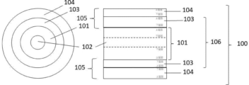
- FIG. 1 is a schematic diagram of a composite separation membrane of the present invention.
- FIG. 2 is a schematic diagram of a gas flow type device used to form a second separation section.
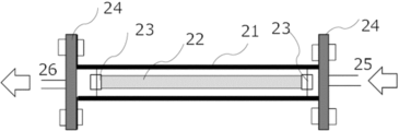
- FIG. 2 is a schematic diagram of the inside of a reaction tube of a gas flow type apparatus used to form a second separation section.
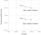
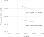
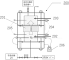
- FIG. 1 is a schematic diagram of a measurement device (or separation device) used for separating a gas mixture. 1 is an Arrhenius plot showing the activation energies of hydrogen permeance and oxygen permeance (Example 1-1).
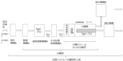
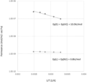
- FIG. 2 is a schematic diagram of a separation module having a heating mechanism. 1 is an Arrhenius plot showing the activation energies of hydrogen permeance and oxygen permeance (Examples 1-6).
- FIG. 1 is a schematic diagram of an experimental apparatus for determining the limit extinction pressure. 1 is a graph showing the relationship between the temperature of a hydrogen-oxygen mixed gas and the flame-extinction limit pressure based on 20° C.
- a first aspect of the present invention relates to a separation membrane, a separation membrane stack, a separation module or column, a hydrogen recovery system, and a method for separating and recovering hydrogen.
- the separation membrane of the present invention is characterized in that the activation energy Ep(S) (kJ/mol) of hydrogen permeance P(S) (mol/( m2 s Pa)) through the separation membrane, which is derived within a temperature range Tam (°C) that satisfies the following formula (1-I), and the activation energy Ep(L) (kJ/mol) of gas L (excluding hydrogen) permeance P(L) (mol/( m2 s Pa)) through the separation membrane, which is derived within the same temperature range, satisfy the following formula (1-II): 5(°C) ⁇ Tam(°C) ⁇ 200(°C)...(1-I)
- permeance is the amount of a substance permeating a separation membrane divided by the membrane area ( m2 ), time (seconds), and the partial pressure difference (Pa) between the supply side and the permeation side of the permeating substance, and its unit is [mol/( m2 ⁇ s ⁇ Pa)].
- the gas to be separated in the present invention is a mixed gas containing hydrogen, and there is no particular limitation as long as hydrogen can be suitably separated and recovered by the separation membrane, separation membrane laminate, separation module or separation tower, hydrogen recovery system, and separation and recovery method of the present invention.
- a mixed gas M containing at least hydrogen having a relatively small kinetic molecular diameter and a gas L having a relatively large kinetic molecular diameter
- any type of gas having a kinetic molecular diameter relatively larger than that of hydrogen can be selected as the gas L.
- the gas L include carbon dioxide, argon, oxygen, nitrogen, methane, etc., and it is preferable that the gas L contains at least one selected from these.
- the gas L is more preferably composed of a gas selected from carbon dioxide, argon, oxygen, nitrogen, and methane, further preferably composed of a gas selected from oxygen and nitrogen, and most preferably oxygen.
- the mixed gas may be a wet gas, but is more preferably a dry gas.
- the separation membrane of the present invention is, for example, surface-modified in order to separate gases with a dynamic molecular diameter equal to or smaller than the pore diameter with high selectivity, and is based on the discovery that there are cases in which a unique tendency is expressed in the temperature dependence of the permeability (permeance) of each gas.
- the first common example is a zeolite membrane with a widely known CHA-type framework structure.
- the pore size of this zeolite membrane is 0.38 nm, but the activation energy of the permeance of hydrogen gas with a kinetic molecular diameter of 0.289 nm is negative, and the permeation performance decreases with increasing temperature.
- the activation energy of the permeance of nitrogen gas which has a relatively large kinetic molecular diameter of 0.364 nm, also has a negative value, but the value is smaller (the absolute value is larger), and the permeability decreases more significantly when the temperature is increased.
- the relationship is established in which the temperature dependence of molecules with large kinetic molecular diameters is large (the absolute value of the activation energy is large).
- the temperature is increased to achieve high selectivity for separating and recovering hydrogen gas from a hydrogen-nitrogen mixed gas, the hydrogen gas permeability is sacrificed, resulting in a situation in which a sufficient recovery rate cannot be expected.
- the selectivity is sacrificed, resulting in a situation in which the hydrogen purity of the permeated gas does not increase.
- a silica membrane produced by the widely known CVD method is exemplified.
- the pore size depends on the production method, and usually has a distribution of pore sizes due to the amorphous structure.
- the pore size of silica is small enough to fully exhibit the molecular sieve function, and the pore size is sub-nanometer.
- the activation energy of the permeance of hydrogen gas with a kinetic molecular diameter of 0.289 nm has a positive value, and the permeability improves when the temperature is increased.
- the activation energy of the permeance of nitrogen gas with a relatively large kinetic molecular diameter of 0.364 nm also has a positive value, but the value is larger (the absolute value is also larger), and the permeability improves more when the temperature is increased. That is, even in this case, the relationship that the temperature dependence of a molecule having a large kinetic molecular diameter is large (the absolute value of the activation energy is large) holds true.
- the hydrogen gas permeability is sacrificed, resulting in a situation in which a sufficient recovery rate cannot be expected.
- the selectivity is sacrificed, resulting in a situation in which the hydrogen purity of the permeated gas does not increase.
- the absolute value of the activation energy of the permeance of the gas consisting of molecules with a large kinetic molecular diameter is greater than the absolute value of the activation energy of the permeance of hydrogen.
- the separation membrane of the present invention obtained, for example, by the process described in detail below, it is possible to separate gases having a dynamic molecular diameter equal to or smaller than the pore diameter with high selectivity. This is because the temperature dependence of the permeance of each gas exhibits a tendency not generally observed, and when this separation membrane is used in a gas separation and recovery process, it is possible to improve the performance of the entire hydrogen separation and recovery process, i.e., to achieve both high selectivity and high permeability, which is a result that could not be achieved with conventional knowledge.
- the separation membrane of the present invention is a separation membrane in which the activation energy Ep(S) (kJ/mol) of the hydrogen permeance P(S) (mol/( m2 ⁇ s ⁇ Pa)) through the separation membrane and the activation energy Ep(L) (kJ/mol) of the gas L (excluding hydrogen) permeance P(L) (mol/( m2 ⁇ s ⁇ Pa)) through the separation membrane derived within the same temperature range satisfy the relationship
- the absolute value of the activation energy of the permeance of hydrogen which has a small kinetic molecular diameter
- the absolute value of the activation energy of the permeance of gas L which has a relatively large kinetic molecular diameter, making this a "separation membrane having characteristics opposite to those of a general separation membrane.”
- the large absolute value of the activation energy means that it is highly temperature-dependent, meaning that the gas permeance, i.e., the permeation characteristics of the target gas, changes significantly whether the temperature is increased or decreased.
- two typical cases will be described as examples.
- the second case is when adsorption is considered to be the dominant factor in determining the gas permeance (gas permeability) of each gas to be separated.
- gas permeance gas permeability
- lowering the temperature improves the gas permeance of both molecules with small and large kinetic molecular diameters.
- molecules with large kinetic molecular diameters tend to be relatively more temperature-dependent, while molecules with small kinetic molecular diameters such as hydrogen tend to be relatively less temperature-dependent.
- the gas permeability improves but the gas separation performance decreases. Note that when lowering the temperature improves the gas permeance, the activation energy of the gas permeance has a negative value, so Ep(L) ⁇ Ep(S) ⁇ 0.
- the relationship between the first and second cases can be expressed as
- Depending on the combination of gases to be separated, one may be dominated by "adsorption” and the other by "diffusion,” but in these cases too, it is normal for
- the temperature can be changed to improve the permeation performance of a gas having a relatively small kinetic molecular diameter such as hydrogen, while also improving the separation performance.
- the temperature can be increased to improve both the permeation performance and the separation performance, or whether the temperature can be decreased to improve both the permeation performance and the separation performance, but in either case, it can be expressed as
- the separation membrane of the present invention preferably has a permeance of hydrogen gas having a small kinetic molecular diameter that is always greater than the permeance of gas L having a relatively large kinetic molecular diameter.
- the separation membrane of the present invention can efficiently and safely separate hydrogen from the mixed gas M. That is, it is preferable to satisfy the following formula (1-III). P(L) ⁇ P(S)...(1-III)
- the separation membrane of the present invention preferably satisfies the following formula (1-IV) in hydrogen having a relatively small kinetic molecular diameter and in gas L having a relatively large kinetic molecular diameter.
- the activation energy can be derived as follows.
- the activation energy of the permeance can be derived by setting a temperature range from 5°C to 200°C (Tam (°C) in the above formula (1-I)) as appropriate, measuring the permeance of each constituent gas in the mixed gas M to be separated at a plurality of temperatures within the temperature range, and performing a least-squares approximation using the Arrhenius equation. It is reasonable that the temperature range in which the activation energy is derived includes the temperature range in which the separation membrane of the present invention is actually used.
- the lower limit is more preferably 15° C. or more, even more preferably 20° C. or more, and particularly preferably 25° C. or more.
- the upper limit is also more preferably 140° C. or less, even more preferably 130° C. or less, and particularly preferably 120° C. or less.
- the gas may be supplied as a single gas when deriving the activation energy, or may be supplied in the form of a mixed gas for the purpose of separation and recovery.
- the former is preferable from the viewpoint of eliminating the effects of interactions between different molecules when passing through the pores in the separation membrane, while the latter is preferable from the viewpoint of constructing a separation and recovery process using a separation membrane, since it is possible to derive activation energy including interactions between different molecules that occur in the actual separation and recovery process.
- the lower limit of the gas supply pressure when deriving the activation energy must be pressurized taking into account the piping pressure loss, so it is preferably normal pressure, i.e., 0.0 MPa (G) or more, more preferably 0.005 MPa (G) or more, even more preferably 0.010 MPa (G) or more, and particularly preferably 0.015 MPa (G) or more.
- normal pressure i.e., 0.0 MPa (G) or more, more preferably 0.005 MPa (G) or more, even more preferably 0.010 MPa (G) or more, and particularly preferably 0.015 MPa (G) or more.
- the pressure on the permeation side when deriving activation energy is preferably reduced.
- the separation membrane of the present invention is suitable for use in separating and recovering hydrogen gas from a hydrogen-oxygen mixed gas (hydrogen detonation gas) with a hydrogen:oxygen ratio of 2:1.
- hydrogen-oxygen mixed gas hydrogen detonation gas
- the separation membrane of the present invention it is preferable to set the temperature range in which the activation energy described above is derived, the supply form of the gas to be separated, the supply pressure of the supplied mixed gas M, and the permeation side pressure so that the permeance of hydrogen gas, which has a small kinetic molecular diameter, is always greater than the permeance of gas L, which has a relatively large kinetic molecular diameter.
- the separation membrane of the present invention is preferably an inorganic membrane, more preferably a zeolite membrane, and particularly preferably includes a surface-modified zeolite membrane. These membranes are non-flammable and therefore highly safe, and also have high separation performance. Details will be described later.
- the separation membrane laminate of the present invention comprises a separation membrane on a support.
- the separation membrane used here is not particularly limited as long as it is the above-mentioned separation membrane of the present invention, i.e., has the above-mentioned physical properties.
- the support is preferably tubular, and the inner diameter ⁇ i (mm) satisfies the following formula (1-VI).
- a specific structure is preferably a separation membrane laminate 100 having a support 101, a first separation section 103 arranged in contact with the support, and a second separation section 104 having an amorphous structure that is not in contact with the support and is arranged in contact with the first separation section, as shown in Figure 1.
- the inside diameter may be the average diameter of a circle, but if there is no variation of 1 mm or more, the value (diameter) at the end may be used without calculating the average.
- the separation membrane laminate of the present invention can be used in a separation module or a separation column, as described below. The separation membrane laminate will be described in detail below.
- the support is not particularly limited as long as it can form the first separation part at its upper end, but it is preferable that the support is chemically stable for forming the first separation part. Furthermore, it is preferable that the support has mechanical strength in the separation process. From this viewpoint, examples of the support include ceramics, ceramic sintered bodies, metals, metal sintered bodies, various insulators, etc., and inorganic porous materials are preferable. In particular, when the first separation section is a zeolite having various structures, the support is preferably an inorganic porous material. The support may be composed of a plurality of inorganic porous materials having different pore sizes.
- the first separation section is a zeolite
- a ceramic sinter such as silica, ⁇ -alumina, ⁇ -alumina, mullite, zirconia, titania, yttria, silicon nitride, or silicon carbide is preferred.
- an inorganic porous support containing at least one of alumina, silica, and mullite is preferred. If these inorganic porous supports are used, partial zeoliteization is easy, so that the bond between the support and the zeolite is strong, and a dense membrane with high separation performance is easily formed.
- the shape of the inorganic porous support is not particularly limited as long as it can effectively separate the mixed gas M to be separated. Specific examples include flat, tubular, and cylindrical shapes.
- the upper end of the inorganic porous support is defined as the surface that forms the first separation section, and means the surface portion of the inorganic porous support where the zeolite is crystallized.
- it may be any surface of each shape, or it may be multiple surfaces.
- a cylindrical support it may be the outer surface or the inner surface, or in some cases, it may be both the outer and inner surfaces. In this case, any surface is considered to be the upper end.
- the average pore diameter of the upper end of the inorganic porous support is not particularly limited, but it is preferable that the pore diameter is controlled.
- the average pore diameter of the upper end of the inorganic porous support is usually 0.02 ⁇ m or more, preferably 0.05 ⁇ m or more, more preferably 0.1 ⁇ m or more, and usually 20 ⁇ m or less, preferably 10 ⁇ m or less, more preferably 5 ⁇ m or less.
- the average pore diameter is 0.02 ⁇ m or more, a sufficient amount of permeation is obtained, and when it is 20 ⁇ m or less, the strength of the support itself is sufficient.
- the proportion of pores at the upper end of the inorganic porous support is appropriate, and a sufficiently dense zeolite membrane is formed.
- the average pore diameter of the support from the lower end to the upper end can be changed depending on the purpose. In particular, in the upper end of the support where the first separation section is to be formed, it is preferable to make the average pore diameter smaller than that of other parts of the support in order to obtain a dense zeolite membrane.
- the average pore diameter can be determined by mercury intrusion porosimetry, gas adsorption method, or the like.
- the average thickness (wall thickness) of the inorganic porous support is usually 0.1 mm or more, preferably 0.3 mm or more, more preferably 0.5 mm or more, and usually 7 mm or less, preferably 5 mm or less, more preferably 3 mm or less.
- the inorganic porous support is used for the purpose of imparting mechanical strength to the free-isolation structure consisting of the support and the zeolite membrane (hereinafter, sometimes simply referred to as the "free-isolation structure"). If the average thickness of the inorganic porous support is 0.1 mm or more, the free-isolation structure has sufficient strength and is resistant to shocks, vibrations, etc. Furthermore, if the average thickness of the inorganic porous support is 7 mm or less, diffusion of the permeated substance is good, and sufficient permeability is obtained.
- the porosity of the inorganic porous support is usually 20% by volume or more, preferably 25% by volume or more, more preferably 30% by volume or more, and usually 70% by volume or less, preferably 60% by volume or less, more preferably 50% by volume or less.
- the porosity of the inorganic porous support affects the permeation flow rate when separating gas, and when it is 20% by volume or more, sufficient diffusion of the permeate is easily obtained. On the other hand, when it is 70% by volume or less, sufficient strength of the inorganic porous support is easily obtained.
- the porosity can be easily measured by mercury intrusion, Archimedes method, cross-sectional observation with a scanning electron microscope (SEM), etc. The porosity can also be calculated from the volume and mass using the true specific gravity.
- the upper end of the inorganic porous support may be polished with a file, etc., if necessary.
- polishing with a file, etc. for example, when there are burrs on the surface, the surface can be smoothed, and conversely, by roughening a smooth surface, the subsequent processes such as supporting the crystals and growing the crystals can be made more efficient.
- the constituent material of the first separation section is not particularly limited, and for example, an inorganic porous thin layer made of ceramics, a silica membrane, etc. can be used, but it is preferable to use a zeolite polycrystalline thin film for the first separation section. That is, it is preferable to form the first separation section by forming a zeolite polycrystalline thin film on the inorganic porous support by crystal growth.
- the components constituting the first separation section may contain, in addition to zeolite, inorganic binders such as silica and alumina, and organic compounds such as polymers as necessary, but it is preferable that the first separation section is substantially composed of zeolite alone.
- the thickness of the first separation section made of zeolite is not particularly limited, but is usually 0.1 ⁇ m or more, preferably 0.6 ⁇ m or more, more preferably 1.0 ⁇ m or more, and usually 100 ⁇ m or less, preferably 60 ⁇ m or less, more preferably 20 ⁇ m or less.
- the membrane thickness is 100 ⁇ m or less, a sufficient permeation amount is obtained, and when it is 0.1 ⁇ m or more, the selectivity of the permeating gas is good and sufficient membrane strength is obtained.
- the particle size of the zeolite is not particularly limited, but is preferably 30 nm or more, more preferably 50 nm or more, and even more preferably 100 nm or more, with the upper limit being equal to or less than the thickness of the membrane.
- the particle size of the zeolite is 30 nm or more, the grain boundary does not become large, and sufficient permeation selectivity is obtained. Therefore, it is particularly preferable that the particle size of the zeolite is the same as the thickness of the membrane.
- the grain boundary of the zeolite is the smallest.
- the zeolite membrane obtained by hydrothermal synthesis described later is particularly preferable because the particle size of the zeolite and the thickness of the membrane tend to be the same.
- This average particle size can be determined by observation with an electron microscope or by diffraction when irradiated with a laser or the like.
- the grain boundaries of zeolite crystals can be easily seen by observation under an electron microscope, and the image can be processed to remove extremely large and small particles, and the average particle size equivalent to a circle can be determined.
- the shape of the zeolite free separation structure (corresponding to 101 and 103 in FIG. 1) in which a zeolite membrane is formed on a support is not particularly limited, and any shape can be adopted, such as a tubular (cylindrical) shape, a hollow fiber shape, a monolith type, a honeycomb type, etc. Among these, a tubular (cylindrical) shape is preferred from the viewpoint of ease of separation and recovery.
- the size of the zeolite freezing structure is not particularly limited. For example, in the case of a tubular (cylindrical) structure, a length of 2 cm to 200 cm, an inner diameter of 0.05 cm to 2 cm, and a thickness of 0.5 mm to 4 mm are practical and preferred.
- the membrane length is usually 2 cm or more and 200 cm or less.
- extremely short membranes may be difficult to handle, and may cause inconveniences such as extremely small amount of gas that can be processed during actual gas separation.
- extremely long membranes may also cause inconveniences such as the need for extremely large equipment during production.
- the lower limit of the membrane length is preferably 5 cm or more, more preferably 8 cm or more, even more preferably 17.5 cm or more, and most preferably 35 cm or more.
- the upper limit of the membrane length is preferably 170 cm or less, more preferably 150 cm or less, even more preferably 130 cm or less, and most preferably 110 cm or less.
- a separation membrane having a membrane length during production of about 38 cm to 102 cm is most preferable from various viewpoints such as the size of the production apparatus, production costs, and handling.
- One of the separation functions of the zeolite liberation structure is separation as a molecular sieve, and it can suitably separate gas molecules having a size equal to or larger than the effective pore size of the zeolite used from gas molecules having a size smaller than that.
- the size of the molecules is usually about 100 ⁇ or less.
- the type of main zeolite constituting the zeolite liberation structure is not particularly limited. All zeolite structure types defined by the International Zeolite Society are included. Zeolite having a pore structure with 12 or less oxygen rings is more preferable, zeolite having a pore structure with 8 or less oxygen rings is even more preferable, and zeolite having a pore structure with 6 oxygen rings may be used. The smaller the oxygen ring, the higher the effect of narrowing the pores due to the modification reaction, and the more likely the molecular sieve effect will occur. In the present invention, zeolites having a 6-membered oxygen ring or 8-membered oxygen ring structure are particularly preferred.
- n in zeolites with n-membered oxygen rings refers to the zeolite with the largest number of oxygen atoms among the pores composed of oxygen and T elements (elements other than oxygen that compose the framework) that form the zeolite framework.
- T elements elements other than oxygen that compose the framework
- Zeolites with a pore structure containing 8 or fewer oxygen ring members include, for example, AEI, AFG, AFX, ANA, BRE, CAS, CDO, CHA, DDR, DOH, EAB, EPI, ERI, ESV, FAR, FRA, GIS, GIU, GOO, ITE, KFI, LEV, LIO, LOS, LTN, MAR, MEP, MER, MEL, MON, MSO, MTF, MTN, MWF, NON, PAU, PHI, RHO, RTE, RTH, RUT, SGT, SOD, TOL, TSC, UFI, VNI, and YUG.
- zeolites having a 6- to 8-membered oxygen ring structure examples include AEI, AFG, AFX, ANA, CHA, EAB, ERI, ESV, FAR, FRA, GIS, ITE, KFI, LEV, LIO, LOS, LTN, MAR, MWF, PAU, RHO, RTH, SOD, TOL, and UFI.
- IZA International Zeolite Association
- the n-membered oxygen ring structure determines the pore size of the zeolite, and in zeolites with oxygen rings smaller than 6-membered oxygen rings, the pore diameter is smaller than the kinetic diameter of the H 2 O molecule, so the permeability is small and the zeolite may not be practical. In addition, in zeolites with oxygen rings larger than 8-membered oxygen rings, the pore diameter is large, and the separation performance for small-sized gas components may decrease, and the applications may be limited.
- the framework density (T/1000 ⁇ ) of the zeolite is not particularly limited, but is usually 17 or less, preferably 16 or less, more preferably 15.5 or less, particularly preferably 15 or less, and is usually 10 or more, preferably 11 or more, more preferably 12 or more.
- the framework density means the number of elements (T elements) other than oxygen that constitute the framework of the zeolite per 1000 ⁇ , and this value is determined by the structure of the zeolite.
- the relationship between the framework density and the structure of the zeolite is shown in ATLAS OF ZEOLITE FRAMEWORK TYPES Fifth Revised Edition 2001 ELSEVIER.
- preferred zeolite structures are AEI, AFG, AFX, CHA, EAB, ERI, ESV, FAR, FRA, GIS, ITE, KFI, LEV, LIO, LOS, LTN, MAR, MWF, PAU, RHO, RTH, SOD, TOL, and UFI
- more preferred structures are AEI, CHA, ERI, KFI, LEV, PAU, RHO, RTH, and UFI
- even more preferred structures are CHA and LEV
- the most preferred structure is CHA.
- CHA-type zeolite refers to a zeolite with a CHA structure, a code that specifies the structure of zeolites as defined by the International Zeolite Association (IZA). This is a zeolite with a crystal structure equivalent to that of naturally occurring chabazite.
- CHA-type zeolite has a structure characterized by having three-dimensional pores consisting of eight-membered oxygen rings with a diameter of 3.8 x 3.8 ⁇ , and this structure is characterized by X-ray diffraction data.
- the framework density (T/1000 ⁇ ) of CHA-type zeolite is 14.5.
- peak intensity refers to the measured value minus the background value.
- peak intensity ratio A is usually 0.5 or more, preferably 1 or more, more preferably 1.2 or more, and particularly preferably 1.5 or more.
- the X-ray diffraction pattern referred to here is obtained by irradiating the surface on which the zeolite is mainly attached with X-rays using a CuK ⁇ radiation source, with the scanning axis set to ⁇ /2 ⁇ .
- a CuK ⁇ radiation source with the scanning axis set to ⁇ /2 ⁇ .
- the shape of the sample to be measured so long as it is a shape that allows X-rays to be irradiated onto the surface on which the zeolite of the liberation structure is mainly attached.
- the X-ray diffraction pattern may be measured by fixing the irradiation width using an automatic variable slit.
- the X-ray diffraction pattern when an automatic variable slit is used refers to a pattern in which a variable to fixed slit correction is performed.
- the peak When the peak is taken as (No. 166), it is a peak derived from the plane with indices (1,1,1) in the CHA structure.
- a peak intensity ratio B of 2 or more is considered to mean that, for example, when the CHA structure is in a rhombohedral setting, the zeolite crystals grow in an oriented manner so that the (1,0,0) plane is nearly parallel to the upper end of the freezing structure.
- Oriented growth of zeolite crystals in a zeolite freezing structure is advantageous in that it allows the production of a dense membrane with high separation performance.
- a peak intensity ratio A of 0.5 or more is considered to mean that, for example, when the CHA structure is in a rhombohedral setting, the zeolite crystals grow in an oriented manner such that the (1,1,1) plane is nearly parallel to the upper end of the liberation structure.
- the growth of zeolite crystals in an oriented manner is advantageous in that a dense membrane with high separation performance can be formed.
- the fact that either the peak intensity ratio A or B is within the above-mentioned specific range indicates that the zeolite crystals have grown in an oriented manner, and a dense membrane with high separation performance has been formed.
- the stronger the orientation the higher the separation performance tends to be, but the optimal degree of orientation for high separation performance varies depending on the mixture to be separated (gas to be separated), so it is desirable to select and use a zeolite free-form separation structure with an optimal degree of orientation depending on the mixture to be separated.
- the method for producing the liberation structure is not particularly limited as long as it is a method capable of forming the first separation portion in the support body.
- the method for producing the liberation structure is described in detail below.
- the method for producing the zeolite liberation structure is not particularly limited, but for example, a method in which zeolite is formed on an inorganic porous support by hydrothermal synthesis is preferred.
- a zeolite liberation structure can be prepared by placing a reaction mixture for hydrothermal synthesis (hereinafter, this may be referred to as an "aqueous reaction mixture"), the composition of which has been adjusted to make it uniform, into a heat-resistant and pressure-resistant vessel such as an autoclave, into which an inorganic porous support is loosely fixed, sealing the vessel, and heating the vessel for a certain period of time.
- aqueous reaction mixture a reaction mixture for hydrothermal synthesis
- the aqueous reaction mixture contains a Si element source, an Al element source, an alkali source, and water, and may further contain an organic template as necessary.
- the silicon source that can be used in the aqueous reaction mixture include amorphous silica, colloidal silica, silica gel, sodium silicate, amorphous aluminosilicate gel, tetraethoxysilane (TEOS), and trimethylethoxysilane.
- Al element source examples include sodium aluminate, aluminum hydroxide, aluminum sulfate, aluminum nitrate, aluminum oxide, amorphous aluminosilicate gel, etc.
- other element sources such as Ga, Fe, B, Ti, Zr, Sn, and Zn may be contained.
- an organic template structure-directing agent
- an organic template for synthesis By using an organic template for synthesis, the ratio of silicon atoms to aluminum atoms in the crystallized zeolite is increased, and the acid resistance and water vapor resistance are improved.
- the organic template may be of any type as long as it can form the desired zeolite liberation structure.
- one type of template may be used, or two or more types may be used in combination.
- the organic template is usually an amine or a quaternary ammonium salt.
- the organic templates described in U.S. Pat. No. 4,544,538 and U.S. Patent Publication No. 2008/0075656 are preferred.
- cations derived from alicyclic amines such as cations derived from 1-adamantanamine, cations derived from 3-quinacridinal, and cations derived from 3-exo-aminonorbornene.
- cations derived from 1-adamantanamine are more preferred.
- CHA-type zeolite capable of forming a dense membrane is crystallized. By forming a dense membrane, CHA-type zeolite with high separation performance can be obtained.
- N,N,N-trialkyl-1-adamantanammonium cations are more preferred.
- the three alkyl groups of the N,N,N-trialkyl-1-adamantanammonium cation are usually independent alkyl groups, preferably lower alkyl groups, more preferably methyl groups.
- the most preferred compound among them is the N,N,N-trimethyl-1-adamantanammonium cation.
- Such cations are accompanied by anions that are not detrimental to the formation of CHA-type zeolite.
- Representatives of such anions include halogen ions such as Cl - , Br - , and I -, hydroxide ions, sulfate ions, and carboxylate ions such as acetate ions. Of these, hydroxide ions are particularly preferred.
- N,N,N-trialkylbenzylammonium cation can also be used.
- the alkyl groups are each independently alkyl groups, preferably lower alkyl groups, more preferably methyl groups. Among them, the most preferred compound is N,N,N-trimethylbenzylammonium cation. The anion associated with this cation is the same as above.
- the alkali source used in the aqueous reaction mixture may be a hydroxide ion of the counter anion of the organic template, an alkali metal hydroxide such as NaOH or KOH, or an alkaline earth metal hydroxide such as Ca(OH) 2 .
- the type of alkali is not particularly limited, and Na, K, Li, Rb, Cs, Ca, Mg, Sr, Ba, or the like is usually used. Among these, Li, Na, and K are preferred, and K is more preferred. Two or more types of alkali may be used in combination, and specifically, Na and K, or Li and K are preferably used in combination.
- the ratio of the Si element source to the Al element source in the aqueous reaction mixture is usually expressed as the molar ratio of the oxides of each element, i.e., the SiO2 / Al2O3 molar ratio.
- the SiO2 / Al2O3 molar ratio is not particularly limited, but is usually 5 or more, preferably 8 or more, more preferably 10 or more, and even more preferably 15 or more. In addition, it is usually 10,000 or less, preferably 1,000 or less, more preferably 300 or less, and even more preferably 100 or less.
- the SiO2 / Al2O3 molar ratio is within this range, a dense zeolite liberation structure is formed, resulting in a membrane with high separation performance. Furthermore, since the formed zeolite contains an appropriate amount of Al atoms, separation performance is improved for gas components that are adsorbable to Al. Furthermore, when Al is within this range, a zeolite liberation structure with high resistance to acid and water vapor is obtained.
- the ratio of the silica source to the organic template in the aqueous reaction mixture is usually 0.005 or more, preferably 0.01 or more, more preferably 0.02 or more, and is usually 1 or less, preferably 0.4 or less, more preferably 0.2 or less.
- the ratio of the Si element source to the alkali source is, in terms of a molar ratio of M (2/n) O/ SiO2 (wherein M represents an alkali metal or an alkaline earth metal, and n represents its valence of 1 (alkali metal) or 2 (alkaline earth metal)), usually 0.02 or more, preferably 0.04 or more, more preferably 0.05 or more, and usually 0.5 or less, preferably 0.4 or less, more preferably 0.3 or less.
- the molar ratio of K to all the alkali metals and/or alkaline earth metals including K is usually 0.01 or more and 1 or less, preferably 0.1 or more and 1 or less, and more preferably 0.3 or more and 1 or less.
- the ratio of the Si element source to water in terms of the molar ratio of water to SiO2 ( H2O / SiO2 (molar ratio)), is usually 10 or more, preferably 30 or more, more preferably 40 or more, and particularly preferably 50 or more, and is usually 1,000 or less, preferably 500 or less, more preferably 200 or less, and particularly preferably 150 or less.
- the molar ratios of materials in the aqueous reaction mixture are within these ranges, dense zeolite liberation structures can be produced.
- the amount of water is particularly important in producing dense zeolite liberation structures, with conditions in which the water to silica ratio is higher than those typical of powder synthesis tend to favor denser membranes.
- the amount of water used in synthesizing powdered CHA-type zeolite is, in terms of H 2 O/SiO 2 (molar ratio), about 15 to 50.
- H 2 O/SiO 2 (molar ratio) is high (50 or more and 1000 or less), i.e., by using conditions with a high water content, it is possible to obtain a zeolite free separation structure with high separation performance in which CHA-type zeolite is crystallized in the form of a dense membrane on the inorganic porous support.
- hydrothermal synthesis it is not necessary to have seed crystals present in the reaction system, but adding seed crystals can promote the crystallization of zeolite on the inorganic porous support.
- the method of adding seed crystals is not particularly limited, and can include a method of adding seed crystals to an aqueous reaction mixture, as in the synthesis of powdered zeolite, or a method of attaching seed crystals to an inorganic porous support.
- seed crystals to the inorganic porous support By attaching seed crystals to the inorganic porous support in advance, a dense zeolite liberation structure with good separation performance is easily produced.
- the seed crystals to be used may be of any type as long as they are zeolite that promotes crystallization, but in order to efficiently crystallize, they are preferably of the same crystal type as the zeolite liberation structure to be formed.
- a CHA-type zeolite liberation structure it is preferable to use seed crystals of CHA-type zeolite.
- the particle size of the seed crystal is usually 0.5 nm or more, preferably 1 nm or more, more preferably 2 nm or more, and usually 20 ⁇ m or less, preferably 15 ⁇ m or less, more preferably 10 ⁇ m or less.
- the method for attaching the seed crystals to the inorganic porous support is not particularly limited, and examples of methods that can be used include a dipping method in which the seed crystals are dispersed in a solvent such as water and the support is immersed in the dispersion to attach the seed crystals, and a method in which the seed crystals are mixed with a solvent such as water to form a slurry, which is then applied to the inorganic porous support.
- the dipping method is desirable in order to control the amount of attached seed crystals and produce a zeolite liberation structure with good reproducibility.
- the solvent in which the seed crystals are dispersed is not particularly limited, but water is particularly preferred.
- the amount of seed crystals to be dispersed is not particularly limited, and is usually 0.01% by mass or more, preferably 0.1% by mass or more, more preferably 0.3% by mass or more, and usually 20% by mass or less, preferably 10% by mass or less, more preferably 5% by mass or less, even more preferably 4% by mass or less, and particularly preferably 3% by mass or less, based on the total mass of the dispersion.
- the amount of dispersed seed crystals is equal to or greater than the lower limit above, the amount of seed crystals adhering to the inorganic porous support is sufficient, so that zeolite is produced over the entire support during hydrothermal synthesis, leaving no areas where zeolite is not produced, resulting in a membrane without defects.
- the amount of seed crystals adhering to the inorganic porous support by the dipping method is almost constant when the amount of seed crystals in the dispersion liquid is above a certain level, so if the amount of seed crystals in the dispersion liquid is equal to or less than the upper limit above, there is no waste of seed crystals, which is advantageous in terms of cost.
- the amount of seed crystals to be attached in advance to the inorganic porous support is not particularly limited, and is usually 0.01 g or more, preferably 0.05 g or more, more preferably 0.1 g or more, and usually 100 g or less, preferably 50 g or less, more preferably 10 g or less, and even more preferably 8 g or less, in terms of mass per 1 m2 of support.
- the amount of seed crystals is equal to or greater than the lower limit, crystals are easily generated, the film grows sufficiently, and the film growth is likely to be uniform. Furthermore, when the amount of seed crystals is equal to or less than the upper limit, the seed crystals do not increase the surface unevenness, seed crystals that have fallen off the support do not facilitate the growth of spontaneous nuclei, and film growth on the support is not inhibited. Therefore, a dense zeolite free-isolation structure is easily generated.
- the zeolite liberation structure may be formed by a static method, or the zeolite liberation structure may be formed by stirring the aqueous reaction mixture.
- the temperature at which the zeolite liberation structure is formed is not particularly limited, but is usually 100° C. or higher, preferably 120° C. or higher, and more preferably 150° C. or higher, and is usually 200° C. or lower, preferably 190° C. or lower, and more preferably 180° C. or lower.
- reaction temperature is equal to or higher than the lower limit, the zeolite is likely to crystallize, whereas if the reaction temperature is equal to or lower than the upper limit, the reaction temperature is too high and a type of zeolite different from the desired zeolite is not produced.
- the heating time is not particularly limited, but is usually at least 1 hour, preferably at least 5 hours, and more preferably at least 10 hours, and is usually not more than 10 days, preferably not more than 5 days, more preferably not more than 3 days, and even more preferably not more than 2 days. If the reaction time is at least the lower limit above, the zeolite will crystallize sufficiently. On the other hand, if it is at or below the upper limit above, a type of zeolite different from the desired zeolite will not be produced.
- the pressure during the formation of the zeolite liberation structure is not particularly limited, and the autogenous pressure that occurs when an aqueous reaction mixture placed in a sealed container is heated to this temperature range is sufficient. Furthermore, an inert gas such as nitrogen may be added as necessary.
- the zeolite liberation structure obtained by hydrothermal synthesis is washed with water and then heat-treated.
- heat treatment means drying the zeolite liberation structure by applying heat, or, when a template is used, calcining and removing the template.
- the temperature is usually 50°C or higher, preferably 80°C or higher, more preferably 100°C or higher, and usually 200°C or lower, preferably 150°C or lower.
- the temperature is usually 350°C or higher, preferably 400°C or higher, more preferably 430°C or higher, even more preferably 480°C or higher, and usually 900°C or lower, preferably 850°C or lower, more preferably 800°C or lower, even more preferably 750°C or lower.
- the purpose is to remove the organic template by calcination
- the heat treatment temperature is equal to or higher than the lower limit above
- the organic template can be sufficiently removed by calcination, and no residue remains, resulting in sufficient pores in the zeolite and ensuring sufficient permeation flux during separation and concentration.
- the heat treatment temperature is equal to or lower than the upper limit above
- the difference in thermal expansion coefficient between the support and the zeolite does not become large, and cracks do not occur in the zeolite free separation structure. Therefore, sufficient density of the zeolite free separation structure can be ensured, and sufficient separation performance can be obtained.
- the heating time is not particularly limited as long as the zeolite liberation structure is sufficiently dried or the organic template is removed by firing, and is preferably 0.5 hours or more, more preferably 1 hour or more.
- the upper limit is not particularly limited, and is usually within 200 hours, preferably within 150 hours, more preferably within 100 hours.
- the heat treatment for the purpose of removing the template by firing may be performed in an air atmosphere, but may also be performed in an atmosphere containing an inert gas such as N2 or oxygen.
- the hydrothermal synthesis is carried out in the presence of an organic template, it is appropriate to wash the obtained zeolite liberated structure with water and then remove the organic template by, for example, a heat treatment or extraction, preferably by a heat treatment, i.e., calcination.
- the heating rate during the heat treatment for calcining and removing the organic template is desirably as slow as possible to reduce the occurrence of cracks in the zeolite liberation structure due to the difference in thermal expansion coefficient between the support and the zeolite.
- the heating rate is usually 5° C./min or less, preferably 2° C./min or less, more preferably 1° C./min or less, and particularly preferably 0.5° C./min or less. In consideration of workability, the heating rate is usually 0.1° C./min or more.
- the rate of temperature drop after firing must also be controlled to avoid cracks in the zeolite liberation structure. As with the rate of temperature rise, the slower the better.
- the rate of temperature drop is usually 5° C./min or less, preferably 2° C./min or less, more preferably 1° C./min or less, and particularly preferably 0.5° C./min or less. In consideration of workability, the rate is usually 0.1° C./min or more.
- the zeolite liberation structure may be ion-exchanged as necessary. When an organic template is used for synthesis, the ion-exchange is usually performed after removing the organic template.
- Ions to be ion-exchanged include protons, alkali metal ions such as Na + , K + , and Li + , Group 2 element ions such as Ca 2+ , Mg 2+ , Sr 2+ , and Ba 2+ , and transition metal ions such as Fe, Cu, and Zn.
- protons and alkali metal ions such as Na + , K + , and Li + are preferred.
- Ion exchange may be performed by treating the liberated zeolite structure after calcination (when an organic template is used, for example) with an aqueous solution containing an ammonium salt such as NH 4 NO 3 or NaNO 3 or an ion to be exchanged, or in some cases with an acid such as hydrochloric acid, usually at a temperature of room temperature to 100° C., followed by washing with water. If necessary, calcination may be performed at 200° C. to 500° C.
- the air permeation rate [L/( m2 ⁇ h)] of the zeolite liberation structure thus obtained (zeolite liberation structure after heat treatment) is usually 1400L/( m2 ⁇ h) or less, preferably 1000L/( m2 ⁇ h) or less, more preferably 700L/( m2 ⁇ h) or less, more preferably 600L/( m2 ⁇ h) or less, even more preferably 500L/( m2 ⁇ h) or less, particularly preferably 300L/( m2 ⁇ h) or less, and most preferably 200L/( m2 ⁇ h) or less.
- the lower limit of the permeation rate is not particularly limited, but is usually 0.01L/( m2 ⁇ h) or more, preferably 0.1L/( m2 ⁇ h) or more, more preferably 1L/( m2 ⁇ h) or more.
- the material of the second separation section formed at the upper end of the first separation section is not particularly limited, but it is necessary that the material exhibits a higher gas separation performance than the first separation section.
- the material in order to exhibit a high separation performance, it is preferable that the material has a smaller pore size or a higher density than the first separation section (layer).
- the main constituent elements are Si and O, and silica is particularly preferable.
- a layer with smaller pores is formed at the upper end of the liberation structure (e.g., zeolite liberation structure), so that separation performance that cannot be achieved by the function of the zeolite pore size can be easily obtained.
- the density of the amorphous layer of the composite separation membrane is preferably higher than that of the underlying zeolite.
- the ratio of the density of the amorphous layer to the density of the underlying zeolite is defined as the relative density
- a high relative density allows the separation performance of the amorphous layer to be higher than that of the zeolite, and suitable separation performance can be obtained.
- the relative density is preferably greater than 1.
- the relative density of the amorphous layer is 1.46.
- the relative density of 1.46 is considered to be the upper limit. Therefore, the relative density is 1.46 or less, preferably 1.30 or less, and more preferably 1.15 or less.
- the second separation section preferably contains Si atoms, and in particular, the Si atoms are preferably atoms supplied in a gas phase.
- the Si atoms are preferably atoms supplied in a gas phase.
- a gas phase it is advantageous in that Si can be supplied to the upper end of the first separation section with higher reactivity, and it becomes easier to more fully exhibit the desired separation performance.
- a liquid Si compound such as a silicate oligomer can be supplied using a bubbler or the like.
- the thickness of the second separation portion is the thickness from the end (lower end) of the second separation portion that contacts the first separation portion to the opposite end (upper end), and is preferably 5 nm or more and 200 nm or less. In order to exhibit practical permeability, it is preferable that the second separation part is formed to an appropriate thickness. According to the study by the present inventors, it is preferable that the second separation part is in the form of a film, and the lower limit of the film thickness is 5 nm or more, preferably 7 nm or more, more preferably 10 nm or more, and particularly preferably 12 nm or more. By making it to such a thickness, it becomes difficult to be affected by some defects and unevenness on the surface of the first separation part.
- the second separation part is thinner than a certain thickness so that the gas permeation resistance is not excessive, and the upper limit of the film thickness is 200 nm or less, preferably 100 nm or less, more preferably 50 nm or less, and most preferably 25 nm or less.
- the first separation section is made of porous ceramics or zeolite
- the second separation section is preferably one whose thickness can be adjusted, and preferably has a different type of structure with high density. For example, an amorphous structure is preferable. Also, a different type of material with high density, such as silica, is preferable.
- the second separation section is amorphous silica having the above-mentioned film thickness.
- the second separation portion is most preferably an amorphous silica film having a film thickness of 5 nm or more and 200 nm or less.
- the separation membrane laminate (composite separation membrane) of the present invention preferably has a first separation section and a second separation section, and the relative density of the second separation section to the first separation section is preferably 1.05 to 1.30.
- the relative density is 1.05 or more, high separation performance is obtained.
- the relative density is 1.30 or less, the pores are not narrowed and the permeation resistance is maintained. From the above viewpoints, it is more preferable that the relative density of the second separation section to the first separation section is 1.11 or more and 1.15 or less.
- the absolute density of the second separation section is preferably 1.58 g/cm 3 or more and 1.96 g/cm 3 or less. If the absolute density of the second separation section is 1.58 g/cm 3 or more, it is advantageous in terms of the denseness and density conditions required to exhibit separation performance. On the other hand, if the absolute density of the second separation section is 1.96 g/cm 3 or less, it is advantageous in that the permeation resistance of the permeating gas is low, and the pores are narrowed to exhibit separation performance. From the above viewpoints, it is more preferable that the absolute density of the second separation section is 1.67 g/cm 3 or more and 1.72 g/cm 3 or less.
- a free-standing separation structure is manufactured using the method described above, and a second separation section is formed on the free-standing structure by exposing the side of the first separation section opposite to the side in contact with the support (upper end) to a gas containing a molecular compound having at least Si atoms.
- a gas containing a molecular compound having at least Si atoms a gas containing a molecular compound having at least Si atoms.
- the molecular compound having Si atoms (Si compound) used in this upper end treatment for example, alkylalkoxysilanes such as methyltriethoxysilane, 3-aminopropyltriethoxysilane, 1,1,3,3-tetramethoxy-1,3-dimethylpropanedisiloxane, organosilicon compounds having siloxane such as hexamethyldisiloxane, organosilicon compounds having silazane such as hexamethyldisilazane, silicates such as tetramethoxysilane and tetraethoxysilane, silicate oligomers such as methylsilicate oligomer and ethylsilicate oligomer, colloidal silica, sodium silicate, silica sol, etc. can be used.
- alkylalkoxysilanes such as methyltriethoxysilane, 3-aminopropyltriethoxysilane
- silicate or silicate oligomer is preferred from the viewpoint of reactivity, tetraethoxysilane and methylsilicate oligomer are particularly preferred, methylsilicate oligomer is further preferred, and polymethoxysiloxane is most preferred.
- These Si compounds may be used alone or in combination of two or more.
- the method of turning the Si compound into a gaseous state may be to vaporize the Si compound from a liquid by heating, or to generate a gas by placing the Si compound liquid in a container and bubbling an inert gas for transportation such as nitrogen, helium, argon, xenon, or krypton into the liquid.
- the treatment method is not particularly limited as long as the raw material gas can be supplied to the upper end of the zeolite liberation structure and reacted. For example, there are the following two methods.
- One is a method in which the zeolite liberation structure, the Si compound liquid, and water are each sealed in a closed reactor, heated, and the gas generated by vaporization of the Si compound in the closed reactor and the water vapor generated from the water at high temperature are reacted on the upper end of the zeolite liberation structure (hereinafter, sometimes referred to as the "closed reactor method").
- the other is a method in which gas is passed through a bubbler (gas generator) containing a Si compound, and the generated Si compound gas is carried by a transport gas and supplied to a flow-type reaction tube in which a zeolite liberation structure is installed, and reacted on the upper end of the zeolite liberation structure (hereinafter, sometimes referred to as the "flow reactor method").
- a bubbler gas generator
- the generated Si compound gas is carried by a transport gas and supplied to a flow-type reaction tube in which a zeolite liberation structure is installed, and reacted on the upper end of the zeolite liberation structure
- the sealed reaction vessel method is a method in which the zeolite liberation structure, the gas generated from the Si compound, and the water vapor generated from water are allowed to coexist in a sealed reaction vessel under desired temperature conditions, and are reacted on the upper end of the zeolite liberation structure.
- the sealed reaction vessel is not particularly limited, and any vessel that can accommodate the shape and dimensions of the zeolite liberation structure may be used.
- a stainless steel autoclave with a Teflon inner tube can be used.
- a stainless steel autoclave with a Teflon inner tube is placed in a thermostatic bath at a desired temperature, the temperature and the saturated vapor pressure of the water vapor and the gas generated from the Si raw material supply source at that temperature are realized, and saturated vapor of the gas generated from the Si raw material and the water vapor is generated in the vessel.
- the water vapor and the Si raw material supply source are not limited in shape, etc., as long as they are placed in a sealed reaction vessel.
- Water and liquid Si raw material may be placed in small containers, respectively, or may be impregnated into a porous material.
- the treatment temperature is usually 20° C. or higher, preferably 60° C. or higher, more preferably 80° C. or higher, and usually 200° C. or lower, preferably 150° C. or lower, more preferably 130° C. or lower.
- the temperature is above the lower limit, the dehydration condensation reaction and hydrolysis reaction between the Si compound and the upper end of the zeolite first separation section and the Si compound proceed sufficiently, the modification treatment by the Si compound is sufficiently carried out, and the hydrophilicity of the upper end of the zeolite first separation section is sufficiently improved.
- the treatment time is usually 1 hour or more, preferably 2 hours or more, more preferably 3 hours or more, and usually 24 hours or less, preferably 8 hours or less, more preferably 5 hours or less. If the treatment time is equal to or more than the above lower limit, the reaction at the upper end of the first zeolite separation section will proceed sufficiently, and sufficient effects will be obtained. On the other hand, if the treatment time is equal to or less than the above upper limit, the reaction at the upper end of the first zeolite separation section will not proceed too far, the permeation resistance will be low, and a membrane sample with high permeation performance will be obtained.
- the gas generated from the Si compound and the steam generated from water are generated separately and supplied to a reaction tube in which a zeolite liberation structure is installed, causing a reaction at the upper end of the zeolite liberation structure.
- the gas generated from the Si compound and the steam generated from water can be supplied to the reaction tube at any time, separately or simultaneously. Therefore, the treatment can be carried out in multiple stages.
- the treatment of the upper end of the zeolite liberation structure in the reaction tube is carried out in three consecutive stages by controlling the supply gas. That is, in the first stage, only water vapor generated from water is supplied to the reaction tube using an accompanying carrier gas. In this stage, the water component is adsorbed to the upper end of the zeolite liberation structure in the reaction tube. In the second stage, both gas generated from the Si compound and water vapor generated from water are supplied to the reaction tube using a carrier gas. In this stage, the Si compound and water vapor react at the upper end of the first zeolite separation section. In the third stage, only water vapor generated from water is supplied to the reaction tube using a carrier gas. In this stage, the reaction of removing the organic groups from the Si compound proceeds.
- the shape of the reaction tube for the upper end modification process is not particularly limited. It can be any container that can accommodate the shape and dimensions of any shape of zeolite free-isolation structure, such as tubular, hollow fiber, monolithic, or honeycomb.
- the treatment time is usually 1 hour or more, preferably 2 hours or more, more preferably 3 hours or more, and usually 24 hours or less, preferably 12 hours or less, more preferably 8 hours or less. If the treatment time is equal to or greater than the lower limit, the reaction at the upper end of the first zeolite separation section will proceed sufficiently, and sufficient effects will be obtained. On the other hand, if the treatment time is equal to or less than the upper limit, the reaction at the upper end of the first zeolite separation section will not proceed too far, the permeation resistance will be low, and a membrane sample with high permeation performance will be obtained.
- the preferred composite separation membrane of the present invention is obtained by forming an amorphous silica layer by the above reaction as the second separation part.
- amorphous silica separation membranes have been reported in the past, there have been no reports of their widespread industrial use. This is because the performance of the amorphous silica separation membrane is unstable, and in particular, it is not highly stable against moisture. It is presumed that the instability of this amorphous silica separation membrane is due to the fact that the material is produced under high-temperature conditions of 300°C or higher, and the formed amorphous silica is metastable and structurally unstable, has reactive activity against moisture, and reacts with moisture after film formation, causing the amorphous silica to change in quality and its permeability to change.
- the treatment temperature is usually 20°C or higher, preferably 60°C or higher, more preferably 80°C or higher, and usually 200°C or lower, preferably 150°C or lower, more preferably 130°C or lower. Most preferably 100°C or lower. If the temperature is above the lower limit, the dehydration condensation reaction and hydrolysis reaction between the Si compound, the upper end of the zeolite first separation section, and the Si compound proceeds sufficiently, the modification process by the Si compound is carried out sufficiently, and the hydrophilicity of the upper end of the zeolite first separation section is sufficiently improved. On the other hand, if the temperature is below the upper limit, the reaction at the upper end of the zeolite first separation section does not proceed too far, the permeation resistance is low, and a membrane sample with high permeation performance is obtained.
- the flow rate of the gas (hereinafter referred to as the "supply flow rate") for bubbling or carrying the Si compound and water gas is not particularly limited, but in order to supply the amount of Si compound or water required for the reaction, it is usually 0.1 ml/min or more, preferably 1 ml/min or more, more preferably 10 ml/min or more, and even more preferably 25 ml/min or more, and the supply flow rate is usually 5000 ml/min or less, preferably 1000 ml/min or less, and more preferably 500 ml/min or less.
- the treatment of the upper end of the zeolite liberation structure can be carried out, for example, using an apparatus (flow type reactor type; raw material supply gas flow type zeolite liberation structure upper end reaction treatment apparatus) as shown in Fig. 2 as follows. That is, in Fig. 2, a container (bubbler) 1 for generating gas from a Si compound, a container (bubbler) 2 for generating steam from water, a tubular reaction tube 3, and a valve 8 are installed in a thermostatic chamber 11 by incorporating them into a piping system. A temperature control device is attached to the thermostatic chamber 11 so that the temperature of the container (bubbler), reaction tube, and gas can be adjusted.
- an apparatus flow type reactor type; raw material supply gas flow type zeolite liberation structure upper end reaction treatment apparatus
- FIG. 3 is a schematic diagram of a tubular reaction tube 21 (hereinafter, sometimes simply referred to as a "reaction tube”) incorporated as a part of a flow-type reactor system (a raw material supply gas flow-type zeolite liberation structure upper end reaction treatment device).
- reaction tube 21 a tubular reaction tube 21 (hereinafter, sometimes simply referred to as a "reaction tube") incorporated as a part of a flow-type reactor system (a raw material supply gas flow-type zeolite liberation structure upper end reaction treatment device).
- the inner diameter of the tubular reaction tube 21 is 15 mm.
- a tubular zeolite liberation structure 22 with an outer diameter of 12 mm is installed in the reaction tube and treated.
- the zeolite liberation structure 22 is fixed in the reaction tube by a zeolite membrane fixing jig 23 (hereinafter, sometimes simply referred to as a "jig").
- This jig 23 has holes or notches, so that there is no obstruction to the flow of gas. Due to this zeolite membrane fixing jig 23, the gap between the upper end of the zeolite liberation structure 22 and the inner wall of the reaction tube 21 is constant, and the supply gas for reaction flows stably.
- the reaction tube is sealed with a flange 24.
- the supply gas enters the reaction tube through the supply gas inlet pipe 25, passes through the upper end of the tubular zeolite liberation structure 22, and is exhausted through the exhaust gas pipe 26.
- the gas linear velocity and flow state at the upper end of the zeolite liberation structure 22 can be controlled.
- the procedure and convenience of supplying the raw material gas in the flow-type reactor method is explained using Figure 2.
- the porous unit-zeolite membrane composite (zeolite liberation structure) to be processed is placed in the tubular reaction tube 3, and the valve 8 of the piping is closed.
- a container (bubbler) 1 that generates a gas of the Si compound containing a liquid of the Si compound raw material and water, and a container (bubbler) 2 that generates steam from water are installed in the piping, and the valve 8 is closed.
- the temperature of the thermostatic chamber 11 is set to the desired setting value to make the temperature inside the thermostatic chamber uniform.
- the necessary valves are controlled to supply the gas containing the Si compound gas and the gas containing steam to the tubular reaction tube 3 by operating the gas flow control meter.
- the type of gas to be supplied gas containing the Si compound raw material, gas containing steam), flow rate, and time can be adjusted as desired.
- the gas supplied to the tubular reaction tube 3 passes through the steam collector 5, back pressure valve 6, and flow meter 7 and is discharged outside the device.
- the pressure inside the tubular reaction tube 3 can be adjusted by controlling the back pressure valve 6.
- separation membranes having a composite structure such as a composite separation membrane having a silica-modified part formed on various zeolite membranes other than CHA-type, a composite separation membrane having a carbon network formed on a zeolite membrane, a composite separation membrane having a carbon network formed on a silica membrane made by various CVD/sol-gel methods, and a composite separation membrane having a silica-modified part formed on a carbon membrane.
- a mixed gas containing hydrogen and oxygen is ignited, it may cause a deflagration or detonation.
- it is required to be non-flammable, have high separation performance, and be able to safely and efficiently separate and recover hydrogen, which is the target gas to be recovered.
- the separation membrane is an inorganic membrane made of an inorganic material.
- inorganic membranes zeolite membranes and silica membranes are more preferable from the viewpoint of safety than carbon membranes and the like.
- zeolite membranes which tend to have high permeance, are even more preferable, and as mentioned above, surface-modified zeolite membranes are the most preferable.
- the zeolite membrane it is most preferable for the zeolite membrane to be a zeolite membrane with a CHA-type framework structure.
- the zeolite membrane, silica membrane, and carbon membrane may be formed on a tubular support, and the lower limit of the inner diameter ⁇ i (mm) of the support is preferably 6 mm or more.
- the upper limit of the inner diameter of the support is preferably 16 mm or less.
- the inner diameter ⁇ i (mm) of the support satisfies the following formula (1-VI). 6 (mm) ⁇ i (mm) ⁇ 16 (mm)...(1-VI)
- the lower limit is more preferably 7 mm or more, and even more preferably 8 mm or more.
- the upper limit of the inner diameter is more preferably 14 mm or less, even more preferably 12 mm or less, and particularly preferably 10 mm or less, taking into consideration the mechanical strength of the tubular support.
- the feed gas may be supplied to the outside of the tubular support on which the separation active layer is formed, and hydrogen may be separated and recovered from the inside of the support, or the feed gas may be supplied to the inside of the tubular support, and hydrogen may be separated and recovered from the outside of the support on which the separation active layer is formed.
- resistance from the viewpoint of mechanical strength of the separation membrane in the event of ignition is also important.
- the inner diameter should be within the above-mentioned range.
- the tubular shape is preferable from the viewpoint of mechanical strength compared to a flat membrane configuration.
- the inner diameter may be the average diameter equivalent to a circle, and unless it changes significantly in the middle of the tube, the value (diameter) of the end may be used. More preferably, the diameter is within this range throughout the entire tube.
- the separation membrane of the present invention can be applied to a separation and recovery process by mounting it on an outer cylinder, modularizing it, and configuring it as a separation module or an even larger separation tower.
- the temperature Tos of the separation module or separation tower is 45° C. or higher and 200° C. or lower.
- the temperature range Tam for deriving the activation energy is 5° C. or higher and 200° C. or lower, but for the following reasons, the temperature of the separation module or separation tower is 45° C. or higher and 200° C. or lower. That is, the temperature Tos (°C) of the separation module or separation column satisfies the following formula (1-VII).
- a separation module or separation tower of 45 ° C or more was appropriate.
- the lower limit of the temperature range of the separation module or separation tower is 45 ° C or more, and preferably 51 ° C or more.
- the upper limit of the temperature range of the separation module or separation tower is 200 ° C or less, and preferably 150 ° C or less. That is, it is preferable to satisfy the following formula (1-VIII). 51(°C) ⁇ Tos(°C) ⁇ 150(°C)...(1-VIII)
- the lower limit is more preferably 60° C. or more, even more preferably 70° C. or more, and particularly preferably 80° C. or more.
- the upper limit is more preferably 140° C. or less, even more preferably 130° C. or less, and particularly preferably 120° C. or less.
- the separation module or separation tower of the present invention is equipped with the separation membrane of the present invention, and the temperature of the separation module or separation tower is within the temperature range in which the activation energy of the separation membrane is derived. Therefore, under any one condition selected from the temperature range of the separation module or separation tower, the supply form of the gas to be separated, the supply pressure of the gas, and the permeation side pressure, it is preferable that the permeance of hydrogen gas having a small kinetic molecular diameter is always larger than the permeance of gas L having a relatively large kinetic molecular diameter. That is, it is preferable that the following formula (1-III) is satisfied.
- the separation module or separation column of the present invention preferably satisfies the following formula (1-IV) in hydrogen having a relatively small kinetic molecular diameter and in gas L having a relatively large kinetic molecular diameter.
- the separation membrane constituting the separation module or separation tower of the present invention is preferably an inorganic membrane, more preferably a zeolite membrane, and particularly preferably includes a surface-modified zeolite membrane. These membranes are non-flammable and therefore highly safe, and also have high separation performance. Details will be described later.
- any type of gas having a kinetic molecular diameter relatively larger than that of hydrogen can be selected as the gas L.
- the gas L include carbon dioxide, argon, oxygen, nitrogen, methane, etc., and it is preferable that the gas L contains at least one selected from these.
- the gas L is more preferably composed of a gas selected from carbon dioxide, argon, oxygen, nitrogen, and methane, further preferably composed of a gas selected from oxygen and nitrogen, and most preferably oxygen.
- the mixed gas may be a wet gas, but is more preferably a dry gas.
- the separation module or separation column of the present invention can use a separation membrane laminate having a separation membrane on a support, and it is preferable that the inner diameter ⁇ i (mm) of the support satisfies the following formula (1-VI). 6 (mm) ⁇ i (mm) ⁇ 16 (mm)...(1-VI)
- the gas flow in the separation module or the separation tower is laminar.
- the viscosity of gas increases with increasing temperature, so that if other conditions are the same, the gas flow is more likely to be laminar at higher temperatures.
- using the separation membrane, separation module, or separation tower of the present invention to perform heating and separation within an appropriate temperature range not only improves both the permeability and separation performance of the separation membrane, but also has a synergistic effect of maintaining the gas flow in the separation module or the separation tower as a laminar flow, which is highly preferable.
- the lower limit of the distance between the inner wall of the separation membrane module or separation tower and the surface of the separation membrane closest to the inner wall is preferably 0.1 cm or more, more preferably 0.2 cm or more, even more preferably 0.5 cm or more, and particularly preferably 1 cm or more, in consideration of the assembly tolerance required during actual module production.
- the upper limit of the distance is preferably 50 cm or less, more preferably 25 cm or less, even more preferably 10 cm or less, and particularly preferably 2 cm or less.
- the material of the outer cylinder constituting the separation module or separation tower can be selected from any material, but from the viewpoint of use in the hydrogen-oxygen mixed gas separation and recovery process to which the present invention is suitably applied, it is preferably made of metal, and from the viewpoint of cost, it is preferably made of resin. In the former, it is particularly preferable to make the outer cylinder from stainless steel.
- the outer cylinder may be configured to enclose only the separation membrane, and in places where strong sunlight irradiation is expected, such as artificial photosynthesis plants, the outer cylinder can be installed outdoors without a special heating mechanism, and its temperature can be increased to 45° C. or higher.
- the surface color of the outer cylinder is preferably other than white, more preferably a color with a brightness of 7 or less, even more preferably a color with a brightness of 5 or less, and most preferably a color with a brightness of 3 or less. In the most preferred case, the surface color is black.
- the outer cylinder preferably has other functions as well, preferably has a dehumidifying mechanism built therein, preferably has a heating mechanism, and preferably has a flame propagation suppression function, i.e., it is preferable that the outer cylinder further has at least one of a dehumidifying mechanism, a heating mechanism, and a flame propagation suppression function.
- the dehumidifying mechanism is preferably disposed in the outer casing of the separation membrane module or separation tower on the gas supply side.
- the dehumidifying mechanism can be configured by disposing granular materials such as silica gel, zeolite, etc. on the gas supply side of the separation module or separation tower.
- granular materials such as silica gel, zeolite, etc.
- a part of the gas supply side of a zeolite membrane on a tubular alumina support can function as the dehumidifying mechanism.
- granular materials such as silica gel, zeolite, etc. are disposed on the gas supply side of the separation module or separation tower, it is also possible to have them simultaneously assume part or all of the flame propagation suppression function by appropriately controlling the particle size.
- the heating mechanism may be, for example, a flow path for circulating a heat medium that is installed so as to be in contact with the outer wall surface of the outer cylinder of the separation module or separation tower, a mechanism for efficiently applying hot air to the outer wall surface of the outer cylinder, or a heating element that is directly wrapped around the outer wall surface of the outer cylinder.
- a mechanism for heating/cooling water may be provided in a location separate from the separation module or separation tower to adjust the temperature.
- the separation membrane of the present invention can simultaneously achieve higher separation performance and higher permeability.
- the dehumidification mechanism and the heating mechanism have the combined function of lowering the relative humidity of the mixed gas immediately before it is supplied to the separation membrane. This is because it is possible to lower the relative humidity in two stages by first removing some of the water vapor from the mixed gas supplied by the dehumidification mechanism, and then raising the temperature by the heating mechanism.
- the flame propagation suppression mechanism can be particularly suitably used when separating and recovering hydrogen from a hydrogen-oxygen mixed gas or the like using a separation module or separation tower equipped with the separation membrane of the present invention.
- the flame propagation suppression mechanism can be installed in the outer cylinder of the separation module or separation tower at any location selected from the gas supply side, the gas permeation side, and the gas non-permeation side.
- the gas supply side is the site where the mixed gas before separation flows, and therefore the risk of ignition is the highest. Therefore, it is preferable to provide a flame propagation suppression mechanism on the gas supply side.
- the non-permeation side is a hydrogen-oxygen mixed gas with a reduced hydrogen concentration or an increased oxygen concentration.
- the permeation side will be a hydrogen-oxygen mixed gas with an increased hydrogen concentration or a decreased oxygen concentration.
- the permeation side will also usually be a hydrogen-oxygen mixed gas. Therefore, it is preferable to provide a flame propagation suppression mechanism on the permeation side.
- the flame propagation suppression mechanism can be made of a narrow passage (a passage narrower than other parts), a sintered metal body, a mesh structure, etc. The former may be filled with explosion-resistant granules.
- the sintered metal body, etc. is preferably made of stainless steel.
- the hydrogen recovery system of the present invention is a hydrogen recovery system equipped with a separation membrane, in which the activation energy Ep(S) (kJ/mol) of hydrogen permeance P(S) (mol/( m2 s Pa)) through the separation membrane and the activation energy Ep(L) (kJ/mol) of gas L permeance P(L) (mol/( m2 s Pa)) through the separation membrane satisfy the following formula (1-II):
- at least one of the temperatures Tgm (° C.) of the mixed gas M to be separated and recovered in the recovery system and the temperature of the separation membrane satisfies the following formula (1-IX).
- the separation membrane in the hydrogen recovery system of the present invention is preferably an inorganic membrane, more preferably a zeolite membrane, and particularly preferably includes a surface-modified zeolite membrane. These membranes are non-flammable and therefore highly safe, and also have high separation performance.
- the mixed gas preferably contains at least one gas selected from carbon dioxide, argon, oxygen, nitrogen, and methane, and more preferably is composed of a gas selected from carbon dioxide, argon, oxygen, nitrogen, and methane in addition to the hydrogen to be recovered. It is further preferable that the mixed gas is composed of a gas selected from oxygen and nitrogen in addition to the hydrogen to be recovered. It is most preferable that the mixed gas is composed of oxygen in addition to the hydrogen to be recovered.
- the mixed gas may be a wet gas, but is more preferably a dry gas.
- the temperature Tgm of at least one of the mixed gas, the separation module, or the separation tower is preferably 45° C. or higher and 200° C. or lower.
- the temperature range Tam for deriving the activation energy is 5° C. or higher and 200° C. or lower, but for the following reasons, the temperature of at least one of the mixed gas, the separation module, or the separation tower is 45° C. or higher and 200° C. or lower, and it is preferable that all temperatures are 45° C. or higher and 200° C. or lower. That is, it is preferable to satisfy the following formula (1-IX). 45(°C) ⁇ Tgm(°C) ⁇ 200(°C)...(1-IX)
- a separation module or separation tower of 45 ° C or more was appropriate in the study by the present inventors. However, in addition to this, it was effective to preheat the temperature of the mixed gas to be separated in the same manner as the separation module or separation tower.
- the lower limit of the temperature range of at least one of the mixed gas, separation module, or separation tower is 45 ° C or more, preferably 51 ° C or more, more preferably 60 ° C or more, even more preferably 70 ° C or more, and most preferably 80 ° C or more.
- the upper limit of the temperature range of at least one of the mixed gas, the separation module, or the separation column is 200°C or less, preferably 150°C or less, more preferably 140°C or less, even more preferably 130°C or less, and most preferably 120°C or less.
- the most preferable and effective method for separating the mixed gas to be separated is to preheat the gas mixture and also heat the outer casing of the separation module, thereby performing heated separation.
- water used as the heat medium in the heating mechanism
- the hydrogen recovery system of the present invention may be configured as shown in FIG. 4, for example, and is equipped with the separation membrane of the present invention, and the temperature of the gas to be separated, the separation module or the separation tower is within the temperature range in which the activation energy of the separation membrane is derived. Therefore, under any condition selected from the temperature range of the gas to be separated, the temperature range of the separation module or the separation tower, the supply form of the gas to be separated, the supply pressure of the gas, and the permeation side pressure, it is preferable that the permeance of hydrogen gas with a small kinetic molecular diameter is always greater than the permeance of gas L with a relatively large kinetic molecular diameter.
- the hydrogen recovery system of the present invention preferably has a mechanism for adjusting the pressure of the mixed gas supplied to the separation membrane, separation membrane module, or separation column according to the purpose.
- a pressurizing mechanism it is preferable to have a pressurizing mechanism for the mixed gas M supplied to the separation module or separation tower.
- the pressurizing mechanism it is preferable to install a boost pump upstream of the separation membrane, separation membrane module, or separation tower (pressurizing mechanism A), and it is also preferable to install an exhaust valve on the non-permeation side of the separation membrane, separation membrane module, or separation tower (pressurizing mechanism B).
- a boost pump it is preferable to boost the mixed gas, since it is possible to improve the supply pressure of the gas to be separated without increasing the pressure on the photocatalyst panel side, and the separation and recovery efficiency as a process is also improved.
- the hydrogen recovery system of the present invention preferably has a pressure reducing mechanism for reducing the pressure on the side of the separation membrane, separation membrane module, or separation tower through which the permeate gas flows.
- a pressure reducing mechanism for reducing the pressure on the side of the separation membrane, separation membrane module, or separation tower through which the permeate gas flows.
- a vacuum pump for example, on the permeation side to reduce the pressure.
- the vacuum pump it is preferable for the vacuum pump to have a sufficient exhaust speed to ensure a large pressure difference, and it is preferable for it to have a capacity of 100 l/min or more, more preferably 200 l/min or more, even more preferably 300 l/min or more, and most preferably 400 l/min or more.
- the above capacity may be secured by installing a plurality of vacuum pumps.
- a vacuum pump that can be inletted into the atmosphere, has high airtightness, has an oil-free flow path, and is also designed with explosion resistance in mind is preferred.
- a diaphragm pump or a scroll pump is preferred, and a scroll pump is more preferred.
- the temperature Tgm of at least one of the mixed gas, the separation module, or the separation tower is preferably 45°C or higher and 200°C or lower, but in particular when Tgm is a relatively low temperature, an ejector may be used as a pressure reducing mechanism.
- Tgm is preferably 45°C or higher and 90°C or lower, more preferably 45°C or higher and 80°C or lower, even more preferably 45°C or higher and 70°C or lower, and most preferably 45°C or higher and 60°C or lower. This is because the exhaust performance decreases as the vapor pressure of water increases. In order to suppress this, when an ejector is used as a pressure reducing mechanism, it is most preferable to use it at a temperature of 45° C. or higher and 60° C. or lower.
- the recovery system of the present invention additionally has other functions, for example, it is preferable to have a separate dehumidification mechanism in the recovery system like the dehumidification mechanism A in Fig. 4. It is also preferable to have the temperature adjustment mechanism A in Fig. 4 function as a heating mechanism and have a separate function of adjusting the temperature of the mixed gas itself in the recovery system. Furthermore, in order to ensure heating and separation at a desired temperature, it is also preferable to have a function of heating the separation module or separation tower like the temperature adjustment mechanism B in Fig. 4. It is also preferable to have a separate flame extinguishing function in case of an emergency like the flame propagation suppression mechanism A in Fig. 4. On the other hand, like the dehumidification mechanism B and the flame propagation suppression mechanism B in FIG. 4, it is also preferable to integrate these additional functions as a part of the separation module or the separation tower.
- the dehumidification mechanism is preferably arranged as a separate mechanism upstream of the mixed gas supply side of the recovery system, such as a dehumidification tower. Specifically, an embodiment having a mixed gas dehumidification section can be mentioned. On the other hand, as described above, it is also preferable that the dehumidification mechanism is arranged inside the outer cylinder of the separation membrane module or separation tower on the gas supply side. Moreover, it is more preferable that both the former and the latter are arranged inside the recovery system from the viewpoint of complete dehumidification.
- the dehumidifying tower as the dehumidifying mechanism can be constructed by placing granular materials such as silica gel or zeolite inside it. It is also possible to place a zeolite membrane on a tubular support inside the dehumidifying tower. When placing granular materials such as silica gel or zeolite inside the dehumidifying tower, it is also possible to have them simultaneously perform part or all of the flame propagation suppression function by appropriately controlling the particle size.
- the heating mechanism may be any part that heats the mixed gas M, and may be, for example, a flow path for circulating a heat transfer medium that is installed so as to be in contact with the outer wall surface of the outer cylinder of the separation module or separation tower, a mechanism for efficiently applying hot air to the outer wall surface of the outer cylinder, or a heating element that is directly wrapped around the outer wall surface of the outer cylinder.
- the heating mechanism as a recovery system preferably includes a hot bath for heating the heat medium in addition to a flow path for circulating the heat medium.
- the heating mechanism as a recovery system preferably includes a heating element and a blowing mechanism such as a blower in addition to a mechanism for efficiently blowing hot air onto the outer wall surface of the outer cylinder of the separation module or separation tower.
- the heating mechanism as a recovery system preferably includes a power source for supplying power to the heating element, a voltage converter, etc. in addition to a heating element that is directly wrapped around the outer wall surface of the outer cylinder of the separation module or separation tower.
- a mechanism for heating/cooling water may be provided in a location separate from the separation module or separation tower to adjust the temperature.
- the separation membrane of the present invention can simultaneously achieve higher separation performance and higher permeability.
- the dehumidification mechanism and the heating mechanism have the combined function of lowering the relative humidity of the mixed gas immediately before it is supplied to the separation membrane. This is because it is possible to lower the relative humidity in two stages, for example by removing some of the water vapor from the mixed gas supplied by the dehumidification tower and then raising the temperature by the heating mechanism.
- the flame propagation suppression mechanism is particularly suitable for use when separating and recovering hydrogen from a hydrogen-oxygen mixed gas or the like using a separation module or separation tower equipped with the separation membrane of the present invention.
- the flame propagation suppression mechanism is preferably installed at any location selected from the gas supply side, the gas permeation side, and the gas non-permeation side as a mechanism independent of the separation module or separation tower.
- the flame propagation suppression mechanism may be installed in the outer cylinder of the separation module or separation tower at any location selected from the gas supply side, the gas permeation side, and the gas non-permeation side. In particular, since the mixed gas before separation flows from the gas supply side, the risk of ignition is the highest.
- a flame propagation suppression mechanism on the gas supply side. That is, in the method for separating and recovering hydrogen of the present invention, it is preferable to have a flame propagation suppression mechanism and for the mixed gas M to pass through the separation membrane after passing through the flame propagation suppression mechanism.
- hydrogen-oxygen mixed gas with a reduced hydrogen concentration or an increased oxygen concentration will flow on the non-permeate side. However, since this does not necessarily mean that the detonation range or explosion range is exceeded, it is preferable to provide a flame propagation suppression mechanism on the non-permeate side.
- hydrogen-oxygen mixed gas with an increased hydrogen concentration or a decreased oxygen concentration will flow on the permeate side.
- the permeate side Since it is generally impossible to completely avoid the flow of gases other than the gas to be recovered to the permeate side, the permeate side will also normally be a hydrogen-oxygen mixed gas. Therefore, it is preferable to provide a flame propagation suppression mechanism on the permeate side.
- the flame propagation suppression mechanism can be constructed from a narrowed flow path (a flow path narrower than other parts), a sintered metal body, a mesh structure, etc., and the former may be filled with explosion-resistant granules.
- the sintered metal body, etc. is preferably constructed from stainless steel.
- the mesh structure is preferably constructed by laminating metal mesh, etc. Furthermore, if it is constructed independently from the separation module used as the recovery system, a dry safety device, flashback prevention device, so-called flame arrester, etc. may also be applicable.
- the method for separating and recovering hydrogen using a separation membrane of the present invention is a method for separating and recovering hydrogen from a mixed gas M of hydrogen and a gas L1 having a larger kinetic molecular diameter than hydrogen, using a separation membrane.
- the activation energy Ep(S) (kJ/mol) of the hydrogen permeance P(S) (mol/(m 2 s Pa)) through the separation membrane and the activation energy Ep(L) (kJ/mol) of the gas L permeance P(L) (mol/(m 2 s Pa)) through the separation membrane satisfy the following formula (1-II), At least one of the temperatures Tgm (° C.) of the mixed gas M and the separation membrane satisfies the following formula (IX).
- the temperature during separation and recovery of the mixed gas M is 45°C or higher and 200°C or lower.
- the temperature of the mixed gas or the temperature Tgm of the separation membrane was appropriate to be 45°C or higher.
- the lower limit of the temperature range of the temperature of the mixed gas or the temperature Tgm of the separation membrane is 45°C or higher, preferably 51°C or higher, more preferably 60°C or higher, even more preferably 70°C or higher, and most preferably 80°C or higher.
- the upper limit is 200°C or lower from the viewpoint of safety, preferably 150°C or lower, more preferably 140°C or lower, even more preferably 130°C or lower, and most preferably 120°C or lower.
- the most preferable temperature range for separation and recovery is between 80°C and 120°C, taking into consideration the energy required for heating to achieve this and the heat resistance of the various components.
- the upper limit of the supply pressure (gauge pressure, hereinafter referred to as (G)) is preferably set by the flame propagation suppression mechanism within a pressure range in which the flame can be extinguished in the unlikely event of ignition.
- the lower limit of the supply pressure is preferably set to a pressure that allows the mixed gas to be supplied to the separation membrane, separation membrane module, or separation tower even if there is a pressure loss in piping or other mechanisms.
- the upper limit of the pressure of the mixed gas supplied to the separation membrane, separation membrane module, or separation tower is preferably 0.18 MPa (G) or less, more preferably 0.16 MPa (G) or less, even more preferably 0.14 MPa (G) or less, and most preferably 0.12 MPa (G) or less.
- the lower limit of the pressure of the mixed gas supplied to the separation membrane, separation membrane module, or separation tower is preferably 0.01 MPa (G) or more, more preferably 0.02 MPa (G) or more, even more preferably 0.03 MPa (G) or more, and most preferably 0.04 MPa (G) or more.
- the pressure of the mixed gas supplied to the separation membrane, separation membrane module, or separation tower is 0.0 MPa (G) or more and 0.02 MPa (G) or less. In other words, it is preferable to satisfy the following formula (1-XII).
- the upper limit of the supply pressure should be determined taking into consideration the pressure dependency in which the detonation power of hydrogen detonation gas, which is a stoichiometric composition among hydrogen-oxygen mixed gases, increases rapidly with increasing pressure, while the lower limit of the supply pressure is preferably set to a pressure at which the mixed gas can be supplied to the separation membrane, separation membrane module, or separation tower even if there is pressure loss in piping or other mechanisms.
- the upper limit of the pressure of the mixed gas supplied to the separation membrane, separation membrane module, or separation tower is preferably 0.019 MPa (G) or less, more preferably 0.018 MPa (G) or less, even more preferably 0.017 MPa (G) or less, and most preferably 0.016 MPa (G) or less.
- the lower limit of the pressure of the mixed gas supplied to the separation membrane, separation membrane module, or separation column is preferably 0.001 MPa (G) or more, more preferably 0.002 MPa (G) or more, even more preferably 0.003 MPa (G) or more, and most preferably 0.004 MPa (G) or more.
- the process performance can be improved by sufficiently ensuring the differential pressure in the separation membrane, but excessive pressurization should be avoided as much as possible because it results in a sudden increase in the detonation power of the hydrogen-oxygen mixed gas.
- the supply gas is at normal pressure or slightly pressurized taking into account the pressure loss of piping, etc., and the method of ensuring the differential pressure in the separation membrane part by reducing the pressure on the permeation side is most preferable from the viewpoint of achieving both separation efficiency and safety.
- the upper pressure limit on the permeation side is preferably -0.065 MPa (G) or less, more preferably -0.075 MPa (G) or less, even more preferably -0.085 MPa (G) or less, preferably lower than -0.9 MPa (G), and most preferably -0.095 MPa (G) or less.
- the lower pressure limit on the permeation side is about -0.101 MPa (G).
- the relative humidity (RH M ) of the mixed gas supplied to the separation membrane, separation membrane module, or separation tower is appropriately adjusted.
- the upper limit of the range is preferably 5% or less, more preferably 2.5% or less, even more preferably 1% or less, and most preferably 0.2% or less.
- the lower limit of the range is 0.0% or more, but excessive dehumidification is not necessarily required, and it is preferably 0.05% or more, more preferably 0.08% or more, even more preferably 0.10% or more, and most preferably 0.15% or more.
- the flow rate of the mixed gas supplied to the separation module or separation tower so as to be appropriate for the membrane area of the separation membrane mounted thereon.
- the supply gas is a gas within the explosion range and detonation range.
- a vacuum pump with moving parts is placed on the permeation side, and as a result, it is preferable that the pressure on the permeation side is reduced, but it is preferable to adjust the flow rate so that the mixed gas composition on the permeation side is outside the explosive range so that it does not ignite due to static electricity, even if it is sucked into the vacuum pump with moving parts and becomes normal pressure downstream (later stage).
- the lower limit of the hydrogen concentration range in the hydrogen-oxygen mixed gas on the permeation side is required to be above the upper limit of the explosive range, it is preferable that it is more than 95.8 vol.%, more preferably 96.0 vol.% or more, even more preferably 96.2 vol.% or more, and most preferably 96.4 vol.% or more.
- the upper limit of the hydrogen concentration range in the hydrogen-oxygen mixed gas on the permeation side is ideally 100 vol.% hydrogen, in reality, the upper limit is preferably 99.8 vol.% or less, more preferably 99.6 vol.% or less, and even more preferably 99.4 vol.% or less. Most preferably, it is 99.2 vol.% or less.
- the method for separating and recovering hydrogen using the separation membrane of the present invention it is preferable to separate and recover the hydrogen by adjusting the supply flow rate so that the hydrogen concentration is outside the detonation range on the gas side flowing through the non-permeation side of the separation membrane, separation membrane module, or separation tower.
- a mechanism having a moving part such as a vacuum pump in the recovery system on the non-permeation side, and a hydrogen-oxygen mixed gas at normal pressure to slightly pressurized flows through.
- the upper limit of the hydrogen concentration on the non-permeation side needs to be equal to or lower than the lower limit of the detonation range.
- the upper limit of the hydrogen concentration on the gas side flowing through the non-permeation side of the separation membrane, separation membrane module, or separation tower through which the mixed gas that has not permeated the separation membrane flows is preferably 15.5 vol.% or less, more preferably 12.5 vol.% or less, even more preferably 9.5 vol.% or less, and most preferably 6.5 vol.% or less. Also, it is ideal to set it to 3.9 vol.% or less, which satisfies the condition of being below the lower limit of the explosion range of the hydrogen-oxygen mixed gas.
- the lower limit of the concentration is preferably 2 vol. % or more, more preferably 3 vol. % or more, even more preferably 4 vol. % or more, and most preferably 5 vol. % or more.
- the gas flow is laminar in all regions of the supply side, permeation side, and non-permeation side.
- the gas to be separated is a hydrogen-oxygen mixed gas
- the gas flow is laminar, it is easier to grasp the concentration than when it is turbulent. For example, by measuring the hydrogen concentration at the outlet of the permeation side, it is possible to accurately calculate the concentration at each location further upstream.
- the supply side and non-permeation side of the present invention it is assumed that the supply flow rate at the supply side inlet of the separation membrane module or separation tower flows as it is to the non-permeation side outlet (no flow at all to the permeation side), and the Reynolds number in this case is defined as the "supply side maximum Reynolds number" and is used as an index of whether laminar flow can be maintained.
- the flow rate is actually reduced by the amount flowing from the supply side to the permeation side, and the linear velocity of the flow from the supply side inlet to the non-permeation side outlet decreases, and this is the direction in which laminar flow can be maintained. Therefore, the supply side maximum Reynolds number is an index that gives the largest Reynolds number, and if the index is below 2000, it is also an index that can reliably determine that the flow of the mixed gas is laminar.
- the upper limit of the maximum supply side Reynolds number is preferably 1500 or less, more preferably 1000 or less, even more preferably 500 or less, and most preferably 250 or less.
- the lower limit of the maximum supply side Reynolds number is preferably 5 or more, more preferably 10 or more, even more preferably 20 or more, and most preferably 30 or more. Therefore, in the separation and recovery method of the present invention, it is preferable to supply the mixed gas M to a separation membrane module equipped with a separation membrane or to a separation tower so that the mixed gas M falls within the above range.
- the permeation side outlet of the separation membrane module or separation tower starts to flow as it is from the separation starting point of the separation membrane (the permeation side outlet flow rate continues to flow constantly from the separation starting point to the separation end point of the separation membrane), and the Reynolds number in this case is defined as the "maximum Reynolds number on the permeation side" and is used as an index of whether laminar flow can be maintained on the support side.
- the flow on the permeation side gradually increases in flow direction by flowing in from the supply side, and the flow at the permeation side outlet increases in linear velocity, making it difficult to maintain laminar flow.
- the maximum Reynolds number on the permeation side is an index that gives the largest Reynolds number, and if the index is 2000 or less, it is also an index that can be determined that the flow on the permeation side is definitely laminar.
- the upper limit of the maximum Reynolds number on the permeation side is preferably 1500 or less, more preferably 1000 or less, even more preferably 500 or less, and most preferably 250 or less.
- the lower limit of the maximum Reynolds number on the supply side is preferably 5 or more, more preferably 10 or more, even more preferably 20 or more, and most preferably 30 or more. Therefore, in the separation and recovery method of the present invention, it is preferable to supply the mixed gas M to a separation membrane module equipped with a separation membrane or a separation tower so that the mixed gas M falls within the above range.
- the second aspect of the present invention relates to a separation and recovery method, a separation module or separation tower, and a hydrogen recovery system.
- the present invention is a method for separating and recovering hydrogen from a mixed gas M containing at least hydrogen and oxygen (hereinafter, may be simply referred to as "mixed gas M"), and is characterized in that the temperature Tgm in the separation and recovery process satisfies the following formula (2-I). 45(°C) ⁇ Tgm(°C) ⁇ 200(°C)...(2-I)
- Tgm is the temperature in the separation and recovery process, specifically, the temperature of the mixed gas or the temperature of the internal separation membrane in at least one of a separation module or a separation tower, which will be described in detail later. It is preferable that Tgm further satisfies the following formula (2-II). 70(°C) ⁇ Tgm(°C) ⁇ 200(°C)...(2-II)
- Tgm is less than 45° C., for example, in the case of separation and recovery using a separation membrane, the hydrogen permeability is poor, making it difficult to achieve the effects of the present invention.
- a higher Tgm is preferable since the permeance of hydrogen that permeates the separation membrane increases, and it is more preferably 60° C. or higher, even more preferably 70° C. or higher, particularly preferably 80° C. or higher, and most preferably 90° C. or higher.
- the upper limit of Tgm depends on the resistance of the separation membrane, such as heat resistance, etc. Specifically, Tgm is sufficient as long as it is 200° C.
- the upper limit of Tgm is preferably equal to or lower than 200° C.
- the resistance of the membrane is sufficiently ensured, and the resistance such as heat resistance can be ensured for the structure of the connecting parts of the members such as the separation membrane.
- the upper limit is more preferably 150°C or less.
- the upper limit is preferably 120°C or less.
- Tgm is 120°C or less, flame quenching performance can be ensured.
- Tgm is particularly preferably 95°C or less.
- the upper limit of Tgm is preferably 100° C. or less in order to prevent thermal deterioration of the organic film.
- the gas to be separated in the present invention is a mixed gas M containing hydrogen and oxygen, and is particularly suitable for use with a mixed gas in which the composition ratio (volume ratio) of hydrogen to oxygen is 2:1 or more, with an excess of hydrogen.
- the mixed gas M supplied to the separation and recovery process may be within the explosion range, or the mixed gas M may be within the detonation range.
- the explosion range of the mixed gas M is a hydrogen-oxygen mixed gas having a hydrogen concentration of 3.9% by volume to 95.8% by volume, and the detonation range is a hydrogen concentration of 15.5% by volume to 92.6% by volume.
- the mixed gas may be a wet gas, but is preferably a dry gas.
- the amount of water vapor in the mixed gas M is small, so that adsorption of the water vapor to the membrane is suppressed and the performance of the separation membrane can be fully exhibited.
- the method for separating and recovering hydrogen in the present invention is not particularly limited as long as it is a method that produces the effects of the present invention, and examples of such methods include cryogenic separation, pressure swing adsorption (PSA) and methods that use separation membranes.
- PSA pressure swing adsorption
- the method that uses a separation membrane is efficient and preferable.
- the separation membrane that can be used in the present invention is not particularly limited as long as it can achieve the effects of the present invention, and may be an organic membrane or an inorganic membrane.
- specific examples include inorganic separation membranes such as ceramic membranes and carbon membranes, such as zeolite membranes, silica membranes, alumina membranes, zirconia membranes, and titania membranes; organic separation membranes such as fluororesin membranes, such as PTFE (polytetrafluoroethylene) membranes and PVDF (polyvinylidene fluoride) membranes, polyamide membranes, cellulose acetate membranes, polyimide membranes, and polyethylene membranes.
- inorganic separation membranes such as ceramic membranes and carbon membranes, such as zeolite membranes, silica membranes, alumina membranes, zirconia membranes, and titania membranes
- organic separation membranes such as fluororesin membranes, such as PTFE (polytetrafluoroethylene)
- the structure may have a necessary configuration for the separation ability essential for separating the mixed gas M, specifically, for the part having separation activity (in other words, the part having the ability to separate hydrogen and oxygen) to exhibit its function, and may include, for example, a support function part for maintaining the shape of the membrane, a protective part for maintaining the separation ability, etc.
- a porous support is generally used as the support function part for maintaining the shape of the membrane.
- a structure having a support function, a protective function, and a separation function may be used, in which a part having a separation ability such as zeolite is dispersed in a porous support for maintaining the shape of the membrane, so that the separation part functions as a membrane and at the same time the part having the separation ability is protected.
- a polyimide membrane or a polyamide membrane is preferred, and if the inorganic membrane is used, a membrane using zeolite is preferred, more preferably a separation membrane having a zeolite membrane provided on a support, in particular a surface-modified zeolite membrane.
- the polyimide constituting the polyimide film is not particularly limited as long as the effects of the present invention are achieved, and for example, a polyimide can be obtained by condensation polymerization of an m-phenylenediamine compound and a tetracarboxylic dianhydride.
- the synthesis of the polyimide can be carried out by a conventional method.
- the polyamide constituting the polyamide membrane is not particularly limited as long as the effects of the present invention are achieved, and for example, the polyamide can be obtained by polycondensation of an m-phenylenediamine compound and a dicarboxylic acid compound.
- the synthesis of the polyamide can be carried out by a conventional method.
- the molecular weight of the polyimide and polyamide is preferably 10,000 or more and 1,000,000 or less, more preferably 15,000 or more and 500,000 or less, and further preferably 20,000 or more and 200,000 or less, in terms of weight average molecular weight.
- the polyimide film and polyamide film can be produced, for example, by applying polyimide or polyamide together with a solvent or the like onto a gas-permeable support layer that provides mechanical strength, to form a thin film.
- ⁇ Zeolite membrane> As the zeolite membrane, as described above, a structure in which the zeolite membrane exists on a support is preferable, and a surface-modified zeolite membrane is more preferable. More specifically, a composite separation membrane described below is preferable.
- the separation membrane of the present invention is not particularly limited as long as it has the ability to separate oxygen and hydrogen, but a specific structure is preferably a composite separation membrane 100 having a support 101, a first separation section 103 arranged in contact with the support, and a second separation section 104 having an amorphous structure that is not in contact with the support and is arranged in contact with the first separation section, as shown in Figure 1.
- the composite separation membrane will be described in detail below.
- the support is the same as the support of the separation membrane laminate in the first embodiment. Specifically, the pores such as the average pore diameter at the upper end of the inorganic porous support, the average thickness (wall thickness) of the inorganic porous support, the porosity of the inorganic porous support, and polishing with a file or the like are also the same as in the first embodiment.
- the shape of the inorganic porous support is not particularly limited as long as it can effectively separate the target gas mixture M.
- Specific examples include flat, tubular, honeycomb, and monolithic supports with a large number of cylindrical, columnar, or prismatic holes.
- the upper end of the inorganic porous support is defined as the surface that forms the first separation section, and refers to the surface portion of the inorganic porous support where the zeolite is crystallized.
- it may be any surface of each shape, or may be multiple surfaces.
- a cylindrical support it may be the outer surface or the inner surface, or in some cases, it may be both the outer and inner surfaces. In this case, any surface is considered to be the upper end.
- the configuration of the first separation section is similar to that of the first separation section in the separation membrane laminate in the first embodiment, and therefore a description thereof will be omitted here.
- the shape of the zeolite free separation structure in which only the zeolite membrane (first separation section) is formed on the support is not particularly limited, and any shape such as tubular, hollow fiber, monolith, honeycomb, etc. can be adopted.
- the size is also not particularly limited, and for example, in the case of a tubular structure, a length of 2 cm to 200 cm, an inner diameter of 0.05 cm to 2 cm, and a thickness of 0.5 mm to 4 mm are practical and preferable.
- the inner diameter here is the equivalent circle diameter.
- One of the separation functions of the zeolite free separation structure is separation as a molecular sieve, and it can suitably separate gas molecules having a size equal to or larger than the effective pore size of the zeolite used from gas molecules having a size smaller than that.
- the main zeolite constituting the zeolite free separation structure is the same as the zeolite described in the first embodiment, and therefore the description thereof will be omitted here.
- the second separation portion formed at the upper end of the first separation portion is similar to that in the first embodiment, and therefore will not be described here.
- an amorphous layer with smaller pores is formed at the upper end of the free-separation structure (e.g., zeolite free-separation structure), thereby achieving separation performance that cannot be achieved by the function of the zeolite pore size. Furthermore, in the separation membrane of the present invention, it is preferable that the density of the amorphous layer of the composite separation membrane is higher than that of the underlying zeolite.
- the ratio of the density of the amorphous layer to the density of the underlying zeolite is defined as the relative density, then by increasing the relative density, the separation performance of the amorphous layer becomes higher than that of the zeolite, and it becomes easier to obtain separation performance sufficient for practical use.
- the relative density is 1.46.
- the relative density of 1.46 is considered to be the upper limit. Therefore, the relative density is 1.46 or less, preferably 1.30 or less, and more preferably 1.15 or less.
- the thickness of the second separation portion is the same as in the first embodiment, and therefore will not be described here.
- the method for producing the composite separation membrane is the same as the method for producing the separation membrane laminate in the first embodiment, and the description thereof will be omitted.
- This separation membrane can be suitably used to separate and recover hydrogen from a mixed gas M containing hydrogen and oxygen, and is similar to that described in the first embodiment. Therefore, a detailed description will be omitted here.
- the inner diameter of the support is the same as that described in the first embodiment, and the supply method of the supply gas is also the same as that described in the first embodiment. Therefore, the description is omitted here.
- the pressure F M of the mixed gas M in the second embodiment is the same as the pressure F M of the mixed gas M in the first embodiment, and the description thereof will be omitted here.
- the relative humidity (RH M ) of the mixed gas M in the hydrogen separation and recovery method using the separation membrane of the present invention is also the same as that described in the first embodiment, and so description thereof will be omitted here. It is preferable to supply the mixed gas M so that the maximum Reynolds number on the supply side and/or the maximum Reynolds number on the permeation side is 5 or more and 2,000 or less.
- the mixed gas M is passed through a separation membrane after passing through the flame propagation suppression mechanism, and the hydrogen is separated and recovered.
- the separation module or separation column of the present invention separates and recovers hydrogen from a mixed gas M containing at least hydrogen and oxygen.
- the separation module or separation tower of the present invention is characterized by having a temperature control mechanism.
- the temperature control mechanism can heat the mixed gas M, the separation module, and the separation tower, and can safely and efficiently separate and recover hydrogen from the hydrogen-oxygen mixed gas M.
- the temperature adjustment mechanism may be, for example, a tubular flow path through which a heat medium flows, and may be installed so as to be in contact with the outer wall surface of the outer cylinder of the separation module or separation tower. It may also be a mechanism for efficiently blowing hot air onto the outer wall surface of the outer cylinder, or a heating element that is directly wrapped around the outer wall surface of the outer cylinder.
- a tubular flow path through which a heat medium flows is preferable, and when water is used as the heat medium, for example, a mechanism for heating/cooling water may be provided in a location separate from the separation module or separation tower to adjust the temperature.
- the separation membrane of the present invention can simultaneously achieve higher separation performance and higher permeability.
- the temperature adjustment mechanism may also include an insulating section, which can keep the heated mixed gas M warm. For this reason, by having an insulating section, it is possible to reduce energy consumption for heating and improve the thermal uniformity of the parts that require heating. Furthermore, the insulating section can easily keep the temperature Tos of the separation module or separation tower, which will be described in detail later, within the desired range.
- the temperature Tos of the separation module or separation column preferably satisfies the following formula (2-VII). 51(°C) ⁇ Tos(°C) ⁇ 220(°C)...(2-VII)
- Tos By setting Tos to 51° C. or more, hydrogen permeability is excellent in separation and recovery, and the effects of the present invention are easily achieved, which is preferable.
- This configuration is particularly preferable when separation and recovery are performed using a separation membrane.
- Tos further satisfies the following formula (2-VIII). 70(°C) ⁇ Tos(°C) ⁇ 200(°C)...(2-VIII)
- Tos is more preferably 60° C. or higher, further preferably 70° C. or higher, particularly preferably 80° C. or higher, and most preferably 90° C. or higher.
- the upper limit of Tos depends on the resistance of the separation membrane, such as heat resistance, for example, when a separation membrane is used. Specifically, Tos may be 220° C. or less, and the heat resistance of the separation membrane and flame-extinguishing performance are ensured. From the above viewpoints, the upper limit of Tos is preferably 200° C. or less.
- the resistance of the membrane is sufficiently ensured, and the resistance such as heat resistance can be ensured for the structure of the connecting portion of the members such as the separation membrane.
- the upper limit is more preferably 150°C or less.
- the upper limit is 150°C or less, in the case where an inorganic membrane is used as the separation membrane, long-term membrane denaturation of the separation membrane can be suppressed by removing water during membrane regeneration.
- the upper limit is preferably 120°C or less.
- Tos is 120°C or less, flame quenching performance can be ensured.
- Tos is particularly preferably 95°C or less.
- the upper limit of Tos is preferably 100° C. or less in order to prevent thermal deterioration of the organic film.
- the separation module or separation tower of the present invention is preferably equipped with a separation membrane.
- the separation membrane is as described above, and the same separation membrane can be suitably used in the separation module or separation tower of the present invention.
- the separation membrane is preferably an inorganic membrane in terms of resistance such as heat resistance, and is preferably a zeolite membrane in terms of permeability. And it is most preferable that the separation membrane has a surface-modified zeolite membrane.
- the inner diameter ⁇ i (mm) of the support satisfies the following formula (2-IX).
- the strength of the separation module or separation tower can be sufficiently obtained, and a certain degree of resistance can be obtained even when, for example, ignition and subsequent detonation occur.
- the separation membrane can be suitably applied to separation and recovery processes by mounting it on an outer cylinder and modularizing it into a separation module or an even larger separation tower.
- the gas flow in the separation module or the separation tower is a laminar flow.
- the composition ratio of hydrogen and oxygen in the mixed gas M supply gas
- the mixed gas M after permeating the separation membrane permeation gas
- the part of the mixed gas M that did not permeate the separation membrane non-permeation gas
- the viscosity of gas increases with increasing temperature, so that if other conditions are the same, the flow of the mixed gas is more likely to be a laminar flow at higher temperatures.
- using the separation membrane and separation module or separation tower of the present invention to perform heating and separation within an appropriate temperature range not only improves both the permeation performance and separation performance of the separation membrane, but also has a synergistic effect of maintaining the flow of the mixed gas in the separation module or separation tower as a laminar flow, which is very preferable.
- the lower limit of the distance between the inner wall of the separation membrane module or separation tower and the surface of the separation membrane closest to the inner wall is preferably 0.1 cm or more, more preferably 0.2 cm or more, even more preferably 0.5 cm or more, and most preferably 1 cm or more, in consideration of the assembly tolerance required during actual module production.
- the upper limit of the distance is preferably 50 cm or less, more preferably 25 cm or less, even more preferably 10 cm or less, and most preferably 2 cm or less.
- the outer cylinder preferably has other additional functions, preferably has a built-in dehumidifying mechanism, preferably has a heating mechanism, and preferably has a flame propagation function.
- the dehumidification mechanism is the same as that of the first embodiment, including the preferred range, and will not be described here. Also, the dehumidifying mechanism and the heating mechanism may be used in combination as described in the first embodiment.
- the flame propagation suppression mechanism is also similar to that described in the first embodiment, and so a description thereof will be omitted here.
- the type of the mixed gas containing hydrogen is not particularly limited.
- the mixed gas contains oxygen, and preferably contains at least one gas selected from the group consisting of carbon dioxide, argon, nitrogen, and methane.
- the mixed gas contains oxygen in addition to the hydrogen to be recovered, and more preferably is composed of a gas selected from carbon dioxide, argon, nitrogen, and methane, excluding impurities.
- the mixed gas is even more preferably composed of a gas selected from oxygen and nitrogen in addition to the hydrogen to be recovered.
- the mixed gas is most preferably composed of oxygen in addition to the hydrogen to be recovered.
- the mixed gas may be a wet gas, but is more preferably a dry gas.
- the temperature Tgm of at least one of the separation module for the mixed gas or the separation tower is preferably 45°C or higher and 200°C or lower.
- the separation membrane of the present invention can be suitably used for separating and recovering hydrogen from a hydrogen-oxygen mixed gas (hydrogen detonation gas) with a hydrogen:oxygen ratio of 2:1, it is preferable from the viewpoint of safety to set the temperature at 200°C or less.
- a separation module or separation tower of 45°C or more was appropriate.
- the lower limit of the temperature range of at least one of the mixed gas, separation module, or separation tower is 45°C or more, preferably 51°C or more, more preferably 60°C or more, even more preferably 70°C or more, and most preferably 80°C or more.
- the upper limit of the temperature range of at least one of the mixed gas, the separation module, or the separation column is 200°C or less, preferably 150°C or less, more preferably 140°C or less, even more preferably 130°C or less, and most preferably 120°C or less.
- the most preferable and effective method for separating the mixed gas to be separated is to preheat the gas mixture and also heat the outer casing of the separation module.
- water used as the heat medium in the heating mechanism
- the hydrogen recovery system of the present invention is a hydrogen recovery system that separates and recovers hydrogen from a mixed gas M containing at least hydrogen and oxygen, and is characterized in that it has a separation section, and the separation section has a temperature adjustment mechanism.
- the temperature control mechanism is the same as that described for the separation module or separation tower. That is, the temperature control mechanism may be a tubular flow path for circulating a heat transfer medium, or may include a heat insulating part. The heat insulating part can keep the heated mixed gas M warm.
- the temperature Tgm of the separation section satisfies the following formula (2-I). 45(°C) ⁇ Tgm(°C) ⁇ 200(°C)...(2-I)
- Tgm is the temperature of the separation section, specifically, the temperature of the mixed gas or the temperature of the internal separation membrane in at least one of the separation module or the separation column. It is further preferable that Tgm satisfies the following formula (2-II). 70(°C) ⁇ Tgm(°C) ⁇ 200(°C)...(2-II)
- the separation section in the hydrogen recovery system of the present invention preferably has a separation membrane.
- a separation membrane as described above, an inorganic membrane is preferable in terms of resistance such as heat resistance, and a zeolite membrane is preferable in terms of permeability.
- the hydrogen recovery system of the present invention preferably has a mechanism for adjusting the pressure of the mixed gas supplied to the separation membrane, separation membrane module, or separation tower according to the purpose.
- Figure 4 shows a schematic diagram of the device (hydrogen recovery system) used to separate the mixed gas M of the present invention.
- the pressure mechanism is the same as that described in the first embodiment, and the description thereof will be omitted here.
- the hydrogen recovery system of the present invention preferably has a pressure reducing mechanism downstream of the separation module or separation tower.
- the details are as described in the first embodiment, and will not be described here.
- the vacuum pump is also the same as that described in the first embodiment.
- the recovery system of the present invention to have other additional functions, such as a built-in dehumidification mechanism, a heating mechanism, and a flame propagation function.
- ⁇ Dehumidification mechanism> The dehumidification mechanism is the same as that described in the first embodiment, so a description thereof will be omitted here.
- ⁇ Heating mechanism> The heating mechanism is also the same as that described in the first embodiment, and so a description thereof will be omitted here.
- the flame propagation suppression mechanism is the same as that described in the first embodiment, and therefore will not be described here.
- the distance between the inner wall of the separation membrane module or separation tower and the separation membrane surface closest to the inner wall is 0.1 cm or more and 50 cm or less. If it is 0.1 cm or more, the assembly tolerance required during module manufacture is wide, and if it is 50 cm or less, it is easy to maintain laminar gas flow. From the above viewpoints, the distance is more preferably 0.2 cm or more, even more preferably 0.5 cm or more, and most preferably 1 cm or more. Also, it is more preferable that it is 25 cm or less, even more preferably 10 cm or less, and most preferably 2 cm or less.
- the support when the separation membrane has a tubular support, the support preferably has an inner diameter ⁇ i (mm) of 6 mm or more and 16 mm or less. In other words, it is preferable that the following formula (2-IX) is satisfied. 6 ⁇ i ⁇ 16...(2-IX) By satisfying formula (2-IX), the strength of the separation module or separation tower can be sufficiently obtained, and a certain degree of resistance can be obtained even when, for example, ignition and the subsequent detonation occur.
- the separation membrane of the present invention it is preferable to use a separation membrane in which the activation energy Ep(S) (kJ/mol) of hydrogen permeance P(S) (mol/( m2 ⁇ s ⁇ Pa)) derived at a temperature of 5°C or higher and 200°C or lower, and the activation energy Ep(L) (kJ/mol) of the permeance P(L) (mol/( m2 ⁇ s ⁇ Pa)) of gas L (e.g., oxygen) through the separation membrane derived within the same temperature range, satisfy
- hydrogen is separated and recovered using a separation membrane that also satisfies 0 ⁇ Ep(L) ⁇ Ep(S) for hydrogen with a relatively small kinetic molecular diameter and gas L with a relatively large kinetic molecular diameter.
- a separation membrane that also satisfies 0 ⁇ Ep(L) ⁇ Ep(S) for hydrogen with a relatively small kinetic molecular diameter and gas L with a relatively large kinetic molecular diameter.
- Example 1-1 The following reaction mixture was prepared for the hydrothermal synthesis: 0.975 g of aluminum hydroxide (containing 53.5% by mass of Al2O3, manufactured by Aldrich) was added to a mixture of 7.2 g of 1 mol/L-NaOH aqueous solution, 28.8 g of 1 mol/L-KOH aqueous solution, and 570.05 g of water, and the mixture was stirred and dissolved to obtain a transparent solution.
- aluminum hydroxide containing 53.5% by mass of Al2O3, manufactured by Aldrich
- TMADAOH N,N,N-trimethyl-1-adamantylammonium hydroxide
- aqueous solution containing 25% by mass of TMADAOH, manufactured by Seichem
- colloidal silica Snowtech-40, manufactured by Nissan Chemical Industries, Ltd.
- As the inorganic porous support an alumina tube (outer diameter 12 mm, inner diameter 9 mm) was cut to a length of 400 mm and used.
- the support was immersed in a dispersion of 1.0% by mass of the seed crystals in water for 30 seconds and then pulled out, so that the seed crystals were supported on the upper end of the inorganic porous support and used for hydrothermal synthesis
- the support with the seed crystals attached in this way and two other supports with seed crystals attached in the same way were immersed vertically in the Teflon (registered trademark) inner tube containing the above reaction mixture, the autoclave was sealed, and the support was heated at 180°C for 18 hours under autogenous pressure in a stationary state, and zeolite crystal growth was carried out at the upper end of the inorganic porous support by hydrothermal synthesis. After cooling, the zeolite free-standing structure was removed from the reaction mixture, washed, and dried at 100°C for more than two hours.
- Teflon registered trademark
- the zeolite free-isolated structure before the template was calcined was calcined in an electric furnace at 500°C for 5 hours.
- the mass per unit area of the CHA-type zeolite crystallized on the upper end of the support calculated from the difference between the mass of the calcined zeolite free-isolated structure and the mass of the support, was 60 g/ m2 .
- the 400 mm long CHA-type zeolite free-isolation structure obtained by this synthesis method was divided into two 200 mm long pieces and installed in series to form a sample with a total length of 400 mm.
- gas was supplied at 50 ml/min each to the reaction tube ( Figure 3) in which the CHA-type zeolite free-isolation structure was installed, via bubblers containing water vapor and polymethoxysiloxane (MKC (registered trademark) silicate, MS-51, manufactured by Mitsubishi Chemical Corporation), which is a methyl silicate oligomer, as a silica source, at 100°C, to perform upper end treatment of the CHA-type zeolite free-isolation structure (surface modification to form a second separation section), and a composite separation membrane was prepared.
- MKC polymethoxysiloxane
- the reaction tube is a stainless steel tube with an inner diameter of 15 mm, an outer diameter of 20 mm, and a total length of 440 mm. Both ends can be connected to gas supply pipes with flanges, allowing gas to flow through the reaction tube.
- the obtained composite separation membrane (surface-modified CHA-type zeolite membrane/surface-modified CHA membrane) was modularized.
- the separation module was cylindrical with an inner diameter of 16 mm, and a supply flow path width for the gas to be separated of 2 mm on each side was formed between the modified surface of the mounted composite separation membrane with an outer diameter of 12 mm.
- the length of the exposed surface of the composite separation membrane within the separation module was 175 mm for connection to the connecting pipe section for gas circulation.
- the membrane performance evaluation of the composite separation membrane (surface-modified CHA-type zeolite membrane/surface-modified CHA membrane) and hydrogen/oxygen separation experiments were performed at measurement temperatures Tam (°C) of 16°C, 50°C, 70°C, 80°C, and 90°C. Based on the results, the activation energy Ep( H2 ) (kJ/mol) of hydrogen permeance P( H2 ) (mol/( m2 ⁇ s ⁇ Pa)) and the activation energy Ep( O2 ) of oxygen permeance P( O2 ) (mol/( m2 ⁇ s ⁇ Pa)) were derived.
- the gas to be separated was a mixture of hydrogen and oxygen supplied from a cylinder, with the former at 133.3 ml/min and the latter at 66.7 ml/min, for a total of 200.0 ml/min, supplied to the separation membrane and separation membrane module.
- FIG. 4 A schematic diagram of the measurement system used in the evaluation is shown in FIG. 4. When the measurement system is expanded, it can also be used as a hydrogen recovery system in an artificial photosynthesis plant or the like.
- the pressurizing mechanism A was not used, and a dehumidifying module equipped with silica gel was used as the dehumidifying mechanism A.
- the relative humidity of the mixed gas introduced into the separation module was 0.1% or less under all conditions.
- the temperature adjustment mechanism A was not used, and a filling pipe filled with zircon beads and a rupture disc connected with an elbow pipe were used as the flame propagation suppression mechanism A.
- a temperature-adjustable water tank was used as the temperature adjustment mechanism B, and the separation module was installed in it to evaluate the membrane performance of the composite separation membrane (surface-modified CHA-type zeolite membrane/surface-modified CHA membrane) at 16°C, 50°C, 70°C, 80°C, and 90°C, and to perform hydrogen/oxygen separation experiments.
- the dehumidifying mechanism B and the flammable propagation suppression mechanism B were not integrated into the separation module.
- the supply pressure was set to 20 kPa (G) by controlling the exhaust pressure valve as the pressurizing mechanism B in the figure.
- a scroll pump with a maximum exhaust speed of 580 L/min was provided as a pressure reducing mechanism on the permeation side of the separation membrane module, and the pressure on the permeation side was reduced to approximately -99 kPa (G).
- Table 1 shows the membrane performance (separation module performance) at each temperature, and Table 2 shows the process performance as a hydrogen recovery system.
- Figure 5 shows the Arrhenius plot results of the activation energies of hydrogen permeance and oxygen permeance derived from experiments.
- the derived activation energy Ep( H2 ) of hydrogen permeance P( H2 ) was 8.9 kJ/mol, and the activation energy Ep( O2 ) of oxygen permeance P( O2 ) was 5.51 kJ/mol. Therefore, 0 ⁇ Ep( O2 ) ⁇ Ep( H2 ).
- the hydrogen permeance P(H 2 ) and the oxygen permeance P(O 2 ) at each temperature were P(O 2 ) ⁇ P(H 2 ).
- the hydrogen concentration on the permeation side was stable at about 98% by volume, and the stoichiometric hydrogen-oxygen mixed gas (hydrogen detonation gas) was outside the explosion range (over 95.8% by volume) over the entire temperature range.
- the improvement in the characteristics as a hydrogen recovery system or as a separation and recovery process performance is attributable to the unique temperature dependence of the permeance of the composite separation membrane (surface-modified CHA-type zeolite membrane/surface-modified CHA membrane), which is significantly different from the membrane performance that has been widely known up to now.
- the absolute value of the activation energy of the permeance of a molecule with a small kinetic molecular diameter is generally smaller (has a smaller temperature dependency) than the absolute value of the activation energy of a molecule with a large kinetic molecular diameter.
- the maximum supply side Reynolds number of the gas to be separated at the module inlet is as shown in Table 3, and is sufficiently smaller than 2000, which is the boundary between laminar flow and turbulent flow, and it was confirmed that the supply gas or non-permeable gas was supplied as a stable laminar flow on the zeolite membrane side of the surface-modified composite separation membrane.
- the maximum permeate side Reynolds number of the gas to be separated at the module permeate outlet is also as shown in Table 3, and is sufficiently smaller than 2000, which is the boundary between laminar flow and turbulent flow, and it was confirmed that the permeable gas flowed as a stable laminar flow on the support side of the composite separation membrane.
- Example 1-2 As described below, six composite separation membranes (surface-modified CHA-type zeolite membrane/surface-modified CHA membrane) similar to those described in Example 1-1 were prepared. Each of these membranes had a length of 170 mm and was mounted on six separation modules having a heating mechanism.
- FIG. 6 is a schematic diagram of the separation module having the heating mechanism. The separation module was the same as Example 1-1, except that a tubular flow path was prepared on the outside of the separation module, through which water or a fluorine-based inert liquid or the like could flow as a heat medium, and a heat insulating section was provided to surround the tubular flow path.
- the pressurization mechanisms A and B were not used, and two dehumidification modules equipped with silica gel were used as the dehumidification mechanism A.
- the relative humidity of the mixed gas introduced into the separation module was 0.1% or less under all conditions.
- the temperature adjustment mechanism A was not used, and a commercially available dry safety device (manufactured by Nippon Sanso TANAKA Co., Ltd. / model number: FA-510-H) was used as the flame propagation suppression mechanism A.
- the temperature adjustment mechanism B was realized by supplying hot water from a thermostatic chamber to a tubular flow path integrated with the separation module shown in FIG. 6.
- the dehumidification mechanism B, the flame propagation suppression mechanism B, etc. were not integrated into the separation module.
- the supply pressure of the hydrogen-oxygen mixed gas (hydrogen detonation gas) of hydrogen:oxygen 2:1 was set to 0 kPa (G) without using anything as the pressurization mechanism B in the figure.
- a commercially available dry safety device manufactured by Nippon Sanso TANAKA Co., Ltd. / model number: FA-510-H was further installed in the rear stage of the pressurization mechanism B to ensure safety.
- a diaphragm pump with a maximum exhaust speed of 120 L / min was prepared as a pressure reducing mechanism on the permeation side of the separation membrane module, and the permeation side was reduced in pressure to less than -92 kPa (G).
- a commercially available dry-type safety device manufactured by Nippon Sanso TANAKA Co., Ltd./model number: FA-510-H was also installed downstream of the pressure reducing mechanism.
- the temperature Tos of the separation module was set to 90° C.
- a hydrogen-oxygen mixed gas hydrogen detonation gas
- the results are shown in Table 4.
- the hydrogen concentration on the permeation side sucked by the diaphragm pump prepared as a pressure reducing mechanism was 98.2% by volume, which is outside the explosive range, and hydrogen could be safely separated from the hydrogen detonation gas.
- the hydrogen recovery rate was high at 75.8%, and highly efficient hydrogen recovery was confirmed.
- the supply pressure at this time was 0 kPa (G), which was sufficiently low, and was ideal as a supply condition for hydrogen detonation gas.
- Example 1-3 The process performance was evaluated using the hydrogen recovery system of Example 1-2, except that the supply rate of hydrogen-oxygen mixed gas (hydrogen detonation gas) with a hydrogen:oxygen ratio of 2:1 was set to 510 ml/min. The results are shown in Table 4.
- the pressure on the permeation side was reduced to -92.5 kPa (G) by a diaphragm pump with a movable part prepared as a pressure reducing mechanism.
- the hydrogen concentration on the permeation side sucked by the diaphragm pump with a movable part was 96.8 vol%, which was outside the explosion range, and hydrogen could be safely separated from the hydrogen detonation gas.
- the hydrogen recovery rate was also very high at 93.7%, and ultra-highly efficient hydrogen recovery was confirmed.
- the hydrogen concentration on the non-permeation side, which does not have a movable part downstream was low at 12.1 vol%, which was outside the explosion range. In this way, safe and ultra-highly efficient hydrogen-oxygen separation was realized.
- the supply pressure at this time was sufficiently low at 0 kPa (G), which was ideal as a supply condition for hydrogen detonation gas.
- the pressure on the permeation side was reduced to -94.5 kPa (G) by a diaphragm pump with a movable part prepared as a pressure reducing mechanism.
- the hydrogen concentration on the permeation side sucked by the diaphragm pump with a movable part was 96.6 vol%, which was outside the explosion range, and hydrogen could be safely separated from the hydrogen detonation gas.
- the hydrogen recovery rate was also very high at 94.8 vol%, and ultra-highly efficient hydrogen recovery was confirmed.
- the hydrogen concentration on the non-permeation side, which does not have a movable part downstream was low at 10.0 vol%, which was outside the explosion range. In this way, safe and ultra-highly efficient hydrogen-oxygen separation was realized.
- the supply pressure at this time was sufficiently low at 0 kPa (G), which was ideal as a supply condition for hydrogen detonation gas.
- the pressure on the permeation side was reduced to -95.5 kPa (G) by a diaphragm pump with a movable part prepared as a pressure reducing mechanism.
- the hydrogen concentration on the permeation side sucked by the diaphragm pump with a movable part was 95.9 vol%, which was outside the explosion range, and hydrogen could be safely separated from the hydrogen detonation gas.
- the hydrogen recovery rate was also very high at 97.3%, and ultra-highly efficient hydrogen recovery was confirmed. Furthermore, the hydrogen concentration on the non-permeation side, which does not have a movable part downstream, was also very low at 7.0 vol%, which was outside the explosion range. In this way, safe and ultra-highly efficient hydrogen-oxygen separation was realized.
- the supply pressure at this time was sufficiently low at 0 kPa (G), which was ideal as a supply condition for hydrogen detonation gas.
- Examples 1-6 The following reaction mixture was prepared for the hydrothermal synthesis: To a mixture of 1.44 g of 1 mol/L NaOH aqueous solution, 5.76 g of 1 mol/L KOH aqueous solution, and 114.01 g of water, 0.195 g of aluminum hydroxide (containing 53.5% by mass of Al2O3 , manufactured by Aldrich) was added and dissolved by stirring to obtain a transparent solution.
- aluminum hydroxide containing 53.5% by mass of Al2O3 , manufactured by Aldrich
- TMADAOH aqueous solution containing 25% by mass of TMADAOH, manufactured by Seichem
- colloidal silica Snowtech-40, manufactured by Nissan Chemical Industries, Ltd.
- As the inorganic porous support an alumina tube (outer diameter 12 mm, inner diameter 9 mm) was cut to a length of 400 mm and used.
- the support was immersed in a dispersion of 1.0% by mass of the seed crystals in water for 30 seconds and then pulled out, so that the seed crystals were supported on the upper end of the inorganic porous support and used for hydrothermal synthesis
- the support with the seed crystals attached in this way and two other supports with seed crystals attached in the same way were immersed vertically in the Teflon (registered trademark) inner tube containing the above reaction mixture, the autoclave was sealed, and the support was heated at 180°C for 18 hours under autogenous pressure in a stationary state, and zeolite crystal growth was carried out at the upper end of the inorganic porous support by hydrothermal synthesis. After cooling, the zeolite free-standing structure was removed from the reaction mixture, washed, and dried at 100°C for more than two hours.
- Teflon registered trademark
- the zeolite free-isolated structure before the template was fired was fired in an electric furnace at 500°C for 5 hours.
- XRD measurement of the resulting film revealed that CHA-type zeolite had been produced.
- the 80 mm-long CHA-type zeolite free separation structure obtained by such a synthesis method was treated at 100°C by using the apparatus shown in Fig. 2, and a gas was supplied at 50 ml/min each to a reaction tube (Fig. 3) in which a CHA-type zeolite free separation structure was installed via bubblers containing water vapor and polymethoxysiloxane (MKC (registered trademark) silicate, MS-56, manufactured by Mitsubishi Chemical Corporation), which is a methyl silicate oligomer, as a silica source, to perform a zeolite free separation structure upper end treatment, thereby preparing a composite separation membrane.
- MKC polymethoxysiloxane
- a total of four CHA-type zeolite free separation structures including the 80 mm-long CHA-type zeolite free separation structure and three other 80-100 mm-long CHA-type zeolite free separation structures, were installed in series and treated.
- nitrogen gas was used to supply water vapor
- helium was used to supply the silica source.
- the reaction tube was a stainless steel tube with an inner diameter of 15 mm, an outer diameter of 20 mm, and a total length of 440 mm, and both ends could be connected to gas supply pipes with flanges, allowing gas to flow through the reaction tube.
- the obtained support composite separation membrane (surface-modified CHA-type zeolite membrane/surface-modified CHA membrane) with a length of 80 mm was used to prepare for modularization.
- the separation module was cylindrical with an inner diameter of 15 mm ⁇ , and a supply flow path width for the gas to be separated of 1.5 mm on one side was formed between the modified surface of the mounted composite separation membrane with an outer diameter of 12 mm ⁇ .
- the exposed length of the surface of the composite separation membrane within the separation module was 59 mm in order to connect to the connecting pipe section for gas circulation.
- the membrane performance evaluation of the composite separation membrane (surface-modified CHA-type zeolite membrane/surface-modified CHA membrane) and hydrogen/oxygen separation experiments were performed. Based on the results, the activation energy Ep( H2 ) (kJ/mol) of hydrogen permeance P( H2 ) (mol/( m2 ⁇ s ⁇ Pa)) and the activation energy Ep( O2 ) of oxygen permeance P( O2 ) (mol/( m2 ⁇ s ⁇ Pa)) were derived. In the derivation, two methods were performed: one in which the supply gas was hydrogen and oxygen single gas, and the other in which the supply gas was hydrogen/oxygen mixed gas (hydrogen detonation gas) with a hydrogen:oxygen ratio of 2:1.
- the activation energy Ep( H2 ) of hydrogen permeance P( H2 ) was 13.4 kJ/mol
- the activation energy Ep( O2 ) of oxygen permeance P( O2 ) (mol/( m2 ⁇ s ⁇ Pa)) was 7.1 kJ/mol.
- Examples 1-7 The supply pressure was set to 19 kPa (G) by controlling the exhaust valve as the pressurizing mechanism B in FIG. 4, but in the same manner as in Example 1-6, the gas to be separated was a mixture of hydrogen and oxygen supplied from a cylinder, and the former was 133.3 ml/min, the latter 66.7 ml/min, and the total was 200.0 ml/min.
- the activation energy Ep(H 2 ) of hydrogen permeance P(H 2 ) and the activation energy Ep(O 2 ) of oxygen permeance P(O 2 ) (mol/(m 2 s Pa)) were obtained by supplying the mixture to the separation membrane and separation membrane module. The results are summarized in Table 6.
- FIG. 1 The activation energy Ep(H 2 ) of hydrogen permeance P(H 2 ) and the activation energy Ep(O 2 ) of oxygen permeance P(O 2 )
- the activation energy Ep(H 2 ) of the hydrogen permeance P(H 2 ) derived from this was 13.5 kJ/mol
- the activation energy Ep(O 2 ) of the oxygen permeance P(O 2 ) (mol/(m 2 ⁇ s ⁇ Pa)) was 7.2 kJ/mol.
- the oxygen permeance P(O 2 ) was increased by only about 1.7 times when the single gas shown in Table 5 was supplied, and by only about 1.7 times when the mixed gas shown in Table 6 was supplied.
- the hydrogen-oxygen separation performance ⁇ (H 2 /O 2 ) increased by about 1.6 to 1.7 times, improving the membrane performance or separation module performance.
- the activation energy Ep( H2 ) of the derived hydrogen permeance P( H2 ) was 13.4 kJ/mol when the simple gas was supplied and 13.5 kJ/mol when the mixed gas was supplied, and the activation energy Ep( O2 ) of the oxygen permeance P( O2 ) was 7.1 kJ/mol when the simple gas was supplied and 7.2 kJ/mol when the mixed gas was supplied. Therefore, under all measurement conditions,
- the hydrogen permeance P(H 2 ) and oxygen permeance P(O 2 ) at each temperature were P(L) ⁇ P(S) or P(O 2 ) ⁇ P(H 2 ), whether a single gas was supplied or a mixed gas was supplied.
- the process performance as a hydrogen recovery system when mixed gas was supplied at 50° C. and 90° C. is shown in Table 7.
- the improvement in the characteristics as a hydrogen recovery system or as a separation and recovery process performance is attributable to the unique temperature dependence of the permeance of the composite separation membrane (surface-modified CHA-type zeolite membrane/surface-modified CHA membrane), which is significantly different from the membrane performance that has been widely known up to now.
- the absolute value of the activation energy of the permeance of a molecule with a small kinetic molecular diameter is generally smaller (less temperature dependent) than the absolute value of the activation energy of a molecule with a large kinetic molecular diameter.
- this composite separation membrane surface-modified CHA-type zeolite membrane/surface-modified CHA membrane.
- Example 1-8 One 400 cm long CHA type zeolite free separation structure obtained in the same manner as in Example 1-1 was divided into two 200 mm long structures, and one of the 200 mm long CHA type zeolite free separation structures was placed in a reaction tube of a raw material supply gas flow type zeolite free separation structure upper end treatment device shown in Figure 2.
- the treatment (surface modification treatment) in the reaction tube was performed in the same manner as in Example 1-1, except that the number of 200 cm long membrane samples was one, and nitrogen gas was also used to supply the silica source. After the treatment, the inside of the reaction tube was cooled, and the composite separation membrane was taken out. A composite separation membrane with a length of 200 mm was prepared.
- the composite separation membrane was installed in a separation membrane module with a membrane length of 17.5 cm, and the preparation for the gas separation experiment was completed.
- the composite separation membrane (surface-modified CHA-type zeolite membrane/surface-modified CHA membrane) was subjected to a membrane performance evaluation and a hydrogen/nitrogen separation experiment. Based on the results, the activation energy Ep( H2 ) (kJ/mol) of hydrogen permeance P( H2 ) (mol/( m2 ⁇ s ⁇ Pa)) and the activation energy Ep( N2 ) of nitrogen permeance P( N2 ) (mol/( m2 ⁇ s ⁇ Pa)) were derived.
- the supply gas was a hydrogen/nitrogen mixed gas with a hydrogen:nitrogen ratio of 2:1, and the measurement system shown in Figure 4 was used.
- the membrane performance (separation module performance) for hydrogen-nitrogen mixed gas was determined in the same manner as in Example 1-1, except that the temperature adjustment mechanism B was a temperature-adjustable oven temperature in the range of 30°C to 130°C, the supply pressure was 100 kPa (G) by controlling the exhaust pressure valve as the pressurization mechanism B in Figure 4, and no pressure reduction mechanism was used.
- the results are summarized in Table 8. 9 shows the result of an Arrhenius plot in which the activation energies of hydrogen permeance and nitrogen permeance were derived.
- the activation energy Ep( H2 ) of hydrogen permeance P( H2 ) was 10.0 kJ/mol
- the activation energy Ep( O2 ) of oxygen permeance P( O2 ) (mol/( m2 ⁇ s ⁇ Pa)) was 0.8 kJ/mol.
- Example 1-8 When the results of this Example 1-8 and the results of Example 1-1 are considered together, the following is evident.
- the absolute value of the activation energy of the permeance of a molecule with a small kinetic molecular diameter is generally smaller (less temperature dependent) than that of a molecule with a large kinetic molecular diameter.
- this composite separation membrane surface-modified CHA-type zeolite membrane/surface-modified CHA membrane
- the opposite is true between the diatomic molecules of hydrogen, oxygen, and nitrogen. That is, the kinetic molecular diameter of hydrogen is 2.89A, that of oxygen is 3.46A, and that of nitrogen is 3.64A.
- the above-mentioned tendency of activation energy of gas permeance may be expressed by a composite phenomenon other than a simple molecular sieve, for example, a composite separation membrane having a silica-modified part formed on a CHA-type zeolite membrane, a composite separation membrane having a silica-modified part formed on various zeolite membranes other than CHA-type, a composite separation membrane having a carbon network formed on a zeolite membrane, a composite separation membrane having a carbon network formed on a silica membrane produced by various CVD/sol-gel methods, a composite separation membrane having a silica-modified part formed on a carbon membrane, and the like having a composite structure separation membrane may be expressed.
- a composite phenomenon other than a simple molecular sieve for example, a composite separation membrane having a silica-modified part formed on a CHA-type zeolite membrane, a composite separation membrane having a silica-modified part formed on various zeolite
- this composite separation membrane surface-modified CHA-type zeolite membrane/surface-modified CHA membrane
- a mixed gas is composed of hydrogen as a molecule with a relatively small kinetic molecular diameter and at least one gas selected from carbon dioxide, argon, oxygen, nitrogen, and methane as a molecule with a relatively large kinetic molecular diameter
- the mixed gas is heated within an appropriate range when separating and recovering hydrogen from the mixed gas, it is expected that the hydrogen recovery rate can be improved while maintaining the hydrogen concentration on the permeation side at a high level, and the hydrogen concentration on the non-permeation side can also be reduced.
- Examples 1-10 Assuming a composite separation membrane (surface-modified CHA-type zeolite membrane/surface-modified CHA membrane) having the same performance as in Examples 1-7, except that the membrane length was set to 1 m, the separation process performance expected for hydrogen-nitrogen mixed gas at 30°C, 80°C, and 130°C was derived by calculation as follows.
- Examples 1-11 The following reaction mixture was prepared for the hydrothermal synthesis: 2.925 g of aluminum hydroxide (containing 53.5% by mass of Al 2 O 3 , manufactured by Aldrich) was added to a mixture of 21.6 g of 1 mol/L-NaOH aqueous solution, 86.4 g of 1 mol/L-KOH aqueous solution, and 1710.2 g of water, and the mixture was stirred and dissolved to obtain a transparent solution.
- aluminum hydroxide containing 53.5% by mass of Al 2 O 3 , manufactured by Aldrich
- TMADAOH N,N,N-trimethyl-1-adamantylammonium hydroxide
- aqueous solution containing 25% by mass of TMADAOH, manufactured by Seichem
- 162 g of colloidal silica Snowtech-40, manufactured by Nissan Chemical Industries, Ltd.
- As the inorganic porous support an alumina tube (outer diameter 12 mm, inner diameter 9 mm) was cut to a length of 1000 mm and used.
- the support was immersed in a dispersion of 1.0% by mass of the seed crystals in water for 30 seconds and then pulled out, so that the seed crystals were supported on the upper end of the inorganic porous support and used for hydrothermal synthesis
- the support with the seed crystals attached in this way and two other supports with seed crystals attached in the same way were immersed vertically in the Teflon (registered trademark) inner tube containing the above reaction mixture, the autoclave was sealed, and the support was heated at 180°C for 18 hours under autogenous pressure in a stationary state, and zeolite crystal growth was carried out at the upper end of the inorganic porous support by hydrothermal synthesis. After cooling, the zeolite free-standing structure was removed from the reaction mixture, washed, and dried at 100°C for more than two hours.
- Teflon registered trademark
- the zeolite free-isolated structure before the template was calcined was calcined in an electric furnace at 500°C for 5 hours.
- the mass per unit area of the CHA-type zeolite crystallized on the upper end of the support calculated from the difference between the mass of the calcined zeolite free-isolated structure and the mass of the support, was 60 g/ m2 .
- the 1000 mm long CHA type zeolite free-isolation structure obtained by this synthesis method was cut into 400 mm lengths, and at 100°C, using the apparatus shown in Figure 2, 100 ml/min of gas was supplied to the reaction tube ( Figure 3) in which the CHA type zeolite free-isolation structure was installed via bubblers containing water vapor and polymethoxysiloxane (MKC (registered trademark) silicate, MS-51, manufactured by Mitsubishi Chemical Corporation), which is a methyl silicate oligomer, as a silica source, to perform upper end treatment of the CHA type zeolite free-isolation structure (surface modification to form a second separation section), and a composite separation membrane was prepared.
- MKC polymethoxysiloxane
- the reaction tube was a stainless steel tube with an inner diameter of 15 mm, an outer diameter of 20 mm, and a total length of 440 mm, and both ends could be connected to gas supply pipes by flanges, allowing gas to flow through the reaction tube.
- first treatment stage only the gas carrying water vapor was supplied and allowed to flow through the reaction tube
- second treatment stage the gas carrying water vapor and the gas carrying polymethoxysiloxane were mixed and supplied and allowed to flow through the reaction tube (second treatment stage), and during the next hour only the gas carrying water vapor was supplied and allowed to flow through the reaction tube (third treatment stage).
- the reaction tube was allowed to cool, and then the composite separation membrane was removed and further heat-treated at 130°C for one hour (fourth treatment stage). At this point, a 400 mm long composite separation membrane was prepared. This composite separation membrane was installed in the separation membrane module with a membrane length of 375 mm, completing the preparation for the gas separation experiment.
- the obtained composite separation membrane (surface-modified CHA-type zeolite membrane/surface-modified CHA membrane) was modularized.
- the separation module was cylindrical with an inner diameter of 16 mm, and a supply flow path width for the gas to be separated of 2 mm on each side was formed between the modified surface of the mounted composite separation membrane with an outer diameter of 12 mm.
- the length of the exposed surface of the composite separation membrane within the separation module was 375 mm for connection to the connecting pipe section for gas circulation.
- the membrane performance evaluation of the composite separation membrane (surface-modified CHA-type zeolite membrane/surface-modified CHA membrane) and hydrogen/oxygen separation experiments were carried out at measurement temperatures Tam (°C) of 50°C, 70°C, and 90°C. Based on the results, the activation energy Ep( H2 ) (kJ/mol) of hydrogen permeance P( H2 ) (mol/(m2 ⁇ s ⁇ Pa)) and the activation energy Ep( O2 ) of oxygen permeance P( O2 ) (mol/( m2 ⁇ s ⁇ Pa)) were derived.
- the gas to be separated was a mixture of hydrogen and oxygen supplied from a cylinder, and the former was supplied at 100 ml/min and the latter at 50 ml/min, for a total of 150 ml/min, to the separation membrane and separation membrane module.
- the gas to be separated was also a mixture of hydrogen and oxygen supplied from a cylinder, but the former was changed to 60 ml/min and the latter to 30 ml/min, and the total supply flow rate was changed to 90 ml/min, and supplied to the separation membrane and separation membrane module.
- a schematic diagram of the measurement system used in the evaluation is shown in FIG. 4. When the measurement system is expanded, it can also be used as a hydrogen recovery system in an artificial photosynthesis plant or the like. In this case, the pressurizing mechanism A was not used, and a dehumidifying module equipped with silica gel was used as the dehumidifying mechanism A.
- the relative humidity of the mixed gas introduced into the separation module was 0.1% or less under all conditions.
- the temperature adjustment mechanism A was not used, and a filling pipe filled with zircon beads and a rupture disc connected with an elbow pipe were used as the flame propagation suppression mechanism A.
- a temperature-adjustable water tank was used as the temperature adjustment mechanism B, and the separation module was installed in it to evaluate the membrane performance of the composite separation membrane (surface-modified CHA-type zeolite membrane/surface-modified CHA membrane) at 50°C, 70°C, and 90°C, and to perform hydrogen/oxygen separation experiments.
- the dehumidifying mechanism B and the flammable propagation suppression mechanism B were not integrated into the separation module.
- the supply pressure was set to 20 kPa (G) by controlling the exhaust pressure valve as the pressurizing mechanism B in the figure. Furthermore, a scroll pump with a maximum exhaust speed of 580 L/min was provided as a pressure reducing mechanism on the permeation side of the separation membrane module, and the pressure on the permeation side was reduced to approximately -99 kPa (G).
- Table 11 shows the membrane performance (separation module performance) at each temperature, and Table 12 shows the process performance as a hydrogen recovery system.
- Figure 11 also shows the results of an Arrhenius plot that derives the activation energies of hydrogen permeance and oxygen permeance from experiments.
- gas of hydrogen:oxygen 2:1
- the permeate side was about 97.7% by volume hydrogen
- the non-permeate side was about 96.6% by volume oxygen, although about 3.4% by volume hydrogen remained.
- the hydrogen recovery rate was about 98.3%, which was an ultra-high recovery rate.
- Comparative Example 1-1 The activation energy Ep(H2) (kJ/mol) of hydrogen permeance P(H2) (mol/(m2 ⁇ s ⁇ Pa)) and the activation energy Ep(N2) of nitrogen permeance P(N2) (mol/(m2 ⁇ s ⁇ Pa)) were derived in the same manner as in Example 1-6, except for four points : a zeolite free separation structure ( unmodified CHA membrane) was used without surface modification, the exposed length of the surface of the zeolite free separation structure in the separation module was 57 mm, hydrogen gas and nitrogen gas were used instead of a mixed gas of hydrogen and oxygen from a safety standpoint, and the measurement temperature range was 50 °C to 140 °C .
- the absolute value of the activation energy of the permeance of a molecule with a small kinetic molecular diameter is generally smaller (has smaller temperature dependency) than the absolute value of the activation energy of a molecule with a large kinetic molecular diameter, and this behavior was observed in the zeolite free-isolation structure (unmodified CHA membrane), which is the present separation structure. That is, the activation energy Ep( H2 ) of the derived hydrogen permeance P( H2 ) was -4.1 kJ/mol when the simple gas was supplied, and the activation energy Ep( N2 ) of the nitrogen permeance P( N2 ) was -9.5 kJ/mol when the simple gas was supplied.
- FIG. 12 shows a schematic diagram of an experimental apparatus for determining the limit extinction pressure.
- An explosion test vessel 200 made of stainless steel was prepared, with an internal space that was a cylinder with a diameter of about 6 cm and a height of about 15.5 cm, and in the middle of which a cell loaded with small-diameter inorganic particles could be placed.
- the inorganic particle-loaded cell 201 in the vessel has a certain degree of flame propagation suppression function, and its flame-extinguishing ability is determined by the hydrogen-oxygen mixture ratio, temperature, pressure, and particle size, packing density, shape, etc. of the hydrogen-oxygen mixed gas filled in the vessel.
- the "extinction limit pressure" at a temperature different from the above is obtained using an inorganic particle-mounted cell 201 similar to the above.
- the extinction limit pressure at a plurality of temperature levels can be obtained.
- the extinction limit pressure when the extinction limit pressure is high, it can be understood that the explosion power of the hydrogen-oxygen mixed gas at that temperature is low, and therefore the flame can be extinguished even if the pressure is increased.
- the extinction limit pressure when the extinction limit pressure is low, it can be understood that the explosion power of the hydrogen-oxygen mixed gas at that temperature is high, and therefore the pressure cannot be increased, and the flame can only be extinguished at a relatively low pressure.
- Figure 13 shows the calculation results together with the experimental results, and it is possible to explain the upward trend in the extinction limit pressure.
- the safety design of various components preferably has a safety factor of about 200% against the anticipated explosive power at room temperature.
- a safety factor of about 180% is more preferable, a safety factor of about 160% is even more preferable, and a safety factor of about 140% is most preferable. Therefore, it is desirable to make the increase in detonation power due to temperature smaller than this, and the increase is preferably within 30%, more preferably within 20%, even more preferably within 15%, and most preferably within 12%.
- this is roughly converted to temperature from Figure 6, it is preferably 220 ° C or less, more preferably 150 ° C or less, even more preferably 120 ° C or less, and most preferably 95 ° C or less.
- Example 2-2 The following reaction mixture was prepared for the hydrothermal synthesis: 0.975 g of aluminum hydroxide (containing 53.5% by mass of Al2O3, manufactured by Aldrich) was added to a mixture of 7.2 g of 1 mol/L-NaOH aqueous solution, 28.8 g of 1 mol/L-KOH aqueous solution, and 570.05 g of water, and the mixture was stirred and dissolved to obtain a transparent solution.
- aluminum hydroxide containing 53.5% by mass of Al2O3, manufactured by Aldrich
- TMADAOH N,N,N-trimethyl-1-adamantylammonium hydroxide
- aqueous solution containing 25% by mass of TMADAOH, manufactured by Seichem
- colloidal silica Snowtech-40, manufactured by Nissan Chemical Industries, Ltd.
- As the inorganic porous support an alumina tube (outer diameter 12 mm, inner diameter 9 mm) was cut to a length of 400 mm and used.
- the support was immersed in a dispersion of 1.0% by mass of the seed crystals in water for 30 seconds and then pulled out, so that the seed crystals were supported on the upper end of the inorganic porous support and used for hydrothermal synthesis
- the support with the seed crystals attached in this way and two other supports with seed crystals attached in the same way were immersed vertically in the Teflon (registered trademark) inner tube containing the above reaction mixture, the autoclave was sealed, and the support was heated at 181°C for 18 hours under autogenous pressure in a stationary state, and zeolite crystal growth was carried out at the upper end of the inorganic porous support by hydrothermal synthesis. After cooling, the zeolite free-isolated structure was removed from the reaction mixture, washed, and dried at 100°C for more than 2.5 hours.
- Teflon registered trademark
- the zeolite free-isolated structure before the organic template was calcined was calcined in an electric furnace at 500°C for 5 hours.
- the mass per unit area of the CHA-type zeolite crystallized on the upper end of the support calculated from the difference between the mass of the calcined zeolite free-isolated structure and the mass of the support, was 60g/ m2 .
- the 400 mm long CHA-type zeolite free-isolation structure obtained by this synthesis method was divided into two 200 mm long pieces and installed in series to form a sample with a total length of 400 mm.
- gas was supplied at 50 ml/min each to the reaction tube ( Figure 3) in which the CHA-type zeolite free-isolation structure was installed, via bubblers containing water vapor and polymethoxysiloxane (MKC (registered trademark) silicate, MS-51, manufactured by Mitsubishi Chemical Corporation), which is a methyl silicate oligomer, as a silica source, at 100°C, to perform upper end treatment of the CHA-type zeolite free-isolation structure (surface modification to form a second separation section), and a composite separation membrane was prepared.
- MKC polymethoxysiloxane
- the reaction tube is a stainless steel tube with an inner diameter of 15 mm, an outer diameter of 20 mm, and a total length of 440 mm. Both ends can be connected to gas supply pipes with flanges, allowing gas to flow through the reaction tube.
- the obtained composite separation membrane (surface-modified CHA-type zeolite membrane/surface-modified CHA membrane) was modularized.
- the separation module was cylindrical (tubular) with an inner diameter of 16 mm, and a supply flow path width for the gas to be separated of 2 mm on each side was formed between the modified surface of the mounted composite separation membrane with an outer diameter of 12 mm.
- the length of the exposed surface of the composite separation membrane within the separation module was 175 mm for connection to the connecting pipe section for gas circulation.
- the membrane performance evaluation and hydrogen/oxygen separation experiments of the composite separation membrane were carried out at measurement temperatures Tam (°C) of 20°C, 51°C, 70°C, 80°C, and 90°C. Based on the results, the temperature dependence of hydrogen permeance P( H2 ) (mol/( m2 ⁇ s ⁇ Pa)) and oxygen permeance P( O2 ) (mol/( m2 ⁇ s ⁇ Pa)) were derived.
- the gas to be separated was a mixture of hydrogen and oxygen supplied from a cylinder, with the former at 133.3 ml/min and the latter at 66.7 ml/min, for a total of 200.0 ml/min, supplied to the separation membrane and separation membrane module.
- FIG. 4 A schematic diagram of the measurement system used in the evaluation is shown in FIG. 4. When the measurement system is expanded, it can also be used as a hydrogen recovery system in an artificial photosynthesis plant or the like.
- the pressurizing mechanism A was not used, and a dehumidifying module equipped with silica gel was used as the dehumidifying mechanism A.
- the relative humidity of the mixed gas introduced into the separation module was 0.1% or less under all conditions.
- the temperature adjustment mechanism A was not used, and a filling pipe filled with zircon beads and a rupture disc connected with an elbow pipe were used as the flame propagation suppression mechanism A.
- a temperature-adjustable water tank was used as the temperature adjustment mechanism B, and the separation module was installed in it to evaluate the membrane performance of the composite separation membrane (surface-modified CHA-type zeolite membrane/surface-modified CHA membrane) at 20°C, 51°C, 70°C, 80°C, and 90°C, and to perform hydrogen/oxygen separation experiments.
- the dehumidifying mechanism B and the flammable propagation suppression mechanism B were not integrated into the separation module.
- the supply pressure was set to 20 kPa (G) by controlling the exhaust pressure valve as the pressurizing mechanism B in the figure.
- a scroll pump with a maximum exhaust speed of 580 L/min was provided as a pressure reducing mechanism on the permeation side of the separation membrane module, and the pressure on the permeation side was reduced to approximately -99 kPa (G).
- Table 15 shows the membrane performance (separation module performance) at each temperature, and Table 16 shows the process performance as a hydrogen recovery system.
- the effect of heating from 20°C to 90°C will be considered.
- the hydrogen permeance P (H 2 ) increased by about three times, improving the membrane performance or separation module performance.
- the oxygen permeance P (O 2 ) only increased by about 1.7 times.
- the hydrogen-oxygen separation performance ⁇ (H 2 /O 2 ) increased by about 1.9 times, and the membrane performance or separation module performance was improved.
- the hydrogen permeance P(H 2 ) and the oxygen permeance P(O 2 ) at each temperature were P(O 2 ) ⁇ P(H 2 ).
- Example 2-3 Six composite separation membranes (surface-modified CHA-type zeolite membrane/surface-modified CHA membrane) similar to those described in Example 2-2 were prepared as follows. Each of these membranes had a length of 170 mm and was mounted on six separation modules each having a heating mechanism.
- the temperature adjustment mechanism A was not used, and a commercially available dry safety device (manufactured by Nippon Sanso TANAKA Co., Ltd. / model number: FA-510-H) was used as the flame propagation suppression mechanism A.
- the temperature adjustment mechanism B was realized by supplying hot water from a thermostatic chamber to a tubular flow path integrated with the separation module.
- the dehumidification mechanism B, the flame propagation suppression mechanism B, etc. were not integrated into the separation module.
- a commercially available dry safety device manufactured by Nippon Sanso TANAKA Co., Ltd. / model number: FA-510-H
- a diaphragm pump with a maximum exhaust speed of 120 L / min was prepared as a pressure reducing mechanism on the permeation side of the separation membrane module, and the permeation side was reduced in pressure to less than -96 kPa (G).
- a commercially available dry-type safety device manufactured by Nippon Sanso TANAKA Co., Ltd./model number: FA-510-H was also installed downstream of the pressure reducing mechanism.
- the permeation flow rate of the diaphragm pump prepared as a pressure reducing mechanism was 315 ml/min, and the hydrogen concentration was 95.9 vol%, which was outside the explosive range, and hydrogen could be safely separated from the hydrogen detonation gas.
- the hydrogen recovery rate was also high at 94.3 vol%, and highly efficient hydrogen recovery was confirmed.
- the supply pressure at this time was 0 kPa (G), which was sufficiently low, and was ideal as a supply condition for hydrogen detonation gas.
- the non-permeation flow rate was 165 ml/min, and the hydrogen concentration was 8.4 vol%, which was within the explosive range but outside the explosive range, and hydrogen could be safely separated from the hydrogen detonation gas.
- Example 2-1 when heated to 90°C, the explosive power is estimated to increase by about 6 to 7% compared to the explosive power when the supply side hydrogen-oxygen mixed gas is ignited at room temperature, and the impact can be said to be sufficiently small. Therefore, when considering the above-mentioned advantages of heating and separating within the appropriate range, its effectiveness is clear.
- hydrogen can be efficiently separated from other gases, and therefore hydrogen can be efficiently separated from a large amount of hydrogen-oxygen mixture obtained by, for example, artificial photosynthesis.
- hydrogen-oxygen mixed gas which was previously thought to be dangerous when the temperature was raised, is separated using a high-temperature separation membrane that has not been used in the past.
- hydrogen is sufficiently separated from the mixed gas containing hydrogen and oxygen, and the oxygen concentration after passing through the separation membrane is sufficiently reduced and falls outside the detonation range, making it possible to separate the gas safely.
- the part where hydrogen-oxygen separation is performed is a place where hydrogen-oxygen mixed gas from many hydrogen-oxygen mixed gas generation devices (for example, water decomposition devices using photocatalysts in artificial photosynthesis) gathers, and by applying the present invention here, a large amount of the mixed gas to be separated falls outside the detonation range after passing through the separation process, thereby making it possible to safely separate and recover hydrogen from the mixed gas containing hydrogen and oxygen.
- this technology with, for example, a method of electrolyzing water using renewable energy such as sunlight, and a method of simultaneously generating hydrogen and oxygen by total decomposition of water using photocatalysts, it is possible to efficiently separate and recover so-called green hydrogen. Therefore, the present invention is useful from both a technical and environmental perspective, and is a technology of great industrial value.
Landscapes
- Chemical & Material Sciences (AREA)
- Chemical Kinetics & Catalysis (AREA)
- Inorganic Chemistry (AREA)
- Engineering & Computer Science (AREA)
- Organic Chemistry (AREA)
- Geology (AREA)
- Life Sciences & Earth Sciences (AREA)
- General Life Sciences & Earth Sciences (AREA)
- Manufacturing & Machinery (AREA)
- Materials Engineering (AREA)
- Crystallography & Structural Chemistry (AREA)
- Combustion & Propulsion (AREA)
- Separation Using Semi-Permeable Membranes (AREA)
- Analytical Chemistry (AREA)
- General Chemical & Material Sciences (AREA)
- Oil, Petroleum & Natural Gas (AREA)
Abstract
Description
電気分解の場合は、正負の電極から酸素と水素が得られることになるが、実際には、ある程度水素と酸素は混合するため、ここから水素を分離・回収する必要がある。また、光触媒による水の全分解による場合は、化学量論組成、すなわち水素:酸素=2:1の混合ガスから水素を分離・回収する事が必要となる。
例えば、常圧の水素酸素混合ガスの爆発範囲、爆轟範囲が記載されており、水素濃度が3.9体積%~95.8体積%の水素酸素混合ガスが爆発範囲にあり、水素濃度が15.5体積%~92.6体積%の範囲は特に爆轟範囲とされている(非特許文献1参照)。
以上の観点からも、発生した水素酸素混合ガスは安全かつ高効率に水素(あるいは適正な組成以上の水素リッチガス)と酸素(あるいは適正な組成以上の酸素リッチガス)に分離する必要がある。
例えば、非特許文献2には、動的分子径が記載されており、水素は0.289nm、酸素は0.346nm、二酸化炭素は0.330nm、アルゴンは0.34nm、窒素は0.364nm、メタンは0.38nmである事などが記載されている。このような、動的分子径が近接している混合ガスについての分離・回収技術については、必ずしも十分な検討がされているとは言い難い。
また、その他の成分からなる混合ガス、例えば水素メタン混合ガスを分離する場合、水素二酸化炭素混合ガスを分離する場合など、低供給圧条件にて所望の分子を分離・回収する技術のさらなる安全性の向上と高効率化が望まれている。
また、その後段には当該水素と二酸化炭素ガスを利用し、低級オレフィンを作る事などが可能である。
一般に、水素酸素分離工程で使用される分離膜は、その材料によって、主として無機材料から構成される無機膜、主として有機材料から構成される有機膜、これらを複合的に有する混合マトリックス膜等から選択可能である。
また、本発明は、少なくとも水素及び酸素を含む混合気体から高い分離性能と高い透過率で水素を分離・回収する方法、高い分離性能と高い透過率で水素を分離・回収する分離モジュール又は分離塔、及び水素回収システムを提供することを課題とする。
すなわち、本発明は、本発明の第一の態様である、以下の[1]~[27]を提供するものである。
また、本発明者らは、上記課題を解決すべく鋭意検討を重ねた結果、人工光合成プラントや電気分解プラントといった水素酸素混合気体が流通し、例えば膜分離によって当該混合気体を分離する場合、当該膜分離の透過性能と、安全上有すべき水素酸素混合気体に対する消炎性能が、ある温度範囲において両立しうる事を見出し、本発明に到達したものである。
すなわち、本発明は、本発明の第二の態様である、以下の[28]~[56]を提供するものである。
5(℃)≦Tam(℃)≦200(℃)・・・(1-I)
|Ep(L)|<|Ep(S)|・・・(1-II)
[2]下記式(1-III)を満たす、上記[1]に記載の分離膜。
P(L)<P(S)・・・(1-III)
[3]下記式(1-IV)を満たす、上記[1]又は[2]に記載の分離膜。
0<Ep(L)<Ep(S)・・・(1-IV)
[4]無機膜である、上記[1]~[3]のいずれかに記載の分離膜。
[5]表面修飾したゼオライト膜を有する、上記[1]~[4]のいずれかに記載の分離膜。
[6]支持体上に分離膜を備えた分離膜積層体であって、前記分離膜が上記[1]~[5]のいずれかに記載の分離膜であり、前記支持体が管状であり、かつ該支持体の内径φi(mm)が、下記式(1-VI)を満たす、分離膜積層体。
6(mm)≦φi(mm)≦16(mm)・・・(1-VI)
[7]分離膜を搭載した分離モジュール又は分離塔であって、前記分離膜が上記[1]~[5]のいずれかに記載の分離膜であり、
かつ、当該分離モジュール又は分離塔の温度Tos(℃)が下記式(1-VII)を満たす、分離モジュール又は分離塔。
45(℃)≦Tos(℃)≦200(℃)・・・(1-VII)
[8]前記分離モジュール又は分離塔の内壁と、当該内壁に最も近接する分離膜との間隔が0.1cm以上50cm以下である、上記[7]に記載の分離モジュール又は分離塔。
[9]上記[6]に記載の分離膜積層体を搭載した分離モジュール又は分離塔であって、
当該分離モジュール又は分離塔の温度Tos(℃)が下記式(1-VII)を満たす、分離モジュール又は分離塔。
45(℃)≦Tos(℃)≦200(℃)・・・(1-VII)
[10]脱湿機構、加温機構、及び火炎伝播抑制機構の少なくともいずれか一つをさらに有する、上記[7]~[9]のいずれかに記載の分離モジュール又は分離塔。
[11]分離膜を搭載した水素回収システムであって、該分離膜が上記[1]~[5]のいずれかに記載の分離膜であり、
当該水素回収システムにおいて分離・回収対象である混合気体Mの温度、又は当該分離膜の温度、の少なくとも一方の温度Tgm(℃)が、下記式(1-IX)を満たす、水素回収システム。
45(℃)≦Tgm(℃)≦200(℃)・・・(1-IX)
[12]上記[6]に記載の分離膜積層体を備える、水素回収システムであって、
当該水素回収システムにおいて分離・回収対象である混合気体Mの温度、又は当該分離膜の温度、の少なくとも一方の温度Tgm(℃)が、下記式(1-IX)を満たす、水素回収システム。
45(℃)≦Tgm(℃)≦200(℃)・・・(1-IX)
[13]前記分離膜が分離モジュール又は分離塔に搭載され、該分離膜モジュール又は分離塔の内壁と、当該内壁に最も近接する当該分離膜との間隔が0.1cm以上50cm以下である、[11]又は[12]に記載の水素回収システム。
[14]前記分離膜に供給する前記混合気体Mに対する加圧機構を有する、上記[11]~[13]のいずれかに記載の水素回収システム。
[15]脱湿機構、加温機構、及び火炎伝播抑制機構の少なくともいずれか一つをさらに有する、上記[11]~[14]のいずれかに記載の水素回収システム。
[16]前記分離膜の透過側に減圧機構を有する、上記[11]~[15]のいずれかに記載の水素回収システム。
[17]分離膜によって、水素と水素より動的分子径が大きい気体L1の混合気体Mから水素を分離・回収する方法であって、
該分離膜が上記[1]~[5]のいずれかに記載の分離膜であり、
かつ、前記混合気体Mの温度、又は当該分離膜の温度、の少なくとも一方の温度Tgm(℃)が、下記式(1-IX)を満たす、水素を分離・回収する方法。
45(℃)≦Tgm(℃)≦200(℃)・・・(1-IX)
[18]前記分離膜に供給する混合気体Mの圧力FM(MPa(G))が、下記式(1-XI)を満たす、上記[17]に記載の水素を分離・回収する方法。
0.0(MPa(G))≦FM(MPa(G))≦0.2(MPa(G))・・・(1-XI)
[19]前記分離膜の透過側を減圧にする、上記[17]又は[18]に記載の水素を分離・回収する方法。
[20]前記分離膜の透過側圧力が、-0.101MPa(G)以上、-0.065MPa(G)以下である、上記[19]に記載の水素を分離・回収する方法。
[21]混合気体Mにおける相対湿度RHM(%)が、下記式(1-XIII)を満たす、上記[17]~[20]のいずれかに記載の水素を分離・回収する方法。
0.0(%)≦RHM(%)≦5(%)・・・(1-XIII)
[22]前記混合気体Mの温度、又は当該分離膜の温度、の少なくとも一方の温度Tgm(℃)が、下記式(1-IX)を満たすように加温する、上記[18]~[21]のいずれかに記載の水素を分離・回収する方法。
45(℃)≦Tgm(℃)≦200(℃)・・・(1-IX)
[23]混合気体Mが火炎伝播抑制機構を通過後に分離膜を通過する、上記[17]~[22]のいずれかに記載の水素を分離・回収する方法。
[24]前記分離膜を搭載する分離膜モジュール又は分離塔を有し、該分離膜モジュール又は分離塔における供給側最大レイノルズ数を5以上2000以下及び/又は透過側最大レイノルズ数を5以上2000以下とするように混合気体Mを供給する、上記[17]~[23]のいずれかに記載の水素を分離・回収する方法。
[25]前記気体Lが酸素であって、分離・回収工程後の透過側の水素酸素混合ガスの水素濃度を95.8体積%超とするように水素酸素混合気体を供給する、上記[17]~[24]のいずれかに記載の水素を分離・回収する方法。
[26]前記分離・回収工程後の透過側の水素酸素混合ガスの水素濃度を96.0体積%以上、非透過側の水素酸素混合ガスの水素濃度を15.5体積%以下とするように水素酸素混合気体を供給する、上記[25]に記載の水素を分離・回収する方法。
[27]下記式(1-I)を満たす温度Tam(℃)の範囲内で導出される、分離膜に対する水素のパーミアンスP(S)(mol/(m2・s・Pa))の活性化エネルギーEp(S)(kJ/mol)と、同じ温度範囲内で導出される当該分離膜に対する気体L(但し、水素を除く)のパーミアンスP(L)(mol/(m2・s・Pa))の活性化エネルギーEp(L)(kJ/mol)とが、下記式(1-II)を満たす分離膜。
5(℃)≦Tam(℃)≦200(℃)・・・(1-I)
|Ep(L)|<|Ep(S)|・・・(1-II)
[28]少なくとも水素及び酸素を含む混合気体Mから水素を分離・回収する方法であって、当該分離・回収工程における温度Tgm(℃)が下記式(2-I)を満たす、分離・回収方法。
45(℃)≦Tgm(℃)≦200(℃)・・・(2-I)
[29]前記分離・回収工程に供給する混合気体M中の水素と酸素の組成比が2対1、又はそれ以上に水素過多である、上記[28]に記載の分離・回収方法。
[30]前記分離・回収工程に供給する混合気体Mが爆発範囲内である、上記[28]又は[29]に記載の分離・回収方法。
[31]前記分離・回収工程に分離膜を用いる、上記[28]~[30]のいずれかに記載の分離・回収方法。
[32]前記分離膜が無機膜である、上記[31]に記載の分離・回収方法。
[33]前記分離膜が表面修飾したゼオライト膜を有する、上記[32]に記載の分離・回収方法。
[34]前記分離膜がポリイミド膜またはポリアミド膜である、上記[31]~[33]のいずれかに記載の分離・回収方法。
[35]前記分離膜に供給する混合気体Mの圧力FM(MPa(G))が下記式(2-III)を満たす、上記[31]~[34]のいずれかに記載の分離・回収方法。
0.0(MPa(G))≦FM(MPa(G))≦0.2(MPa(G))・・・(2-III)
[36]前記分離膜の透過側を減圧する、上記[31]~[35]のいずれかに記載の分離・回収方法。
[37]前記分離膜の透過側圧力が-0.9MPa(G)よりも低い、上記[36]に記載の分離・回収方法。
[38]前記混合気体Mにおける相対湿度RHM(%)が、下記式(2-V)を満たす、上記[31]~[37]のいずれかに記載の分離・回収方法。
0.0(%)≦RHM(%)≦5.0(%)・・・(2-V)
[39]温度Tgmが上記式(2-I)を満たすように前記混合気体M、前記分離膜の少なくとも一方を加温する、上記[31]~[38]のいずれかに記載の分離・回収方法。
[40]混合気体Mが火炎伝播抑制機構を通過後に分離膜を通過する、上記[31]~[39]のいずれかに記載の分離・回収方法。
[41]供給側最大レイノルズ数及び/又は透過側最大レイノルズ数を5以上2000以下とするように混合気体Mを供給する、上記[31]~[40]のいずれかに記載の分離・回収方法。
[42]分離・回収工程における透過後の混合気体の水素濃度が95.8体積%超となるように混合気体Mを供給する、上記[31]~[41]のいずれかに記載の分離・回収方法。
[43]分離・回収工程後の透過側の混合気体の水素濃度が96.0体積%以上、非透過側の混合気体の水素濃度が15.5体積%以下となるように混合気体Mを供給する上記[42]に記載の分離・回収方法。
[44]少なくとも水素及び酸素を含む混合気体Mから水素を分離・回収する分離モジュール又は分離塔であって、温度調整機構を有する分離モジュール又は分離塔。
[45]前記温度調整機構が、熱媒体を流通する管状流路及び/または断熱部を含む、上記[44]に記載の分離モジュール又は分離塔。
[46]前記分離モジュール又は分離塔のいずれかの温度Tos(℃)が下記式(2-VII)を満たす、上記[44]又は[45]に記載の分離モジュール又は分離塔。
51(℃)≦Tos(℃)≦220(℃)・・・(2-VII)
[47]前記分離モジュール又は分離塔が分離膜を搭載する、上記[44]~[46]のいずれかに記載の分離モジュール又は分離塔。
[48]前記分離膜が無機膜である、上記[47]に記載の分離モジュール又は分離塔。
[49]前記分離膜が表面修飾したゼオライト膜を有する、上記[47]又は[48]に記載の分離モジュール又は分離塔。
[50]前記分離モジュール又は分離塔の内壁と該内壁に最も近接する分離膜との間隔が0.1cm以上50cm以下である、上記[47]~[49]のいずれかに記載の分離モジュール又は分離塔。
[51]前記分離膜が管状の支持体を有し、該支持体の内径φi(mm)が下記式(2-IX)を満たす、上記[47]~[50]のいずれかに記載の分離モジュール又は分離塔。
6≦φi≦16・・・(2-IX)
[52]少なくとも水素及び酸素を含む混合気体Mから水素を分離・回収する水素回収システムであって、上記[44]~[51]のいずれかに記載の分離モジュール又は分離塔を有する水素回収システム。
[53]前記分離モジュール又は分離塔に供給する混合気体Mに対する加圧機構を有する、上記[52]に記載の水素回収システム。
[54]混合気体Mの脱湿部及び/または混合気体Mの加温部を有する、上記[52]又は[53]に記載の水素回収システム。
[55]火炎伝播抑制部を有する、上記[52]~[54]のいずれかに記載の水素回収システム。
[56]前記分離モジュール又は分離塔よりも下流側に減圧機構を有する、上記[52]~[55]のいずれかに記載の水素回収システム。
また、本発明によれば、少なくとも水素及び酸素を含む混合気体から高い分離性能と高い透過率で水素を分離・回収する方法、水素を分離・回収する分離モジュール又は分離塔、及び水素回収システムを提供することができる。
[分離膜]
本発明の分離膜は、下記式(1-I)を満たす温度Tam(℃)の範囲内で導出される、分離膜に対する水素のパーミアンスP(S)(mol/(m2・s・Pa))の活性化エネルギーEp(S)(kJ/mol)と、同じ温度範囲内で導出される当該分離膜に対する気体L(但し、水素を除く)のパーミアンスP(L)(mol/(m2・s・Pa))の活性化エネルギーEp(L)(kJ/mol)とが、下記式(1-II)を満たすことが特徴である。
5(℃)≦Tam(℃)≦200(℃)・・・(1-I)
|Ep(L)|<|Ep(S)|・・・(1-II)
なお、後述する混合気体Mを用いた場合には、混合気体Mを構成する気体Lの少なくとも一つが上記式(1-II)を満たせばよいが、好ましくは混合気体M中で、水素以外で最も多い体積%を示す気体が上記式(1-II)を満たすことであり、より好ましくは混合気体M中の水素以外の気体の80体積%以上が上記式(1-II)を満たすものであり、さらに好ましくは混合気体M中の水素以外の気体の95体積%以上が上記式(1-II)を満たすものであり、最も好ましくは混合気体Mを構成する気体Lのすべてにおいて上記式(1-II)を満たすことである。
また、本明細書において、パーミアンス(Permeance、「透過度」ともいう)とは、分離膜を透過する物質量を、膜面積(m2)、時間(秒)、透過する物質の供給側と透過側の分圧差(Pa)で割ったものであり、単位は[mol/(m2・s・Pa)]である。
本発明における分離対象ガスは、水素を含む混合ガスであり、本発明の分離膜、分離膜積層体、分離モジュール又は分離塔、水素回収システム、及び分離・回収する方法によって好適に水素を分離・回収可能であれば、特に制限はない。本発明においては、少なくとも動的分子径が相対的に小さい水素と相対的に大きい気体Lを含む混合気体Mから、水素を分離・回収する場合、気体Lとしては動的分子径が水素よりも相対的に大きな任意のガスを、任意の種類だけ選択可能である。
気体Lの具体例としては、二酸化炭素、アルゴン、酸素、窒素、メタン等が挙げられ、これらの少なくとも1種から選択されるガスを含む事が好ましい。さらに、気体Lとしては、二酸化炭素、アルゴン、酸素、窒素、メタンから選択されるガスから構成される事がより好ましく、酸素、窒素から選択されるガスから構成される事がさらに好ましく、酸素である事が最も好ましい。また、当該混合ガスは湿潤ガスであってもよいが、乾燥ガスである事がより好ましい。
第一の一般的な例としては、広く知られているCHA型骨格構造を有するゼオライト膜である。該ゼオライト膜の細孔径は0.38nmであるが、動的分子径が0.289nmの水素ガスのパーミアンスの活性化エネルギーは負の値を有し、温度を上げると透過性能が低下する。
一方、例えば動的分子径が相対的に大きい0.364nmである窒素ガスのパーミアンスの活性化エネルギーも負の値を有するものの、その値はより小さく(絶対値がより大きく)、温度を上げると透過性能がより大きく低下する。すなわち、動的分子径が大きな分子の温度依存性が大きい(活性化エネルギーの絶対値が大きい)という関係が成り立つ。
また、プロセス性能の視点からは、水素窒素混合ガスにおいて、水素ガスを分離・回収すべく高い選択性を実現するために、温度を上げてガス分離をすると、水素ガスの透過性能が犠牲となり、十分な回収率が見込めない事態となる。あるいは、水素ガスを分離回収すべく高い透過性能を実現するために、温度を下げたガス分離をすると、選択性が犠牲となり、透過ガスの水素純度が上がらないこととなる。
ここで、動的分子径が0.289nmの水素ガスのパーミアンスの活性化エネルギーは正の値を有し、温度を上げると透過性能が向上する。一方、例えば動的分子径が相対的に大きい0.364nmである窒素ガスのパーミアンスの活性化エネルギーも正の値を有するものの、その値はより大きく(絶対値もより大きく)、温度を上げると透過性能がより大きく向上する。
すなわち、この場合においても、動的分子径が大きな分子の温度依存性が大きい(活性化エネルギーの絶対値が大きい)という関係が成り立つ。
また、プロセス性能の視点からは、水素窒素混合ガスにおいて、水素ガスを分離・回収すべく高い選択性を実現するために、温度を下げたガス分離をすると、水素ガスの透過性能が犠牲となり、十分な回収率が見込めない事態となる。あるいは、水素ガスを分離・回収すべく高い透過性能を実現するために、温度を上げたガス分離をすると、選択性が犠牲となり、透過ガスの水素純度が上がらないこととなる。
すなわち、動的分子径が相対的に小さい水素と相対的に大きい気体Lを含む混合気体Mから水素を分離・回収する場合、通常の分離膜、特に無機膜が有する水素と気体Lのパーミアンスの活性化エネルギーと、動的分子径の関係から、分離回収温度の調整をしても、当該分離膜を用いた水素の分離・回収プロセス全体の性能向上は困難であった。
すなわち、その動的分子径が小さい水素のパーミアンスの活性化エネルギーの絶対値は、相対的に動的分子径の大きい気体Lのパーミアンスの活性化エネルギーの絶対値よりも大きいという、「一般的な分離膜とは逆の特徴を有する分離膜」である。なお、活性化エネルギーの絶対値が大きいとは温度依存性が大きいという意味であって、温度を上げても下げてもガスパーミアンス、すなわち対象とする気体の透過特性が大きく変化するという意味である。
ここで、代表的な2つの場合を例にとって説明する。
これに対して、本発明においては、一般的な分離膜とは逆の特徴、すなわち水素の様に相対的に小さな動的分子径を有する気体のパーミアンスの温度依存性を示す活性化エネルギーの絶対値が大きく、相対的に大きな動的分子径を有する気体のパーミアンスの温度依存性を示す活性化エネルギーの絶対値が小さい分離膜を用いることにより、温度を変化させて、水素の様に相対的に小さな動的分子径を有する気体の透過性能を向上させつつ、かつ、分離性能も上げ得る事になる。温度を上げる事で透過性能の向上と分離性能の向上を両立させ得るか、あるいは、温度を下げる事で透過性能向上と分離性能向上を両立させ得るかは任意であるが、いずれの場合も|Ep(L)|<|Ep(S)|と記載できる。
すなわち、下記式(1-III)を満たすことが好ましい。
P(L)<P(S)・・・(1-III)
さらに、本発明の分離膜は、好ましくは、動的分子径が相対的に小さい水素と相対的に大きい気体Lにおいて、以下の式(1-IV)を満たすことが好ましい。
0<Ep(L)<Ep(S)・・・(1-IV)
この様な特性を有すると、分離対象となる混合ガス、分離膜、分離モジュール又は分離塔、水素回収システム等を適切な温度に加温する「加温分離」によって、水素ガスのパーミアンスP(S)を向上させつつ、気体Lに対する水素ガスの選択性α(S/L)=P(S)/P(L)も同時に向上可能であり、非常に好ましい。
上記活性化エネルギーは以下の様にして導出可能である。
5℃~200℃の範囲(上記式(1-I)ではTam(℃))において、適宜パーミアンスの活性化エネルギーを導出する温度範囲を設定し、その中で複数の温度において、分離対象である混合ガスM中の各構成ガスのパーミアンスを実測し、これをアレニウスの式で最小二乗近似する事で導出可能である。
活性化エネルギーを導出する温度範囲は、本発明の分離膜が実際に使用される温度範囲を含む事が合理的である。特に、本発明の分離膜が水素:酸素=2:1の水素酸素混合ガス(水素爆鳴気)から水素ガスを分離・回収する用途に好適に利用可能である事から、200℃以下とすることにより安全性が向上し、また、5℃以上とすることで、高い水素パーミアンスを得ることができる。よって、活性化エネルギーを導出する温度範囲の下限は、5℃以上であって、10℃以上が好ましく、一方、活性化エネルギーを導出する温度範囲の上限は、200℃以下であって、150℃以下が好ましい。すなわち、以下の式(1-V)で示される範囲であることが好ましい。
10(℃)≦Tam(℃)≦150(℃)・・・(1-V)
さらには、下限値として15℃以上がより好ましく、20℃以上がさらに好ましく、25℃以上が特に好ましい。また、上限に関しても、140℃以下がより好ましく、130℃以下がさらに好ましく、120℃以下が特に好ましい。
一方、活性化エネルギーを導出する際のガス供給圧力の下限は、配管圧損分を考慮して加圧する必要があるため、常圧すなわち0.0MPa(G)以上である事が好ましく、0.005MPa(G)以上である事がより好ましく、0.010MPa(G)以上である事がさらに好ましく、0.015MPa(G)以上である事が特に好ましい。
本発明の分離膜積層体は支持体上に分離膜を備える。ここで用いる分離膜としては、上述した本発明の分離膜、すなわち上記物性を有するものであれば、特に限定されない。ここで支持体としては、管状であり、内径φi(mm)が、下記式(1-VI)を満たすことが好ましい。
6(mm)≦φi(mm)≦16(mm)・・・(1-VI)
具体的な構造としては、例えば図1に示すように、支持体101、当該支持体に接して配置される第一分離部103、支持体に接さずかつ第一分離部に接して配置されるアモルファス構造を有する第二分離部104を有する分離膜積層体100であることが好ましい。
また、内径は円相当の平均径を用いればよいが、1mm以上の変動がない場合は平均を求めることなく端部での値(直径)でよい。
なお、本発明の分離膜積層体は後述するように、分離モジュール又は分離塔に使用することができる。
以下、分離膜積層体について、詳細に説明する。
支持体はその上端部に第一分離部を形成しうるものであれば特に制約されないが、第一分離部を形成する上で化学的に安定であることが好ましい。さらに分離工程において力学的強度があることが好ましい。その観点ではセラミックス、セラミックス焼結体、金属、金属焼結体、各種絶縁体などが例示でき、無機多孔質材料であることが好ましい。
特に、第一分離部が各種構造を有するゼオライトである場合においては、支持体は無機多孔質材料であることが好ましい。また、支持体は孔径の異なる複数の無機多孔質材料から構成されてもかまわない。第一分離部がゼオライトである場合には、例えば、シリカ、α-アルミナ、γ-アルミナ、ムライト、ジルコニア、チタニア、イットリア、窒化珪素、炭化珪素などのセラミックス焼結体が好ましい。それらの中で、アルミナ、シリカ、ムライトのうち少なくとも1種を含む無機多孔質支持体が好ましい。これらの無機多孔質支持体を用いれば、部分的なゼオライト化が容易であるため、支持体とゼオライトの結合が強固になり緻密で分離性能の高い膜が形成されやすくなる。
また、無機多孔質支持体上端部の細孔の割合が適度であり、十分に緻密なゼオライト膜が形成される。なお、支持体は下端部から上端部までの平均細孔径を目的に応じて変化させることも可能である。特に、第一分離部の形成を予定する支持体上端部においては、支持体の他の部分よりも、その平均細孔径を小さくすることも緻密なゼオライト膜を得るために好ましい。
なお、平均細孔径は水銀圧入法やガス吸着法等により求めることができる。
なお、気孔率の測定方法としては、水銀圧入法、アルキメデス法、断面の走査電子顕微鏡(SEM)観察などによって容易に特定可能である。気孔率は、真比重を用いて、体積と質量から計算することもできる。
また、無機多孔質支持体は、必要に応じて上端部をヤスリ等で研磨してもよい。ヤスリ等で研磨することによって、例えば、表面にバリがある場合には、表面を平滑化することができ、逆に平滑面を粗面化することで、その後の結晶の担持、結晶の成長等の処理を効率化することもできる。
第一分離部の構成物は特に限定されず、例えば、セラミックスで構成される無機多孔質薄層、シリカ膜などを採用できるが、第一分離部にゼオライト多結晶薄膜体を採用することが好ましい。すなわち、ゼオライトの多結晶薄膜体を上記無機多孔質支持体上に結晶成長により形成させて、第一分離部を形成することが好ましい。
第一分離部を構成する成分としては、ゼオライト以外にシリカ、アルミナなどの無機バインダー、ポリマーなどの有機化合物を必要に応じて含んでもよいが、実質的にゼオライトのみで構成されることが好ましい。
ゼオライトの粒子径は特に限定されないが、通常30nm以上であることが好ましく、より好ましくは50nm以上、さらに好ましくは100nm以上であり、上限は膜の厚さ以下である。ゼオライトの粒子径が30nm以上であると、粒界が大きくなることがなく、十分な透過選択性が得られる。それゆえ、ゼオライトの粒子径が膜の厚さと同じである場合が特に好ましい。ゼオライトの粒子径が膜の厚さと同じであるとき、ゼオライトの粒界が最も小さくなる。後に述べる水熱合成で得られたゼオライト膜は、ゼオライトの粒子径と膜の厚さが同じになりやすく、特に好ましい。
この平均粒子径は、電子顕微鏡等による観察や、レーザ等を照射した際のその回折等から求めることができる。
例えば具体的には、電子顕微鏡による観察で、ゼオライトの結晶の粒界は容易に視認できるため、極端に大きいものと小さいものを除いて画像処理し、円相当の平均粒子径を求めればよい。
またゼオライト単体分離構造の大きさも特に限定されず、例えば、管状(円筒状)の場合は、通常長さ2cm以上200cm以下、内径0.05cm以上2cm以下、厚さ0.5mm以上4mm以下が実用的で好ましい。
前述の通り、その膜長さは通常は2cm以上200cm以下である。しかし、極端な短尺膜は取り扱いに困難が発生する事があり、また実際のガス分離時に処理可能量が極端に少なくなるなどの不都合が発生する。また、極端な長尺膜においても、製造時に極端な大型装置が必要になるなどの不都合がある。このため、膜長さの下限は5cm以上が好ましく、8cm以上がより好ましく、17.5cm以上がさらに好ましく、35cm以上が最も好ましい。また、膜長さの上限は170cm以下が好ましく、150cm以下がより好ましく、130cm以下がさらに好ましく、110cm以下が最も好ましい。
特に製造時の膜長さが38cmから102cm程度の分離膜は製造装置の大きさの観点、製造コストの観点、取り扱いの観点など様々な観点からさらに最も好ましい。
ゼオライト単体分離構造の分離機能の一つは、分子ふるいとしての分離であり、用いるゼオライトの有効細孔径以上の大きさを有する気体分子とそれ以下の気体分子とを好適に分離することができる。なお分離に供される分子に上限はないが、分子の大きさは、通常100Å程度以下である。
本発明においては、特に酸素6員環又は酸素8員環構造を有するゼオライトであることが好ましい。
なお、本明細書において、ゼオライトの構造は、上記のとおり、国際ゼオライト学会(International Zeolite Association(IZA))が定めるゼオライトの構造を規定するコードで示す。
フレームワーク密度とは、ゼオライトの1000Åあたりの、骨格を構成する酸素以外の元素(T元素)の数を意味し、この値はゼオライトの構造により決まる。なおフレームワーク密度とゼオライトとの構造の関係はATLAS OF ZEOLITEFRAMEWORK TYPES Fifth Revised Edition 2001 ELSEVIERに示されている。
本発明において、ゼオライト単体分離構造は、ゼオライト単体分離構造がCHA型ゼオライトを含む場合、X線回折のパターンにおいて、2θ=17.9°付近のピークの強度が2θ=20.8°付近のピークの強度の0.5以上の大きさであることが好ましい。
(2θ=9.6°付近のピークの強度)/(2θ=20.8°付近のピークの強度)で表されるピーク強度比(以下これを「ピーク強度比B」ということがある。)でいえば、通常2以上、好ましくは2.5以上、より好ましくは3以上、より好ましくは4以上、さらに好ましくは6以上、特に好ましくは8以上、もっとも好ましくは10以上である。上限は特に限定されないが、通常1000以下である。
ここで、2θ=17.9°付近のピークとは、基材に由来しないピークのうち17.9°±0.6°の範囲に存在するピークのうち最大のものを指す。
2θ=9.6°付近のピークとは、基材に由来しないピークのうち9.6°±0.6°の範囲に存在するピークのうち最大のものを指す。
X線回折パターンで2θ=9.6°付近のピークは、COLLECTION OF SIMULATED XRD POWDER PATTERNS FOR ZEOLITE Third Revised Edition 1996 ELSEVIERによればrhombohedral settingで空間群を

また、X線回折パターンで2θ=17.9°付近のピークは、rhombohedral settingで空間群を

X線回折パターンで2θ=20.8°付近のピークは、rhombohedral settingで空間群を

(No.166)とした時にCHA構造において指数が(2,0,-1)の面に由来するピークである。
CHA型アルミノ珪酸塩のゼオライト単体分離構造における(1,0,0)面由来のピーク強度の(2,0,-1)の面に由来のピーク強度の典型的な比(ピーク強度比B)は、Halil Kalipcilar et al.,"Synthesis and Separation Performance of SSZ-13 Zeolite Membranes on Tubular Supports", Chem. Mater. 2002, 14, 3458- 3464によれば2未満である。
そのため、このピーク強度比Aが0.5以上であるということは、例えば、CHA構造をrhombohedral settingとした場合の(1,1,1)面が単体分離構造の上端部と平行に近い向きになるようにゼオライト結晶が配向して成長していることを意味すると考えられる。ゼオライト単体分離構造においてゼオライト結晶が配向して成長することは分離性能の高い緻密な膜が出来るという点で有利である。
ピーク強度比A、Bはその値が大きいほど配向の程度が強いことを示し、一般的に配向の程度が強いほど緻密な膜が形成されていることを示す。一般的には配向が強いほど分離性能が高い傾向があるが、分離対象の混合物(分離対象ガス)によっては分離性能が高くなる最適な配向の程度は異なるので分離対象の混合物によって適宜、配向の程度が最適なゼオライト単体分離構造を選択して使用することが望ましい。
単体分離構造の製造方法は、支持体に第一分離部を形成し得る方法であれば、特に限定されない。以下、単体分離構造の製造方法について詳述する。
本発明においてゼオライト単体分離構造の製造方法は特に限定されないが、例えば、水熱合成により、無機多孔質支持体上にゼオライトを形成させる方法が好ましい。
具体的には、例えば、ゼオライト単体分離構造は、組成を調整して均一化した水熱合成用の反応混合物(以下、これを「水性反応混合物」ということがある。)を、無機多孔質支持体を内部に緩やかに固定した、オートクレーブなどの耐熱耐圧容器に入れて密閉して、一定時間加熱することにより調製できる。
水性反応混合物に用いるSi元素源としては、例えば、無定形シリカ、コロイダルシリカ、シリカゲル、ケイ酸ナトリウム、無定形アルミノシリケートゲル、テトラエトキシシラン(TEOS)、トリメチルエトキシシラン等を用いることができる。
ゼオライトの結晶化において、必要に応じて有機テンプレート(構造規定剤)を用いることができ、有機テンプレートを用いて合成したものが好ましい。有機テンプレートを用いて合成することにより、結晶化したゼオライトのアルミニウム原子に対するケイ素原子の割合が高くなり、耐酸性、耐水蒸気性が向上する。
ゼオライトがCHA型の場合、有機テンプレートとしては、通常、アミン類、4級アンモニウム塩が用いられる。例えば、米国特許第4544538号明細書、米国特許公開第2008/0075656号明細書に記載の有機テンプレートが好ましいものとして挙げられる。
その他の有機テンプレートとしては、N,N,N-トリアルキルベンジルアンモニウムカチオンも用いることができる。この場合もアルキル基は、それぞれ独立したアルキル基であり、好ましくは低級アルキル基、より好ましくはメチル基である。それらの中で、最も好ましい化合物は、N,N,N-トリメチルベンジルアンモニウムカチオンである。また、このカチオンが伴うアニオンは上記と同様である。
水性反応混合物中のシリカ源と有機テンプレートの比は、SiO2に対する有機テンプレートのモル比(有機テンプレート/SiO2(モル比))で、通常0.005以上、好ましくは0.01以上、より好ましくは0.02以上であり、通常1以下、好ましくは0.4以下、より好ましくは0.2以下である。
Si元素源とアルカリ源の比は、M(2/n)O/SiO2(ここで、Mはアルカリ金属またはアルカリ土類金属を示し、nはその価数1(アルカリ金属)または2(アルカリ土類金属)を示す。)モル比で、通常0.02以上、好ましくは0.04以上、より好ましくは0.05以上であり、通常0.5以下、好ましくは0.4以下、より好ましくは0.3以下である。
水性反応混合物中へのKの添加は、前記のとおり、rhombohedral settingで空間群を

水性反応混合物中の物質のモル比がこれらの範囲にあるとき、緻密なゼオライト単体分離構造が生成し得る。水の量は緻密なゼオライト単体分離構造の生成において特に重要であり、粉末合成法の一般的な条件よりも水がシリカに対して多い条件のほうが緻密な膜ができやすい傾向にある。
さらに、水熱合成に際して、必ずしも反応系内に種結晶を存在させる必要は無いが、種結晶を加えることで、無機多孔質支持体上にゼオライトの結晶化を促進できる。種結晶を加える方法としては特に限定されず、粉末のゼオライトの合成時のように、水性反応混合物中に種結晶を加える方法や、無機多孔質支持体上に種結晶を付着させておく方法などを用いることができる。
使用する種結晶としては、結晶化を促進するゼオライトであれば種類は問わないが、効率よく結晶化させるためには形成するゼオライト単体分離構造と同じ結晶型であることが好ましい。CHA型ゼオライト単体分離構造を形成する場合は、CHA型ゼオライトの種結晶を用いることが好ましい。
無機多孔質支持体上に種結晶を付着させる方法は特に限定されず、例えば、種結晶を水などの溶媒に分散させてその分散液に支持体を浸けて種結晶を付着させるディップ法や、種結晶を水などの溶媒と混合してスラリー状にしたものを無機多孔質支持体上に塗りこむ方法などを用いることができる。種結晶の付着量を制御し、再現性よくゼオライト単体分離構造を製造するにはディップ法が望ましい。
無機多孔質支持体上に予め付着させておく種結晶の量は特に限定されず、支持体1m2あたりの質量で、通常0.01g以上、好ましくは0.05g以上、より好ましくは0.1g以上であり、通常100g以下、好ましくは50g以下、より好ましくは10g以下、更に好ましくは8g以下である。
ゼオライト単体分離構造を形成させる際の温度は特に限定されないが、通常100℃以上、好ましくは120℃以上、更に好ましくは150℃以上であり、通常200℃以下、好ましくは190℃以下、さらに好ましくは180℃以下である。反応温度が上記下限値以上であると、ゼオライトが結晶化し易く、また、上記上限値以下であると反応温度が高すぎることによる、所望のゼオライトとは異なるタイプのゼオライトが生成することがない。
水熱合成により得られたゼオライト単体分離構造は、水洗した後に、加熱処理する。ここで、加熱処理とは、熱をかけてゼオライト単体分離構造を乾燥、又はテンプレートを使用した場合にテンプレートを焼成除去することを意味する。
有機テンプレートの焼成除去を目的とする加熱処理の際の昇温速度は、支持体とゼオライトの熱膨張率の差がゼオライト単体分離構造に亀裂を生じさせることを少なくするために、なるべく遅くすることが望ましい。昇温速度は、通常5℃/分以下、好ましくは2℃/分以下、さらに好ましくは1℃/分以下、特に好ましくは0.5℃/分以下である。通常、作業性を考慮し0.1℃/分以上である。
ゼオライト単体分離構造は、必要に応じてイオン交換してもよい。イオン交換は、有機テンプレートを用いて合成した場合は、通常、有機テンプレートを除去した後に行う。イオン交換するイオンとしては、プロトン、Na+、K+、Li+などのアルカリ金属イオン、Ca2+、Mg2+、Sr2+、Ba2+などの第2族元素イオン、Fe、Cu、Znなどの遷移金属のイオンなどが挙げられる。これらの中で、プロトン、Na+、K+、Li+などのアルカリ金属イオンが好ましい。
かくして得られるゼオライト単体分離構造(加熱処理後のゼオライト単体分離構造)の空気透過量[L/(m2・h)]は、通常1400L/(m2・h)以下、好ましくは1000L/(m2・h)以下、より好ましくは700L/(m2・h)以下、より好ましくは600L/(m2・h)以下、さらに好ましくは500L/(m2・h)以下、特に好ましくは300L/(m2・h)以下、もっとも好ましくは200L/(m2・h)以下である。透過量の下限は特に限定されないが、通常0.01L/(m2・h)以上、好ましくは0.1L/(m2・h)以上、より好ましくは1L/(m2・h)以上である。
第一分離部の上端部に形成される第二分離部の材料は特に限定されるものではないが、第一分離部の気体分離性能より高い分離性能を発揮する材料である必要がある。例えば、高い分離性能を発揮するためには第一分離部(層)より小さい細孔径をもつ材料あるいはより高い密度の材料であることが好ましい。具体的には、主たる構成元素がSiとOであることが好ましく、シリカであることが特に好ましい。
本発明の分離膜の好ましい構成においては、上述のように、単体分離構造(例えばゼオライト単体分離構造)の上端部に、より細孔が小さい層、好ましくはアモルファスの層を形成することでゼオライト細孔径の機能では発揮できない分離性能を容易に得ることができる。また、本願発明の分離膜では、複合分離膜のアモルファス層の密度は下地のゼオライトより高いことが好ましい。下地のゼオライトの密度に対するアモルファス層の密度の比率を相対密度と定義した場合に、相対密度が高いことによって、アモルファス層の分離性能をゼオライトよりも大きくすることができ、好適な分離性能が得られる。具体的には、相対密度が1を超えることが好ましい。
第二分離部はSi原子を含むことが好ましく、特に当該Si原子は気相で供給された原子であることが好ましい。気相の場合は、第一分離部の上端部に対してSiをより反応性の高く供給可能である点で有利であって、所望の分離性能をより十分に発現させやすくなる。気相で供給する方法としては、特に制限はなく、例えば、シリケートオリゴマー等の液状Si化合物を、バブラー等を用いて供給することができる。
実用的透過性能を発揮するためには第二分離部は適正に厚く形成されることが好ましい。本発明者らの検討では、第二分離部は膜状であることが好ましく、その膜厚の下限は、5nm以上であって、7nm以上であることが好ましく、10nm以上であることがより好ましく、12nm以上であることが特に好ましい。このような厚さにすることで、多少の欠陥や第一分離部表面の凹凸の影響を受けにくくなる。一方、第二分離部は気体の透過抵抗が過剰とならないように一定の厚さより薄いことが好ましく、その膜厚の上限は、200nm以下であり、100nm以下であることが好ましく、50nm以下であることがより好ましく、25nm以下であることが最も好ましい。
また、第二分離部は、第一分離部が多孔性のセラミックスやゼオライトの場合、厚さを調整できるものであることが好ましく、また、密度が高い別種類の構造を有することが好ましい。例えばアモルファス構造であることは好ましい。また、密度が高い別種類の材料、例えば、シリカであることが好ましい。よって、上記膜厚を有するアモルファスシリカであることはより好ましい態様である。
以上のように、第二分離部は膜厚5nm以上、200nm以下のアモルファスシリカ膜であることが最も好ましい。
以上の観点から、第二分離部の第一分離部に対する相対密度は、1.11以上、1.15以下であることが、さらに好ましい。
上記した方法により、単体分離構造を製造し、その上に、少なくともSi原子を有する分子化合物を含む気体に、第一分離部の支持体と接する側と反対側(上端部)を暴露することで第二分離部を形成する。
以下、第一分離部をゼオライトとしたゼオライト単体分離構造の上端部にアモルファスの第二分離部を形成させる場合について説明する。Si原子を含むSi化合物を気体状にして、条件によっては水蒸気とともにゼオライト単体分離構造上端部に供給し、反応させる処理(暴露処理)をする。これにより、ゼオライト単体分離構造上端部にSi化合物による薄層が形成され、ゼオライトが本来もつ細孔径より小さい細孔を有する分離層をもつこととなり、分離性能を向上させることができると考えられる。
これらのSi化合物は、1種を単独で用いてもよく、2種類以上を組み合せて使用してもよい。
処理の方法としては、ゼオライト単体分離構造の上端部に原料気体を供給して反応させることができれば特に制限されない。例えば、次の2つがある。ひとつは、ゼオライト単体分離構造をSi化合物液と水とともに3者をそれぞれ密閉式反応器に封入し、加熱して、密閉式反応容器で発生するSi化合物からの気化による気体と、水から高温により発生した水蒸気をゼオライト単体分離構造上端部上で反応させる方法(以下、「密閉式反応容器方式」と記載することがある。)である。もうひとつは、Si化合物を入れたバブラー(気体発生器)に気体を流通させ発生したSi化合物気体を運搬用気体で同伴してゼオライト単体分離構造が設置された流通式反応管に供給し、ゼオライト単体分離構造上端部上で反応させる方法(以下、「流通式反応器方式」と記載することがある。)である。
密閉式反応容器方式は、密閉された反応容器の内部において所望の温度条件にてゼオライト単体分離構造とSi化合物から発生する気体と水から発生する水蒸気を共存させ、ゼオライト単体分離構造上端部上で反応させる方法である。密閉された反応容器は特に限定されず、ゼオライト単体分離構造の形状、寸法を収納できる容器であればよい。例えば、テフロン内筒をもったステンレス製のオートクレーブが使用できる。テフロン内筒をもったステンレス製オートクレーブを所望の温度の恒温槽内に設置すれば、その温度とその温度における水蒸気とSi原料の供給源から発生した気体の飽和蒸気圧が実現され、容器内にSi原料から発生した気体と水蒸気の飽和蒸気が生成される。水蒸気とSi原料の供給源は密閉された反応容器に入れば形状などは限定されない。水や液状Si原料をそれぞれ小さな器に入れてもよいし、多孔材料に含浸させてもよい。
なお、本発明の製造方法においては、全工程が200℃以下で行われることが好ましい。
この場合、Si化合物から発生する気体と水から発生する水蒸気を個別に発生させ、ゼオライト単体分離構造が設置された反応管に供給することにより、ゼオライト単体分離構造の上端部で反応を生じさせる。この方法によれば、反応管にSi化合物から発生する気体と水から発生する水蒸気を、任意の時間、個別に、あるいは同時に供給することができる。従って、処理は多段階にわたって行うことができる。すなわち、Si化合物から発生する気体と水から発生する水蒸気を同時に反応管に供給、流通させたりする段階、あるいは、Si化合物から発生する気体もしくは水から発生する水蒸気を個別に反応管に供給、流通させたりする段階などがある。それらの素段階を任意に組み合わせて処理全体を構成することができる。
図3に、流通式反応器方式(原料供給気体流通式ゼオライト単体分離構造上端部反応処理装置)の一部として組み込まれた管状反応管21(以下、単に「反応管」ということがある。)の模式図を示す。図3に示す例では、管状反応管21の内径は15mmである。同反応管には外径12mmの管状のゼオライト単体分離構造22が設置され、処理される。ゼオライト単体分離構造22はゼオライト膜固定ジグ23(以下、単に「ジグ」と記載することがある。)により反応管内で固定される。このジグ23は孔、あるいは切りかけが施してあり、気体の流通に支障はない。このゼオライト膜固定ジグ23により、ゼオライト単体分離構造22の上端部と反応管21の内壁の間隔は一定であり、反応用の供給気体が安定的に流通する。ゼオライト単体分離構造22の設置後、反応管はフランジ24で密閉される。供給気体は供給気体導入配管25から反応管に入り、管状のゼオライト単体分離構造22の上端部を通過し、排気気体用配管26から排出される。気体の供給流量を変えることにより、ゼオライト単体分離構造22の上端部の気体線速や流動状態を制御することができる。
6(mm)≦φi(mm)≦16(mm)・・・(1-VI)
下限値は7mm以上がより好ましく、8mm以上がさらに好ましい。またその内径の上限は14mm以下がより好ましく、12mm以下がさらに好ましく、10mm以下が特に好ましい。これは、管状支持体の機械強度を考慮した結果である。
供給ガスは分離活性層が形成された管状支持体の外側に供給し、その内側から水素を分離回収してもよく、一方、供給ガスは管状支持体の内側に供給し、分離活性層が形成されたその外側から水素を分離回収してもよい。しかし、本発明で好適に適応される水素・酸素混合ガスの分離や、その他可燃性ガスを含む混合ガスの分離においては、万一着火した際の分離膜の機械強度の観点からの耐性も重要となる。特に、本発明者らの検討によれば、支持体がアルミナ等のセラミックスである場合には、その内側で爆発/爆轟が発生した際の圧力上昇に対する耐性よりも、その外側で爆発/爆轟が発生した際の圧力上昇に対する耐性の方が、高い傾向にある事が明らかとなった。また、その内径も前述の範囲とすべき事が明らかとなった。なお、管状である事は、平膜状の構成等と比較して機械強度の観点から好ましい。この場合の内径は円相当の平均径であればよく、管の途中で大きく変化するのでなければ端部の値(直径)を使用すればよい。より好ましくは管全体にわたってこの径の範囲であることである。
本発明の分離膜は、これを外筒に搭載しモジュール化し、分離モジュール又はさらに大型の分離塔として構成する事で、分離・回収プロセスに適応可能である。ここにおいて、分離モジュール又は分離塔は、その温度Tosが45℃以上200℃以下である。活性化エネルギーを導出する温度範囲Tamは5℃以上200℃以下の範囲であるが、以下の理由によって、分離モジュール又は分離塔は45℃以上200℃以下である。
すなわち、当該分離モジュール又は分離塔の温度Tos(℃)が下記式(1-VII)を満たす。
45(℃)≦Tos(℃)≦200(℃)・・・(1-VII)
分離モジュール又は分離塔の温度が45℃以上200℃以下である理由としては、本発明の分離膜が水素:酸素=2:1の水素酸素混合ガス(水素爆鳴気)から水素ガスの分離・回収をする用途に好適に利用可能である事から、200℃以下とすることが安全性の点から好ましいためである。また、本発明者らの検討では特に水素ガスのパーミアンスを適切な範囲で高くするには、分離モジュール又は分離塔は45℃以上が適切であった。よって、分離モジュール又は分離塔の温度範囲の下限は、45℃以上であって、51℃以上が好ましい。一方、分離モジュール又は分離塔の温度範囲の上限は、200℃以下であって、150℃以下が好ましい。すなわち、以下の式(1-VIII)を満たすことが好ましい。
51(℃)≦Tos(℃)≦150(℃)・・・(1-VIII)
さらには、下限値としては60℃以上がより好ましく、70℃以上がさらに好ましく、80℃以上が特に好ましい。また、上限値としては、140℃以下がより好ましく、130℃以下がさらに好ましく、120℃以下が特に好ましい。
すなわち、下記式(1-III)を満たすことが好ましい。
P(L)<P(S)・・・(1-III)
また、本発明の分離モジュール又は分離塔は、好ましくは、動的分子径が相対的に小さい水素と相対的に大きい気体Lにおいて、以下の式(1-IV)を満たすことが好ましい。
0<Ep(L)<Ep(S)・・・(1-IV)
分離対象となる混合ガスを分離モジュール又は分離塔を用いて、適切な温度に加温する「加温分離」によって、水素ガスのパーミアンスP(S)を向上させつつ、気体Lに対する水素ガスの選択性α(S/L)=P(S)/P(L)も同時に向上可能であり、好ましい。
気体Lの具体例としては、二酸化炭素、アルゴン、酸素、窒素、メタン等が挙げられ、これらの少なくとも1種から選択されるガスを含む事が好ましい。さらに、気体Lとしては、二酸化炭素、アルゴン、酸素、窒素、メタンから選択されるガスから構成される事がより好ましく、酸素、窒素から選択されるガスから構成される事がさらに好ましく、酸素である事が最も好ましい。また、当該混合ガスは湿潤ガスであってもよいが、乾燥ガスである事がより好ましい。
6(mm)≦φi(mm)≦16(mm)・・・(1-VI)
一方、過剰に分離膜モジュール又は分離塔の内壁と当該内壁に最も近接する分離膜表面との間隔が広い場合には、ガスの流れとして層流を維持できなくなる可能性があり、当該間隔の上限は、50cm以下である事が好ましく、25cm以下である事がより好ましく、10cm以下である事がさらに好ましく、2cm以下である事が特に好ましい。
当該外筒は、分離膜のみを内包可能な構成でもよく、例えば人工光合成プラントの様な強い太陽光照射が期待される場所においては、その外筒は特段の加熱機構なしでも、屋外に設置するだけでその温度を45℃以上とする事が可能である。また、このような場合には、当該外筒の表面色を白色以外とする事が好ましく、明度7以下の色とする事はより好ましく、明度5以下の色とする事はさらに好ましく、明度3以下の色とする事は最も好ましい。最も好ましい場合の表面色は黒色である。
当該外筒は、他の機能も付加的に有する事は好ましく、脱湿機構を内在する事は好ましく、加温機構を有する事も好ましく、火炎伝播抑制機能を有する事も好ましい。すなわち、脱湿機構、加温機構及び火炎伝播抑制機能の少なくとも一つをさらに有することが好ましい。
脱湿機構は、分離膜モジュール又は分離塔の外筒の中にあって、そのガス供給側に配置される事が好ましい。当該脱湿機構は、シリカゲル、ゼオライト等の顆粒状のものを分離モジュール又は分離塔のガス供給側に配置する事で構成可能である。また、例えば、管状アルミナ支持体上のゼオライト膜のガス供給側の一部を脱湿機構として機能させる事も可能である。なお、シリカゲル、ゼオライト等の顆粒状のものを分離モジュール又は分離塔のガス供給側に配置する場合、この粒径を適切に制御することで、火炎伝播抑制機能の一部もしくは全てを同時に担わせる事も可能である。
加温機構は、例えば分離モジュール又は分離塔の外筒の外壁面に接するように設置する熱媒体を流通させる流路であってもよく、当該外筒の外壁面に効率よく温風を当てる機構等であってもよく、当該外筒の外壁面に直接巻き付ける発熱体であってもよい。熱媒体を流通させる流路の場合で、例えば水を熱媒体とする場合、分離モジュール又は分離塔とは別の場所において水を加温/冷却する機構を設けて温度調整してもよい。
また、外壁面に直接巻き付ける発熱体である場合は、発熱体そのものは金属シース等によって被覆されている事が安全上好ましい。このような加温機構を用いて分離モジュール又は分離塔を加温する事で、本発明の分離膜はより高い分離性能とより高い透過性を同時に実現可能となる。
火炎伝播抑制機構は、本発明の分離膜を搭載した分離モジュール又は分離塔を用いて水素酸素混合ガス等から水素を分離・回収する際に、特に好適に使用可能である。当該火炎伝播抑制機構は、分離モジュール又は分離塔の外筒の中にあって、ガス供給側、ガス透過側、ガス非透過側から選択される任意の場所に設置可能である。特にガス供給側からは分離前の混合ガスが流通してくるので、最も着火リスクが高い。よって、ガス供給側に火炎伝播抑制機構を設ける事は好ましい。また、非透過側は水素濃度が低下した、あるいは酸素濃度が上昇した水素酸素混合ガスが流通する事になる。しかし、この際に爆轟範囲、爆発範囲から外れているとは限らないため、非透過側に火炎伝播抑制機構を設ける事は好ましい。
また、透過側は水素濃度が上昇した、あるいは酸素濃度が低下した水素酸素混合ガスが流通する事になる。一般に回収対象ガス以外のガスの透過側への流通は完全には避けられないため、透過側も水素酸素混合ガスとなるのが普通である。よって、透過側に火炎伝播抑制機構を設ける事は好ましい。
火炎伝播抑制機構は、狭窄流路(他の部分より流路が狭い流路)、金属焼結体、メッシュ構造等から構成する事が可能で、前者は対爆性能を有する顆粒をつめてもよい。また、金属焼結体等はステンレス材から構成される事が好ましい。
本発明の水素回収システムは、分離膜を搭載した水素回収システムであって、該分離膜に対する水素のパーミアンスP(S)(mol/(m2・s・Pa))の活性化エネルギーEp(S)(kJ/mol)と、前記分離膜に対する気体LのパーミアンスP(L)(mol/(m2・s・Pa))の活性化エネルギーEp(L)(kJ/mol)が下記式(1-II)を満たし、
かつ、当該回収システムにおいて分離・回収対象である混合気体Mの温度、又は当該分離膜の温度、の少なくとも一方の温度Tgm(℃)が、下記式(1-IX)を満たす。
|Ep(L)|<|Ep(S)|・・・(1-II)
45(℃)≦Tgm(℃)≦200(℃)・・・(1-IX)
P(L)<P(S)・・・(1-III)であり、
0<Ep(L)<Ep(S)・・・(1-IV)であり、
51(℃)≦Tgm(℃)≦150(℃)・・・(1-X)である。
すなわち、以下の式(1-IX)を満たすことが好ましい。
45(℃)≦Tgm(℃)≦200(℃)・・・(1-IX)
また、当該混合ガス、分離モジュール又は分離塔の少なくともいずれか一方の温度範囲の上限は200℃以下であって、150℃以下が好ましく、140℃以下がより好ましく、130℃以下がさらに好ましく、120℃以下が最も好ましい。
本発明者らの検討では化学量論組成を有する水素:酸素=2:1の水素酸素混合ガスの分離には、85℃~115℃の範囲であることが好ましく、分離対象混合ガスを予熱し、分離モジュールの外筒部分も加温して、加温分離する事が最も好ましく効果的であった。
また、特に加温機構の熱媒体として水を用いる場合は85℃~95℃に分離対象混合ガスを予熱し、分離モジュールの外筒部分も加温して、加温分離する事が最も好ましく効果的であった。
<加圧機構>
第一に分離・回収プロセスにおいて分離膜における差圧を十分確保し、分離プロセスとしての効率を重視する場合は、加圧する機構を有する事が好ましい。すなわち前記分離モジュール又は分離塔に供給する混合気体Mに対する加圧機構を有することが好ましい。特に加圧機構としては、分離膜、分離膜モジュール又は分離塔の上流に昇圧ポンプを設置する事は好ましく(加圧機構A)、また、分離膜、分離膜モジュール又は分離塔の非透過側に排圧弁を設置する事も好ましい(加圧機構B)。例えば光触媒によって水を全分解して水素酸素混合ガスを発生させ、当該混合ガスから本発明の水素回収システムによって水素を分離・回収する場合、昇圧ポンプを用いて混合ガスを昇圧する事で光触媒パネル側の圧力を上昇させる事なく、分離対象ガスの供給圧力を向上可能で、プロセスとしての分離回収効率も向上するため、好ましい。
一方、エネルギー消費を抑制する観点からは昇圧ポンプを用いる場合よりも非透過側に排圧弁を設置し、分離対象ガスの供給圧力を向上させる方が好ましい。
また、第二には、安全性の観点からは水素酸素混合ガスを加圧する事は可能な限り避けるべきで、微加圧あるいは常圧程度で供給する事が好ましく、そのような供給が可能な範囲で微加圧ポンプや排圧弁を有する事が好ましい。
本発明の水素回収システムとしては、分離膜、分離膜モジュール又は分離塔の透過ガスが流通する側においては、これを減圧にする減圧機構を有する事が好ましい。これは前述の通り、分離・回収プロセスにおいては分離膜における差圧を十分確保する事でそのプロセス性能の向上を図れるためであって、透過側には例えば真空ポンプを配置し、減圧にする事が好ましい。真空ポンプとしては、十分な排気速度を有する事で差圧を大きく確保する事が好ましく、100l/min以上の能力を有することが好ましく、200l/min以上がより好ましく、300l/min以上がさらに好ましく、400l/min以上が最も好ましい。
なお、真空ポンプは1台で上記能力を確保する必要はなく、複数台設置することで、上記能力を確保してもよい。
真空ポンプとしては、大気突入可能で、気密性が高く、その流路はオイルフリーであって、対爆性能等にも配慮された真空ポンプが好ましい。特に、水素酸素混合ガスから水素ガスを分離・回収する場合においては、ダイヤフラムポンプやスクロールポンプが好ましく、スクロールポンプがより好ましい。また、回収システムとして当該混合ガス、分離モジュール又は分離塔の少なくともいずれか一方の温度Tgmは45℃以上200℃以下であることが好ましいが、特にTgmが比較的低い温度である場合は減圧機構としてエジェクターを用いる事が可能な場合もある。特に、水を用いた水エジェクターを用いる場合は、Tgmは45℃以上90℃以下が好ましく、45℃以上80℃以下がより好ましく、45℃以上70℃以下がさらに好ましく、45℃以上60℃以下が最も好ましい。
これは水の蒸気圧が高くなると排気性能が低減してしまうからであって、これを抑制するために、減圧機構としてエジェクターを用いる場合は45℃以上60℃以下で用いる事が最も好ましい。
一方で、図4の脱湿機構B、火炎伝播抑制機構Bの様に、分離モジュール又は分離塔の一部として、これら付加的機能を一体化する事も好ましい。
脱湿機構は、脱湿塔のように、回収システムの混合ガス供給側にあたる上流側に単独の機構として配置される事が好ましい。具体的には、混合ガスの脱湿部を有する態様が挙げられる。一方で前述の通り、分離膜モジュール又は分離塔の外筒の中にあって、そのガス供給側に配置される事も好ましい。また、前者と後者がいずれも回収システムの中に配置される事は、脱湿を完全に行う観点などから、より好ましい。
加温機構は、混合気体Mの加温部であればよく、例えば分離モジュール又は分離塔の外筒の外壁面に接するように設置する熱媒体を流通させる流路であってもよく、当該外筒の外壁面に効率よく温風を当てる機構等であってもよく、当該外筒の外壁面に直接巻き付ける発熱体であってもよい。
また、回収システムとしての加温機構は、熱媒体を流通させる流路に加えて熱媒体を加温するための温浴槽を備えている事は好ましい。また、回収システムとしての加温機構は、分離モジュール又は分離塔の外筒の外壁面に効率よく温風を当てる機構に加えて発熱体とブロアー等の送風機構を備える事は好ましい。さらに、回収システムとしての加温機構は、分離モジュール又は分離塔の外筒の外壁面に直接巻き付ける発熱体に加えて、これに電力を供給する電源、電圧変換機等を備える事は好ましい。
熱媒体を流通させる流路において、例えば水を熱媒体とする場合、分離モジュール又は分離塔とは別の場所において水を加温/冷却する機構を設けて、温度調整してもよい。また、外壁面に直接巻き付ける発熱体である場合は、発熱体そのものは金属シース等によって被覆されている事が安全上好ましい。回収システムとしても、このような加温機構を用いて分離モジュール又は分離塔を加温する事で、本発明の分離膜はより高い分離性能とより高い透過性を同時に実現可能となる。
火炎伝播抑制機構は、本発明の分離膜を搭載した分離モジュール又は分離塔を用いて水素酸素混合ガス等から水素を分離・回収する際に、特に好適に使用可能である。当該火炎伝播抑制機構は、回収システムとしては、分離モジュール又は分離塔から独立した機構として、ガス供給側、ガス透過側、ガス非透過側から選択される任意の場所に設置されている事が好ましい。また、前述の通り、当該火炎伝播抑制機構は、分離モジュール又は分離塔の外筒の中にあって、ガス供給側、ガス透過側、ガス非透過側から選択される任意の場所に設置されていてもよい。
特にガス供給側からは分離前の混合ガスが流通してくるので、最も着火リスクが高い。よって、ガス供給側に火炎伝播抑制機構を設ける事は好ましい。すなわち、本発明の水素を分離・回収する方法では、火炎伝播抑制機構を有し、混合気体Mが火炎伝播抑制機構を通過後に分離膜を通過することが好ましい。
また、非透過側は水素濃度が低下した、あるいは酸素濃度が上昇した水素酸素混合ガスが流通する事になる。しかし、この際に爆轟範囲、爆発範囲から外れているとは限らないため、非透過側に火炎伝播抑制機構を設ける事は好ましい。また、透過側は水素濃度が上昇した、あるいは酸素濃度が低下した水素酸素混合ガスが流通する事になる。一般に回収対象ガス以外のガスの透過側への流通は完全には避けられないため、透過側も水素酸素混合ガスとなるのが普通である。よって、透過側に火炎伝播抑制機構を設ける事は好ましい。
本発明の分離膜を用いた水素の分離・回収方法は、分離膜によって、水素と水素より動的分子径が大きい気体L1の混合気体Mから水素を分離・回収する方法である。
該分離膜に対する水素のパーミアンスP(S)(mol/(m2・s・Pa))の活性化エネルギーEp(S)(kJ/mol)と、前記分離膜に対する気体LのパーミアンスP(L)(mol/(m2・s・Pa))の活性化エネルギーEp(L)(kJ/mol)が下記式(1-II)を満たし、
かつ、前記混合気体Mの温度、又は当該分離膜の温度、の少なくとも一方の温度Tgm(℃)が、下記式(IX)を満たす。
|Ep(L)|<|Ep(S)|・・・(1-II)
45(℃)≦Tgm(℃)≦200(℃)・・・(1-IX)
ここで、水素パーミアンスP(S)(mol/(m2・s・Pa))の活性化エネルギーEp(S)(kJ/mol)と、気体LのパーミアンスP(L)(mol/(m2・s・Pa))の活性化エネルギーEp(L)(kJ/mol)は、5℃以上200℃以下の温度で導出される。
P(L)<P(S)・・・(1-III)
水素ガスを含む混合ガスから水素ガスを分離・回収する場合、この様な特性を有すると、分離対象となる混合ガス、分離膜、分離膜モジュール、水素回収システム等を適切な温度に加温する「加温分離」によって、水素ガスのパーミアンスP(S)を向上させつつ、気体Lに対する水素ガスの選択性α(S/L)=P(S)/P(L)も同時に向上可能あって、非常に好ましい。
第一に、分離・回収プロセスにおいて分離膜における差圧を十分確保し、分離プロセスとしての効率を重視する場合は、前述の昇圧ポンプや排圧弁を用いて、分離膜、分離膜モジュール又は分離塔に供給する混合気体の圧力FMは、0.0MPa(G)以上0.2MPa(G)以下とする事が好ましい。すなわち、下記式(1-XI)を満足することが好ましい。
0.0(MPa(G))≦FM(MPa(G))≦0.2(MPa(G))・・・(1-XI)
この場合の供給圧力(ゲージ圧、以下(G)と記載する。)の上限は、火炎伝播抑制機構によって、万一の着火時にも消炎可能な圧力範囲に設定される事が好ましい。
一方、供給圧力の下限は、配管等や他の機構の圧力損失が存在しても混合ガスを分離膜、分離膜モジュール又は分離塔に供給可能な圧力に設定される事が好ましい。この観点で、分離・回収方法としての効率を重視する場合の、分離膜、分離膜モジュール又は分離塔に供給する混合気体の圧力上限は0.18MPa(G)以下が好ましく、0.16MPa(G)以下がより好ましく、0.14MPa(G)以下がさらに好ましく、0.12MPa(G)以下が最も好ましい。この観点で、分離プロセスとしての効率を重視する場合の、分離膜、分離膜モジュール又は分離塔に供給する混合気体の圧力下限は0.01MPa(G)以上が好ましく、0.02MPa(G)以上がより好ましく、0.03MPa(G)以上がさらに好ましく、0.04MPa(G)以上が最も好ましい。
0.0(MPa(G))≦FM(MPa(G))≦0.02(MPa(G))・・・(1-XII)
この場合の供給圧力の上限は、特に水素酸素混合ガスの中でも化学量論組成である水素爆鳴気の爆轟威力が圧力上昇と共に急激に上がってしまう圧力依存性を考慮して決定されるべきで、一方、供給圧力の下限は、配管等や他の機構の圧力損失が存在しても混合ガスを分離膜、分離膜モジュール又は分離塔に供給可能な圧力に設定される事が好ましい。この観点で、分離・回収方法として安全性をより効率を重視する場合の、分離膜、分離膜モジュール又は分離塔に供給する混合気体の圧力上限は0.019MPa(G)以下が好ましく、0.018MPa(G)以下がより好ましく、0.017MPa(G)以下がさらに好ましく、0.016MPa(G)以下が最も好ましい。
この観点で、分離・回収方法として安全性をより効率を重視する場合の、分離膜、分離膜モジュール又は分離塔に供給する混合気体の圧力下限は0.001MPa(G)以上が好ましく、0.002MPa(G)以上がより好ましく、0.003MPa(G)以上がさらに好ましく、0.004MPa(G)以上が最も好ましい。
本発明の分離膜を用いた水素の分離・回収方法では、透過側の圧力上限は-0.065MPa(G)以下である事が好ましく、-0.075MPa(G)以下がより好ましく、-0.085MPa(G)以下がさらに好ましく、-0.9MPa(G)よりも低いことが好ましく、-0.095MPa(G)以下が最も好ましい。なお、透過側の圧力下限は約-0.101MPa(G)である。
本発明の分離膜を用いた水素の分離・回収方法では、分離膜、分離膜モジュール又は分離塔に供給する混合ガスの相対湿度(RHM)は適切に調整される事が好ましい。その範囲の上限は5%以下が好ましく、2.5%以下がより好ましく、1%以下がさらに好ましく、0.2%以下が最も好ましい。また、その範囲の下限は0.0%以上であるが、過剰な除湿は必ずしも必要ではなく、0.05%以上が好ましく、0.08%以上がより好ましく、0.10%以上がさらに好ましく、0.15%以上が最も好ましい。
すなわち、以下の式(1-XIII)を満足することが好ましく、以下の式(1-XIV)を満足することが特に好ましい。
0.0(%)≦RHM(%)≦5(%)・・・(1-XIII)
0.0(%)≦RHM(%)≦0.2(%)・・・(1-XIV)
これまで記載してきた様に、本発明においては、分離対象となる混合ガス、分離膜、分離膜モジュール、水素回収システム等を適切な温度に加温する「加温分離」によって、水素ガスのパーミアンスP(S)を向上させつつ、気体Lに対する水素ガスの選択性α(S/L)=P(S)/P(L)も同時に向上可能あって、非常に好ましく、基本的に温度上昇に伴って膜性能が向上する。
したがって、本発明の水素の分離・回収方法においては、混合気体Mの温度、又は当該分離膜の温度、の少なくとも一方の温度Tgm(℃)が、上記式(IX)を満たすように加温することが好ましい。
また、例えば本発明の分離・回収方法を好適に活用可能な水素酸素混合ガス、特に化学量論組成(水素:酸素=2:1)を有する水素爆鳴気を分離し、水素を回収する場合、その供給ガスは爆発範囲内かつ爆轟範囲内のガスである。
よって、本発明の分離膜を用いた水素の分離・回収方法においては、分離膜、分離膜モジュール又は分離塔の分離膜を透過しなかった混合気体が流通する非透過側を流通するガス側においては、その水素濃度の上限は15.5体積%以下が好ましく、12.5体積%以下がより好ましく、9.5体積%以下がさらに好ましく、6.5体積%以下が最も好ましい。また、3.9体積%以下とする事が理想的であって、この場合は水素酸素混合ガスの爆発範囲の下限界以下の条件を満たす事になる。
一方で非透過側の水素濃度を過剰に低減するためには、膜面積を過剰に大きく確保する必要が発生するなどの問題もある事から、その濃度の下限は2体積%以上である事が好ましく、3体積%以上である事がより好ましく、4体積%以上である事がさらに好ましく、5体積%以上である事が最も好ましい。
この観点で、本発明の供給側と非透過側においては、分離膜モジュール又は分離塔の供給側入り口における供給流量が仮に非透過側出口までそのまま流通した状況(透過側には一切流通しない状況)を仮定し、この場合のレイノルズ数を「供給側最大レイノルズ数」と定義し、層流維持が可能かどうかの指標とした。付言すると、実際には供給側から透過側に流れでる分だけ流量が減じ、供給側入り口から非透過側出口までの流れは線速が低下する事になり、層流が維持可能な方向となる。よって、供給側最大レイノルズ数は最も大きなレイノルズ数を与える指標であって、その指標が2000を下回れば、混合ガスの流れは確実に層流と判断できる指標でもある。
よって、本発明の分離・回収方法としては、混合気体Mを当該範囲となるように、分離膜を搭載する分離膜モジュール又は分離塔に供給するようにする事が好ましい。
本発明者の検討では、透過側最大レイノルズ数の上限は、1500以下である事が好ましく、1000以下である事がより好ましく、500以下である事がさらに好ましく、250以下である事が最も好ましい。一方、供給側最大レイノルズ数が極端に小さい場合は、過剰な圧損を生じる可能性がある。よって、供給側最大レイノルズ数の下限は、5以上が好ましく、10以上がより好ましく、20以上がさらに好ましく、30以上が最も好ましい。
よって、本発明の分離・回収方法としては、当該範囲となるように、混合気体Mを、分離膜を搭載する分離膜モジュール又は分離塔に供給するようにする事が好ましい。
本発明は、少なくとも水素及び酸素を含む混合気体M(以下、単に「混合気体M」ということがある。)から水素を分離・回収する方法であって、当該分離・回収工程における温度Tgmが下記式(2-I)を満たすことが特徴である。
45(℃)≦Tgm(℃)≦200(℃)・・・(2-I)
ここで、Tgmは分離・回収工程における温度であり、具体的には、当該混合気体温度、又は後に詳述する分離モジュール又は分離塔の少なくともいずれかにおける内部の分離膜の温度である。
Tgmについては、さらに下記式(2-II)を満たすことが好ましい。
70(℃)≦Tgm(℃)≦200(℃)・・・(2-II)
一方、Tgmは高ければ高いほど、分離膜を透過する水素のパーミエンスが上がるため好ましく、60℃以上がより好ましく、70℃以上がさらに好ましく、80℃以上が特に好ましく、90℃以上であることが最も好ましい。
一方、Tgmの上限値については、分離膜を用いた分離・回収の場合には、分離膜の耐熱性等の耐性に依存する。具体的には、Tgmは200℃以下であればよく、分離膜の耐熱性が確保されるとともに、消炎性能も担保される。
以上の観点から、Tgmの上限値としては、200℃以下であることが好ましい。例えば分離膜として無機の膜を使用した場合には、膜の耐性が十分確保されるとともに、分離膜等の部材の連結部分の構造に対しても、耐熱性等の耐性を確保することができる。
また、上限値としては、150℃以下であることがさらに好ましい。上限値が150℃以下であると、分離膜として無機の膜を使用した場合に、膜の再生時に水を除去することによって、分離膜の長期的な膜変性を抑制することができる。さらに、上限値が120℃以下であることが好ましい。Tgmが120℃以下であると消炎性能を確保できる。以上の観点から、Tgmは95℃以下であることが特に好ましい。
また、例えば分離膜として有機膜を使用した場合には、Tgmの上限値は100℃以下であることが、有機膜の熱的な劣化を生じさせない点から好ましい。
本発明(第二の態様)における分離対象ガスは、水素及び酸素を含む混合気体Mであり、特に、水素と酸素の組成比(体積比)が2対1、又はそれ以上に水素過多である混合気体に好適に用いることができる。
また、分離・回収工程に供給する混合気体Mが爆発範囲内であってもよいし、混合気体Mが爆轟範囲内であってもよい。なお、混合気体Mの爆発範囲は、水素濃度が3.9体積%~95.8体積%の水素酸素混合気体であり、爆轟範囲は、水素濃度が15.5体積%~92.6体積%の範囲である。
また、当該混合気体は湿潤ガスであってもよいが、乾燥ガスである事がより好ましい。特に、分離膜を用いた分離・回収方法においては、混合気体M中の水蒸気の量が少ないことで、水蒸気の膜への吸着が抑制され、分離膜の性能を十分に発揮させることができる。
本発明で用い得る分離膜としては、本発明の効果を奏するものであれば、特に制限はなく、有機膜であってもよく、無機膜であってもよい。具体的には、ゼオライト膜、シリカ膜、アルミナ膜、ジルコニア膜、及びチタニア膜等のセラミックス膜並びに炭素膜等の無機分離膜;PTFE(ポリテトラフルオロエチレン)膜、PVDF(ポリフッ化ビニリデン)膜等のフッ素樹脂膜、ポリアミド膜、酢酸セルロース膜、ポリイミド膜、及びポリエチレン膜等の高分子膜等の有機分離膜からなるものが挙げられる。
また、構造としては、混合気体Mを分離するのに不可欠な分離能力、具体的には、分離活性を有する部分(言い換えれば水素と酸素の分離能力を有する部分)がその機能を発現するのに必要な構成となっていれば良く、例えば膜としての形態を維持するための支持機能部、その分離能力を維持するための保護部等を含んでいてもよい。例えば膜としての形状を保つための支持機能部としては多孔質支持体などが一般的である。また、膜としての形態を保つための多孔質支持体の中にゼオライトなどの分離能力を有する部分が分散していることにより、分離部を膜として機能するようにすると同時に分離能力を有する部分を保護しているような、支持機能と保護機能と分離機能を兼ねた構造なども用いることができる。
これらのうち、水素の分離・回収性能の点から、有機膜であれば、ポリイミド膜またはポリアミド膜が好ましく、無機膜であればゼオライトを使用した膜が好ましく、より好ましくは支持体上にゼオライト膜を設けた分離膜、特には表面修飾したゼオライト膜であることが好ましい。
ポリイミド膜を構成するポリイミドとしては、本発明の効果を奏する範囲で特に制限はなく、例えば、m-フェニレンジアミン化合物とテトラカルボン酸二無水物とを縮重合させることにより、ポリイミドとして得ることができる。ポリイミドの合成は常法により行うことができる。
また、ポリアミド膜を構成するポリアミドとしては、本発明の効果を奏する範囲で特に制限はなく、例えば、m-フェニレンジアミン化合物とジカルボン酸化合物とを縮重合させることにより、ポリアミドとして得ることができる。ポリアミドの合成は常法により行うことができる。
上記ポリイミド及びポリアミドの分子量は、重量平均分子量として10,000以上、1,000,000以下であることが好ましく、より好ましくは15,000以上、500,000以下であり、さらに好ましくは20,000以上、200,000以下である。
ポリイミド膜及びポリアミド膜の製造方法としては、例えば、機械強度を担うガス透過性の支持層上に、ポリイミド又はポリアミドを溶媒等とともに塗布して、薄膜化することで得ることができる。
ゼオライト膜として、上述のように、支持体上にゼオライト膜が存在する構造が好ましく、より好ましくは表面修飾したゼオライト膜であることが好ましい。より具体的には、以下に記載する複合分離膜であることが好ましい。
本発明の分離膜としては、酸素と水素の分離能力を有するものであれば、特に限定されないが、具体的な構造としては、例えば図1に示すように、支持体101、当該支持体に接して配置される第一分離部103、支持体に接さずかつ第一分離部に接して配置されるアモルファス構造を有する第二分離部104を有する複合分離膜100であることが好ましい。以下、複合分離膜について、詳細に説明する。
支持体としては、第一の態様における分離膜積層体の支持体と同様である。具体的には、無機多孔質支持体上端部の平均細孔径等の細孔、無機多孔質支持体の平均厚さ(肉厚)、無機多孔質支持体の気孔率、ヤスリ等による研磨についても第一の態様と同様である。
第一分離部の構成については、第一の態様での分離膜積層体における第一分離部と同様であることから、ここでは記載を省略する。
なお、ゼオライト単体分離構造を構成する主たるゼオライトについては、第一の態様で記載したゼオライトと同様であり、ここでは記載を省略する。
単体分離構造の製造方法について、上記第一の態様で記載したのと同様であり、ここでは記載を省略する。
第一分離部の上端部に形成される第二分離部についても、第一の態様と同様であるので、ここでは記載を省略する。
なお、第二分離部の厚さについて、第一の態様と同様であるから、ここでは記載を省略する。
複合分離膜の製造方法は第一の態様における分離膜積層体の製造方法と同様であり、その記載は省略する。
第二の態様における混合気体Mの圧力FMは第一の態様における混合気体Mの圧力FMと同様であり、ここでは記載を省略する。
本発明の分離膜を用いた水素の分離・回収方法における混合気体Mの相対湿度(RHM)についても、第一の態様記載されるのと同様であり、ここでは記載を省略する。
なお、供給側最大レイノルズ数及び/又は透過側最大レイノルズ数を5以上2000以下とするように混合気体Mを供給することが好ましい。
本発明の分離モジュール又は分離塔は、少なくとも水素及び酸素を含む混合気体Mから、水素を分離・回収するものである。
本発明の分離モジュール又は分離塔は、温度調整機構を有することが特徴である。温度調整機構によって、混合気体M、分離モジュール及び分離塔を加温することができ、水素酸素混合気体Mから、安全にかつ効率的に水素を分離・回収することができる。
温度調整機構は、例えば、熱媒体を流通させる管状流路であってもよく、分離モジュール又は分離塔の外筒の外壁面に接するように設置することができる。また、当該外筒の外壁面に効率よく温風を当てる機構等であってもよく、当該外筒の外壁面に直接巻き付ける発熱体であってもよい。中でも、熱媒体を流通させる管状流路であることが好ましく、例えば水を熱媒体とする場合、分離モジュール又は分離塔とは別の場所において水を加温/冷却する機構を設けて温度調整してもよい。
また、外壁面に直接巻き付ける発熱体である場合は、発熱体そのものは金属シース等によって被覆されている事が安全上好ましい。このような加温機構を用いて分離モジュール又は分離塔を加温する事で、本発明の分離膜はより高い分離性能とより高い透過性を同時に実現可能となる。
51(℃)≦Tos(℃)≦220(℃)・・・(2-VII)
Tosが51℃以上とすることで、分離・回収において、水素の透過性能が優れ、本発明の効果を達成しやすく好ましい。この構成は、分離膜を使用して分離・回収を行うときに特に好ましい。
Tosについては、さらに下記式(2-VIII)を満たすことが好ましい。
70(℃)≦Tos(℃)≦200(℃)・・・(2-VIII)
一方、Tosの上限値については、例えば、分離膜を用いた場合には、分離膜の耐熱性等の耐性に依存するが、具体的には、Tosは220℃以下であればよく、分離膜の耐熱性が確保されるとともに、消炎性能も担保される。
以上の観点から、Tosの上限値としては、200℃以下であることが好ましい。
また、例えば分離膜として無機の膜を使用した場合には、膜の耐性が十分確保されるとともに、分離膜等の部材の連結部分の構造に対しても、耐熱性等の耐性を確保することができる。
また、例えば分離膜として有機膜を使用した場合には、Tosの上限値は100℃以下であることが、有機膜の熱的な劣化を生じさせない点から好ましい。
また、分離膜が管状の支持体を有する場合には、該支持体の内径φi(mm)が下記式(2-IX)を満たすことが好ましい。
6≦φi≦16・・・(2-IX)
式(IX)を満足することで、分離モジュール又は分離塔の強度が十分に得られ、例えば、着火及びこれに引き続く爆轟が発生したときも、ある程度の耐性を得ることができる。
また、分離膜は、これを外筒に搭載しモジュール化し、分離モジュール又はさらに大型の分離塔として構成する事で、分離・回収プロセスに好適に適応可能である。
一方、分離膜モジュール又は分離塔の内壁と当該内壁に最も近接する分離膜表面との間隔を抵当な範囲内とすることで、混合気体の流れとして層流を維持しやすいことから好ましい。この観点から当該間隔の上限は、50cm以下である事が好ましく、25cm以下である事がより好ましく、10cm以下である事がさらに好ましく、2cm以下である事が最も好ましい。
当該外筒は、他の機能も付加的に有する事は好ましく、脱湿機構を内在する事は好ましく、加温機構を有する事も好ましく、火炎伝播機能を有する事も好ましい。
脱湿機構については、第一態様と好適範囲も含めて同様であり、ここでは記載を省略する。
また、脱湿機構と加温機構を合わせて用いることも第一態様に記載の通りである。
火炎伝播抑制機構についても、第一の態様で記載されたものと同様であり、ここでは記載を省略する。
さらに、当該混合気体は回収対象である水素に加えて酸素を含み、不純物を除き二酸化炭素、アルゴン、窒素、メタンから選択されるガスから構成される事がより好ましい。また、当該混合気体は回収対象である水素に加えて、酸素、窒素から選択される気体から構成される事がさらに好ましい。また、当該混合気体は回収対象である水素に加えて酸素から構成される事が最も好ましい。また、当該混合気体は湿潤ガスであってもよいが、乾燥ガスである事がより好ましい。
特に、本発明の分離膜が水素:酸素=2:1の水素酸素混合気体(水素爆鳴気)から水素の分離・回収をする用途に好適に利用可能である事から、200℃以下とすることは安全性の観点から好ましい。また、本発明者らの検討では特に水素ガスのパーミアンスを適切な範囲で高くするには、分離モジュール又は分離塔は45℃以上が適切であった。しかし、これに加えて分離対象である混合気体の温度も予熱するなどして分離モジュール又は分離塔と同様に加熱しておく事が効果的であった。よって、当該混合気体、分離モジュール又は分離塔の少なくともいずれか一方の温度範囲の下限は、45℃以上であって、51℃以上が好ましく、60℃以上がより好ましく、70℃以上がさらに好ましく、80℃以上が最も好ましい。
また、当該混合気体、分離モジュール又は分離塔の少なくともいずれか一方の温度範囲の上限は200℃以下であって、150℃以下が好ましく、140℃以下がより好ましく、130℃以下がさらに好ましく、120℃以下が最も好ましい。
本発明者らの検討では化学量論組成を有する水素:酸素=2:1の水素酸素混合気体の分離には、85℃~115℃の範囲であることが好ましく、分離対象混合気体を予熱し、分離モジュールの外筒部分も加温して、加温分離する事が最も好ましく効果的であった。
また、特に加温機構の熱媒体として水を用いる場合は85℃~95℃に分離対象混合気体を予熱し、分離モジュールの外筒部分も加温して、加温分離する事が最も好ましく効果的であった。
本発明の水素回収システムは、少なくとも水素及び酸素を含む混合気体Mから水素を分離・回収する水素回収システムであって、分離部を有し、該分離部が温度調整機構を有することを特徴とする。本発明においては、分離部として、前述の分離モジュール又は分離塔を用いることが好ましい。
また、温度調整機構については、前述の分離モジュール又は分離塔で記載したものと同様である。すなわち、温度調整機構は熱媒体を流通させる管状流路であってもよく、断熱部を含んでいてもよい。断熱部によって、加温された混合気体Mを保温をすることができる。
45(℃)≦Tgm(℃)≦200(℃)・・・(2-I)
ここで、Tgmは分離部の温度であり、具体的には、当該混合気体の温度、又は分離モジュール又は分離塔の少なくともいずれかにおける内部の分離膜の温度である。
また、Tgmについては、さらに下記式(2-II)を満たすことが好ましい。
70(℃)≦Tgm(℃)≦200(℃)・・・(2-II)
加圧機構については、第一の態様で記載したものと同様であり、ここでは記載を省略する。
本発明の水素回収システムとしては、前記分離モジュール又は分離塔よりも下流側に減圧機構を有することが好ましい。詳細には第一の態様で記載した通りであり、ここでは記載を省略する。なお、真空ポンプも、第一の態様の記載と同様である。
脱湿機構について、第一の態様で記載したものと同様であるので、ここでは記載を省略する。
<加温機構>
加温機構についても、第一の態様で記載したものと同様であるので、ここでは記載を省略する。
火炎伝播抑制機構について、第一の態様で記載したものと同様であるので、ここでは記載を省略する。
6≦φi≦16・・・(2-IX)
式(2-IX)を満足することで、分離モジュール又は分離塔の強度が十分に得られ、例えば、着火及びこれに引き続く爆轟が発生したときも、ある程度の耐性を得ることができる。
さらに本発明の分離膜を用いた水素の分離・回収方法では、好ましくは、動的分子径が相対的に小さい水素と相対的に大きい気体Lにおいて、0<Ep(L)<Ep(S)をも満たす分離膜を用いて水素の分離・回収を行う。水素ガスを含む混合気体Mから水素ガスを分離・回収する場合、この様な特性を有すると、分離対象となる混合気体M、分離膜、分離膜モジュール、水素回収システム等を適切な温度に加温する「加温分離」によって、水素ガスのパーミアンスP(S)を向上させつつ、気体Lに対する水素ガスの選択性α(S/L)=P(S)/P(L)も同時に向上可能あって、非常に好ましい。
水熱合成用の反応混合物として、以下のものを調製した。
1mol/L-NaOH水溶液7.2gと1mol/L-KOH水溶液28.8gと水570.05gを混合したものに水酸化アルミニウム(Al2O3 53.5質量%含有、アルドリッチ社製)0.975gを加えて撹拌し溶解させ、透明溶液とした。これに有機テンプレートとして、TMADAOH(N,N,N-Trimethyl-1-adamantylammonium Hydroxide)水溶液(TMADAOH 25質量%含有、セイケム社製)12.15gを加え、さらにコロイダルシリカ(日産化学社製 スノーテック-40)54gを加えて30分撹拌し、反応混合物とした。
無機多孔質支持体としてアルミナチューブ(外径12mm、内径9mm)を400mmの長さに切断し用いた。
種結晶として、SiO2/Al2O3/NaOH/KOH/H2O/TMADAOH=1/0.033/0.1/0.06/20/0.07のゲル組成(モル比)で160℃、2日間水熱合成して結晶化させたCHA型ゼオライトを用いた。この種結晶を1.0質量%水中に分散させた分散液に、上記支持体を30秒間浸漬した後引き上げ、無機多孔質支持体上端部に種結晶を担持させ、水熱合成に用いた。
実験においては、分離対象気体をボンベ供給した水素と酸素の混合気体とし、前者を133.3ml/min、後者を66.7ml/minとして計200.0ml/minを分離膜及び分離膜モジュールに供給した。当該分離対象混合気体はその組成を水素:酸素=2:1の化学量論組成とした。これは、光触媒材料を搭載した人工光合成プラント等における水の全分解から発生する水素と酸素を想定したものである。
評価に使用した測定系の模式図を図4に示す。当該測定系は規模を拡大すると人工光合成プラント等における水素回収システムとしても使用可能なものである。この際、加圧機構Aは用いず、脱湿機構Aとしてはシリカゲルを搭載した脱湿モジュールを使用した。この結果、分離モジュールに導入された混合ガスの相対湿度は全条件において0.1%以下であった。温度調整機構Aは用いず、火炎伝播抑制機構Aとしては、ジルコンビーズを配管内に詰めた充填配管と破裂板をエルボ配管で結合したものを使用した。温度調整機構Bとしては温度調整可能な水槽を用い、前記分離モジュールをこの中に設置する事で、16℃、50℃、70℃、80℃、90℃における当該複合分離膜(表面修飾したCHA型ゼオライト膜/表面修飾CHA膜)の膜性能評価と、水素/酸素分離実験を行った。なお、当該分離モジュールには、脱湿度機構B、可燃伝播抑制機構Bなどは一体化しなかった。
供給圧は図中加圧機構Bとして排圧弁を制御し、20kPa(G)とした。さらに、当該分離膜モジュールの透過側には、減圧機構として最大排気速度580L/minのスクロールポンプを準備し、これによって透過側を約-99kPa(G)の減圧とした。

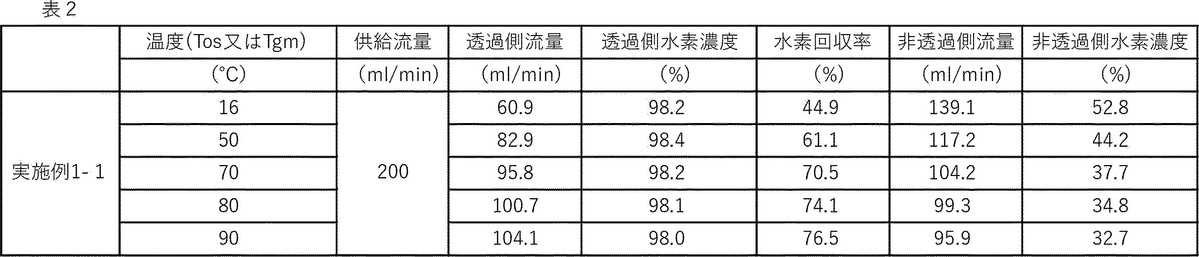
16℃から90℃に加温する事で水素パーミアンスP(H2)は約2倍になり、膜性能あるいは分離モジュール性能が向上した。
また、16℃から90℃に加温する事で酸素パーミアンスP(O2)は約1.6倍にしかならなかった。
結果的に、16℃から90℃に加温する事で、水素酸素間の分離性能α(H2/O2)は、約1.3倍となり、膜性能あるいは分離モジュール性能が向上した。
導出された水素パーミアンスP(H2)の活性化エネルギーEp(H2)は8.9kJ/mol、酸素パーミアンスP(O2)の活性化エネルギーEp(O2)は5.51kJ/molであった。よって、0<Ep(O2)<Ep(H2)であった。
各温度における水素パーミアンスP(H2)と酸素パーミアンスP(O2)は、P(O2)<P(H2)であった。
16℃から90℃に加温する事で水素回収率は約1.7倍に向上した。これに伴い、16℃から90℃に加温する事で非透過側水素濃度は52.8体積%から32.4体積%にまで低減し、万一着火した際の爆轟威力が低減し、安全性が改善した。したがって、16℃から90℃に加温しても透過側水素濃度は約98体積%と安定であって、全温度範囲で化学量論組成の水素酸素混合ガス(水素爆鳴気)の爆発範囲外(95.8体積%超)を安定的に実現できた。
分離膜において、動的分子径の小さな分子のパーミアンスの活性化エネルギーの絶対値は、動的分子径の大きな分子の活性化エネルギーの絶対値に比較して、小さい(温度依存性が小さい)場合が一般的である。しかし、本複合分離膜(表面修飾したCHA型ゼオライト膜/表面修飾CHA膜)においては、それが逆であった事が確認された。
この結果、混合ガス中から相対的に動的分子径の小さい分子を分離・回収する際に、適切な範囲で加温すると、透過側水素濃度をほぼ維持したまま、水素回収率を向上させ、かつ、非透過側の水素濃度も低減可能である事が確認された。

以下の様に、実施例1-1に記載したのと同様の複合分離膜(表面修飾したCHA型ゼオライト膜/表面修飾CHA膜)を6本準備した。これらそれぞれの膜長さを170mmとして加温機構を有する分離モジュール6台にそれぞれ搭載した。図6は当該加温機構を有する分離モジュールの模式図である。当該分離モジュールはその外側に熱媒体として水やフッ素系不活性液体等を流通可能な管状流路を準備し、かつ、それを取り囲むように断熱部を有する構成とした以外は実施例1-1と同様とした。
当該回収システムは規模を拡大すると人工光合成プラント等における水素回収システムとしても使用可能なものである。図4において、本実施例の場合には、加圧機構A及びBは用いず、脱湿機構Aとしてはシリカゲルを搭載した脱湿モジュールを2本使用した。その結果、分離モジュールに導入された混合ガスの相対湿度は全条件において0.1%以下であった。
また、温度調整機構Aは用いず、火炎伝播抑制機構Aとしては、市販の乾式安全器(日酸TANAKA社製/型番:FA-510-H)を使用した。温度調整機構Bとしては図6に示した分離モジュールと一体化した管状流路に恒温槽からの温水を供給して実現した。なお、当該分離モジュールには、脱湿度機構B、火炎伝播抑制機構Bなどは一体化しなかった。また、水素:酸素=2:1の水素酸素混合ガス(水素爆鳴気)の供給圧は図中加圧機構Bとして何も使用せず0kPa(G)とした。また、加圧機構Bの後段には安全性確保のために、市販の乾式安全器(日酸TANAKA社製/型番:FA-510-H)をさらに設置した。また、当該分離膜モジュールの透過側には、減圧機構として最大排気速度120L/minのダイヤフラムポンプを準備し、これによって透過側を-92kPa(G)よりも減圧とした。減圧機構の後段においても安全性確保のために、市販の乾式安全器(日酸TANAKA社製/型番:FA-510-H)をさらに設置した。
ここで、分離モジュールの温度Tosを90℃とし、水素:酸素=2:1の水素酸素混合ガス(水素爆鳴気)を900ml/min供給して、水素回収システムとしてのプロセス性能を評価した。この結果を表4に示す。
減圧機構として準備したダイヤフラムポンプが吸引する透過側の水素濃度は98.2体積%と爆発範囲外であって、水素爆鳴気から安全に水素を分離出来た。また、水素回収率も75.8%と高く、高効率な水素回収が確認された。なお、この際の供給圧は0kPa(G)と十分に低く、水素爆鳴気の供給条件としては理想的であった。
水素:酸素=2:1の水素酸素混合ガス(水素爆鳴気)の供給量を510ml/minとした以外は、実施例1-2の水素回収システムを用いて、プロセス性能を評価した。この結果を表4に示す。
減圧機構として準備した可動部を有するダイヤフラムポンプによって、透過側の圧力は-92.5kPa(G)の減圧であった。また、可動部を有するダイヤフラムポンプが吸引する透過側の水素濃度は96.8体積%と爆発範囲外であって、水素爆鳴気から安全に水素を分離出来た。また、水素回収率も93.7%と非常に高く、超高効率な水素回収が確認された。さらに、可動部をその下流に有さない非透過側の水素濃度も12.1体積%と低く、爆轟範囲外と出来た。このように安全で超高効率な水素酸素分離が実現できた。なお、この際の供給圧は0kPa(G)と十分に低く、水素爆鳴気の供給条件としては理想的であった。
分離モジュール温度を70℃とし、また、水素:酸素=2:1の水素酸素混合ガス(水素爆鳴気)の供給量を450ml/minとした以外は、実施例1-2の水素回収システムを用いて、プロセス性能を評価した。この結果を表4に示す。
減圧機構として準備した可動部を有するダイヤフラムポンプによって透過側の圧力は-94.5kPa(G)の減圧であった。また、可動部を有するダイヤフラムポンプが吸引する透過側の水素濃度は96.6体積%と爆発範囲外であって、水素爆鳴気から安全に水素を分離出来た。また、水素回収率も94.8体積%と非常に高く、超高効率な水素回収が確認された。さらに、可動部をその下流に有さない非透過側の水素濃度も10.0体積%と低く、爆轟範囲外と出来た。このように安全で超高効率な水素酸素分離が実現できた。なお、この際の供給圧は0kPa(G)と十分に低く、水素爆鳴気の供給条件としては理想的であった。
分離モジュール温度を50℃とし、また、水素:酸素=2:1の水素酸素混合ガス(水素爆鳴気)の供給量を300ml/minとした以外は、実施例1-2の水素回収システムを用いて、プロセス性能を評価した。この結果を表4に示す。
減圧機構として準備した可動部を有するダイヤフラムポンプによって透過側の圧力は-95.5kPa(G)の減圧であった。また、可動部を有するダイヤフラムポンプが吸引する透過側の水素濃度は95.9体積%と爆発範囲外であって、水素爆鳴気から安全に水素を分離出来た。また、水素回収率も97.3%と非常に高く、超高効率な水素回収が確認された。さらに、可動部をその下流に有さない非透過側の水素濃度も7.0体積%と非常に低く、爆轟範囲外と出来た。このように安全で超高効率な水素酸素分離が実現できた。なお、この際の供給圧は0kPa(G)と十分に低く、水素爆鳴気の供給条件としては理想的であった。

水熱合成用の反応混合物として、以下のものを調製した。
1mol/L-NaOH水溶液1.44gと1mol/L-KOH水溶液5.76gと水114.01gを混合したものに水酸化アルミニウム(Al2O3 53.5質量%含有、アルドリッチ社製)0.195gを加えて撹拌し溶解させ、透明溶液とした。これに有機テンプレートとして、TMADAOH水溶液(TMADAOH 25質量%含有、セイケム社製)2.43gを加え、さらにコロイダルシリカ(日産化学社製 スノーテック-40)10.8gを加えて30分撹拌し、反応混合物とした。
無機多孔質支持体としてアルミナチューブ(外径12mm、内径9mm)を400mmの長さに切断し用いた。
種結晶として、SiO2/Al2O3/NaOH/KOH/H2O/TMADAOH=1/0.033/0.1/0.06/20/0.07のゲル組成(モル比)で160℃、2日間水熱合成して結晶化させたCHA型ゼオライトを用いた。この種結晶を1.0質量%水中に分散させた分散液に、上記支持体を30秒間浸漬した後引き上げ、無機多孔質支持体上端部に種結晶を担持させ、水熱合成に用いた。
各原料のバブラーからの気体による供給において、窒素ガスを水蒸気の供給に用い、ヘリウムをシリカ源の供給に用いた。反応管は内径15mm、外径20mm、全長440mmのステンレス製管であり、両端はフランジにより気体供給配管と接続でき、反応管内を気体が流通できる。処理は最初の1時間においては水蒸気を同伴する気体のみを供給し、反応管内を流通させ(第1処理段階)、次の5時間においては水蒸気を同伴する気体とポリメトキシシシロキサンを同伴し運搬する気体を混合させ供給し、反応管内を流通させ(第2処理段階)、次の1時間では、水蒸気を同伴する気体のみを供給、反応管内を流通させた(第3処理段階)。処理過程の後、反応管内を放冷した後で、複合分離木を取出し、さらに130℃で1時間加熱処理した(第4処理段階)。
先ず、図4に示した測定系を用いて、分離膜及び分離膜モジュールに水素単体ガス、酸素単体ガスをそれぞれ200ml/minを供給し、それぞれのパーミアンスの活性化エネルギーを求めた。この際、温度調整機構Bとして用いた温度調整可能な水槽温度を16℃~80℃の範囲とした点、供給圧は図中加圧機構Bとして排圧弁を制御し、19kPa(G)とした点、以外は、実施例1-1と同様にして水素単体ガスと、酸素単体ガスそれぞれに対する膜性能(分離モジュール性能)を求めた。この結果を表5にまとめた。
なお、図7は、水素パーミアンスと酸素パーミアンスそれぞれの活性化エネルギーを導出したアレニウスプロットの結果である。この結果導出された水素パーミアンスP(H2)の活性化エネルギーEp(H2)は13.4kJ/mol、酸素パーミアンスP(O2)(mol/(m2・s・Pa))の活性化エネルギーEp(O2)は7.1kJ/molであった。
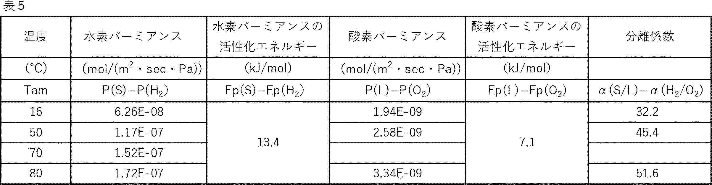
供給圧は図4の加圧機構Bとして排圧弁を制御し、19kPa(G)とした以外は、実施例1-6と同様に、分離対象気体をボンベ供給した水素と酸素の混合気体とし、前者133.3ml/min、後者66.7ml/min、合計200.0ml/minとして分離膜及び分離膜モジュールに供給する方法で水素パーミアンスP(H2)の活性化エネルギーEp(H2)と、酸素パーミアンスP(O2)(mol/(m2・s・Pa))の活性化エネルギーEp(O2)を求めた。この結果を表6にまとめた。なお、図8は、水素パーミアンスと酸素パーミアンスそれぞれの活性化エネルギーを導出したアレニウスプロットの結果である。この結果導出された水素パーミアンスP(H2)の活性化エネルギーEp(H2)は13.5kJ/mol、酸素パーミアンスP(O2)(mol/(m2・s・Pa))の活性化エネルギーEp(O2)は7.2kJ/molであった。
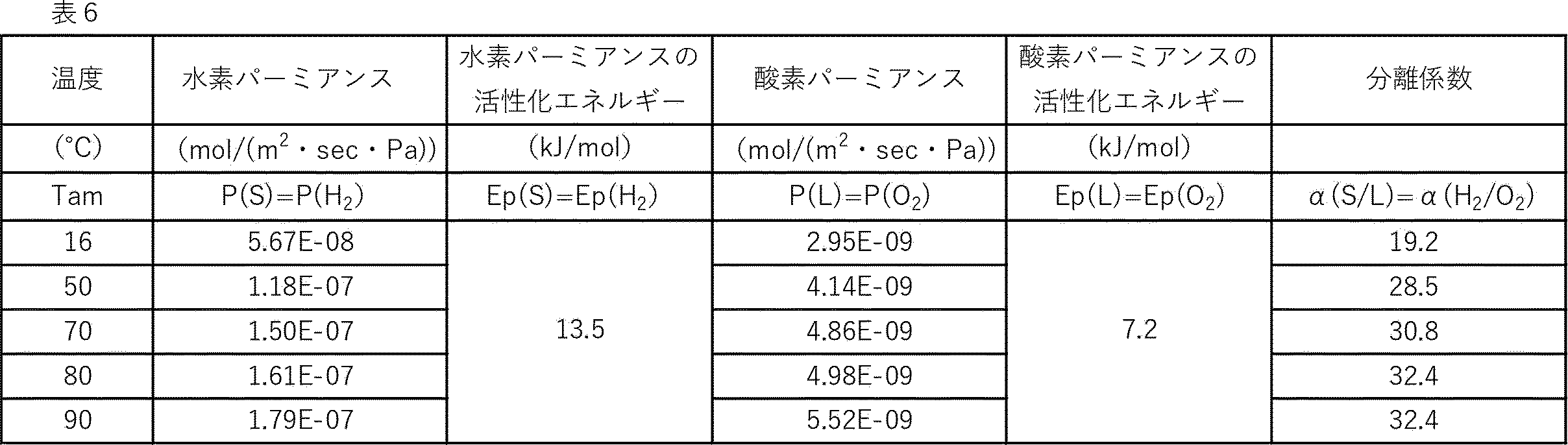
16℃から80℃に加温する事で水素パーミアンスP(H2)は表5に示した単体ガス供給時には約2.7倍、表6に示した混合ガス供給時には約2.8倍となり膜性能あるいは分離モジュール性能が向上した。
16℃から80℃に加温する事で酸素パーミアンスP(O2)は表5に示した単体ガス供給時には約1.7倍、表6に示した混合ガス供給時にも約1.7倍にしかならなかった。
結果的に、16℃から80℃に加温する事で、水素酸素間の分離性能α(H2/O2)は、約1.6~1.7倍となり、膜性能あるいは分離モジュール性能が向上した。
導出された水素パーミアンスP(H2)の活性化エネルギーEp(H2)は単体ガス供給時には13.4kJ/mol、混合ガス供給時には13.5kJ/molであって、酸素パーミアンスP(O2)の活性化エネルギーEp(O2)は単体ガス供給時には7.1kJ/mol、混合ガス供給時には7.2kJ/molであった。よって、いずれの測定条件においても、|Ep(L)|<|Ep(S)|あるいは|Ep(O2)|<|Ep(H2)|であった。
各温度における水素パーミアンスP(H2)と酸素パーミアンスP(O2)は、単体ガス供給時でも、混合ガス供給時でも、P(L)<P(S)あるいはP(O2)<P(H2)であった。
一方、50℃と90℃における混合ガス供給時の水素回収システムとしてのプロセス性能を表7に示す。

50℃から90℃に加温する事で水素回収率は約1.5倍となり、向上した。50℃から90℃に加温しても透過側水素濃度は約98体積%と安定的であって、化学量論組成の水素酸素混合ガス(水素爆鳴気)の爆発範囲外(95.8体積%超)を安定的に実現した。
水素回収システムとしての、あるいは、分離・回収プロセス性能としての特性の改善は複合分離膜(表面修飾したCHA型ゼオライト膜/表面修飾CHA膜)の特異なパーミアンスの温度依存性に帰着するものであって、これまで広く知られている膜性能とは大きく異なるものである。
分離膜において、動的分子径の小さな分子のパーミアンスの活性化エネルギーの絶対値は、動的分子径の大きな分子の活性化エネルギーの絶対値に比較して、小さい(温度依存性が小さい)場合が一般的である。しかし、本複合分離膜(表面修飾したCHA型ゼオライト膜/表面修飾CHA膜)においては、それが逆である事が確認された。この結果、混合ガス中から相対的に動的分子径の小さい分子を分離・回収する際に、適切な範囲で加温すると、透過側水素濃度をほぼ維持したまま、水素回収率を向上させ、かつ、非透過側の水素濃度も低減可能である事が確認された。
実施例1-1と同様にして得られた400cm長CHA型ゼオライト単体分離構造1本を200mm長に2分割して、そのうち1本の200mm長CHA型ゼオライト単体分離構造を、図2に示す原料供給気体流通式ゼオライト単体分離構造上端部処理装置の反応管に入れた。当該反応管内の処理(表面修飾処理)は、200cm長の膜試料の本数を1本とし、窒素ガスをシリカ源の供給にも用いたこと以外は実施例1-1と同様にして行った。
処理過程の後、反応管内を放冷した後で、複合分離膜を取り出した。ここで200mm長の複合分離膜が1本準備された。この複合分離膜を膜長さ17.5cmとして分離膜モジュール内に装着し、気体分離実験の準備を完了した。
当該複合分離膜(表面修飾したCHA型ゼオライト膜/表面修飾CHA膜)の膜性能評価と、水素/窒素分離実験を行った。また、その結果を元に水素パーミアンスP(H2)(mol/(m2・s・Pa))の活性化エネルギーEp(H2)(kJ/mol)と、窒素パーミアンスP(N2)(mol/(m2・s・Pa))の活性化エネルギーEp(N2)とを導出した。当該導出においては、供給ガスは水素:窒素=2:1の水素窒素混合ガスとし、図4に示した測定系を用いた。
なお、図9は、水素パーミアンスと窒素パーミアンスそれぞれの活性化エネルギーを導出したアレニウスプロットの結果である。この結果導出された水素パーミアンスP(H2)の活性化エネルギーEp(H2)は10.0kJ/mol、酸素パーミアンスP(O2)(mol/(m2・s・Pa))の活性化エネルギーEp(O2)は0.8kJ/molであった。

分離膜において、動的分子径の小さな分子のパーミアンスの活性化エネルギーの絶対値は、動的分子径の大きな分子の活性化エネルギーの絶対値に比較して、小さい(温度依存性が小さい)場合が一般的である。しかし、本複合分離膜(表面修飾したCHA型ゼオライト膜/表面修飾CHA膜)において、水素、酸素、窒素の二原子分子間においては、それが逆である事が確認された。
すなわち、水素の動的分子径は2.89A、酸素の動的分子径は3.46A、窒素の動的分子径は3.64Aであって、従来の知見からは、水素パーミアンスの活性化エネルギーが最も小さく、次いで酸素パーミアンスの活性化エネルギー、窒素パーミアンスの活性化エネルギーは最も大きいと考えられる。しかし、本複合分離膜(表面修飾したCHA型ゼオライト膜/表面修飾CHA膜)ではこの結果が逆であった。具体的には、水素パーミアンスの活性化エネルギーが最も大きく8.9~10.0kJ/mol、次いで酸素パーミアンスの活性化エネルギーが5.5kJ/mol、窒素パーミアンスの活性化エネルギーは最も小さく0.8kJ/molであった。
なお、この結果からは、例えば、空気から酸素と窒素を分離するような空気分離を想定する際にも、複合分離膜用いた加温分離によって、高効率に酸素と窒素を分離する事が可能になると考えられる。すなわち、単純な分子篩ではない複合的現象によって、前述のガスパーミアンスの活性化エネルギーの傾向が発現する可能性のある、例えば、CHA型ゼオライト膜上に形成されたシリカ修飾部を有する複合分離膜、CHA型以外の各種ゼオライト膜上に形成されたシリカ修飾部を有する複合分離膜、ゼオライト膜上に形成された炭素ネットワークを有する複合分離膜、各種CVD/ゾルゲル法で作製されたシリカ膜上に形成された炭素ネットワークを有する複合分離膜、炭素膜上に形成されたシリカ修飾部を有する複合分離膜等の複合的構造を有する分離膜などにおいて、同様の特性が発現する可能性が考えられる。すなわち、第一分離部と第二分離部におけるそれぞれのガス吸着特性、ガス拡散特性、ガス脱着特性等、ガス分離特性に係る特性が異なる場合、また、第二分離部が第一分離部の特性を遮蔽するなどの相互作用がある場合に、このようなガスパーミアンスの活性化エネルギーの傾向が発現する可能性があると推察される。このような分離膜を用いた酸素と窒素の分離や空気分離においては、適切な加温分離が高選択かつ高回収な分離を実現できると推察される。
供給ガスを水素:窒素=2:1の水素窒素混合ガスから、単体の水素ガス、二酸化炭素ガス、アルゴンガス、窒素ガス、メタンガスに変更し、かつ、温度調整機構Bとして用いた温度調整可能なオーブン温度を30℃~100℃の範囲とした点以外は、実施例1-7と同様にして、複合分離膜の膜性能(分離モジュール性能)を測定した。この結果を表9にまとめた。

分離膜において、動的分子径の小さな分子のパーミアンスの活性化エネルギーの絶対値は、動的分子径の大きな分子の活性化エネルギーの絶対値に比較して、小さい(温度依存性が小さい)場合が一般的である。しかし、本複合分離膜(表面修飾したCHA型ゼオライト膜/表面修飾CHA膜)において、動的分子径が相対的に小さい分子として水素が含まれ、動的分子径が相対的に大きい分子として二酸化炭素、アルゴン、酸素、窒素、メタンの中から選択される少なくとも1種類のガスが含まれて混合ガスが構成される場合、当該混合ガスから水素を分離・回収する際には適切な範囲で加温すると、透過側水素濃度を高い水準で維持しながら、水素回収率を向上させ、かつ、非透過側の水素濃度も低減可能である事が期待される。
以下の様に、膜長さを1mとした以外は、実施例1-7と同等の性能を有する複合分離膜(表面修飾したCHA型ゼオライト膜/表面修飾CHA膜)を仮定し、以下の通りに計算によって30℃、80℃、130℃における水素窒素混合ガスに対して期待される分離プロセス性能を導出した。
計算にはいわゆる両側プラグフローモデルを用い、水素窒素混合ガスの供給流量を900mL/min、水素:窒素=1:1、複合分離膜の膜長さを1m、図4の加圧機構Bにより供給圧を0.1MPa(G)、減圧機構として真空ポンプによって透過側は-0.09MPa(G)とした。この結果を表10にまとめた。

水熱合成用の反応混合物として、以下のものを調製した。
1mol/L-NaOH水溶液21.6gと1mol/L-KOH水溶液86.4gと水1710.2gを混合したものに水酸化アルミニウム(Al2O3 53.5質量%含有、アルドリッチ社製)2.925gを加えて撹拌し溶解させ、透明溶液とした。これに有機テンプレートとして、TMADAOH(N,N,N-Trimethyl-1-adamantylammonium Hydroxide)水溶液(TMADAOH 25質量%含有、セイケム社製)36.45gを加え、さらにコロイダルシリカ(日産化学社製 スノーテック-40)162gを加えて30分撹拌し、反応混合物とした。
無機多孔質支持体としてアルミナチューブ(外径12mm、内径9mm)を1000mmの長さに切断し用いた。
種結晶として、SiO2/Al2O3/NaOH/KOH/H2O/TMADAOH=1/0.033/0.1/0.06/20/0.07のゲル組成(モル比)で160℃、2日間水熱合成して結晶化させたCHA型ゼオライトを用いた。この種結晶を1.0質量%水中に分散させた分散液に、上記支持体を30秒間浸漬した後引き上げ、無機多孔質支持体上端部に種結晶を担持させ、水熱合成に用いた。
膜性能評価実験においては、分離対象気体をボンベ供給した水素と酸素の混合気体とし、前者を100ml/min、後者を50ml/minとして計150ml/minを分離膜及び分離膜モジュールに供給した。当該分離対象混合気体はその組成を水素:酸素=2:1の化学量論組成とした。これは、光触媒材料を搭載した人工光合成プラント等における水の全分解から発生する水素と酸素を想定したものである。一方、水素/酸素分離実験(プロセス性能確認実験)においては、同様に分離対象気体をボンベ供給した水素と酸素の混合気体としたものの、前者を60ml/min、後者を30ml/minとし、供給総流量は計90ml/minに変更して分離膜及び分離膜モジュールに供給した。
評価に使用した測定系の模式図を図4に示す。当該測定系は規模を拡大すると人工光合成プラント等における水素回収システムとしても使用可能なものである。この際、加圧機構Aは用いず、脱湿機構Aとしてはシリカゲルを搭載した脱湿モジュールを使用した。この結果、分離モジュールに導入された混合ガスの相対湿度は全条件において0.1%以下であった。温度調整機構Aは用いず、火炎伝播抑制機構Aとしては、ジルコンビーズを配管内に詰めた充填配管と破裂板をエルボ配管で結合したものを使用した。温度調整機構Bとしては温度調整可能な水槽を用い、前記分離モジュールをこの中に設置する事で、50℃、70℃、90℃における当該複合分離膜(表面修飾したCHA型ゼオライト膜/表面修飾CHA膜)の膜性能評価と、水素/酸素分離実験を行った。なお、当該分離モジュールには、脱湿度機構B、可燃伝播抑制機構Bなどは一体化しなかった。
供給圧は図中加圧機構Bとして排圧弁を制御し、20kPa(G)とした。さらに、当該分離膜モジュールの透過側には、減圧機構として最大排気速度580L/minのスクロールポンプを準備し、これによって透過側を約-99kPa(G)の減圧とした。
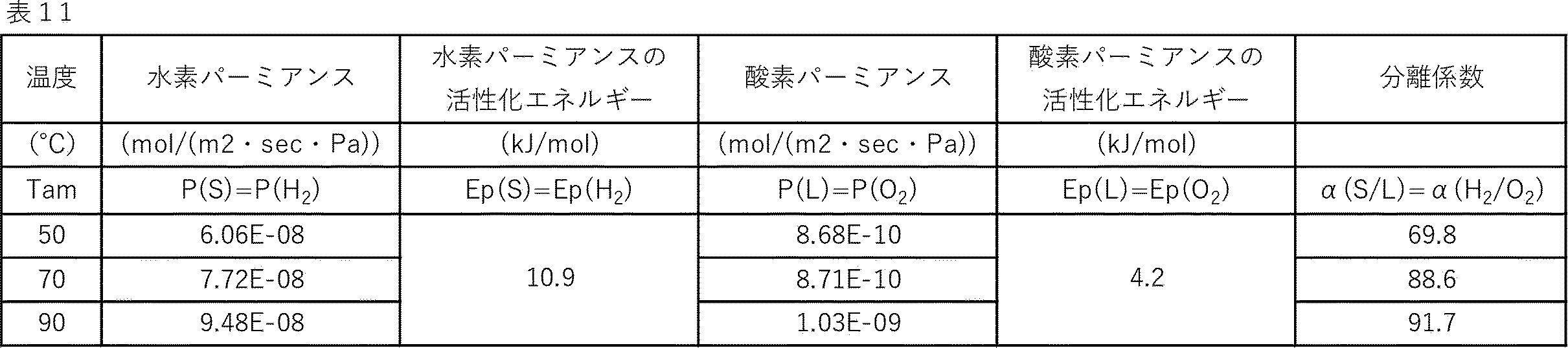

透過側水素濃度が約97.7体積%であった。同時に非透過側水素濃度が約3.4体積%であった。ここで、水素酸素混合ガスの爆発範囲は3.9体積%~95.8体積%であると考えられているが、透過側水素濃度/非透過側水素濃度とも爆発範囲の上限/下限をそれぞれ外れていた事が確認された。すなわち、水素爆鳴気(水素:酸素=2:1の気体)を透過側、非透過側とも爆発しない組成の水素酸素混合ガスに分離する事に成功した。換言すると透過側は約97.7体積%の水素であって、非透過側は水素が約3.4体積%残留しているものの約96.6体積%は酸素であった。また、水素回収率は約98.3%と超高回収率であった事が確認された。
表面修飾を施さずゼオライト単体分離構造(未修飾CHA膜)を用いた点、分離モジュール内で当該ゼオライト単体分離構造の表面が露出した長さは57mmとした点、安全性の観点から、水素と酸素の混合ガスではなく、水素単体ガスと窒素単体ガスを用いた点、測定した温度範囲を50℃~140℃とした点、の4点以外は、実施例1-6と同様にして水素パーミアンスP(H2)(mol/(m2・s・Pa))の活性化エネルギーEp(H2)(kJ/mol)と、窒素パーミアンスP(N2)(mol/(m2・s・Pa))の活性化エネルギーEp(N2)を導出した。

すなわち、導出された水素パーミアンスP(H2)の活性化エネルギーEp(H2)は単体ガス供給時に-4.1kJ/mol、窒素パーミアンスP(N2)の活性化エネルギーEp(N2)は単体ガス供給時には-9.5kJ/molであった。よって、Ep(N2)<Ep(H2)<0であって、|Ep(H2)|<|Ep(N2)|であった。
この結果、混合ガス中から相対的に動的分子径の小さい分子を分離・回収する際に加温すると、選択性は向上するものの、透過側水素量が確認された。
図12に限界消炎圧力を求めるための実験装置の模式図を示す。
内部空間が直径約6cm、高さ約15.5cmの円筒であり、その中間部に、小粒径無機粒子を搭載したセルを設置できるSUS製の爆発実験容器200を準備した。当該容器中の無機粒子搭載セル201は、ある程度の火炎伝播抑制機能を有するもので、その消炎能力は容器内に充満される水素酸素混合気体の水素酸素混合比、温度、圧力、搭載する無機粒子の粒径、充填密度、形状等によって決定される。
ここで爆発/爆轟威力の相対的温度依存性の評価では、水素酸素混合比を最も条件の厳しい化学量論組成(水素:酸素=2:1)とし、無機粒子の粒径、充填密度、形状等を一定として固定的な消炎性能を無機粒子搭載セルに持たせ、かつ、温度を固定し、水素酸素混合気体の圧力を変化させると、当該無機粒子搭載セル201とその温度において消炎可能な温度の上限を知る事ができる。当該圧力をその温度における「消炎限界圧力」とする。
次いで、前記と同等の無機粒子搭載セル201を用いて、前記と異なる温度においてその温度における「消炎限界圧力」を求める。これを繰り返す事で、複数の温度水準における消炎限界圧力が得られる事になる。ここにおいて、消炎限界圧力が高い場合には、その温度における水素酸素混合気体の爆発威力は低いために、圧力を上げても消炎可能であると理解できる。一方、消炎限界圧力が低い場合には、逆に、その温度における水素酸素混合気体の爆発威力は高いために、圧力を上げる事は出来ずに、相対的に低い圧力でないと消炎する事ができないものと理解できる。
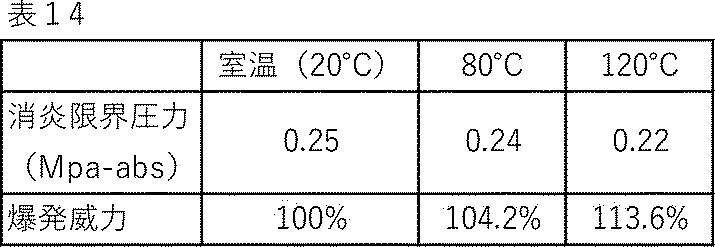
よって、温度による爆轟威力の増大はこれより小さくする事が望まれ、当該増大が、30%以内である事が好ましく、20%以内である事がより好ましく、15%以内である事がさらに好ましく、12%以内である事が最も好ましい。これを図6よりおおよそ温度に換算すると、ぞれぞれ、220℃以下が好ましく、150℃以下がより好ましく、120℃以下がさらに好ましく、95℃以下が最も好ましい。
水熱合成用の反応混合物として、以下のものを調製した。
1mol/L-NaOH水溶液7.2gと1mol/L-KOH水溶液28.8gと水570.05gを混合したものに水酸化アルミニウム(Al2O3 53.5質量%含有、アルドリッチ社製)0.975gを加えて撹拌し溶解させ、透明溶液とした。これに有機テンプレートとして、TMADAOH(N,N,N-Trimethyl-1-adamantylammonium Hydroxide)水溶液(TMADAOH 25質量%含有、セイケム社製)12.15gを加え、さらにコロイダルシリカ(日産化学社製 スノーテック-40)54gを加えて30分撹拌し、反応混合物とした。
無機多孔質支持体としてアルミナチューブ(外径12mm、内径9mm)を400mmの長さに切断し用いた。
種結晶として、SiO2/Al2O3/NaOH/KOH/H2O/TMADAOH=1/0.033/0.1/0.06/20/0.07のゲル組成(モル比)で160℃、2日間水熱合成して結晶化させたCHA型ゼオライトを用いた。この種結晶を1.0質量%水中に分散させた分散液に、上記支持体を30秒間浸漬した後引き上げ、無機多孔質支持体上端部に種結晶を担持させ、水熱合成に用いた。
実験においては、分離対象気体をボンベ供給した水素と酸素の混合気体とし、前者を133.3ml/min、後者を66.7ml/minとして計200.0ml/minを分離膜及び分離膜モジュールに供給した。当該分離対象混合気体はその組成を水素:酸素=2:1の化学量論組成とした。これは、光触媒材料を搭載した人工光合成プラント等における水の全分解から発生する水素と酸素を想定したものである。
評価に使用した測定系の模式図を図4に示す。当該測定系は規模を拡大すると人工光合成プラント等における水素回収システムとしても使用可能なものである。この際、加圧機構Aは用いず、脱湿機構Aとしてはシリカゲルを搭載した脱湿モジュールを使用した。この結果、分離モジュールに導入された混合気体の相対湿度は全条件において0.1%以下であった。温度調整機構Aは用いず、火炎伝播抑制機構Aとしては、ジルコンビーズを配管内に詰めた充填配管と破裂板をエルボ配管で結合したものを使用した。温度調整機構Bとしては温度調整可能な水槽を用い、前記分離モジュールをこの中に設置する事で、20℃、51℃、70℃、80℃、90℃における当該複合分離膜(表面修飾したCHA型ゼオライト膜/表面修飾CHA膜)の膜性能評価と、水素/酸素分離実験を行った。なお、当該分離モジュールには、脱湿度機構B、可燃伝播抑制機構Bなどは一体化しなかった。
供給圧は図中加圧機構Bとして排圧弁を制御し、20kPa(G)とした。さらに、当該分離膜モジュールの透過側には、減圧機構として最大排気速度580L/minのスクロールポンプを準備し、これによって透過側を約-99kPa(G)の減圧とした。
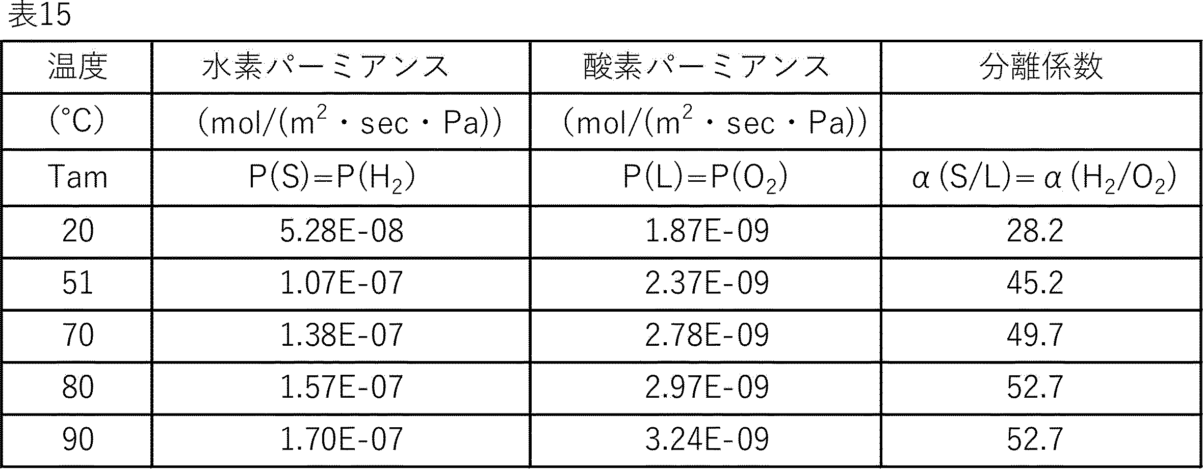

20℃から90℃に加温する事で水素パーミアンスP(H2)は約3倍になり、膜性能あるいは分離モジュール性能が向上した。一方、20℃から90℃に加温する事で酸素パーミアンスP(O2)は約1.7倍にしかならなかった。
結果的に、20℃から90℃に加温する事で、水素酸素間の分離性能α(H2/O2)は、約1.9倍となり、膜性能あるいは分離モジュール性能が向上した。
また、各温度における水素パーミアンスP(H2)と酸素パーミアンスP(O2)は、P(O2)<P(H2)であった。
20℃を基準に考えると、90℃に加温する事で水素回収率は約2.7倍に向上した。これに伴い、20℃から90℃に加温する事で非透過側水素濃度は60.3体積%から40.1体積%にまで低減し、万一着火した際の爆轟威力が低減し、安全性が改善した。20℃から90℃に加温しても透過側水素濃度は約98体積%と安定であって、全温度範囲で化学量論組成の水素酸素混合気体(水素爆鳴気)の爆発範囲外(95.8体積%超)を安定的に実現できた。
このように20℃から90℃に加温した場合において、供給側水素酸素混合気体に万一着火した際の爆発威力を考えると、実施例2-1の結果から6~7%程度の増大と推察されるが、その影響は十分に小さいと言える。よって、適正範囲で加温分離する事による前記利点を合わせて考えると、その有効性は明らかである。
これらの結果より、20℃から51℃に加温する事で水素パーミアンスP(H2)は約2倍になり、膜性能あるいは分離モジュール性能が向上した。一方、20℃から51℃に加温する事で酸素パーミアンスP(O2)は約1.3倍にしかならなかった。
結果的に、20℃から51℃に加温する事で、水素酸素間の分離性能α(H2/O2)は、約1.6倍となり、膜性能あるいは分離モジュール性能が向上した。
また、各温度における水素パーミアンスP(H2)と酸素パーミアンスP(O2)は、P(O2)<P(H2)であった。
20℃を基準に考えると、51℃に加温する事で水素回収率は約1.9倍に向上した。これに伴い、20℃から51℃に加温する事で非透過側水素濃度は60.3体積%から51.8体積%にまで低減し、万一着火した際の爆轟威力が低減し、安全性が改善した。20℃から51℃に加温しても透過側水素濃度は約98体積%と安定であって、全温度範囲で化学量論組成の水素酸素混合気体(水素爆鳴気)の爆発範囲外(95.8体積%超)を安定的に実現できた。
このように20℃から51℃に加温した場合において、供給側水素酸素混合気体に万一着火した際の爆発威力を考えると、実施例2-1の結果から2~3%程度の増大と推察されるが、その影響は十分に小さいと言える。よって、加温分離する事による前記利点を合わせて考えると、その有効性は明らかである。
以下の様に、実施例2-2に記載したのと同様の複合分離膜(表面修飾したCHA型ゼオライト膜/表面修飾CHA膜)を6本準備した。これらそれぞれの膜長さを170mmとして加温機構を有する分離モジュール6台にそれぞれ搭載した。
当該回収システムは規模を拡大すると人工光合成プラント等における水素回収システムとしても使用可能なものである。図4において、本実施例の場合には、加圧機構A及びBは用いず、脱湿機構Aとしてはシリカゲルを搭載した脱湿モジュールを2本使用した。その結果、分離モジュールに導入された混合気体の相対湿度は全条件において0.1%以下であった。
ここで、分離モジュールの温度Tosを90℃とし、水素:酸素=2:1の水素酸素混合気体(水素爆鳴気)を480ml/min供給して、水素回収システムとしてのプロセス性能を評価した。
実施例2-1の結果から、90℃に加温した場合において、仮に室温時に供給側水素酸素混合気体に着火した際の爆発威力と比較すると、6~7%程度の増大と推察され、その影響は十分に小さいと言える。よって、適正範囲で加温分離する事による前記利点を合わせて考えると、その有効性は明らかである。
また、本発明によれば、従来温度を上げると危険だと思われていた水素酸素混合気体を、従来行われていなかった高い温度の分離膜で分離を行うことにより、水素と酸素を含む混合気体からの水素の分離が十分に行われることにより、分離膜透過後の酸素濃度が十分低下し、爆轟範囲から外れるため、かえって安全に分離することが可能になった。水素酸素分離を行う部分は、多くの水素酸素混合気体の発生装置(例えば人工光合成の光触媒による水の分解装置)からの水素酸素混合気体が集まってくる場所であり、ここで本発明を適用することにより、分離対象となる大量の混合気体が分離工程通過後に爆轟範囲から外れ、これにより水素及び酸素を含む混合気体から水素を安全に分離・回収することができる。本技術と例えば、太陽光などの再生可能エネルギーを用いて水の電気分解を行う方法、光触媒による水の全分解によって水素と酸素を同時に発生させる方法とを組み合わせることで、いわゆるグリーン水素を効率的に分離・回収することができる。
したがって、本発明は技術的にも、環境的にも有用な発明であって、工業的価値の高い技術である。
2.水から水蒸気を発生させる容器(バブラー)
3.管状反応管
4.気体流量制御計
5.排気気体中の水蒸気捕集器
6.背圧弁
7.気体流量計
8.バルブ
9.供給気体
10.排気気体
11.恒温槽
21.管状反応管
22.ゼオライト単体分離構造
23.固定ジグ
24.フランジ
25.供給気体導入配管
26.排気気体用配管
100.複合分離膜
101.支持体
102.空隙部
103.第一分離部
104.第二分離部
105.分離活性部
106.単体分離構造
200.限界消炎圧力測定装置
201.無機粒子搭載セル
202.第1燃焼室
203.第2燃焼室
204.圧力検出器
205.熱電対
206.点火用ネオントランス
Claims (56)
- 下記式(1-I)を満たす温度Tam(℃)の範囲内で導出される、分離膜に対する水素のパーミアンスP(S)(mol/(m2・s・Pa))の活性化エネルギーEp(S)(kJ/mol)と、同じ温度範囲内で導出される当該分離膜に対する気体L(但し、Lは二酸化炭素、アルゴン、酸素、窒素、及びメタンからなる群から選ばれる少なくとも1種)のパーミアンスP(L)(mol/(m2・s・Pa))の活性化エネルギーEp(L)(kJ/mol)とが、下記式(1-II)を満たす分離膜。
5(℃)≦Tam(℃)≦200(℃)・・・(1-I)
|Ep(L)|<|Ep(S)|・・・(1-II) - 下記式(1-III)を満たす、請求項1に記載の分離膜。
P(L)<P(S)・・・(1-III) - 下記式(1-IV)を満たす、請求項1に記載の分離膜。
0<Ep(L)<Ep(S)・・・(1-IV) - 無機膜である、請求項1に記載の分離膜。
- 表面修飾したゼオライト膜を有する、請求項1に記載の分離膜。
- 支持体上に分離膜を備えた分離膜積層体であって、前記分離膜が請求項1~5のいずれか1項に記載の分離膜であり、前記支持体が管状であり、かつ該支持体の内径φi(mm)が、下記式(1-VI)を満たす、分離膜積層体。
6(mm)≦φi(mm)≦16(mm)・・・(1-VI) - 分離膜を搭載した分離モジュール又は分離塔であって、前記分離膜が請求項1~5のいずれか1項に記載の分離膜であり、
かつ、当該分離モジュール又は分離塔の温度Tos(℃)が下記式(1-VII)を満たす、分離モジュール又は分離塔。
45(℃)≦Tos(℃)≦200(℃)・・・(1-VII) - 前記分離モジュール又は分離塔の内壁と、当該内壁に最も近接する分離膜との間隔が0.1cm以上50cm以下である、請求項7に記載の分離モジュール又は分離塔。
- 請求項6に記載の分離膜積層体を搭載した分離モジュール又は分離塔であって、
当該分離モジュール又は分離塔の温度Tos(℃)が下記式(1-VII)を満たす、分離モジュール又は分離塔。
45(℃)≦Tos(℃)≦200(℃)・・・(1-VII) - 脱湿機構、加温機構、及び火炎伝播抑制機構の少なくともいずれか一つをさらに有する、請求項7に記載の分離モジュール又は分離塔。
- 分離膜を搭載した水素回収システムであって、該分離膜が請求項1~5のいずれか1項に記載の分離膜であり、
当該水素回収システムにおいて分離・回収対象である混合気体Mの温度、又は当該分離膜の温度、の少なくとも一方の温度Tgm(℃)が、下記式(1-IX)を満たす、水素回収システム。
45(℃)≦Tgm(℃)≦200(℃)・・・(1-IX) - 請求項6に記載の分離膜積層体を備える、水素回収システムであって、
当該水素回収システムにおいて分離・回収対象である混合気体Mの温度、又は当該分離膜の温度、の少なくとも一方の温度Tgm(℃)が、下記式(1-IX)を満たす、水素回収システム。
45(℃)≦Tgm(℃)≦200(℃)・・・(1-IX) - 前記分離膜が分離モジュール又は分離塔に搭載され、該分離膜モジュール又は分離塔の内壁と、当該内壁に最も近接する当該分離膜との間隔が0.1cm以上50cm以下である、請求項11に記載の水素回収システム。
- 前記分離膜に供給する前記混合気体Mに対する加圧機構を有する、請求項11に記載の水素回収システム。
- 脱湿機構、加温機構、及び火炎伝播抑制機構の少なくともいずれか一つをさらに有する、請求項11に記載の水素回収システム。
- 前記分離膜の透過側に減圧機構を有する、請求項11に記載の水素回収システム。
- 分離膜によって、水素と水素より動的分子径が大きい気体L1の混合気体Mから水素を分離・回収する方法であって、
該分離膜が請求項1~5のいずれか1項に記載の分離膜であり、
かつ、前記混合気体Mの温度、又は当該分離膜の温度、の少なくとも一方の温度Tgm(℃)が、下記式(1-IX)を満たす、水素を分離・回収する方法。
45(℃)≦Tgm(℃)≦200(℃)・・・(1-IX) - 前記分離膜に供給する混合気体Mの圧力FM(MPa(G))が、下記式(1-XI)を満たす、請求項17に記載の水素を分離・回収する方法。
0.0(MPa(G))≦FM(MPa(G))≦0.2(MPa(G))・・・(1-XI) - 前記分離膜の透過側を減圧にする、請求項17に記載の水素を分離・回収する方法。
- 前記分離膜の透過側圧力が、-0.101MPa(G)以上、-0.065MPa(G)以下である、請求項19に記載の水素を分離・回収する方法。
- 混合気体Mにおける相対湿度RHM(%)が、下記式(1-XIII)を満たす、請求項17に記載の水素を分離・回収する方法。
0.0(%)≦RHM(%)≦5(%)・・・(1-XIII) - 前記混合気体Mの温度、又は当該分離膜の温度、の少なくとも一方の温度Tgm(℃)が、下記式(1-IX)を満たすように加温する、請求項18に記載の水素を分離・回収する方法。
45(℃)≦Tgm(℃)≦200(℃)・・・(1-IX) - 混合気体Mが火炎伝播抑制機構を通過後に分離膜を通過する、請求項17に記載の水素を分離・回収する方法。
- 前記分離膜を搭載する分離膜モジュール又は分離塔を有し、該分離膜モジュール又は分離塔における供給側最大レイノルズ数を5以上2000以下及び/又は透過側最大レイノルズ数を5以上2000以下とするように混合気体Mを供給する、請求項17に記載の水素を分離・回収する方法。
- 前記気体Lが酸素であって、分離・回収工程後の透過側の水素酸素混合ガスの水素濃度を95.8体積%超とするように水素酸素混合気体を供給する、請求項17に記載の水素を分離・回収する方法。
- 前記分離・回収工程後の透過側の水素酸素混合ガスの水素濃度を96.0体積%以上、非透過側の水素酸素混合ガスの水素濃度を15.5体積%以下とするように水素酸素混合気体を供給する、請求項25に記載の水素を分離・回収する方法。
- 下記式(1-I)を満たす温度Tam(℃)の範囲内で導出される、分離膜に対する水素のパーミアンスP(S)(mol/(m2・s・Pa))の活性化エネルギーEp(S)(kJ/mol)と、同じ温度範囲内で導出される当該分離膜に対する気体L(但し、水素を除く)のパーミアンスP(L)(mol/(m2・s・Pa))の活性化エネルギーEp(L)(kJ/mol)とが、下記式(1-II)を満たす分離膜。
5(℃)≦Tam(℃)≦200(℃)・・・(1-I)
|Ep(L)|<|Ep(S)|・・・(1-II) - 少なくとも水素及び酸素を含む混合気体Mから水素を分離・回収する方法であって、当該分離・回収工程における温度Tgm(℃)が下記式(2-I)を満たす、分離・回収方法。
45(℃)≦Tgm(℃)≦200(℃)・・・(2-I) - 前記分離・回収工程に供給する混合気体M中の水素と酸素の組成比が2対1、又はそれ以上に水素過多である、請求項28に記載の分離・回収方法。
- 前記分離・回収工程に供給する混合気体Mが爆発範囲内である、請求項28に記載の分離・回収方法。
- 前記分離・回収工程に分離膜を用いる、請求項28に記載の分離・回収方法。
- 前記分離膜が無機膜である、請求項31に記載の分離・回収方法。
- 前記分離膜が表面修飾したゼオライト膜を有する、請求項32に記載の分離・回収方法。
- 前記分離膜がポリイミド膜またはポリアミド膜である、請求項31に記載の分離・回収方法。
- 前記分離膜に供給する混合気体Mの圧力FM(MPa(G))が下記式(2-III)を満たす、請求項31に記載の分離・回収方法。
0.0(MPa(G))≦FM(MPa(G))≦0.2(MPa(G))・・・(2-III) - 前記分離膜の透過側を減圧する、請求項31に記載の分離・回収方法。
- 前記分離膜の透過側圧力が-0.9MPa(G)よりも低い、請求項36に記載の分離・回収方法。
- 前記混合気体Mにおける相対湿度RHM(%)が、下記式(2-V)を満たす、請求項31に記載の分離・回収方法。
0.0(%)≦RHM(%)≦5.0(%)・・・(2-V) - 温度Tgmが上記式(2-I)を満たすように前記混合気体M、前記分離膜の少なくとも一方を加温する、請求項31に記載の分離・回収方法。
- 混合気体Mが火炎伝播抑制機構を通過後に分離膜を通過する、請求項31に記載の分離・回収方法。
- 供給側最大レイノルズ数及び/又は透過側最大レイノルズ数を5以上2000以下とするように混合気体Mを供給する、請求項31に記載の分離・回収方法。
- 分離・回収工程における透過後の混合気体の水素濃度が95.8体積%超となるように混合気体Mを供給する、請求項31に記載の分離・回収方法。
- 分離・回収工程後の透過側の混合気体の水素濃度が96.0体積%以上、非透過側の混合気体の水素濃度が15.5体積%以下となるように混合気体Mを供給する、請求項42に記載の分離・回収方法。
- 少なくとも水素及び酸素を含む混合気体Mから水素を分離・回収する分離モジュール又は分離塔であって、温度調整機構を有する分離モジュール又は分離塔。
- 前記温度調整機構が、熱媒体を流通する管状流路及び/または断熱部を含む、請求項44に記載の分離モジュール又は分離塔。
- 前記分離モジュール又は分離塔のいずれかの温度Tos(℃)が下記式(2-VII)を満たす、請求項44に記載の分離モジュール又は分離塔。
51(℃)≦Tos(℃)≦220(℃)・・・(2-VII) - 前記分離モジュール又は分離塔が分離膜を搭載する、請求項44に記載の分離モジュール又は分離塔。
- 前記分離膜が無機膜である、請求項47に記載の分離モジュール又は分離塔。
- 前記分離膜が表面修飾したゼオライト膜を有する、請求項47に記載の分離モジュール又は分離塔。
- 前記分離モジュール又は分離塔の内壁と該内壁に最も近接する分離膜との間隔が0.1cm以上50cm以下である、請求項47に記載の分離モジュール又は分離塔。
- 前記分離膜が管状の支持体を有し、該支持体の内径φi(mm)が下記式(2-IX)を満たす、請求項47に記載の分離モジュール又は分離塔。
6≦φi≦16・・・(2-IX) - 少なくとも水素及び酸素を含む混合気体Mから水素を分離・回収する水素回収システムであって、請求項44~51のいずれか1項に記載の分離モジュール又は分離塔を有する水素回収システム。
- 前記分離モジュール又は分離塔に供給する混合気体Mに対する加圧機構を有する、請求項52に記載の水素回収システム。
- 混合気体Mの脱湿部及び/または混合気体Mの加温部を有する、請求項52に記載の水素回収システム。
- 火炎伝播抑制部を有する、請求項52に記載の水素回収システム。
- 前記分離モジュール又は分離塔よりも下流側に減圧機構を有する、請求項52に記載の水素回収システム。
Priority Applications (4)
| Application Number | Priority Date | Filing Date | Title |
|---|---|---|---|
| CN202480043557.5A CN121419827A (zh) | 2023-06-30 | 2024-06-28 | 分离膜、分离膜层叠体、分离模块或分离塔、氢气回收系统以及分离/回收氢气的方法 |
| JP2025530250A JPWO2025005285A1 (ja) | 2023-06-30 | 2024-06-28 | |
| EP24832141.6A EP4736995A1 (en) | 2023-06-30 | 2024-06-28 | Separation membrane, separation membrane layered body, separation module or separation tower, hydrogen recovery system, and hydrogen separation and recovery method |
| US19/431,272 US20260115671A1 (en) | 2023-06-30 | 2025-12-23 | Separation membrane, separation membrane layered body, separation module or separation tower, hydrogen recovery system, and hydrogen separation and recovery method |
Applications Claiming Priority (4)
| Application Number | Priority Date | Filing Date | Title |
|---|---|---|---|
| JP2023-108758 | 2023-06-30 | ||
| JP2023108758 | 2023-06-30 | ||
| JP2023-108757 | 2023-06-30 | ||
| JP2023108757 | 2023-06-30 |
Related Child Applications (1)
| Application Number | Title | Priority Date | Filing Date |
|---|---|---|---|
| US19/431,272 Continuation US20260115671A1 (en) | 2023-06-30 | 2025-12-23 | Separation membrane, separation membrane layered body, separation module or separation tower, hydrogen recovery system, and hydrogen separation and recovery method |
Publications (1)
| Publication Number | Publication Date |
|---|---|
| WO2025005285A1 true WO2025005285A1 (ja) | 2025-01-02 |
Family
ID=93938552
Family Applications (1)
| Application Number | Title | Priority Date | Filing Date |
|---|---|---|---|
| PCT/JP2024/023643 Ceased WO2025005285A1 (ja) | 2023-06-30 | 2024-06-28 | 分離膜、分離膜積層体、分離モジュール又は分離塔、水素回収システム及び水素を分離・回収する方法 |
Country Status (5)
| Country | Link |
|---|---|
| US (1) | US20260115671A1 (ja) |
| EP (1) | EP4736995A1 (ja) |
| JP (1) | JPWO2025005285A1 (ja) |
| CN (1) | CN121419827A (ja) |
| WO (1) | WO2025005285A1 (ja) |
Cited By (2)
| Publication number | Priority date | Publication date | Assignee | Title |
|---|---|---|---|---|
| CN120479151A (zh) * | 2025-07-17 | 2025-08-15 | 山东北辰机电设备股份有限公司 | 一种基于高温陶瓷膜的电极蒸汽锅炉用氢气分离装置 |
| EP4707432A1 (en) * | 2024-09-06 | 2026-03-11 | L'air Liquide, Societe Anonyme Pour L'etude Et L'exploitation Des Procedes Georges Claude | Electrolysis arrangement |
Citations (11)
| Publication number | Priority date | Publication date | Assignee | Title |
|---|---|---|---|---|
| US4544538A (en) | 1982-07-09 | 1985-10-01 | Chevron Research Company | Zeolite SSZ-13 and its method of preparation |
| US20080075656A1 (en) | 2006-09-25 | 2008-03-27 | Zones Stacey I | Preparation of Molecular Sieves Using a Structure Directing Agent and An N, N, N-Triakyl Benzyl Quaternary Ammonium Cation |
| JP2015044163A (ja) | 2013-08-28 | 2015-03-12 | 三菱化学株式会社 | 多孔質支持体−ゼオライト膜複合体の製造方法 |
| JP2015044162A (ja) | 2013-08-28 | 2015-03-12 | 三菱化学株式会社 | 気体の分離または濃縮方法、および高酸素濃度混合気体の製造方法 |
| JP2016028812A (ja) * | 2014-07-18 | 2016-03-03 | 三菱化学株式会社 | 水素分離装置及び水素分離方法 |
| JP2018521833A (ja) * | 2015-05-07 | 2018-08-09 | フォルシュングスツェントルム・ユーリッヒ・ゲゼルシャフト・ミット・ベシュレンクテル・ハフツング | 水及びガス分離のための炭素含有膜 |
| US20180346329A1 (en) * | 2015-11-25 | 2018-12-06 | Sabic Global Technologies B.V. | Process for separation of hydrogen and oxygen |
| JP2018202413A (ja) * | 2017-06-01 | 2018-12-27 | 三菱ケミカル株式会社 | 水素分離装置と水素分離方法 |
| JP2019042710A (ja) * | 2017-09-06 | 2019-03-22 | 国立大学法人 名古屋工業大学 | 分離膜 |
| JP2020131184A (ja) | 2019-02-26 | 2020-08-31 | 東ソー株式会社 | ゼオライト膜付多孔質支持体、その製造方法、及びそれを用いた窒素の分離方法 |
| WO2022230568A1 (ja) * | 2021-04-27 | 2022-11-03 | 株式会社Inpex | 水素濃縮ガスの製造方法及び製造設備 |
-
2024
- 2024-06-28 EP EP24832141.6A patent/EP4736995A1/en active Pending
- 2024-06-28 JP JP2025530250A patent/JPWO2025005285A1/ja active Pending
- 2024-06-28 CN CN202480043557.5A patent/CN121419827A/zh active Pending
- 2024-06-28 WO PCT/JP2024/023643 patent/WO2025005285A1/ja not_active Ceased
-
2025
- 2025-12-23 US US19/431,272 patent/US20260115671A1/en active Pending
Patent Citations (11)
| Publication number | Priority date | Publication date | Assignee | Title |
|---|---|---|---|---|
| US4544538A (en) | 1982-07-09 | 1985-10-01 | Chevron Research Company | Zeolite SSZ-13 and its method of preparation |
| US20080075656A1 (en) | 2006-09-25 | 2008-03-27 | Zones Stacey I | Preparation of Molecular Sieves Using a Structure Directing Agent and An N, N, N-Triakyl Benzyl Quaternary Ammonium Cation |
| JP2015044163A (ja) | 2013-08-28 | 2015-03-12 | 三菱化学株式会社 | 多孔質支持体−ゼオライト膜複合体の製造方法 |
| JP2015044162A (ja) | 2013-08-28 | 2015-03-12 | 三菱化学株式会社 | 気体の分離または濃縮方法、および高酸素濃度混合気体の製造方法 |
| JP2016028812A (ja) * | 2014-07-18 | 2016-03-03 | 三菱化学株式会社 | 水素分離装置及び水素分離方法 |
| JP2018521833A (ja) * | 2015-05-07 | 2018-08-09 | フォルシュングスツェントルム・ユーリッヒ・ゲゼルシャフト・ミット・ベシュレンクテル・ハフツング | 水及びガス分離のための炭素含有膜 |
| US20180346329A1 (en) * | 2015-11-25 | 2018-12-06 | Sabic Global Technologies B.V. | Process for separation of hydrogen and oxygen |
| JP2018202413A (ja) * | 2017-06-01 | 2018-12-27 | 三菱ケミカル株式会社 | 水素分離装置と水素分離方法 |
| JP2019042710A (ja) * | 2017-09-06 | 2019-03-22 | 国立大学法人 名古屋工業大学 | 分離膜 |
| JP2020131184A (ja) | 2019-02-26 | 2020-08-31 | 東ソー株式会社 | ゼオライト膜付多孔質支持体、その製造方法、及びそれを用いた窒素の分離方法 |
| WO2022230568A1 (ja) * | 2021-04-27 | 2022-11-03 | 株式会社Inpex | 水素濃縮ガスの製造方法及び製造設備 |
Non-Patent Citations (5)
| Title |
|---|
| "ATLAS OF ZEOLITE FRAMEWORK TYPES", 2001 |
| "COLLECTION OF SIMULATED XRD POWDER PATTERNS FOR ZEOLITE", 1996, ELSEVIER |
| HALIL KALIPCILAR ET AL.: "Synthesis and Separation Performance of SSZ-13 Zeolite Membranes on Tubular Supports", CHEM. MATER, vol. 14, 2002, pages 3458 - 3464 |
| MASAKOTO KANEZASHI: "Tailoring the Silica Network Structure for Highly Permeable Gas Separation Membranes and Evaluation of Gas Permeation Properties", MEMBRANE, vol. 41, no. 4, 2016, pages 183 - 188 |
| SHOZO YAGYU: "Explosive Limits of Gas and Vapor", JAPAN SOCIETY FOR SAFETY ENGINEERING, 1977, pages 4 |
Cited By (3)
| Publication number | Priority date | Publication date | Assignee | Title |
|---|---|---|---|---|
| EP4707432A1 (en) * | 2024-09-06 | 2026-03-11 | L'air Liquide, Societe Anonyme Pour L'etude Et L'exploitation Des Procedes Georges Claude | Electrolysis arrangement |
| WO2026052628A1 (en) * | 2024-09-06 | 2026-03-12 | L'air Liquide, Societe Anonyme Pour L'etude Et L'exploitation Des Procedes Georges Claude | Electrolysis arrangement |
| CN120479151A (zh) * | 2025-07-17 | 2025-08-15 | 山东北辰机电设备股份有限公司 | 一种基于高温陶瓷膜的电极蒸汽锅炉用氢气分离装置 |
Also Published As
| Publication number | Publication date |
|---|---|
| EP4736995A1 (en) | 2026-05-06 |
| JPWO2025005285A1 (ja) | 2025-01-02 |
| US20260115671A1 (en) | 2026-04-30 |
| CN121419827A (zh) | 2026-01-27 |
Similar Documents
| Publication | Publication Date | Title |
|---|---|---|
| JP6260684B2 (ja) | Cha型ゼオライト膜複合体の製造方法 | |
| WO2025005285A1 (ja) | 分離膜、分離膜積層体、分離モジュール又は分離塔、水素回収システム及び水素を分離・回収する方法 | |
| JP6123921B2 (ja) | ガス分離用ゼオライト膜複合体及びその製造方法 | |
| JP6172239B2 (ja) | アルコール−水混合物からのアルコールの回収方法 | |
| JP6107000B2 (ja) | ゼオライト膜複合体 | |
| JP2024091870A (ja) | ゼオライト膜複合体 | |
| JP6167489B2 (ja) | ゼオライト膜複合体 | |
| WO2015021099A1 (en) | Metal doped zeolite membrane for gas separation | |
| JP6056310B2 (ja) | アンモニアの分離方法 | |
| JP2010532259A (ja) | ゼオライト膜構造体及びゼオライト膜構造体の製造方法 | |
| JP6163719B2 (ja) | 硫化水素の分離方法 | |
| EA020789B1 (ru) | Способ получения газоразделительной мембраны с молекулярным ситом | |
| US20240375043A1 (en) | Composite separation structure | |
| JP5533437B2 (ja) | メンブレンリアクター | |
| JP7790244B2 (ja) | 水素の分離または濃縮方法、水素の分離または濃縮装置 | |
| Vaezi et al. | Effect of dehydration temperature on the H2 separation potential of hydroxy sodalite zeolite membranes | |
| Madhusoodana et al. | Preparation of ceramic honeycomb filter supported zeolite membrane modules by microwave-assisted in-situ crystallization | |
| WO2024204851A1 (ja) | ゼオライト膜複合体及び精製成分の製造方法 | |
| Kim | High Temperature Water Gas Shift Reaction in Zeolite Membrane Reactors | |
| Aoyagi et al. | Synthesis of MFI zeolite on a porous stainless steel and its gas permselectivity |
Legal Events
| Date | Code | Title | Description |
|---|---|---|---|
| 121 | Ep: the epo has been informed by wipo that ep was designated in this application |
Ref document number: 24832141 Country of ref document: EP Kind code of ref document: A1 |
|
| ENP | Entry into the national phase |
Ref document number: 2025530250 Country of ref document: JP Kind code of ref document: A |
|
| WWE | Wipo information: entry into national phase |
Ref document number: 2024832141 Country of ref document: EP |
|
| NENP | Non-entry into the national phase |
Ref country code: DE |
|
| ENP | Entry into the national phase |
Ref document number: 2024832141 Country of ref document: EP Effective date: 20260130 |
|
| ENP | Entry into the national phase |
Ref document number: 2024832141 Country of ref document: EP Effective date: 20260130 |