WO2025005279A1 - 被膜構造体の製造方法、及び被膜構造体 - Google Patents
被膜構造体の製造方法、及び被膜構造体 Download PDFInfo
- Publication number
- WO2025005279A1 WO2025005279A1 PCT/JP2024/023628 JP2024023628W WO2025005279A1 WO 2025005279 A1 WO2025005279 A1 WO 2025005279A1 JP 2024023628 W JP2024023628 W JP 2024023628W WO 2025005279 A1 WO2025005279 A1 WO 2025005279A1
- Authority
- WO
- WIPO (PCT)
- Prior art keywords
- metal
- carbon
- carbon substrate
- metal compound
- containing material
- Prior art date
- Legal status (The legal status is an assumption and is not a legal conclusion. Google has not performed a legal analysis and makes no representation as to the accuracy of the status listed.)
- Ceased
Links
Images



Classifications
-
- B—PERFORMING OPERATIONS; TRANSPORTING
- B32—LAYERED PRODUCTS
- B32B—LAYERED PRODUCTS, i.e. PRODUCTS BUILT-UP OF STRATA OF FLAT OR NON-FLAT, e.g. CELLULAR OR HONEYCOMB, FORM
- B32B9/00—Layered products comprising a layer of a particular substance not covered by groups B32B11/00 - B32B29/00
-
- B—PERFORMING OPERATIONS; TRANSPORTING
- B32—LAYERED PRODUCTS
- B32B—LAYERED PRODUCTS, i.e. PRODUCTS BUILT-UP OF STRATA OF FLAT OR NON-FLAT, e.g. CELLULAR OR HONEYCOMB, FORM
- B32B9/00—Layered products comprising a layer of a particular substance not covered by groups B32B11/00 - B32B29/00
- B32B9/04—Layered products comprising a layer of a particular substance not covered by groups B32B11/00 - B32B29/00 comprising such particular substance as the main or only constituent of a layer, which is next to another layer of the same or of a different material
-
- C—CHEMISTRY; METALLURGY
- C01—INORGANIC CHEMISTRY
- C01B—NON-METALLIC ELEMENTS; COMPOUNDS THEREOF; METALLOIDS OR COMPOUNDS THEREOF NOT COVERED BY SUBCLASS C01C
- C01B32/00—Carbon; Compounds thereof
- C01B32/90—Carbides
- C01B32/914—Carbides of single elements
-
- C—CHEMISTRY; METALLURGY
- C04—CEMENTS; CONCRETE; ARTIFICIAL STONE; CERAMICS; REFRACTORIES
- C04B—LIME, MAGNESIA; SLAG; CEMENTS; COMPOSITIONS THEREOF, e.g. MORTARS, CONCRETE OR LIKE BUILDING MATERIALS; ARTIFICIAL STONE; CERAMICS; REFRACTORIES; TREATMENT OF NATURAL STONE
- C04B35/00—Shaped ceramic products characterised by their composition; Ceramics compositions; Processing powders of inorganic compounds preparatory to the manufacturing of ceramic products
- C04B35/515—Shaped ceramic products characterised by their composition; Ceramics compositions; Processing powders of inorganic compounds preparatory to the manufacturing of ceramic products based on non-oxide ceramics
- C04B35/52—Shaped ceramic products characterised by their composition; Ceramics compositions; Processing powders of inorganic compounds preparatory to the manufacturing of ceramic products based on non-oxide ceramics based on carbon, e.g. graphite
-
- C—CHEMISTRY; METALLURGY
- C04—CEMENTS; CONCRETE; ARTIFICIAL STONE; CERAMICS; REFRACTORIES
- C04B—LIME, MAGNESIA; SLAG; CEMENTS; COMPOSITIONS THEREOF, e.g. MORTARS, CONCRETE OR LIKE BUILDING MATERIALS; ARTIFICIAL STONE; CERAMICS; REFRACTORIES; TREATMENT OF NATURAL STONE
- C04B41/00—After-treatment of mortars, concrete, artificial stone or ceramics; Treatment of natural stone
- C04B41/80—After-treatment of mortars, concrete, artificial stone or ceramics; Treatment of natural stone of only ceramics
- C04B41/81—Coating or impregnation
- C04B41/85—Coating or impregnation with inorganic materials
- C04B41/87—Ceramics
Definitions
- the present invention relates to a method for producing a coated structure and a coated structure.
- forming a protective film of a metal compound or the like on the surface of the base material can improve the heat resistance or reactivity resistance, thereby extending the life of the component.
- the size and shape of the substrate on which a protective film can be formed is predetermined for each CVD device, and depending on the size and shape of the substrate, it was not possible to form a protective film on its surface.
- the process of forming a protective film on the surface of a substrate using a CVD device took a considerable amount of time.
- the present invention aims to provide a method for producing a coated structure and a coated structure that can be used regardless of the size and shape of the substrate.
- the method for producing a coated structure of the present invention which has been made to solve the above-mentioned problems, is a method for producing a coated structure having a metal-carbon composite coating on a carbon substrate, and is characterized by comprising a coating step of coating the carbon substrate with a metal compound-containing material, and a heating step of heating the coated carbon substrate to form a metal-carbon composite coating on the carbon substrate.
- the term "metal-carbon composite coating” may refer to a coating in which a metal element and a carbon element are bonded together, such as a metal carbide alone or a carbon-containing material containing a metal carbide.
- the coating may also refer to a coating in which a metal compound other than the metal carbide is dispersed in the carbon-containing material, that is, the metal element and the carbon element are not bonded together but are mixed or dispersed together.
- a metal compound other than the metal carbide examples include metal oxides, metal nitrides, metal sulfides, and metal hydroxides.
- the coated structure produced by the method for producing a coated structure of the present invention has a metal-carbon composite coating on a carbon substrate, and may be, for example, a structure having a metal-carbon composite coating on at least one side (e.g., the surface) of the carbon substrate, or a structure having a metal-carbon composite coating on the entire peripheral surface of the carbon substrate, and further includes a structure having a metal-carbon composite coating on only a portion of one side of the carbon substrate.
- a material containing a metal compound is applied onto a carbon substrate.
- the carbon substrate used in the method for producing a coated structure of the present invention may be a substrate made of carbon only, a substrate mainly composed of carbon with a carbon content of 50% by mass or more, or a substrate having a multi-layer structure in which the outermost layer is made of carbon only or mainly composed of carbon with a carbon content of 50% by mass or more. It is particularly preferable that the carbon substrate is a substrate made of carbon only.
- the size and shape of the carbon substrate are not particularly limited as long as they can be heated in a static furnace used in the heating step described below.
- Specific examples of carbon substrates include crucibles, furnace materials, electrodes, fibers, filtration devices, filters, protective tubes, heater tubes, burner nozzles, and fire-resistant jigs.
- Carbon materials for carbon substrates include fullerenes, carbon nanotubes, carbon nanofibers, graphene, graphene oxide, carbon nanohorns, diamonds, hyperdiamonds, and carbon fibers.
- the carbon material may be made of only carbon or may be made of other materials containing carbon.
- the carbon material may have a uniform or heterogeneous structure.
- the uniform structure may be hollow or porous.
- the heterogeneous structure may be, for example, an island-in-the-sea structure, multi-layer structure, hollow, or porous.
- the carbon material may be in the form of a powder, plate, film, fiber, etc., and may be in the form of a molded product thereof, i.e., a mixture, a multi-layered product, a pressed powder product, a sintered product, a fiber bundle, a nonwoven material, or a woven material (plain weave, twill weave, satin weave, basket weave).
- the carbon material is preferably a fibrous material, and specific examples include metal fibers (steel fibers, etc.), ceramic fibers (metal oxide fibers, metal carbide fibers, metal nitride fibers, silicon carbide fibers, glass fibers, etc.), and polymer fibers (natural polymer fibers, polysaccharide fibers, cellulose fibers, artificial polymer fibers, resin fibers, carbon fibers, etc.).
- metal fibers steel fibers, etc.
- ceramic fibers metal oxide fibers, metal carbide fibers, metal nitride fibers, silicon carbide fibers, glass fibers, etc.
- polymer fibers natural polymer fibers, polysaccharide fibers, cellulose fibers, artificial polymer fibers, resin fibers, carbon fibers, etc.
- the metal compound-containing material used in the method for producing a coated structure of the present invention is characterized in that it contains a compound of at least one metal element selected from Ti, Nb, Mo, Hf, Ta, W, Zr, and Si.
- the metal compound-containing material may include a compound of at least one metal element selected from Ti, Nb, Mo, Hf, Ta, W, Zr, and Si.
- peroxo complex metal compounds e.g., peroxohydroxy acid complex metal compounds, peroxocitrate complex metal compounds, and peroxoammonium complex metal compounds
- metal element selected from Ti, Nb, Mo, Hf, Ta, W, Zr, and Si
- metal hydroxides e.g., ammonium oxalate complex metal compounds
- polyacids e.g., ammonium oxalate complex metal compounds
- the metal compound-containing material may contain a metal element, a semimetal element, or a nonmetal element other than at least one metal element selected from Ti, Nb, Mo, Hf, Ta, W, Zr, and Si.
- B, P, etc. may be mentioned.
- the metal compound-containing material is a peroxo complex metal compound, even if the substrate does not contain carbon, by heating the substrate to which the peroxo complex metal compound is applied, the metal element contained in the peroxo complex metal compound reacts with carbon to form a metal carbide. Also, if the metal compound-containing material is a hydroxy acid complex metal compound, the metal element contained in the hydroxy acid complex metal compound reacts with carbon to form a metal carbide.
- the content of the metal compound-containing material is preferably adjusted according to the metal element and the type of carbon substrate, and is more preferably from more than 0 mass% to 40 mass% or less, even more preferably from 0.1 mass% to 30 mass% or less, particularly preferably from 0.2 mass% to 30 mass% or less, and particularly preferably from 0.3 mass% to 15 mass% or less.
- the metal compound-containing material contains multiple metal elements selected from Ti, Nb, Mo, Hf, Ta, W, Zr, and Si, it is preferable that the total value of each mass fraction is within the above-mentioned numerical range.
- the content of the metal compound-containing material may be calculated by diluting the metal compound-containing material appropriately with dilute hydrochloric acid as necessary, and measuring the mass fraction in metal equivalent using ICP emission spectrometry (AG-5110 manufactured by Agilent Technologies) in accordance with JIS K0116:2014.
- the method for producing a coated structure of the present invention is characterized in that the content of a compound of at least one metal element selected from Ti, Nb, Mo, Hf, Ta, W, Zr, and Si in the metal compound-containing material used in the method for producing a coated structure of the present invention is more than 0 mass % and 35 mass % or less, calculated as metal.
- the content of at least one metal element compound selected from Ti, Nb, Mo, Hf, Ta, W, Zr, and Si in the metal compound-containing material is preferably adjusted according to the type of metal element and carbon-based substrate, and is more preferably more than 0 mass% and 35 mass% or less, more preferably 0.03 mass% or more and 25 mass% or less, particularly preferably 0.06 mass% or more and 25 mass% or less, and particularly preferably 0.1 mass% or more and 15 mass% or less.
- the metal compound-containing material contains multiple metal elements selected from Ti, Nb, Mo, Hf, Ta, W, Zr, and Si, it is preferable that the total value of the mass fractions of each metal is within the above-mentioned numerical range.
- metal conversion means Ti conversion, Nb conversion, Mo conversion, Hf conversion, Ta conversion, W conversion, Zr conversion, and Si conversion.
- the metal compound-containing material may contain a metal element, a semimetal element, or a nonmetal element other than at least one metal element selected from Ti, Nb, Mo, Hf, Ta, W, Zr, and Si.
- B, P, etc. may be included.
- the metal compound-containing material used in the method for producing a coated structure of the present invention is characterized by containing a Ta compound.
- the metal compound-containing material is preferably one containing a Ta compound, since it reacts with the carbon contained on the carbon substrate and the carbonization reaction is easily promoted.
- Specific examples of the Ta compound include a tantalum peroxocitrate compound, a tantalum hydroxide, and a polyoxotantalate.
- the metal compound-containing material is a tantalum peroxycitrate compound
- the tantalum and carbon contained in the tantalum peroxycitrate compound react with each other to form tantalum carbide.
- the tantalum concentration in the metal compound-containing material may typically be 5% by mass or more and 30% by mass or less, 5% by mass or more and 25% by mass or less, 5% by mass or more and 20% by mass or less, 5% by mass or more and 15% by mass or less, or 5% by mass or more and 10% by mass or less.
- the tantalum content in the metal compound-containing material is calculated by diluting the metal compound-containing material appropriately with dilute hydrochloric acid as necessary, and measuring the tantalum mass fraction in tantalum equivalent using ICP optical emission spectrometry (Agilent Technologies: AG-5110) in accordance with JIS K0116:2014.
- the metal compound-containing material used in the method for producing a coated structure of the present invention may also contain a resin. If the metal compound-containing material contains a resin, the resin is uniformly compatible with the metal compound and acts to adhere to the carbon substrate, thereby improving the film-forming properties and adhesion to the carbon substrate.
- the resins contained in the metal compound-containing material include polyolefin compounds, polyvinyl compounds, etc.
- the metal compound-containing material used in the method for producing a coated structure of the present invention may have a resin content of 0.1% by mass or more and 60% by mass or less when the metal compound-containing material is taken as 100% by mass.
- the resin content in the metal compound-containing material of the present invention is preferably 0.1% by mass or more and 60% by mass or less, since it is possible to suppress aggregation of fine metal compounds after drying and to improve the wettability of the metal compound-containing material to the carbon substrate.
- the resin content may be 0.15% by mass or more and 40% by mass or less, 0.2% by mass or more and 30% by mass or less, or 0.25% by mass or more and 20% by mass or less.
- the metal compound-containing material used in the method for producing a coated structure of the present invention may contain, as a surfactant, at least one surfactant selected from the group consisting of nonionic surfactants, cationic surfactants, and anionic surfactants.
- the surfactant include olefin resins having an amine group, a carboxyl group, a hydroxyl group, a phosphoric acid group, a sulfone group or an unsaturated fatty acid as a functional group on the side chain, acetylene glycol compounds, polyoxyalkylenes, polyoxyethylenes, polyoxypropylenes, and the like.
- the metal compound-containing material used in the method for producing a coated structure of the present invention may have a surfactant content of 0.001% by mass or more and 10% by mass or less when the metal compound-containing material is taken as 100% by mass.
- the resin content in the metal compound-containing material of the present invention is preferably 0.001% by mass or more and 10% by mass or less, in that the wettability of the metal compound-containing material to the substrate can be improved.
- the resin content may be 0.01% by mass or more and 5% by mass or less, 0.05% by mass or more and 3% by mass or less, or 0.1% by mass or more and 1% by mass or less.
- the metal compound-containing material used in the method for producing a coated structure of the present invention may also contain a carbon material. If the metal compound-containing material contains a carbon material, the carbon material becomes a carbonized component during carbonization, which is preferable in that carbonization is improved.
- the metal compound-containing material used in the method for producing a coated structure of the present invention may be a solution, a sol, or a gel.
- the metal compound-containing material is one that contains a metal compound, and more specifically, one that can be liquefied by applying a shear stress.
- the metal compound-containing material includes those that are normally in a liquid, sol, gel, or semi-solid state, and can be applied to a carbon substrate.
- the gel may have a viscosity of 200 mPa ⁇ s or more at 25°C as measured by the rotating cylinder method.
- the metal compound-containing material used in the method for producing a coated structure of the present invention is in the form of a solution, it can be easily applied to the carbon substrate, which is preferable. Furthermore, if the metal compound-containing material used in the method for producing a coated structure of the present invention contains water as a solvent, it is preferable from the viewpoint of reducing the environmental load.
- the metal compound-containing material used in the method for producing a coated structure of the present invention is characterized in that the maximum light transmittance in the wavelength region of 500 nm to 700 nm is 70%T or more.
- the metal compound-containing material used in the method for producing a coated structure of the present invention is preferably such that the maximum light transmittance in the wavelength region of 500 nm to 700 nm is 70% T or more, since the degree of dispersion is high and the uniformity of the liquid components is excellent.
- the maximum light transmittance in the wavelength region of 500 nm to 700 nm is more preferably 72% T or more, even more preferably 74% T or more, particularly preferably 76% T or more, particularly preferably 78% T or more, and even more particularly preferably 80% T or more.
- the light transmittance in the wavelength region of 500 nm to 700 nm may be 80% T. Note that, due to measurement errors, etc., the measured value of the light transmittance may exceed 100% T, but since the theoretical upper limit is 100% T, if the measured value exceeds 100% T, it is considered to be 100% T.
- the light transmittance in the wavelength range of 500 nm to 700 nm is measured using a spectrophotometer according to the following light transmittance measurement conditions for the metal compound-containing material used in the manufacturing method of the coating structure of the present invention.
- Light transmittance measurement conditions Measurement device: UV-Vis-NIR spectrophotometer UH4150 (manufactured by Hitachi High-Tech Science Corporation) Measurement mode: Wavelength scan Data mode: %T (transmittance) Measurement wavelength range: 200 nm to 2000 nm Scan speed: 600 nm/min Sampling interval: 2 nm
- the light transmittance in the wavelength region of 500 nm to 700 nm is determined by placing 3 g of the metal compound-containing material containing a Si compound adjusted to room temperature (25°C) in a measurement cell (light path length 1 cm) and measuring the ultraviolet-visible absorption spectrum (UV-Vis absorption spectrum) in accordance with the following light transmittance measurement conditions (including Si) in accordance with JIS K 0115, 2004 "General rules for spectrophotometric analysis methods.”
- Measurement device U-2900 spectrophotometer (Hitachi High-Tech Corporation) Measurement mode: Wavelength scan Data mode: %T (transmittance) Measurement wavelength range: 200 nm to 1000 nm Scan speed: 200 nm/min Sampling interval: 1 nm Cell length: 10 mm ⁇ Measuring cell: Disposable square cell for particle size (manufactured by Otsuka Electronics Co., Ltd.)
- the metal compound-containing material used in the method for producing a coated structure of the present invention is characterized in that the particle diameter (D50) of the particles in the metal compound-containing material measured by dynamic light scattering is 3000 nm or less.
- the particle diameter (D50) of the particles in the metal compound-containing material used in the method for producing a coated structure of the present invention is preferably 3000 nm or less from the viewpoint of stability over time, more preferably 2000 nm or less, and may be 1000 nm or less, 500 nm or less, 400 nm or less, 300 nm or less, 100 nm or less, 50 nm or less, 30 nm or less, 20 nm or less, 10 nm or less, 5 nm or less, 3 nm or less, or 2 nm or less.
- the particle diameter (D50) is preferably 0.1 nm or more, more preferably 0.5 nm or more, even more preferably 0.7 nm or more, and particularly preferably 1 nm or more.
- the particle diameter (D50) is 0.6 nm or more and 200 nm or less.
- the dynamic light scattering method is a method in which a solution such as a suspension is irradiated with light such as a laser beam to measure the light scattering intensity from a group of particles undergoing Brownian motion, and the particle size and distribution are obtained from the temporal variation of the intensity.
- the particle size distribution is evaluated using a zeta potential, particle size, and molecular weight measurement system (ELSZ-2000ZS, manufactured by Otsuka Electronics Co., Ltd.) in accordance with JIS Z 8828:2019 "Particle size analysis - dynamic light scattering method".
- the measurement sample is diluted 1000 times with pure water, and the measurement sample is filtered with a filter with a pore size of 11 ⁇ m to remove dust and the like from the measurement sample immediately before measurement, and ultrasonic treatment is performed for 3 minutes with an ultrasonic cleaner (VS-100III, manufactured by AS ONE Co., Ltd.).
- the liquid temperature of the measurement sample is adjusted to 25°C.
- the particle diameter (D50) refers to the median diameter (D50), which is the particle diameter that shows the 50% integrated value of the integrated distribution curve.
- the metal compound-containing material used in the method for producing a coated structure of the present invention is characterized in that it has a pH of 6.5 or more and 13.5 or less.
- the pH of the metal compound-containing material used in the method for producing a coated structure of the present invention is preferably 6.5 or more in terms of good solubility.
- the pH of the metal compound-containing material is more preferably 7.0 or more, even more preferably 7.5 or more, and particularly preferably 8.0 or more.
- the pH of the metal compound-containing material may be 8.5 or more, 9.0 or more, 9.5 or more, 10.0 or more, 10.5 or more, or 11.0 or more.
- the pH of the metal compound-containing material is preferably 13.5 or less, more preferably 13.0 or less, and even more preferably 12.5 or less.
- the pH of the metal compound-containing material used in the method for producing a coating structure of the present invention is measured by immersing the electrode (HORIBA: Standard ToupH electrode 9615S-10D) of a pH meter (HORIBA: Glass electrode type hydrogen ion concentration indicator D-51) in the metal compound-containing material and confirming that the liquid temperature has stabilized at 25°C.
- HORIBA Standard ToupH electrode 9615S-10D
- HORIBA Glass electrode type hydrogen ion concentration indicator D-51
- a metal compound-containing material is applied onto the carbon substrate by the coating method described below.
- Specific methods for applying a metal compound-containing material onto a carbon substrate include spraying, inkjet, dispenser, nozzle coating, slit coating, die coating, roll coating, spin coating, blade coating, knife coating, wire bar coating, screen printing, brush coating, etc.
- the carbon substrate coated with the metal compound-containing substance is heated to form a metal-carbon composite coating on the carbon substrate.
- the metal compound-containing substance reacts with the carbon contained in the carbon substrate, i.e., a carbonization reaction occurs, and a metal-carbon composite coating is formed on the carbon substrate.
- the carbon substrate coated with the metal compound-containing substance is placed in a static furnace and heated in an inert atmosphere, for example, in an argon atmosphere or a nitrogen atmosphere, whereby the metal element in the metal compound-containing substance reacts (carbonization reaction) with the carbon present on the coating surface of the carbon substrate coated with the metal compound-containing substance to form a metal carbide, and a metal-carbon composite coating can be formed on the carbon substrate.
- the heating process may be performed under reduced pressure or in a vacuum.
- the heating temperature in the heating process is 1000°C or higher and 3500°C or lower, and the heating time is 0.5 hours or higher and 2 hours or lower.
- the heating temperature in the heating step is preferably 1000°C or higher and 3500°C or lower, in order to ensure a reaction between the carbon of the carbon substrate and the metal compound.
- the heating temperature in the heating step is more preferably 1400°C or higher and 2000°C or lower, even more preferably 1500°C or higher and 1900°C or lower, and particularly preferably 1550°C or higher and 1800°C or lower.
- the heating time in the heating step is preferably 0.5 hours or more and 2 hours or less, in that the carbonized material is sufficiently synthesized. It is more preferable that the heating time in the heating step is 1 hour or more and 1.5 hours or less, and even more preferable that the heating time is 1.2 hours or more and 1.4 hours or less.
- the carbon substrate coated with the metal compound-containing material is placed in a static furnace and dried at a drying temperature of 100°C for 1 hour, which is preferable in that excess impurities such as moisture can be removed.
- the drying temperature in the drying process is preferably 110°C or higher and 400°C or lower, more preferably 120°C or higher and 300°C or lower, and particularly preferably 130°C or higher and 200°C or lower.
- the drying time in the drying step is preferably 0.2 hours or more and 3 hours or less, more preferably 0.3 hours or more and 2 hours or less, and even more preferably 0.4 hours or more and 1 hour or less.
- the method for producing a coated structure of the present invention may include a step of cooling the metal-carbon composite coating formed by the heating step.
- the metal-carbon composite coating formed by the heating step may be allowed to cool to room temperature.
- the coating structure having the metal-carbon composite coating formed on the carbon substrate is removed from the static furnace and allowed to cool to room temperature.
- the above-described method for producing a coated structure of the present invention can be used to produce a coated structure having a metal-carbon composite coating formed on a carbon substrate.
- the method for producing the coated structure of the present invention is not limited to the above-mentioned method, but may be the following method.
- the method for producing a coated structure of the present invention is a method for producing a coated structure having a metal-carbon composite coating on a carbon substrate, and is characterized by comprising an immersion step of immersing the carbon substrate in a metal compound-containing material, and a heating step of heating the immersed carbon substrate to form a metal-carbon composite coating on the carbon substrate.
- the carbon substrate and metal compound-containing material used in the method for producing a coated structure of the present invention are the same as the carbon substrate and metal compound-containing material used in the method for producing a coated structure of the present invention described above, and therefore detailed description thereof will be omitted.
- the carbon substrate is immersed in a material containing a metal compound.
- the carbon substrate is immersed in a container filled with the metal compound-containing material, thereby impregnating the carbon substrate with the metal compound-containing material.
- the immersion time in the immersion step is preferably 0.1 to 1 hour, and more preferably 0.2 to 0.9 hours.
- the immersion step may be performed at room temperature, or may be heated and then cooled to room temperature.
- the immersion step in the method for producing a coated structure of the present invention is preferable in that immersing the carbon substrate in a substance containing a metal compound under reduced pressure or in a vacuum makes it easier for the substance containing a metal compound to be impregnated into the carbon substrate, and the immersion time in the immersion step can be shortened.
- a container filled with the metal compound-containing material in which the carbon substrate is immersed is placed in a pressure reducing device and placed under reduced pressure or vacuum, which makes it easier for the metal compound-containing material to be impregnated into the carbon substrate.
- the degree of vacuum in the pressure reducing device is preferably 0.05 MPa or less, more preferably 0.04 MPa or less, even more preferably 0.03 MPa or less, and particularly preferably 0.02 MPa or less.
- the immersion time in the immersion step under reduced pressure or vacuum is preferably 0.1 hour or more and 0.5 hour or less, and more preferably 0.2 hour or more and 0.4 hour or less.
- the carbon substrate impregnated with the metal compound-containing substance is heated to form a metal-carbon composite coating on the carbon substrate.
- the metal element in the metal compound-containing material reacts (carbonization reaction) with the carbon present in the carbon substrate impregnated with the metal compound-containing material to form a metal carbide, and a metal-carbon composite coating is formed on the carbon substrate.
- the metal compound-containing material is a metal peroxycitrate compound
- the metal element contained in the metal peroxycitrate compound reacts with carbon to form a metal carbide, and a metal-carbon composite coating can be formed on the carbon substrate.
- the heating step in the method for producing a coated structure of the present invention is characterized in that the temperature is 1000°C or higher and 3500°C or lower, and the heating time is 0.5 hours or higher and 2 hours or lower.
- the heating temperature in the heating step is preferably 1000°C or higher and 3500°C or lower, in order to ensure a reaction between the carbon of the carbon substrate and the metal compound.
- the heating temperature in the heating step is more preferably 1400°C or higher and 2000°C or lower, even more preferably 1500°C or higher and 1900°C or lower, and particularly preferably 1550°C or higher and 1800°C or lower.
- the heating time in the heating step is preferably 0.5 hours or more and 2 hours or less, in that the carbonized material is sufficiently synthesized. It is more preferable that the heating time in the heating step is 1 hour or more and 1.5 hours or less, and even more preferable that the heating time is 1.2 hours or more and 1.4 hours or less.
- the method for producing a coated structure of the present invention may further include a drying step between the immersion step and the heating step of the above-mentioned method for producing a coated structure of the present invention.
- the drying temperature in the drying process is preferably 110°C or higher and 400°C or lower, more preferably 120°C or higher and 300°C or lower, and particularly preferably 130°C or higher and 200°C or lower.
- the drying time in the drying step is preferably 0.2 hours or more and 3 hours or less, more preferably 0.3 hours or more and 2 hours or less, and even more preferably 0.4 hours or more and 1 hour or less.
- the method for producing a coated structure of the present invention may include a step of cooling the metal-carbon composite coating formed by the heating step.
- the metal-carbon composite coating formed by the heating step may be allowed to cool to room temperature.
- the metal-carbon composite coating formed on the carbon substrate produced by the above-mentioned method for producing a coated structure of the present invention may be in a state in which metal elements and carbon are present, and preferably the metal element is more than 0 mass% and not more than 80 mass%, and the carbon is more than 0 mass% and not more than 50 mass%.
- the mass fractions of the metal element and carbon in the metal-carbon composite coating can be measured, for example, by semi-quantitative analysis using energy dispersive X-ray analysis (EDX) of the metal-carbon composite coating portion of a cross-sectional sample of the substrate.
- EDX energy dispersive X-ray analysis
- the metal elements in the metal-carbon composite coating are present in large quantities on the surface of the coating, the closer to the carbon substrate the greater the proportion of carbon derived from the carbon substrate.
- the metal elements are more likely to be present on the surface of the metal-carbon composite coating.
- the proportion of metal elements inside the metal-carbon composite coating is relatively higher than when the substance is applied.
- the metal-carbon composite coating formed on the carbon substrate produced by the method for producing a coated structure of the present invention can be confirmed to be a carbide from the peaks in the X-ray diffraction pattern obtained by performing X-ray diffraction measurement according to the X-ray diffraction measurement conditions and X-ray diffraction analysis conditions described below.
- X-ray diffraction measurement conditions ⁇ Apparatus: MiniFlex II (manufactured by Rigaku Corporation) Measurement range (2 ⁇ ): 5 to 90° ⁇ Sampling width: 0.02° Scan speed: 2.0°/min ⁇ X-ray: CuK ⁇ ray ⁇ Voltage: 30 kV Current: 15mA Divergence slit: 1.25° Scattering slit: 1.25° ⁇ Receiving slit: 0.3 mm
- the thickness of the metal-carbon composite coating formed on the carbon substrate manufactured by the method for manufacturing a coated structure of the present invention is 300 nm or less, this is preferable in that cracks in the film and peeling of the film itself are unlikely to occur.
- the thickness of the metal-carbon composite coating may be 100 nm or less. This is because if cracks occur in the metal-carbon composite coating, the carbon substrate is oxidized and is likely to be released as carbon dioxide, and the carbon in the carbon substrate is likely to decrease.
- the thickness of the metal-carbon composite coating is 1 nm or more, this is preferable in that the carbon substrate can be sufficiently protected.
- the thickness of the metal-carbon composite coating may be 10 nm or more.
- the coated structure of the present invention is a coated structure in which a metal-carbon composite coating is formed on a carbon substrate, and the metal-carbon composite coating is formed by heating the carbon substrate to which a metal compound-containing substance has been applied or impregnated.
- the coated structure of the present invention has a metal-carbon composite coating formed on a carbon substrate, regardless of the size or shape of the carbon substrate, thereby improving heat resistance and reactivity resistance and extending the life of the carbon substrate.
- the coated structure of the present invention has a metal-carbon composite coating with a uniform thickness on the carbon substrate, regardless of the size or shape of the carbon substrate.
- the thickness of the metal-carbon composite coating formed on the carbon substrate is 300 nm or less, it is preferable in that cracks in the film and peeling of the film itself are unlikely to occur.
- the metal compound-containing material for a metal-carbon composite coating of the present invention is a metal compound-containing material for a metal-carbon composite coating formed on a carbon substrate, and is characterized in that it reacts with the carbon substrate to form a metal-carbon composite coating.
- the metal compound-containing material for a metal-carbon composite coating of the present invention is applied to or immersed in a carbon substrate, and the carbon substrate is heated, whereby a metal element in the metal compound-containing material reacts (carbonization reaction) with carbon present on the coating surface of the carbon substrate to which the metal compound-containing material has been applied, forming a metal carbide, and a metal-carbon composite coating can be formed.
- a metal-carbon composite coating By forming a metal-carbon composite coating on the carbon substrate, it is possible to improve corrosion resistance against the following liquids and gases.
- Specific examples include hydrochloric acid, sulfuric acid, nitric acid, phosphoric acid, hydrofluoric acid, sodium chloride, acetic acid, oxalic acid, ammonia water, sodium hydroxide, potassium hydroxide, water vapor, hydrogen sulfide gas, ammonia gas, hydrogen gas, fluorine gas, chlorine gas, nitrogen oxide gas (NOx), and sulfur oxide gas (SOx).
- the metal compound-containing material for the metal-carbon composite coating of the present invention may contain at least one metal element compound selected from Ti, Nb, Mo, Hf, Ta, W, Zr, and Si.
- metal element compound selected from Ti, Nb, Mo, Hf, Ta, W, Zr, and Si.
- peroxo complex metal compounds e.g., peroxohydroxy acid complex metal compounds, peroxocitrate complex metal compounds, and peroxoammonium complex metal compounds
- the metal compound-containing material may also contain metal elements, semimetal elements, and nonmetal elements other than at least one metal element selected from Ti, Nb, Mo, Hf, Ta, W, Zr, and Si. Examples include B and P.
- the metal compound-containing material for the metal-carbon composite coating of the present invention is a peroxo complex metal compound
- the metal element contained in the peroxo complex metal compound reacts with carbon to form a metal carbide.
- the metal compound-containing material is a hydroxy acid complex metal compound
- the metal element contained in the hydroxy acid complex metal compound reacts with carbon to form a metal carbide.
- the metal compound-containing material for the metal-carbon composite coating of the present invention contains a Ta compound, it is preferable since it reacts with the carbon contained on the carbon substrate and the carbonization reaction is likely to proceed.
- Ta compounds include tantalum peroxocitrate compounds, tantalum hydroxide, and polyoxotantalate.
- the metal compound-containing material for the metal-carbon composite coating of the present invention is a tantalum peroxycitrate compound, even if the substrate does not contain carbon, by heating the substrate to which the tantalum peroxycitrate compound has been applied, the tantalum and carbon contained in the tantalum peroxycitrate compound react to form tantalum carbide.
- the metal compound-containing material for the metal-carbon composite coating of the present invention contains a resin
- the resin is uniformly compatible with the metal compound and acts to adhere to the carbon substrate, thereby improving the film-forming properties and adhesion to the carbon substrate.
- the resin contained in the metal compound-containing material include polyolefin-based compounds and polyvinyl-based compounds.
- the metal compound-containing material for the metal-carbon composite coating of the present invention may be a solution, sol, or gel.
- the metal compound-containing material is one that contains a metal compound, and more specifically, one that can be liquefied by applying a shear stress.
- the metal compound-containing material includes those that are normally in a liquid, sol, gel, or semi-solid state, and can be applied to a carbon substrate.
- the metal compound-containing material for the metal-carbon composite coating of the present invention is in the form of a solution, it can be easily applied to the carbon substrate, which is preferable. Furthermore, if the metal compound-containing material for the metal-carbon composite coating of the present invention contains water as a solvent, it is preferable from the viewpoint of reducing the environmental load.
- the metal compound-containing material for the metal-carbon composite coating of the present invention has a maximum light transmittance of 70%T or more in the wavelength region of 500nm to 700nm, this is preferred in terms of high dispersion and excellent uniformity of the components in the liquid. It is more preferred that the maximum light transmittance in the wavelength region of 500nm to 700nm is 72%T or more, even more preferred that it is 74%T or more, particularly preferred that it is 76%T or more, particularly preferred that it is 78%T or more, and even more particularly preferred that it is 80%T or more.
- the light transmittance in the wavelength region of 500nm to 700nm may be 80%T.
- the particle diameter (D50) of the particles in the metal compound-containing material for the metal-carbon composite coating of the present invention is 3000 nm or less as measured by dynamic light scattering, and more preferably 2000 nm or less, and may be 1000 nm or less, 500 nm or less, 400 nm or less, or 300 nm or less.
- the particle diameter (D50) is preferably 0.1 nm or more, more preferably 0.5 nm or more, even more preferably 0.7 nm or more, and particularly preferably 1 nm or more.
- the particle diameter (D50) is 0.6 nm or more and 200 nm or less.
- the pH of the metal compound-containing material for the metal-carbon composite coating of the present invention is 6.5 or higher, since this has good solubility. It is more preferable that the pH of the metal compound-containing material is 7.0 or higher, even more preferable that it is 7.5 or higher, and particularly preferable that it is 8.0 or higher.
- the pH of the metal compound-containing material may be 8.5 or higher, 9.0 or higher, 9.5 or higher, 10.0 or higher, 10.5 or higher, or 11.0 or higher.
- the pH of the metal compound-containing material is 13.5 or lower, more preferably 13.0 or lower, and even more preferably 12.5 or lower.
- the metal compound-containing material for the metal-carbon composite coating of the present invention may contain components other than those derived from the metal compound (referred to as "other components") to the extent that the effect of the metal compound-containing material is not impaired.
- other components include Li, Mg, Si, Ca, Ti, Mn, Ni, Cu, Zn, Sr, Zr, Mo, Ba, W, Bi, and B.
- the content of other components in the metal compound-containing material is preferably less than 5 mass%, more preferably less than 4 mass%, and even more preferably less than 3 mass%. It is assumed that the metal compound-containing material contains unavoidable impurities, but not intentionally.
- the content of unavoidable impurities is preferably less than 0.01 mass%.
- X to Y (X and Y are any numbers) is used, unless otherwise specified, it includes the meaning of “X or more and Y or less”, as well as “preferably greater than X” or “preferably smaller than Y”. Furthermore, when “X or more” (X is any number) or “Y or less” (Y is any number), it also includes the meaning of "preferably greater than X” or "preferably less than Y”.
- the method for producing a coated structure of the present invention can produce a coated structure having a uniform metal-carbon composite coating on a carbon substrate, regardless of the size or shape of the substrate.
- 1 is a table showing physical property values of the coated structures according to Examples 1 to 10 of the present invention, the carbon substrates according to Comparative Examples 1, 3, and 4, and the coated structure according to Comparative Example 2.
- 1 is a table showing physical properties of the coated structures according to Examples 11 to 17 of the present invention and the carbon substrates according to Comparative Examples 5 and 6.
- 1 is a table showing physical properties of the coated structures according to Examples 18 and 19 of the present invention and the carbon substrate according to Comparative Example 7.
- Example 1 A tantalum peroxycitrate solution was applied to the entire surface of a carbon substrate (length x width x thickness: 50 mm x 50 mm x 3 mm) using a brush (the amount applied was 0.0075 g). Next, the carbon substrate to which the tantalum peroxycitrate solution was applied was placed in an electric furnace and dried for 10 minutes in the electric furnace heated to 110°C. After that, it was heated for 1 hour in an electric furnace heated to 1500°C under an Ar atmosphere. Then, it was cooled to room temperature to obtain a coated structure according to Example 1.
- the tantalum peroxocitrate solution used in Example 1 was obtained as follows.
- a first mixed solution was obtained by stirring and mixing 200 g of tantalum hydroxide and 92 g of 25 mass% ammonia water for 10 minutes. Then, 220 g of 35 mass% hydrogen peroxide water was further added to the first mixed solution and stirred for 10 minutes to obtain a second mixed solution. Then, 79 g of citric acid was added to the second mixed solution and stirred for 10 minutes to obtain the tantalum peroxocitrate solution used in Example 1.
- the tantalum concentration of the tantalum peroxocitrate solution used in Example 1 was 18% in terms of Ta2O5 and 14.3 % in terms of Ta.
- the tantalum peroxocitrate solution used in Example 1 was a transparent solution without precipitation immediately after its production, and was also a transparent solution without precipitation 7 days after its production.
- the Ta2O5 equivalent concentration of the tantalum peroxocitrate solution used in Example 1 7 days after its production was 175 g/L.
- the average particle size of the tantalum peroxocitrate solution used in Example 1 7 days after its production was 625.2 nm as measured by a dynamic light scattering method.
- the carbon substrate used in Example 1 was an extrusion-molded carbon substrate (Tokyo Tanso Kogyo Co., Ltd., graphite flat plate extrusion material). However, it is not limited to extrusion molding.
- Example 2 A tantalum peroxocitrate solution was applied to the entire surface of a carbon substrate (length x width x thickness: 50 mm x 50 mm x 3 mm) using a brush. Next, the carbon substrate coated with the tantalum peroxocitrate solution was placed in an electric furnace and dried for 10 minutes in an electric furnace heated to 110 ° C. The entire surface of the dried carbon substrate was again coated with the tantalum peroxocitrate solution using a brush, and then the process of drying for 10 minutes in an electric furnace heated to 110 ° C. was repeated two more times. That is, the process of coating the tantalum peroxocitrate solution on the carbon substrate and drying was repeated three times in total (the total coating amount for all three times was 0.0225 g). Then, the substrate was heated for 1 hour in an electric furnace heated to 1500 ° C. under an Ar atmosphere. Then, the coated structure according to Example 2 was obtained by cooling to room temperature.
- the tantalum peroxycitrate solution used in Example 2 is the same as the tantalum peroxycitrate solution used in Example 1, so a detailed description will be omitted.
- the carbon substrate used in Example 2 is the same as the carbon substrate used in Example 1, so a detailed description will be omitted.
- Example 3 A tantalic acid aqueous solution (containing resin) was applied to the entire surface of a carbon substrate (length x width x thickness: 50 mm x 50 mm x 3 mm) using a brush (the amount of application was 0.0075 g). Next, the carbon substrate coated with the tantalic acid aqueous solution (containing resin) was placed in an electric furnace and dried for 10 minutes in an electric furnace heated to 110°C. After that, it was heated for 1 hour in an electric furnace heated to 1500°C under an Ar atmosphere. Then, by cooling to room temperature, a coating structure according to Example 3 was obtained.
- the tantalic acid aqueous solution (containing resin) used in Example 3 was obtained as follows.
- tantalum hydroxide (Ta 2 O 5 concentration 66 mass %) manufactured by Mitsui Mining & Smelting Co., Ltd. was dissolved in 120 g of 55 mass % hydrofluoric acid aqueous solution, and 849 mL of ion-exchanged water was added to obtain an aqueous tantalum fluoride solution (Ta 2 O 5 concentration 8.2 mass %).
- This reaction liquid was a slurry of a tantalic acid compound hydrate, in other words, a slurry of a tantalum-containing precipitate.
- this reaction liquid was decanted using a centrifuge and washed until the amount of liberated fluoride ions was 100 mg/L or less, to obtain a tantalum-containing precipitate from which the fluoride ions had been removed.
- Ammonia water was used as the washing liquid.
- the tantalum-containing precipitate from which the fluoride ions had been removed was diluted with pure water to obtain a tantalum-containing precipitate slurry.
- a portion of this tantalum-containing precipitate slurry was dried at 110° C. for 24 hours and then fired at 1,000° C. for 4 hours to produce Ta2O5 , and the concentration of Ta2O5 in the tantalum-containing precipitate slurry was calculated from its weight.
- the tantalum-containing precipitate slurry diluted with pure water, 5 mass% dimethylamine as an organic nitrogen compound, and pure water were mixed so that the tantalum concentration of the final mixture was 5 mass % in terms of Ta2O5 and the weight ratio of Ta2O5 / organic nitrogen compound was 1.0, thereby obtaining an aqueous tantalic acid solution.
- the pH of the aqueous tantalic acid solution was 12.0.
- a neutralized salt of a polyolefin-based polymer-based copolymer (Zaixen A manufactured by Sumitomo Seika Chemicals) was added to the obtained tantalic acid aqueous solution, and the mixture was stirred at 25° C. for 30 minutes to obtain the tantalic acid aqueous solution (containing resin) used in Example 3.
- the tantalum concentration of the tantalic acid aqueous solution (containing resin ) used in Example 3 was 5% in terms of Ta2O5 and 4.1% in terms of Ta.
- the content of the resin component contained in the tantalic acid aqueous solution (containing resin) used in Example 3 was 0.025% by mass when the tantalic acid aqueous solution was taken as 100% by mass.
- the amount of the polyolefin-based polymer copolymer neutralization salt added is measured so that, when the total amount of the polyolefin-based polymer copolymer neutralization salt is 100% by mass, the resin component is 25% by mass, ammonia water is less than 1% by mass, and the remainder is pure water.
- Example 3 the carbon substrate used in Example 3 is the same as that used in Example 1, so a detailed description will be omitted.
- Example 4 A tantalic acid aqueous solution (containing resin) was applied to the entire surface of a carbon substrate (length x width x thickness: 50 mm x 50 mm x 3 mm) using a brush. Next, the carbon substrate coated with the tantalic acid aqueous solution (containing resin) was placed in an electric furnace and dried for 10 minutes in an electric furnace heated to 110 ° C. The entire surface of the dried carbon substrate was again coated with a tantalic acid aqueous solution (containing resin) using a brush, and then the process of drying for 10 minutes in an electric furnace heated to 110 ° C. was repeated two more times.
- the process of coating the carbon substrate with a tantalic acid aqueous solution (containing resin) and drying was repeated three times in total (the total coating amount for all three times was 0.0225 g). Then, the carbon substrate was heated for 1 hour in an electric furnace heated to 1500 ° C. under an Ar atmosphere. Then, the coated structure according to Example 4 was obtained by cooling to room temperature.
- the tantalic acid aqueous solution (containing resin) used in Example 4 is the same as the tantalic acid aqueous solution (containing resin) used in Example 3, so a detailed description is omitted.
- Example 4 the carbon substrate used in Example 4 is the same as that used in Example 1, so a detailed description will be omitted.
- Example 5 The entire surface of a carbon substrate (length x width x thickness: 50 mm x 50 mm x 3 mm) was coated with a tantalic acid compound-containing liquid using a brush (the amount of coating was 0.0075 g). Next, the carbon substrate coated with the tantalic acid compound-containing liquid was placed in an electric furnace and dried for 10 minutes in an electric furnace heated to 110° C. Then, it was heated for 1 hour in an electric furnace heated to 1500° C. under an Ar atmosphere. Then, the coated structure according to Example 5 was obtained by cooling to room temperature.
- the tantalic acid compound-containing liquid used in Example 5 was obtained as follows.
- tantalum hydroxide (Ta 2 O 5 concentration 99.9 mass %) manufactured by Mitsui Mining & Smelting Co., Ltd. was dissolved in 100 g of 55 mass % hydrofluoric acid aqueous solution, and 100 mL of ion-exchanged water was added to obtain an aqueous tantalum fluoride solution (Ta 2 O 5 concentration 33.3 mass %).
- this fluorine-containing tantalum hydrate cake was decanted using a centrifuge with dilute ammonia water and washed until the amount of liberated fluoride ions was 100 mg/L or less, to obtain a tantalum-containing precipitate from which the fluoride ions had been removed.
- ammonia water was used as the washing liquid.
- the tantalum concentration of the obtained tantalum-containing precipitate was measured by taking a portion of the tantalum-containing precipitate, drying it at 110° C. for 24 hours, and then firing it at 1000° C. for 4 hours to produce Ta 2 O 5.
- the weight of the Ta 2 O 5 thus produced was measured, and the Ta 2 O 5 ( tantalum oxide, oxide equivalent) concentration of the tantalum-containing precipitate calculated from the weight was 50 mass %.
- the Ta (tantalum, metal equivalent) concentration of the tantalum-containing precipitate was calculated to be 40.9 mass %.
- tantalum-containing precipitate 50 g of 10% by mass triethylamine and 317 g of pure water were added to the obtained tantalum-containing precipitate, and the mixture was stirred for 10 minutes to obtain a tantalum-containing mixed solution.
- 83 g of 35% by mass hydrogen peroxide was added to the tantalum-containing mixed solution so that the final tantalum concentration was 5% by mass in terms of oxide (Ta 2 O 5 equivalent), 4.1% by mass in terms of metal (Ta equivalent), and the final hydrogen peroxide concentration was 6.8% by mass, and the mixture was stirred for 30 minutes to obtain the tantalic acid compound-containing solution used in Example 5.
- the tantalum concentration of the tantalic acid compound-containing solution used in Example 5 was 5% in terms of Ta 2 O 5 equivalent, and 4.1% in terms of Ta equivalent. No precipitate or sediment was observed in the tantalic acid compound-containing solution used in Example 5.
- the pH of the tantalic acid compound-containing solution used in Example 5 was 11.0.
- Example 5 the carbon substrate used in Example 5 is the same as that used in Example 1, so a detailed description will be omitted.
- Example 6 A tantalic acid compound-containing liquid (containing resin) was applied to the entire surface of a carbon substrate (length x width x thickness: 50 mm x 50 mm x 3 mm) using a brush (the amount of application was 0.0075 g). Next, the carbon substrate coated with the tantalic acid compound-containing liquid (containing resin) was placed in an electric furnace and dried for 10 minutes in an electric furnace heated to 110°C. After that, it was heated for 1 hour in an electric furnace heated to 1500°C under an Ar atmosphere. Then, by cooling to room temperature, a coating structure according to Example 6 was obtained.
- the tantalic acid compound-containing liquid (including resin) used in Example 6 was obtained by adding a polyolefin-based polymer-based copolymer neutral salt (Zaixen A manufactured by Sumitomo Seika Chemicals) to the tantalic acid compound-containing liquid used in Example 5 and stirring at 25° C. for 30 minutes.
- the tantalum concentration of the tantalic acid compound-containing liquid (including resin) used in Example 6 was 5% in terms of Ta 2 O 5 and 4.1% in terms of Ta.
- the content of the resin component contained in the tantalic acid compound-containing liquid (including resin) used in Example 6 was 0.025% by mass when the tantalic acid compound-containing liquid (including resin) was 100% by mass.
- Example 6 The polyolefin-based polymer copolymer neutralization salt added in Example 6 is the same as the polyolefin-based polymer copolymer neutralization salt used in Example 3, so a detailed description is omitted.
- Example 6 the carbon substrate used in Example 6 is the same as that used in Example 1, so a detailed description will be omitted.
- Example 7 In Example 7, a carbon substrate (length x width x thickness: 25 mm x 25 mm x 3 mm) was used, and the tantalum concentration of the tantalum peroxocitrate solution used in Example 7 was 1 % in terms of Ta2O5 , and was adjusted to 0.8% in terms of Ta, but the same manufacturing method as in Example 1 was carried out to obtain a coated structure according to Example 7.
- the coating amount of the tantalum peroxocitrate solution used in Example 7 was 0.054 g.
- Example 8 In Example 8, a carbon substrate (length x width x thickness: 25 mm x 25 mm x 3 mm) was used, and the tantalum concentration of the tantalum peroxocitrate solution used in Example 8 was 5 % in terms of Ta2O5 , and was adjusted to 4.1% in terms of Ta, but the same manufacturing method as in Example 1 was carried out to obtain a coated structure according to Example 8.
- the coating amount of the tantalum peroxocitrate solution used in Example 8 was 0.113 g.
- Example 9 In Example 9, a carbon substrate (length x width x thickness: 25 mm x 25 mm x 3 mm) was used, and the tantalum concentration of the tantalum peroxocitrate solution used in Example 9 was 20 % in terms of Ta2O5 , and was adjusted to 16.4% in terms of Ta, but the same manufacturing method as in Example 1 was carried out to obtain a coated structure according to Example 9.
- the coating amount of the tantalum peroxocitrate solution used in Example 9 was 0.174 g.
- Example 10 In Example 10, a carbon substrate (length x width x thickness: 25 mm x 25 mm x 3 mm) was used, the carbon substrate was a CIP material (graphite flat plate CIP material manufactured by Tokyo Tanso Kogyo Co., Ltd.), and the tantalum concentration of the tantalum peroxocitrate solution used in Example 10 was 20% in terms of Ta2O5 , and was adjusted to 16.4% in terms of Ta, and the same manufacturing method as in Example 1 was carried out to obtain a coated structure according to Example 10. The coating amount of the tantalum peroxocitrate solution used in Example 10 was 0.2 g.
- Example 11 A tantalic acid aqueous solution (containing resin) was applied to the entire surface of a carbon substrate (length x width x thickness: 25 mm x 25 mm x 10 mm) using a brush (the amount of application was 3.04 g). Next, the carbon substrate to which the tantalic acid aqueous solution (containing resin) was applied was placed in an electric furnace and dried for 10 minutes in an electric furnace heated to 110°C. After that, it was heated for 1 hour in an electric furnace heated to 1500°C under an Ar atmosphere. Then, by cooling to room temperature, a coating structure according to Example 11 was obtained.
- the tantalum concentration of the tantalic acid aqueous solution (containing resin) used in Example 11 was 1% in terms of Ta2O5 , and was adjusted to 0.8% in terms of Ta, and was obtained by carrying out the same manufacturing method as in Example 3.
- Example 11 The polyolefin-based polymer copolymer neutralization salt added in Example 11 is the same as the polyolefin-based polymer copolymer neutralization salt used in Example 3, so a detailed description is omitted.
- the carbon substrate used in Example 11 was a heat insulating material (Kureka Felt G F-210, manufactured by Kureha Corporation).
- Example 12 A tantalum peroxocitrate solution (containing a surfactant) was applied to the entire surface of a carbon substrate (length x width x thickness: 25 mm x 25 mm x 10 mm) using a brush (the amount applied was 1.99 g). Next, the carbon substrate coated with the tantalum peroxocitrate solution (containing a surfactant) was placed in an electric furnace and dried for 10 minutes in an electric furnace heated to 110°C. After that, it was heated for 1 hour in an electric furnace heated to 1500°C under an Ar atmosphere. Then, it was cooled to room temperature to obtain a coated structure according to Example 12.
- the tantalum peroxocitrate solution (containing a surfactant) used in Example 12 was obtained as follows.
- a first mixed solution was obtained by stirring and mixing 200 g of tantalum hydroxide and 92 g of 25% by mass ammonia water for 10 minutes. Then, 220 g of 35% by mass hydrogen peroxide water was further added to the first mixed solution and stirred for 10 minutes to obtain a second mixed solution. Then, 79 g of citric acid was added to the second mixed solution and stirred for 10 minutes to obtain a tantalum peroxocitrate solution.
- a surfactant was then added to the obtained tantalum peroxocitrate solution, and the solution was stirred at 25° C. for 30 minutes to obtain a tantalum peroxocitrate solution (containing a surfactant) used in Example 12.
- the tantalum concentration of the tantalum peroxocitrate solution (containing a surfactant ) used in Example 12 was 1% in terms of Ta2O5 , and 0.8% in terms of Ta.
- the content of the surfactant contained in the tantalum peroxocitrate solution (containing a surfactant) used in Example 12 was 0.025% by mass when the tantalum peroxocitrate solution was taken as 100% by mass.
- the surfactant added here is a polyoxyethylene-added acetylene glycol surfactant.
- Example 12 the carbon substrate used in Example 12 is the same as that used in Example 11, so a detailed description is omitted.
- Example 13 A tantalum peroxocitrate solution (containing a surfactant) was applied to the entire surface of a carbon substrate (length x width x thickness: 25 mm x 25 mm x 10 mm) using a brush (the amount applied was 2.22 g). Next, the carbon substrate coated with the tantalum peroxocitrate solution (containing a surfactant) was placed in an electric furnace and dried for 10 minutes in an electric furnace heated to 110°C. After that, it was heated for 1 hour in an electric furnace heated to 1500°C under an Ar atmosphere. Then, it was cooled to room temperature to obtain a coated structure according to Example 13.
- the tantalum peroxocitrate solution (containing a surfactant) used in Example 13 was obtained by carrying out the same production method as in Example 12, except that the tantalum concentration of the tantalum peroxocitrate solution (containing a surfactant) used in Example 13 was 5% in terms of Ta2O5 , and was adjusted to 4.1% in terms of Ta.
- Example 13 The surfactant used in Example 13 is the same as that used in Example 12, so a detailed description will be omitted.
- Example 13 the carbon substrate used in Example 13 is the same as that used in Example 11, so a detailed description will be omitted.
- Example 14 A tantalum peroxycitrate solution (containing a surfactant) was applied to the entire surface of a carbon substrate (length x width: 50 mm x 50 mm) using a brush (the amount applied was 0.44 g). Next, the carbon substrate coated with the tantalum peroxycitrate solution (containing a surfactant) was placed in an electric furnace and dried for 10 minutes in an electric furnace heated to 110°C. After that, it was heated for 1 hour in an electric furnace heated to 1500°C under an Ar atmosphere. Then, it was cooled to room temperature to obtain a coated structure according to Example 14.
- the tantalum peroxocitrate solution (containing a surfactant) used in Example 14 was obtained by carrying out the same production method as in Example 12, except that the tantalum concentration of the tantalum peroxocitrate solution (containing a surfactant) used in Example 14 was 5% in terms of Ta2O5 , and was adjusted to 4.1% in terms of Ta.
- Example 14 The surfactant used in Example 14 is the same as that used in Example 12, so a detailed description will be omitted.
- the carbon substrate used in Example 14 was cloth (MUGE's MUTEKI carbon cloth carbon (carbon fiber)).
- Example 15 A tantalum peroxycitrate solution was applied to the entire surface of a carbon substrate (length x width: 50 mm x 50 mm) using a brush (the amount applied was 0.34 g). Next, the carbon substrate coated with the tantalum peroxycitrate solution was placed in an electric furnace and dried for 10 minutes in the electric furnace heated to 110°C. Thereafter, the carbon substrate was heated for 1 hour in an electric furnace heated to 1500°C under an Ar atmosphere. Then, the carbon substrate was cooled to room temperature to obtain a coated structure according to Example 15.
- the tantalum peroxycitrate solution used in Example 15 is the same as the tantalum peroxycitrate solution used in Example 8, so a detailed description will be omitted.
- Example 15 the carbon substrate used in Example 15 is the same as that used in Example 14, so a detailed description will be omitted.
- Example 16 A tantalum peroxycitrate solution was applied to the entire surface of a carbon substrate (length x width: 50 mm x 50 mm) using a brush (the amount applied was 0.75 g). Next, the carbon substrate to which the tantalum peroxycitrate solution was applied was placed in an electric furnace and dried for 10 minutes in the electric furnace heated to 110°C. Thereafter, the carbon substrate was heated for 1 hour in an electric furnace heated to 1500°C under an Ar atmosphere. Then, the carbon substrate was cooled to room temperature to obtain a coated structure according to Example 16.
- the tantalum peroxycitrate solution used in Example 16 is the same as the tantalum peroxycitrate solution used in Example 9, so a detailed description will be omitted.
- Example 16 the carbon substrate used in Example 16 is the same as that used in Example 14, so a detailed description will be omitted.
- Example 17 The metallic acid compound mixture was applied to the entire surface of a carbon substrate (length x width: 50 mm x 50 mm) using a brush (the amount of application was 0.5 g). Next, the carbon substrate to which the metallic acid compound mixture was applied was placed in an electric furnace and dried for 10 minutes in the electric furnace heated to 110°C. After that, it was heated for 1 hour in an electric furnace heated to 1500°C under an Ar atmosphere. Then, it was cooled to room temperature to obtain a coated structure according to Example 17.
- the metal acid compound mixture used in Example 17 was prepared by adjusting the metal acid compound mixture to 1% each of tantalic acid aqueous solution, niobic acid aqueous solution, titanic acid aqueous solution, and zirconium aqueous solution, and 0.2% each of hafnic acid aqueous solution and silicic acid aqueous solution, when the metal acid compound mixture was taken as 100%.
- the metal acid compound mixture used in Example 17 was obtained as follows.
- the tantalic acid aqueous solution contained in the metal acid compound mixture used in Example 17 was obtained in the same manner as the tantalic acid aqueous solution used in Example 3.
- Example 17 The niobic acid aqueous solution used in Example 17 was obtained as follows.
- This reaction liquid was a slurry of a niobium acid compound hydrate, in other words, a slurry of a niobium-containing precipitate.
- reaction solution was decanted using a centrifuge and washed until the amount of liberated fluoride ions was 100 mg/L or less to obtain a niobium-containing precipitate from which the fluoride ions had been removed.
- Ammonia water was used as the washing solution.
- the niobium-containing precipitate from which the fluoride ions had been removed was diluted with pure water to obtain a slurry.
- a part of this niobium-containing precipitate slurry was dried at 110° C. for 24 hours and then fired at 1000° C. for 4 hours to produce Nb 2 O 5 , and the concentration of Nb 2 O 5 contained in the niobium-containing precipitate slurry was calculated from its weight.
- the titanic acid aqueous solution used in Example 17 was obtained as follows.
- titanyl sulfate manufactured by Teika Corporation, TiO2 concentration 33.3 mass%, sulfuric acid concentration 51.1 mass% was added to 66.7 g of ion-exchanged water, and the mixture was allowed to stand at 90°C or higher for 1 hour to dissolve, thereby obtaining an aqueous titanyl sulfate solution (titanium concentration (TiO2 equivalent) 11 mass%, sulfuric acid 17 mass%, pH 1 or less).
- This titanyl sulfate aqueous solution was added to 100 g of 50% by mass dimethylamine (6.4 moles of amine per mole of sulfuric acid in the titanyl sulfate aqueous solution) over a period of less than one minute. The mixture was then stirred for 15 minutes to obtain a neutralized reaction liquid (pH 12).
- This neutralized reaction liquid was a slurry of titanium-containing material, in other words, a slurry of titanium-containing precipitates.
- this neutralized reaction liquid was decanted using a centrifuge and washed until the sulfuric acid in the supernatant was 100 mg/L or less, obtaining a titanium-containing precipitate from which the sulfuric acid had been removed.
- ammonia water was used as the washing liquid.
- TiO2 concentration in the titanium-containing precipitate was calculated from the mass of TiO2.
- the TiO2 concentration was 11.0 mass%.
- titanium-containing precipitate was mixed with 5 g of tetramethylammonium hydroxide pentahydrate (TMAH concentration 50 mass%) (0.443 mol per mol of Ti in the titanium-containing precipitate), and the mixture was shaken for 24 hours with a paint shaker to obtain the titanic acid aqueous solution used in Example 12.
- TMAH concentration 50 mass% tetramethylammonium hydroxide pentahydrate
- the titanium concentration of the titanic acid aqueous solution used in Example 17 was 8% in terms of TiO2 and 4.8% in terms of Ti.
- the pH of the titanic acid aqueous solution used in Example 17 was 13.7.
- the aqueous zirconate solution used in Example 17 was obtained as follows.
- This reaction liquid was a slurry of a zirconium oxide compound hydrate, in other words, a slurry of a zirconium-containing precipitate.
- the reaction liquid was decanted using a centrifuge and washed until the conductivity was 500 ⁇ S/cm or less, yielding a zirconium-containing precipitate from which the sulfur had been removed. Ammonia water was used as the washing liquid.
- the zirconium-containing precipitate from which the sulfur content was removed was diluted with pure water to obtain a zirconium-containing precipitate slurry from which the sulfur content was removed.
- a part of the zirconium-containing precipitate slurry from which the sulfur content was removed was dried at 110°C for 24 hours, and then fired at 1,000°C for 4 hours to generate ZrO2 , and the ZrO2 concentration contained in the zirconium-containing precipitate slurry from which the sulfur content was removed was calculated from the weight of the ZrO2.
- TMAH tetramethylammonium hydroxide
- the zirconium concentration of the zirconium acid aqueous solution used in Example 17 was 8% in terms of ZrO2 and 5.9% in terms of Zr.
- the pH of the zirconium acid aqueous solution used in Example 17 was 13.7.
- the hafnium acid solution used in Example 17 was obtained as follows.
- hafnium oxide (98% purity, powder, manufactured by Kojundo Kagaku Kenkyusho Co., Ltd.)
- 105.1g of 55% by mass hydrofluoric acid and 796.9g of pure water heat to 80°C using a water bath, and dissolve by stirring for 24 hours to obtain a hafnium compound hydrofluoric acid solution.
- the neutralized reaction liquid was then decanted using a centrifuge to recover the precipitate (including hafnium hydroxide).
- the recovered precipitate was mixed with 200 g of 25% by mass ammonia water to form a slurry, which was then decanted again to recover the precipitate. This decantation and precipitate (including hafnium hydroxide) recovery process was repeated three times.
- Example 17 The aqueous silicic acid solution used in Example 17 was obtained as follows.
- the tantalic acid, niobic acid, titanic acid, zirconium acid, hafnic acid, and silicic acid aqueous solutions thus obtained were adjusted to 1% each of the tantalic acid, niobic acid, titanic acid, and zirconium aqueous solutions, and 0.2% each of the hafnic acid and silicic acid aqueous solutions, when the metal acid compound mixed solution used in Example 17 was taken as 100%, to obtain the metal acid compound mixed solution used in Example 17.
- Example 18 A carbon substrate (length x width x thickness: 50 mm x 50 mm x 3 mm) was immersed in a 50 mL beaker in an aqueous zirconium acid solution (about 10 ml), and the aqueous zirconium acid solution was impregnated into the carbon substrate under reduced pressure conditions (so-called vacuum impregnation) (the amount of impregnation was 0.98 g). Next, the carbon substrate impregnated with the aqueous zirconium acid solution was placed in an electric furnace and dried for 60 minutes in an electric furnace heated to 100°C. After that, it was heated for 1 hour in an electric furnace heated to 1500°C under an Ar atmosphere. Then, it was cooled to room temperature to obtain a coating structure according to Example 18.
- Example 18 The zirconium acid aqueous solution used in Example 18 is the same as that used in Example 17, so a detailed description is omitted.
- Example 18 the carbon substrate used in Example 18 is the same as that used in Example 1, so a detailed description will be omitted.
- Example 19 A carbon substrate (length x width x thickness: 50 mm x 50 mm x 3 mm) was immersed in a titanic acid aqueous solution (about 10 ml) in a 50 mL beaker, and the titanic acid aqueous solution was impregnated into the carbon substrate under reduced pressure conditions (impregnated amount was 0.96 g). Next, the carbon substrate impregnated with the titanic acid aqueous solution was placed in an electric furnace and dried for 60 minutes in an electric furnace heated to 100°C. After that, it was heated for 1 hour in an electric furnace heated to 1500°C under an Ar atmosphere. Then, it was cooled to room temperature to obtain a coating structure according to Example 19.
- Example 19 The titanic acid aqueous solution used in Example 19 is the same as that used in Example 17, so a detailed description will be omitted.
- Example 19 the carbon substrate used in Example 19 is the same as that used in Example 1, so a detailed description will be omitted.
- Comparative Example 1 is a carbon substrate in which the surface of the carbon substrate used in Example 1 was processed by repeatedly discharging the surface using a discharge electrode made of a tantalum electrode.
- Comparative Example 2 A polyolefin-based polymer copolymer neutralization salt (Zaixen A manufactured by Sumitomo Seika Chemicals) was applied to the entire surface of a carbon substrate (length x width x thickness: 50 mm x 50 mm x 3 mm) using a brush. Next, the carbon substrate coated with the polyolefin-based polymer copolymer neutralization salt was placed in an electric furnace and dried for 10 minutes in an electric furnace heated to 110°C. After that, it was heated for 1 hour in an electric furnace heated to 1500°C under an Ar atmosphere. Then, it was cooled to room temperature to obtain a coating structure according to Comparative Example 2.
- Zaixen A manufactured by Sumitomo Seika Chemicals Zaixen A manufactured by Sumitomo Seika Chemicals
- the polyolefin-based polymer copolymer neutralization salt used in Comparative Example 2 is the same as the polyolefin-based polymer copolymer neutralization salt used in Example 3, so a detailed description will be omitted.
- Comparative Example 2 the carbon substrate used in Comparative Example 2 is the same as that used in Example 1, so a detailed description is omitted.
- Comparative Example 3 Since the carbon substrate used in Comparative Example 3 is the same as that used in Example 7, a detailed description thereof will be omitted.
- Comparative Example 4 Since the carbon substrate used in Comparative Example 4 is the same as that used in Example 10, a detailed description thereof will be omitted.
- Comparative Example 5 Since the carbon substrate used in Comparative Example 5 is the same as that used in Example 11, a detailed description thereof will be omitted.
- Comparative Example 6 Since the carbon substrate used in Comparative Example 6 is the same as that used in Example 14, a detailed description thereof will be omitted.
- Comparative Example 7 Since the carbon substrate used in Comparative Example 7 is the same as that used in Example 1, a detailed description thereof will be omitted.
- Figure 1 shows the physical properties of the coated structures of Examples 1 to 10, the carbon substrates of Comparative Examples 1, 3 and 4, and the coated structure of Comparative Example 2.
- Figure 2 shows the physical properties of the coated structures of Examples 11 to 17, and the carbon substrates of Comparative Examples 5 and 6.
- Figure 3 shows the physical properties of the coated structures of Examples 18 and 19, and the carbon substrate of Comparative Example 7.
- the particle size distribution of the metal compound-containing material used in Examples 1 to 19 was evaluated in accordance with JIS Z 8828:2019 "Particle size analysis-dynamic light scattering method" using a zeta potential/particle size/molecular weight measurement system (ELSZ-2000 manufactured by Otsuka Electronics Co., Ltd.).
- ELSZ-2000 zeta potential/particle size/molecular weight measurement system
- the content was filtered with a filter having a pore size of 2 ⁇ m, and ultrasonic treatment was performed at 28 kHz for 3 minutes using an ultrasonic cleaner (VS-100III manufactured by AS ONE Corporation).
- the particle size (D50) refers to the median size (D50), which is the particle size showing the 50% cumulative value of the cumulative distribution curve.
- Heat resistance tests were carried out on the coated structures of Examples 1 to 19, the carbon substrates of Comparative Examples 1 and 3 to 7, and the coated structure of Comparative Example 2 under the three test conditions shown below.
- Weight before test 1 First, the weights of the coated structures according to Examples 1 to 17, the carbon substrates according to Comparative Examples 1 and 3 to 6, and the coated structure according to Comparative Example 2 before heat resistance test 1 (hereinafter referred to as "weight before test 1") were measured. Next, the coated structures according to Examples 1 to 17, the carbon substrates according to Comparative Examples 1 and 3 to 6, and the coated structure according to Comparative Example 2 were placed in a tubular furnace and fired in an air atmosphere at a heating temperature of 700°C for a heating time of 90 minutes.
- the fired coated structures according to Examples 1 to 17, the carbon substrates according to Comparative Examples 1 and 3 to 6, and the coated structure according to Comparative Example 2 were taken out of the tubular furnace, and the weights after heat resistance test 1 (hereinafter referred to as "weight after test 1") were measured. Then, the weight change (attenuation rate) in heat resistance test 1 was calculated from the weights before test 1 and the weights after test 1 for the coated structures according to Examples 1 to 17, the carbon substrates according to Comparative Examples 1 and 3 to 6, and the coated structure according to Comparative Example 2, using the following formula (1).
- the test results of heat resistance test 1 for the coated structures of Examples 1 to 10, the carbon substrates of Comparative Examples 1, 3, and 4, and the coated structure of Comparative Example 2 are shown in Table 1.
- the test results of heat resistance test 1 for the coated structures of Examples 11 to 17, and the carbon substrates of Comparative Examples 6 and 7 are shown in Table 2.
- ⁇ Heat resistance test 2> The weights of the coated structures according to Examples 5 and 6, the carbon substrate according to Comparative Example 1, and the coated structure according to Comparative Example 2 before the heat resistance test 2 (hereinafter referred to as the weight before test 2) were measured. Next, the coated structures according to Examples 5 and 6, the carbon substrate according to Comparative Example 1, and the coated structure according to Comparative Example 2 were placed in a tubular furnace and fired at a heating temperature of 700° C. for a heating time of 90 minutes in an atmosphere of a 5% by volume O 2 -95% by volume N 2 mixed gas.
- the fired coated structures according to Examples 5 to 6, the carbon substrate according to Comparative Example 1, and the coated structure according to Comparative Example 2 were taken out of the tubular furnace, and the weights after the heat resistance test 2 (hereinafter referred to as the weight after test 2) were measured. Then, the weight change (attenuation rate) in the heat resistance test 2 was calculated from the weights before test 2 and the weights after test 2 for the coated structures according to Examples 5 and 6, the carbon substrate according to Comparative Example 1, and the coated structure according to Comparative Example 2, using the following formula (2).
- the coated structures of Examples 1 to 17 have a uniform metal-carbon composite coating on the carbon substrate by applying a metal compound-containing material onto the carbon substrate and then heating the carbon substrate to which the metal compound-containing material has been applied.
- the coated structures of Examples 18 and 19 have a uniform metal-carbon composite coating on the carbon substrate by immersing the carbon substrate in a material containing a metal compound and then heating the immersed carbon substrate.
- the attenuation rate of the coated structures of Examples 1 to 6 in heat resistance test 1 was 10% or less, so no weight loss due to oxidation of the carbon substrate was observed, and the metal-carbon composite coating formed on the carbon substrate improved the heat resistance of the carbon substrate.
- the attenuation rates of the carbon substrate of Comparative Example 1 and the coated structure of Comparative Example 2 in heat resistance test 1 were 15.8% and 17.1%, respectively.
- the attenuation rate of heat resistance test 1 for the coating structures of Examples 7 to 9 was slightly reduced compared to the attenuation rate of heat resistance test 1 for the carbon substrate of Comparative Example 3. Also, the attenuation rate of heat resistance test 1 for the coating structure of Example 10 was reduced to less than half of the attenuation rate of heat resistance test 1 for the carbon substrate of Comparative Example 4.
- the attenuation rate of heat resistance test 1 for the coating structures of Examples 11 to 13 was reduced compared to the attenuation rate of heat resistance test 1 for the carbon substrate of Comparative Example 5. Also, the attenuation rate of heat resistance test 1 for the coating structures of Examples 14 to 17 was significantly reduced compared to the attenuation rate of heat resistance test 1 for the carbon substrate of Comparative Example 6.
- the attenuation rate of the coated structures of Examples 5 and 6 in heat resistance test 2 was 2% or less, which means that no weight loss due to oxidation of the carbon substrate was observed, and the metal-carbon composite coating formed on the carbon substrate improved the heat resistance of the carbon substrate.
- the attenuation rates of the carbon substrate of Comparative Example 1 and the coated structure of Comparative Example 2 in heat resistance test 2 were 2.7% and 2.7%, respectively.
- inventions disclosed in this specification include, in addition to the configurations of each invention or embodiment, to the extent applicable, those that are specified by changing these partial configurations to other configurations disclosed in this specification, those that are specified by adding other configurations disclosed in this specification to these configurations, or those that are specified as higher-level concepts by deleting these partial configurations to the extent that partial effects are obtained.
- the method for producing a coated structure according to the present invention can form a uniform metal-carbon composite coating on a carbon substrate by applying a metal compound-containing material to the carbon substrate, immersing the carbon substrate in the metal compound-containing material, and heating the substrate, thereby making it possible to reduce energy costs.
- the coated structure according to the present invention is suitable as a coated structure because it forms a uniform metal-carbon composite coating on a carbon substrate regardless of the size and shape of the substrate.
- the coated structure according to the present invention has a uniform metal-carbon composite coating on a carbon substrate, thereby improving heat resistance and reactivity resistance, and extending the life of the carbon substrate, thereby making it possible to reduce waste and making it possible to reduce energy costs in disposing of waste.
Landscapes
- Chemical & Material Sciences (AREA)
- Engineering & Computer Science (AREA)
- Ceramic Engineering (AREA)
- Organic Chemistry (AREA)
- Materials Engineering (AREA)
- Structural Engineering (AREA)
- Inorganic Chemistry (AREA)
- Manufacturing & Machinery (AREA)
- Carbon And Carbon Compounds (AREA)
- Chemical Kinetics & Catalysis (AREA)
- Chemical Vapour Deposition (AREA)
- Dispersion Chemistry (AREA)
- Chemical Or Physical Treatment Of Fibers (AREA)
Abstract
Description
本願明細書において、「金属-炭素複合体被膜」とは、当該被膜中で、金属炭化物単独や、金属炭化物を含む炭素含有材料など、金属元素と炭素元素とが結合している状態で存在するものであってもよい。また、当該被膜中で、金属炭化物以外の金属化合物が炭素含有材料中に分散している状態、すなわち金属元素と炭素元素とが結合している状態ではなく、混合や分散している状態で存在するものであってもよい。当該金属炭化物以外の金属化合物としては、金属酸化物、金属窒化物、金属硫化物、及び金属水酸化物などが挙げられる。
当該金属化合物含有物として、Ti、Nb、Mo、Hf、Ta、W、Zr、Siから選ばれる少なくとも1種の金属元素の化合物を含むものが挙げられる。具体的には、Ti、Nb、Mo、Hf、Ta、W、Zr、Siから選ばれる少なくとも1種の金属元素を含むペルオキソ錯体金属化合物(例えば、ペルオキソヒドロキシ酸錯体金属化合物、ペルオキソクエン酸錯体金属化合物、ペルオキソアンモニウム錯体金属化合物)、金属水酸化物、ヒドロキシ酸錯体金属化合物(例えば、シュウ酸アンモニウム錯体金属化合物)、ポリ酸等が挙げられるが、これらの化合物に限定されない。また、当該金属化合物含有物は、Ti、Nb、Mo、Hf、Ta、W、Zr、Siから選ばれる少なくとも1種の金属元素以外の金属元素や、半金属元素、非金属元素を含有してもよい。例えば、B、Pなどが挙げられる。
当該金属化合物含有物中のTi、Nb、Mo、Hf、Ta、W、Zr、Siから選ばれる少なくとも1種の金属元素の化合物の含有量は、金属元素や、炭素系基材の種類に応じて調整すると好ましく、メタル換算で、0質量%超35質量%以下であるとより好ましく、0.03質量%以上25質量%以下であるとさらに好ましく、0.06質量%以上25質量%以下であると特に好ましく、0.1質量%以上15質量%以下であるとまた特に好ましい。なお、当該金属化合物含有物に、Ti、Nb、Mo、Hf、Ta、W、Zr、Siから選ばれた複数の金属元素が含まれる場合、各メタル換算の質量分率の合計値が、上述した数値範囲内であると好ましい。なお、本明細書において、メタル換算とは、TiであればTi換算、NbであればNb換算、MoであればMo換算、HfであればHf換算、TaであればTa換算、WであればW換算、ZrであればZr換算、SiであればSi換算を意味する。また、当該金属化合物含有物は、Ti、Nb、Mo、Hf、Ta、W、Zr、Siから選ばれる少なくとも1種の金属元素以外の金属元素や、半金属元素、非金属元素を含有してもよい。例えば、B、Pなどが挙げられる。
当該金属化合物含有物が、Ta化合物を含むものであると、炭素基材上に含まれる炭素を反応し、炭化反応が進みやすい点で好ましい。具体的には、Ta化合物は、ペルオキソクエン酸タンタル化合物、タンタル酸水酸化物、ポリオキソタンタレートが挙げられる。
当該金属化合物含有物は、樹脂を含むものであると、樹脂が、金属化合物と均一に相溶し、炭素基材に対して、付着する働きをすることにより、炭素基材に対する成膜性、密着性が向上する点で好ましい。
本発明の金属化合物含有物中の樹脂含有量が0.1質量%以上60質量%以下であると、微細な金属化合物が乾燥後に凝集するのを抑制ができたり、炭素基材への金属化合物含有物の濡れ性を向上することができる点で好ましい。当該樹脂含有量が0.15質量%以上40質量%以下であってもよく、0.2質量%以上30質量%以下であってもよく、0.25質量%以上20質量%以下であってもよい。
界面活性剤は、官能基にアミン基、カルボキシル基、水酸基、リン酸、スルホン基または不飽和脂肪酸を側鎖に有するオレフィン系樹脂、アセチレングリコール系化合物、ポリオキシアルキレン、ポリオキシエチレン、ポリオキシプロピレン等が挙げられる。
本発明の金属化合物含有物中の樹脂含有量が0.001質量%以上10質量%以下であると、基材への金属化合物含有物の濡れ性を向上することができる点で好ましい。当該樹脂含有量が0.01質量%以上5質量%以下であってもよく、0.05質量%以上3質量%以下であってもよく、0.1質量%以上1質量%以下であってもよい。
当該金属化合物含有物は、炭素材料を含むものであると、炭素材料が、炭化時の炭化成分になり、炭化が向上する点で好ましい。
本発明の被膜構造体の製造方法で用いられる金属化合物含有物は、波長500nm~700nm領域の光透過率の最大値が70%T以上であると、分散度が高く液中成分の均一性が優れる点で好ましい。当該波長500nm~700nm領域の光透過率の最大値が、72%T以上であるとより好ましく、74%T以上であるとさらに好ましく、76%T以上であると特に好ましく、78%T以上であるとまた特に好ましく、80%T以上であるとより特に好ましい。当該波長500nm~700nm領域の光透過率が80%Tであってもよい。なお、測定誤差等により、光透過率の測定値が100%Tを超える場合があるが、理論上限値は100%Tであるため、当該測定値が100%T超の場合、100%Tとみなす。
・測定装置:紫外可視近赤外分光光度計UH4150形(株式会社日立ハイテクサイエンス製)
・測定モード:波長スキャン
・データモード:%T(透過)
・測定波長範囲:200nm~2000nm
・スキャンスピード:600nm/min
・サンプリング間隔:2nm
・測定装置:U-2900型分光光度計(株式会社日立ハイテク製)
・測定モード:波長スキャン
・データモード:%T(透過)
・測定波長範囲:200nm~1000nm
・スキャンスピード:200nm/min
・サンプリング間隔:1nm
・セル長:10mm
・測定セル:粒径用ディスポ角セル(大塚電子株式会社製)
本発明の被膜構造体の製造方法で用いられる金属化合物含有物中の粒子の粒子径(D50)が3000nm以下であると、経時安定性の観点から好ましく、2000nm以下であるとより好ましく、1000nm以下、500nm以下、400nm以下、300nm以下、100nm以下、50nm以下、30nm以下、20nm以下、10nm以下、5nm以下、3nm以下、2nm以下であってもよい。一方、当該粒子径(D50)は0.1nm以上であると好ましく、0.5nm以上であるとより好ましく、0.7nm以上であるとさらに好ましく、1nm以上であると特に好ましい。典型的には、当該粒子径(D50)は0.6nm以上200nm以下である。
本発明の被膜構造体の製造方法で用いられる金属化合物含有物のpHが、6.5以上であると、溶解性が良好である点で好ましい。当該金属化合物含有物のpHが7.0以上であるとより好ましく、7.5以上であるとさらに好ましく、8.0以上であると特に好ましい。当該金属化合物含有物のpHは、8.5以上であってもよく、9.0以上であってもよく、9.5以上であってもよく、10.0以上であってもよく、10.5以上であってもよく、11.0以上であってもよい。一方、当該金属化合物含有物のpHが13.5以下であると好ましく、13.0以下であるとより好ましく、12.5以下であるとさらに好ましい。
金属化合物含有物が塗布された炭素基材を加熱することにより、金属化合物含有物が炭素基材に含まれる炭素と反応、すなわち炭化反応することによって、炭素基材上に金属-炭素複合体被膜が形成される。
加熱工程により、形成された金属-炭素複合体被膜を室温まで冷却させるとよい。
この本発明の被膜構造体の製造方法で用いられる炭素基材及び金属化合物含有物は、上述した本発明の被膜構造体の製造方法で用いられる炭素基材及び金属化合物含有物と同じものであるため、詳細な説明は省略する。
金属化合物含有物が含浸した炭素基材を加熱することにより、金属化合物含有物中の金属元素が、金属化合物含有物が含浸した炭素基材に存在する炭素と反応(炭化反応)することにより、金属炭化物を形成し、炭素基材上に金属-炭素複合体被膜が形成される。
加熱工程により、形成された金属-炭素複合体被膜を室温まで冷却させるとよい。
・装置:MiniFlexII(株式会社リガク製)
・測定範囲(2θ):5~90°
・サンプリング幅:0.02°
・スキャンスピード:2.0°/min
・X線:CuKα線
・電圧:30kV
・電流:15mA
・発散スリット:1.25°
・散乱スリット:1.25°
・受光スリット:0.3mm
・リガク社製データ解析ソフトPDXL2を使用する。
・ピークトップを明確化するためb-splineでピークを平滑化する。
本発明の被膜構造体は、炭素基材のサイズ・形状を問わず、炭素基材上に形成された金属-炭素複合体被膜を有することにより、耐熱性や、耐反応性を向上させ、炭素基材の寿命を延ばすことができる。また、本発明の被膜構造体は、炭素基材のサイズ・形状を問わず、炭素基材上に膜厚が均一な金属-炭素複合体被膜を有する。
本発明の金属-炭素複合体被膜用の金属化合物含有物は、炭素基材に塗布、又は浸漬され、当該炭素基材を加熱することにより、金属化合物含有物中の金属元素が、金属化合物含有物が塗布された炭素基材の塗面に存在する炭素と反応(炭化反応)することにより、金属炭化物を形成し、金属-炭素複合体被膜を形成することができる。
炭素基材(縦寸法×横寸法×厚さ寸法:50mm×50mm×3mm)の全面に、ペルオキソクエン酸タンタル溶液を、刷毛を用いて塗布した(塗布量は、0.0075gであった)。次に、ペルオキソクエン酸タンタル溶液が塗布された炭素基材を電気炉内に載置し、110℃に加熱した電気炉で10分間乾燥させた。その後、Ar雰囲気下で、1500℃に加熱した電気炉で1時間加熱した。そして、室温まで冷却することにより、実施例1に係る被膜構造体を得た。
炭素基材(縦寸法×横寸法×厚さ寸法:50mm×50mm×3mm)の全面に、ペルオキソクエン酸タンタル溶液を、刷毛を用いて塗布した。次に、ペルオキソクエン酸タンタル溶液が塗布された炭素基材を電気炉内に載置し、110℃に加熱した電気炉で10分間乾燥した。乾燥した当該炭素基材の全面に、再度ペルオキソクエン酸タンタル溶液を、刷毛を用いて塗布し、その後、110℃に加熱した電気炉で10分間乾燥する工程を後2回繰り返した。すなわち、当該炭素基材にペルオキソクエン酸タンタル溶液を塗布し、乾燥する工程を全3回繰り返した(全3回の総塗布量は、0.0225gであった)。その後、Ar雰囲気下で、1500℃に加熱した電気炉で1時間加熱した。そして、室温まで冷却することにより、実施例2に係る被膜構造体を得た。
炭素基材(縦寸法×横寸法×厚さ寸法:50mm×50mm×3mm)の全面に、タンタル酸水溶液(樹脂を含む)を、刷毛を用いて塗布した(塗布量は、0.0075gであった)。次に、タンタル酸水溶液(樹脂を含む)が塗布された炭素基材を電気炉内に載置し、110℃に加熱した電気炉で10分間乾燥した。その後、Ar雰囲気下で、1500℃に加熱した電気炉で1時間加熱した。そして、室温まで冷却することにより、実施例3に係る被膜構造体を得た。
炭素基材(縦寸法×横寸法×厚さ寸法:50mm×50mm×3mm)の全面に、タンタル酸水溶液(樹脂を含む)を、刷毛を用いて塗布した。次に、タンタル酸水溶液(樹脂を含む)が塗布された炭素基材を電気炉内に載置し、110℃に加熱した電気炉で10分間乾燥した。乾燥させた当該炭素基材の全面に、再度タンタル酸水溶液(樹脂を含む)を、刷毛を用いて塗布し、その後、110℃に加熱した電気炉で10分間乾燥する工程を後2回繰り返した。すなわち、当該炭素基材にタンタル酸水溶液(樹脂を含む)を塗布し、乾燥する工程を全3回繰り返した(全3回の総塗布量は、0.0225gであった)。その後、Ar雰囲気下で、1500℃に加熱した電気炉で1時間加熱した。そして、室温まで冷却することにより、実施例4に係る被膜構造体を得た。
炭素基材(縦寸法×横寸法×厚さ寸法:50mm×50mm×3mm)の全面に、タンタル酸化合物含有液を、刷毛を用いて塗布した(塗布量は、0.0075gであった)。次に、タンタル酸化合物含有液が塗布された炭素基材を電気炉内に載置し、110℃に加熱した電気炉で10分間乾燥した。その後、Ar雰囲気下で、1500℃に加熱した電気炉で1時間加熱した。そして、室温まで冷却することにより、実施例5に係る被膜構造体を得た。
炭素基材(縦寸法×横寸法×厚さ寸法:50mm×50mm×3mm)の全面に、タンタル酸化合物含有液(樹脂を含む)を、刷毛を用いて塗布した(塗布量は、0.0075gであった)。次に、タンタル酸化合物含有液(樹脂を含む)が塗布された炭素基材を電気炉内に載置し、110℃に加熱した電気炉で10分間乾燥した。その後、Ar雰囲気下で、1500℃に加熱した電気炉で1時間加熱した。そして、室温まで冷却することにより、実施例6に係る被膜構造体を得た。
実施例7では、炭素基材(縦寸法×横寸法×厚さ寸法:25mm×25mm×3mm)であること、及び実施例7で用いたペルオキソクエン酸タンタル溶液のタンタル濃度は、Ta2O5換算で1%であり、Ta換算で0.8%に調整したこと以外、実施例1と同様な製造方法を実施し、実施例7に係る被膜構造体を得た。実施例7で用いたペルオキソクエン酸タンタル溶液の塗布量は、0.054gであった。
実施例8では、炭素基材(縦寸法×横寸法×厚さ寸法:25mm×25mm×3mm)であること、及び実施例8で用いたペルオキソクエン酸タンタル溶液のタンタル濃度は、Ta2O5換算で5%であり、Ta換算で4.1%に調整したこと以外、実施例1と同様な製造方法を実施し、実施例8に係る被膜構造体を得た。実施例8で用いたペルオキソクエン酸タンタル溶液の塗布量は、0.113gであった。
実施例9では、炭素基材(縦寸法×横寸法×厚さ寸法:25mm×25mm×3mm)であること、及び実施例9で用いたペルオキソクエン酸タンタル溶液のタンタル濃度は、Ta2O5換算で20%であり、Ta換算で16.4%に調整したこと以外、実施例1と同様な製造方法を実施し、実施例9に係る被膜構造体を得た。実施例9で用いたペルオキソクエン酸タンタル溶液の塗布量は、0.174gであった。
実施例10では、炭素基材(縦寸法×横寸法×厚さ寸法:25mm×25mm×3mm)であること、当該炭素基材がCIP材(東京炭素工業株式会社製、グラファイト平板CIP材)、及び実施例10で用いたペルオキソクエン酸タンタル溶液のタンタル濃度は、Ta2O5換算で20%であり、Ta換算で16.4%に調整したこと以外、実施例1と同様な製造方法を実施し、実施例10に係る被膜構造体を得た。実施例10で用いたペルオキソクエン酸タンタル溶液の塗布量は、0.2gであった。
炭素基材(縦寸法×横寸法×厚さ寸法:25mm×25mm×10mm)の全面に、タンタル酸水溶液(樹脂を含む)を、刷毛を用いて塗布した(塗布量は、3.04gであった)。次に、タンタル酸水溶液(樹脂を含む)が塗布された炭素基材を電気炉内に載置し、110℃に加熱した電気炉で10分間乾燥した。その後、Ar雰囲気下で、1500℃に加熱した電気炉で1時間加熱した。そして、室温まで冷却することにより、実施例11に係る被膜構造体を得た。
炭素基材(縦寸法×横寸法×厚さ寸法:25mm×25mm×10mm)の全面に、ペルオキソクエン酸タンタル溶液(界面活性剤入り)を、刷毛を用いて塗布した(塗布量は、1.99gであった)。次に、ペルオキソクエン酸タンタル溶液(界面活性剤入り)が塗布された炭素基材を電気炉内に載置し、110℃に加熱した電気炉で10分間乾燥した。その後、Ar雰囲気下で、1500℃に加熱した電気炉で1時間加熱した。そして、室温まで冷却することにより、実施例12に係る被膜構造体を得た。
炭素基材(縦寸法×横寸法×厚さ寸法:25mm×25mm×10mm)の全面に、ペルオキソクエン酸タンタル溶液(界面活性剤入り)を、刷毛を用いて塗布した(塗布量は、2.22gであった)。次に、ペルオキソクエン酸タンタル溶液(界面活性剤入り)が塗布された炭素基材を電気炉内に載置し、110℃に加熱した電気炉で10分間乾燥した。その後、Ar雰囲気下で、1500℃に加熱した電気炉で1時間加熱した。そして、室温まで冷却することにより、実施例13に係る被膜構造体を得た。
炭素基材(縦寸法×横寸法:50mm×50mm)の全面に、ペルオキソクエン酸タンタル溶液(界面活性剤入り)を、刷毛を用いて塗布した(塗布量は、0.44gであった)。次に、ペルオキソクエン酸タンタル溶液(界面活性剤入り)が塗布された炭素基材を電気炉内に載置し、110℃に加熱した電気炉で10分間乾燥した。その後、Ar雰囲気下で、1500℃に加熱した電気炉で1時間加熱した。そして、室温まで冷却することにより、実施例14に係る被膜構造体を得た。
炭素基材(縦寸法×横寸法:50mm×50mm)の全面に、ペルオキソクエン酸タンタル溶液を、刷毛を用いて塗布した(塗布量は、0.34gであった)。次に、ペルオキソクエン酸タンタル溶液が塗布された炭素基材を電気炉内に載置し、110℃に加熱した電気炉で10分間乾燥した。その後、Ar雰囲気下で、1500℃に加熱した電気炉で1時間加熱した。そして、室温まで冷却することにより、実施例15に係る被膜構造体を得た。
炭素基材(縦寸法×横寸法:50mm×50mm)の全面に、ペルオキソクエン酸タンタル溶液を、刷毛を用いて塗布した(塗布量は、0.75gであった)。次に、ペルオキソクエン酸タンタル溶液が塗布された炭素基材を電気炉内に載置し、110℃に加熱した電気炉で10分間乾燥した。その後、Ar雰囲気下で、1500℃に加熱した電気炉で1時間加熱した。そして、室温まで冷却することにより、実施例16に係る被膜構造体を得た。
炭素基材(縦寸法×横寸法:50mm×50mm)の全面に、金属酸化合物混合液を、刷毛を用いて塗布した(塗布量は、0.5gであった)。次に、金属酸化合物混合液が塗布された炭素基材を電気炉内に載置し、110℃に加熱した電気炉で10分間乾燥した。その後、Ar雰囲気下で、1500℃に加熱した電気炉で1時間加熱した。そして、室温まで冷却することにより、実施例17に係る被膜構造体を得た。
このスラリーを48時間攪拌して、実施例17で用いたニオブ酸水溶液を得た。実施例17で用いたニオブ酸水溶液のpHは11.0であった。
炭素基材(縦寸法×横寸法×厚さ寸法:50mm×50mm×3mm)を50mLビーカーにジルコニウム酸水溶液(10ml程度)中に浸漬させて、減圧条件下で、当該ジルコニウム酸水溶液を当該炭素基材内部に含浸させた(いわゆる真空含浸)(含浸量は、0.98gであった)。次に、当該ジルコニウム酸水溶液を含浸させた炭素基材を電気炉内に載置し、100℃に加熱した電気炉で60分間乾燥した。その後、Ar雰囲気下で、1500℃に加熱した電気炉で1時間加熱した。そして、室温まで冷却することにより、実施例18に係る被膜構造体を得た。
炭素基材(縦寸法×横寸法×厚さ寸法:50mm×50mm×3mm)を50mLビーカーにチタン酸水溶液(10ml程度)中に浸漬させて、減圧条件下で、当該チタン酸水溶液を当該炭素基材内部に含浸させた(含浸量は、0.96gであった)。次に、当該チタン酸水溶液を含浸させた炭素基材を電気炉内に載置し、100℃に加熱した電気炉で60分間乾燥した。その後、Ar雰囲気下で、1500℃に加熱した電気炉で1時間加熱した。そして、室温まで冷却することにより、実施例19に係る被膜構造体を得た。
比較例1は、実施例1で用いた炭素基材の表面に対し、タンタル電極からなる放電電極を用いて、放電を繰り返して当該表面を加工した炭素基材である。
炭素基材(縦寸法×横寸法×厚さ寸法:50mm×50mm×3mm)の全面に、ポリオレフィン系ポリマー系共重合物中和塩(住友精化社製ザイクセンA)を、刷毛を用いて塗布した。次に、ポリオレフィン系ポリマー系共重合物中和塩が塗布された炭素基材を電気炉内に載置し、110℃に加熱した電気炉で10分間乾燥した。その後、Ar雰囲気下で、1500℃に加熱した電気炉で1時間加熱した。そして、室温まで冷却することにより、比較例2に係る被膜構造体を得た。
比較例3は、実施例7で用いた炭素基材と同じものであるため、詳細な説明は省略する。
比較例4は、実施例10で用いた炭素基材と同じものであるため、詳細な説明は省略する。
比較例5は、実施例11で用いた炭素基材と同じものであるため、詳細な説明は省略する。
比較例6は、実施例14で用いた炭素基材と同じものであるため、詳細な説明は省略する。
比較例7は、実施例1で用いた炭素基材と同じものであるため、詳細な説明は省略する。
必要に応じて試料を希塩酸で適度に希釈し、ICP発光分析(アジレント・テクノロジー社製:AG-5110)を用いて、JIS K0116:2014に準拠し、メタル換算の質量分率を測定した。
実施例1~19で用いた金属化合物含有物の粒度分布の評価は、ゼータ電位・粒径・分子量測定システム(大塚電子株式会社製:ELSZ-2000)を用いて、JIS Z 8828:2019「粒子径解析-動的光散乱法」に準拠して実施した。また、測定直前に測定対象である溶液中の埃等を除去するため、2μm孔径のフィルタで当該含有物を濾過し、超音波洗浄機(アズワン社製:VS-100III)にて28kHz、3分間の超音波処理を実施した。なお、粒子径(D50)は、積算分布曲線の50%積算値を示す粒子径であるメジアン径(D50)をいう。
実施例1~19で用いた金属化合物含有物4mlを、光路長5.0mmの石英セルに入れ、実施例1~19で用いた金属化合物含有物の波長500nm~700nm領域における光透過率は、分光光度計を用いて、上述した光透過率測定条件、又は光透過率測定条件(Siを含む)に従って、測定した。
実施例1~19に係る被膜構造体、比較例1、3~7に係る炭素基材、及び比較例2に係る被膜構造体を、以下に示す3つの試験条件に分けて、耐熱性試験を実施した。
先ず、実施例1~17に係る被膜構造体、比較例1、3~6に係る炭素基材、及び比較例2に係る被膜構造体について、耐熱性試験1前の重量(以下、試験1前重量という。)をそれぞれ測定した。次に、実施例1~17に係る被膜構造体、比較例1、3~6に係る炭素基材、及び比較例2に係る被膜構造体を、管状炉内に載置し、大気雰囲気下で、加熱温度700℃、加熱時間90分間で焼成した。焼成した実施例1~17に係る被膜構造体、比較例1、3~6に係る炭素基材、及び比較例2に係る被膜構造体を、管状炉から取り出し、耐熱性試験1後の重量(以下、試験1後重量という。)をそれぞれ測定した。そして、実施例1~17に係る被膜構造体、比較例1、3~6に係る炭素基材、及び比較例2に係る被膜構造体について、試験1前重量と、試験1後重量とから、耐熱性試験1の重量変化(減衰率)を下記式(1)から算出した。

実施例5、6に係る被膜構造体、比較例1に係る炭素基材、及び比較例2に係る被膜構造体について、耐熱性試験2前の重量(以下、試験2前重量という。)をそれぞれ測定した。次に、実施例5、6に係る被膜構造体、比較例1に係る炭素基材、及び比較例2に係る被膜構造体を、管状炉内に載置し、5体積%O2-95体積%N2混合ガス雰囲気下で、加熱温度700℃、加熱時間90分間で焼成した。焼成した実施例5~6に係る被膜構造体、比較例1に係る炭素基材、及び比較例2に係る被膜構造体を、管状炉から取り出し、耐熱性試験2後の重量(以下、試験2後重量という。)をそれぞれ測定した。そして、実施例5、6に係る被膜構造体、比較例1に係る炭素基材、及び比較例2に係る被膜構造体について、試験2前重量と、試験2後重量とから、耐熱性試験2の重量変化(減衰率)を下記式(2)から算出した。

先ず、実施例18、19に係る被膜構造体、及び比較例7に係る炭素基材について、耐熱性試験3前の重量(以下、試験3前重量という。)をそれぞれ測定した。次に、実施例18、19に係る被膜構造体、及び比較例7に係る炭素基材を、管状炉内に載置し、大気雰囲気下で、加熱温600℃、加熱時間180分間で焼成した。焼成した実施例18、19に係る被膜構造体、及び比較例7に係る炭素基材を、管状炉から取り出し、耐熱性試験3後の重量(以下、試験3後重量という。)をそれぞれ測定した。そして、実施例18、19に係る被膜構造体、及び比較例7に係る炭素基材について、試験3前重量と、試験3後重量とから、耐熱性試験3の重量変化(減衰率)を下記式(3)から算出した。

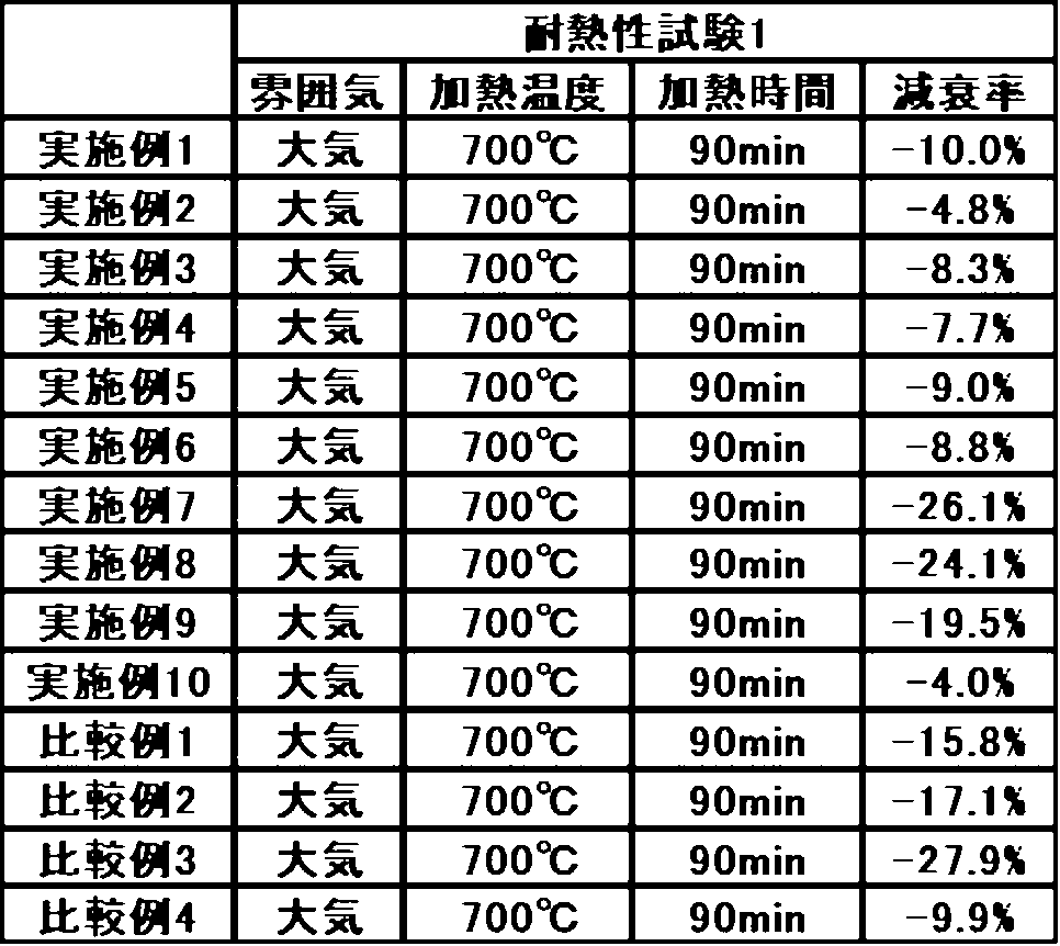
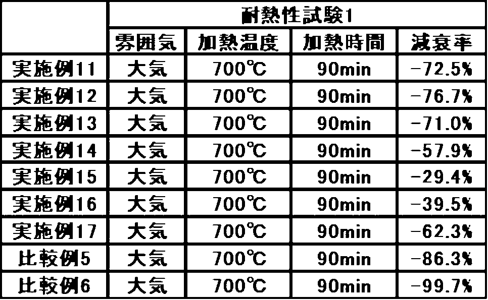
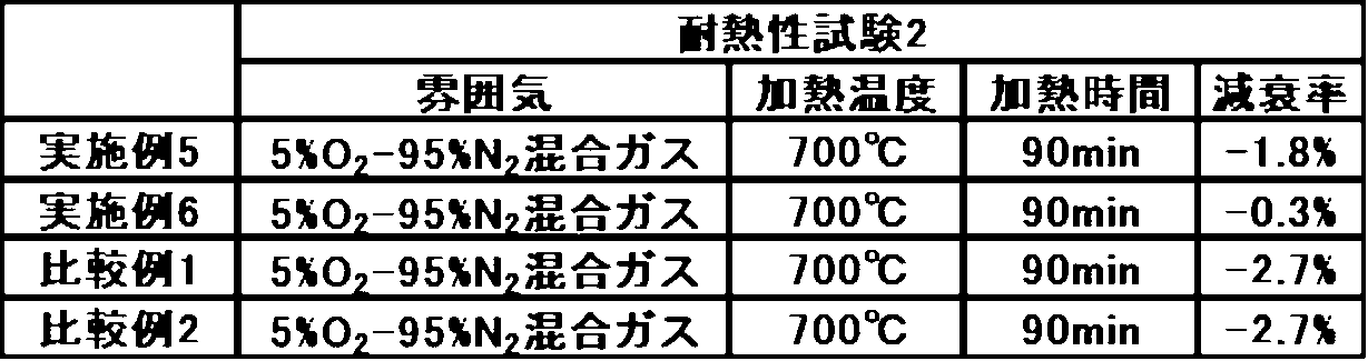
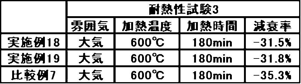
Claims (14)
- 炭素基材上に金属-炭素複合体被膜を有する被膜構造体の製造方法であって、
前記炭素基材上に金属化合物含有物を塗布する塗布工程と、
塗布された前記炭素基材を加熱することにより、前記炭素基材上に金属-炭素複合体被膜を形成する加熱工程と、
を有することを特徴とする被膜構造体の製造方法。 - 炭素基材上に金属-炭素複合体被膜を有する被膜構造体の製造方法であって、
前記炭素基材を金属化合物含有物に浸漬する浸漬工程と、
浸漬させた前記炭素基材を加熱することにより、前記炭素基材上に金属-炭素複合体被膜を形成する加熱工程と、
を有することを特徴とする被膜構造体の製造方法。 - 前記浸漬工程は、減圧下、又は真空下で、前記炭素基材に前記金属化合物含有物を含浸させることを特徴とする請求項2に記載の被膜構造体の製造方法。
- 前記塗布工程と又は前記浸漬工程と、前記加熱工程との間に、さらに乾燥工程を含むことを特徴とする請求項1~3の何れか1つに記載の被膜構造体の製造方法。
- 前記金属化合物含有物が、Ti、Nb、Mo、Hf、Ta、W、Zr、Siから選ばれる少なくとも1種の金属元素の化合物を含むことを特徴とする請求項1~3の何れか1つ記載の被膜構造体の製造方法。
- 前記金属化合物含有物中のTi、Nb、Mo、Hf、Ta、W、Zr、Siから選ばれる少なくとも1種の金属元素の化合物の含有量が、メタル換算で、0質量%超35質量%以下であることを特徴とする請求項5に記載の被膜構造体の製造方法。
- 前記金属化合物含有物が、Ta化合物を含むことを特徴とする請求項5に記載の被膜構造体の製造方法。
- 前記金属化合物含有物が、波長500nm~700nm領域の光透過率の最大値が70%T以上であることを特徴とする請求項1~3の何れか1つ記載の被膜構造体の製造方法。
- 前記金属化合物含有物が、動的光散乱法における前記金属化合物含有物中の粒子の粒子径(D50)が3000nm以下であることを特徴とする請求項1~3の何れか1つ記載の被膜構造体の製造方法。
- 前記金属化合物含有物が、pH6.5以上13.5以下であることを特徴とする請求項1~3の何れか1つ記載の被膜構造体の製造方法。
- 前記加熱工程は、加熱温度が1000℃以上3500℃以下であり、加熱時間が0.5時間以上2時間以下であることを特徴とする請求項1~3の何れか1つに記載の被膜構造体の製造方法。
- 前記加熱工程は、加熱温度が1400℃以上2000℃以下であることを特徴とする請求項11に記載の被膜構造体の製造方法。
- 炭素基材上に、金属-炭素複合体被膜が形成された被膜構造体であって、
前記金属-炭素複合体被膜は、金属化合物含有物が塗布、又は含浸された前記炭素基材を加熱することにより、形成されたことを特徴とする被膜構造体。 - 炭素基材上に形成される金属-炭素複合体被膜用の金属化合物含有物であって、
前記炭素基材と反応し、金属-炭素複合体被膜を形成することを特徴とする金属-炭素複合体被膜用の金属化合物含有物。
Priority Applications (5)
| Application Number | Priority Date | Filing Date | Title |
|---|---|---|---|
| KR1020257042336A KR20260030740A (ko) | 2023-06-29 | 2024-06-28 | 피막 구조체의 제조 방법, 및 피막 구조체 |
| CN202480042478.2A CN121399081A (zh) | 2023-06-29 | 2024-06-28 | 被膜结构体的制造方法及被膜结构体 |
| EP24832136.6A EP4737428A1 (en) | 2023-06-29 | 2024-06-28 | Coated structure manufacturing method, and coated structure |
| JP2024566757A JP7698155B2 (ja) | 2023-06-29 | 2024-06-28 | 被膜構造体の製造方法、及び被膜構造体 |
| JP2025097813A JP2025124903A (ja) | 2023-06-29 | 2025-06-11 | 被膜構造体の製造方法、及び被膜構造体 |
Applications Claiming Priority (4)
| Application Number | Priority Date | Filing Date | Title |
|---|---|---|---|
| JP2023107245 | 2023-06-29 | ||
| JP2023-107245 | 2023-06-29 | ||
| JP2023-141903 | 2023-09-01 | ||
| JP2023141903 | 2023-09-01 |
Publications (1)
| Publication Number | Publication Date |
|---|---|
| WO2025005279A1 true WO2025005279A1 (ja) | 2025-01-02 |
Family
ID=93938507
Family Applications (1)
| Application Number | Title | Priority Date | Filing Date |
|---|---|---|---|
| PCT/JP2024/023628 Ceased WO2025005279A1 (ja) | 2023-06-29 | 2024-06-28 | 被膜構造体の製造方法、及び被膜構造体 |
Country Status (6)
| Country | Link |
|---|---|
| EP (1) | EP4737428A1 (ja) |
| JP (2) | JP7698155B2 (ja) |
| KR (1) | KR20260030740A (ja) |
| CN (1) | CN121399081A (ja) |
| TW (1) | TW202502699A (ja) |
| WO (1) | WO2025005279A1 (ja) |
Cited By (1)
| Publication number | Priority date | Publication date | Assignee | Title |
|---|---|---|---|---|
| EP4600217A4 (en) * | 2022-10-03 | 2026-04-08 | Mitsui Kinzoku Company Ltd | PROCESS FOR THE PRODUCTION OF METALLIC CARBIDE, METALLIC CARBIDE POWDER AND INTERMEDIATE DISPERSED LIQUID OF METALLIC CARBIDE |
Citations (4)
| Publication number | Priority date | Publication date | Assignee | Title |
|---|---|---|---|---|
| JPS526714A (en) * | 1975-07-05 | 1977-01-19 | Tohoku Daigaku Kinzoku Zairyo | Manufacture of carbon products coated with silicon carbide |
| WO2004009515A1 (ja) | 2002-06-28 | 2004-01-29 | Ibiden Co., Ltd. | 炭素複合材料 |
| JP2017075075A (ja) * | 2015-10-16 | 2017-04-20 | 株式会社豊田中央研究所 | 耐熱黒鉛部材およびその製造方法 |
| WO2017082147A1 (ja) * | 2015-11-11 | 2017-05-18 | 日本カーボン株式会社 | 黒鉛基材上に形成された被膜及びその製造方法 |
-
2024
- 2024-06-28 TW TW113124368A patent/TW202502699A/zh unknown
- 2024-06-28 WO PCT/JP2024/023628 patent/WO2025005279A1/ja not_active Ceased
- 2024-06-28 JP JP2024566757A patent/JP7698155B2/ja active Active
- 2024-06-28 EP EP24832136.6A patent/EP4737428A1/en active Pending
- 2024-06-28 KR KR1020257042336A patent/KR20260030740A/ko active Pending
- 2024-06-28 CN CN202480042478.2A patent/CN121399081A/zh active Pending
-
2025
- 2025-06-11 JP JP2025097813A patent/JP2025124903A/ja active Pending
Patent Citations (4)
| Publication number | Priority date | Publication date | Assignee | Title |
|---|---|---|---|---|
| JPS526714A (en) * | 1975-07-05 | 1977-01-19 | Tohoku Daigaku Kinzoku Zairyo | Manufacture of carbon products coated with silicon carbide |
| WO2004009515A1 (ja) | 2002-06-28 | 2004-01-29 | Ibiden Co., Ltd. | 炭素複合材料 |
| JP2017075075A (ja) * | 2015-10-16 | 2017-04-20 | 株式会社豊田中央研究所 | 耐熱黒鉛部材およびその製造方法 |
| WO2017082147A1 (ja) * | 2015-11-11 | 2017-05-18 | 日本カーボン株式会社 | 黒鉛基材上に形成された被膜及びその製造方法 |
Cited By (1)
| Publication number | Priority date | Publication date | Assignee | Title |
|---|---|---|---|---|
| EP4600217A4 (en) * | 2022-10-03 | 2026-04-08 | Mitsui Kinzoku Company Ltd | PROCESS FOR THE PRODUCTION OF METALLIC CARBIDE, METALLIC CARBIDE POWDER AND INTERMEDIATE DISPERSED LIQUID OF METALLIC CARBIDE |
Also Published As
| Publication number | Publication date |
|---|---|
| TW202502699A (zh) | 2025-01-16 |
| KR20260030740A (ko) | 2026-03-06 |
| JP2025124903A (ja) | 2025-08-26 |
| CN121399081A (zh) | 2026-01-23 |
| EP4737428A1 (en) | 2026-05-06 |
| JPWO2025005279A1 (ja) | 2025-01-02 |
| JP7698155B2 (ja) | 2025-06-24 |
Similar Documents
| Publication | Publication Date | Title |
|---|---|---|
| JP4560089B2 (ja) | 次亜塩素酸塩を製造するための水溶液の電気分解に使用する電極 | |
| US5364522A (en) | Boride, carbide, nitride, oxynitride, and silicide infiltrated electrochemical ceramic films and coatings and the method of forming such | |
| JP2025124903A (ja) | 被膜構造体の製造方法、及び被膜構造体 | |
| US10995428B2 (en) | Graphene fiber and method of manufacturing the same | |
| DE4027999A1 (de) | Verfahren zur bildung eines keramischen films | |
| JP2023153202A (ja) | ニオブ酸リチウム溶液およびその製造方法 | |
| JP7544196B2 (ja) | 成膜用粉末の製造方法 | |
| US11649566B2 (en) | Graphene fiber and method of manufacturing the same | |
| JP7733255B2 (ja) | 被膜構造体の製造方法、及び被膜構造体 | |
| KR102866995B1 (ko) | 맥신-그래핀 복합체를 포함하는 발열체 및 이의 제조방법 | |
| JP7664464B2 (ja) | 金属化合物含有物 | |
| JP5523167B2 (ja) | セラミックス及び圧電/電歪素子 | |
| JP5302692B2 (ja) | コンデンサ材料およびその製造方法、ならびにその材料を含むコンデンサ、配線板および電子機器 | |
| JPH06321543A (ja) | 酸化ニオブゾル及びその製造方法 | |
| JP2008224447A (ja) | 酸化モリブデン薄膜の製造方法及び化学センサ | |
| Yang et al. | Vertically oriented titania nanotubes prepared by anodic oxidation on Si substrates | |
| US8524324B2 (en) | Complex oxide film and method for producing same, dielectric material including complex oxide film, piezoelectric material, capacitor, piezoelectric element, and electronic device | |
| JP2009073675A (ja) | 金属酸化物粉及びその製造方法 | |
| JP2009046343A (ja) | 高純度酸化モリブデン薄膜およびその製造方法 | |
| JP4276031B2 (ja) | チタン化合物被覆ニッケル粉末およびこれを用いた導電ペースト | |
| JP4734532B2 (ja) | 電子放出素子およびその製造方法 | |
| KR20250143078A (ko) | 하프늄산 화합물 함유물 및 그 제조 방법 | |
| JP2025006444A (ja) | 被膜構造体の製造方法、及び被膜構造体 | |
| Yordanov et al. | Preparation, phase and optical characterization of Sm2O3-ZrO2 coatings on glasses obtained by sol-gel technology using the Dip Coating method | |
| 时方晓 | Preparation of TiO2 and SiC films from their precursors using electrospraying |
Legal Events
| Date | Code | Title | Description |
|---|---|---|---|
| WWE | Wipo information: entry into national phase |
Ref document number: 2024566757 Country of ref document: JP |
|
| 121 | Ep: the epo has been informed by wipo that ep was designated in this application |
Ref document number: 24832136 Country of ref document: EP Kind code of ref document: A1 |
|
| WWE | Wipo information: entry into national phase |
Ref document number: 2024832136 Country of ref document: EP |
|
| NENP | Non-entry into the national phase |
Ref country code: DE |
|
| ENP | Entry into the national phase |
Ref document number: 2024832136 Country of ref document: EP Effective date: 20260129 |