WO2025005272A1 - 被膜構造体の製造方法、及び被膜構造体 - Google Patents
被膜構造体の製造方法、及び被膜構造体 Download PDFInfo
- Publication number
- WO2025005272A1 WO2025005272A1 PCT/JP2024/023617 JP2024023617W WO2025005272A1 WO 2025005272 A1 WO2025005272 A1 WO 2025005272A1 JP 2024023617 W JP2024023617 W JP 2024023617W WO 2025005272 A1 WO2025005272 A1 WO 2025005272A1
- Authority
- WO
- WIPO (PCT)
- Prior art keywords
- metal
- substrate
- coating
- reaction
- compound
- Prior art date
- Legal status (The legal status is an assumption and is not a legal conclusion. Google has not performed a legal analysis and makes no representation as to the accuracy of the status listed.)
- Ceased
Links
Images







Classifications
-
- B—PERFORMING OPERATIONS; TRANSPORTING
- B32—LAYERED PRODUCTS
- B32B—LAYERED PRODUCTS, i.e. PRODUCTS BUILT-UP OF STRATA OF FLAT OR NON-FLAT, e.g. CELLULAR OR HONEYCOMB, FORM
- B32B9/00—Layered products comprising a layer of a particular substance not covered by groups B32B11/00 - B32B29/00
-
- B—PERFORMING OPERATIONS; TRANSPORTING
- B32—LAYERED PRODUCTS
- B32B—LAYERED PRODUCTS, i.e. PRODUCTS BUILT-UP OF STRATA OF FLAT OR NON-FLAT, e.g. CELLULAR OR HONEYCOMB, FORM
- B32B9/00—Layered products comprising a layer of a particular substance not covered by groups B32B11/00 - B32B29/00
- B32B9/04—Layered products comprising a layer of a particular substance not covered by groups B32B11/00 - B32B29/00 comprising such particular substance as the main or only constituent of a layer, which is next to another layer of the same or of a different material
-
- C—CHEMISTRY; METALLURGY
- C01—INORGANIC CHEMISTRY
- C01B—NON-METALLIC ELEMENTS; COMPOUNDS THEREOF; METALLOIDS OR COMPOUNDS THEREOF NOT COVERED BY SUBCLASS C01C
- C01B32/00—Carbon; Compounds thereof
- C01B32/90—Carbides
- C01B32/914—Carbides of single elements
-
- C—CHEMISTRY; METALLURGY
- C04—CEMENTS; CONCRETE; ARTIFICIAL STONE; CERAMICS; REFRACTORIES
- C04B—LIME, MAGNESIA; SLAG; CEMENTS; COMPOSITIONS THEREOF, e.g. MORTARS, CONCRETE OR LIKE BUILDING MATERIALS; ARTIFICIAL STONE; CERAMICS; REFRACTORIES; TREATMENT OF NATURAL STONE
- C04B41/00—After-treatment of mortars, concrete, artificial stone or ceramics; Treatment of natural stone
- C04B41/80—After-treatment of mortars, concrete, artificial stone or ceramics; Treatment of natural stone of only ceramics
- C04B41/81—Coating or impregnation
- C04B41/85—Coating or impregnation with inorganic materials
- C04B41/87—Ceramics
-
- C—CHEMISTRY; METALLURGY
- C23—COATING METALLIC MATERIAL; COATING MATERIAL WITH METALLIC MATERIAL; CHEMICAL SURFACE TREATMENT; DIFFUSION TREATMENT OF METALLIC MATERIAL; COATING BY VACUUM EVAPORATION, BY SPUTTERING, BY ION IMPLANTATION OR BY CHEMICAL VAPOUR DEPOSITION, IN GENERAL; INHIBITING CORROSION OF METALLIC MATERIAL OR INCRUSTATION IN GENERAL
- C23C—COATING METALLIC MATERIAL; COATING MATERIAL WITH METALLIC MATERIAL; SURFACE TREATMENT OF METALLIC MATERIAL BY DIFFUSION INTO THE SURFACE, BY CHEMICAL CONVERSION OR SUBSTITUTION; COATING BY VACUUM EVAPORATION, BY SPUTTERING, BY ION IMPLANTATION OR BY CHEMICAL VAPOUR DEPOSITION, IN GENERAL
- C23C26/00—Coating not provided for in groups C23C2/00 - C23C24/00
Definitions
- the present invention relates to a method for producing a coated structure and a coated structure.
- carburizing, carbonitriding, and nitriding are used to harden the surface layer.
- Patent Document 1 discloses a method for hardening the surface of a steel workpiece by contacting the workpiece with a hardening gas in which carbon or nitrogen is combined with hydrogen in a treatment furnace under a vacuum atmosphere.
- the physical and/or chemical stability and other physical properties of the surface layer formed on the steel workpiece, i.e., the substrate surface, by carburizing, carbonitriding, and nitriding methods depended on the type and material of the substrate.
- the present invention provides a method for producing a coated structure, which is capable of forming a physically and chemically stable surface layer independent of the substrate, and which is capable of producing a coated structure having a uniform metal composite coating on the substrate, and a coated structure.
- the method for producing a coated structure of the present invention which has been made to solve the above-mentioned problems, is a method for producing a coated structure having a metal composite coating on a substrate, and is characterized by comprising: a step of applying or immersing a metal compound-containing material onto the substrate; and a reaction step of heating the substrate under reduced pressure or in vacuum while supplying a carbon source and/or a nitrogen source, thereby causing at least one reaction among a carbonization reaction, a carbonitriding reaction, and a nitriding reaction, to form a metal composite coating.
- the method for producing a coated structure of the present invention is independent of the substrate and can form a physically and chemically stable surface layer, thereby producing a coated structure having a uniform metal composite coating on a substrate.
- a "metal composite coating” may be a coating in which a metal element is present in a state bonded to other metal elements, metalloid elements, or nonmetallic elements.
- the metal element may be present in a mixed or dispersed state in the coating, rather than being bonded to other metal elements, metalloid elements, or nonmetallic elements.
- the metal compound include metal carbides, metal nitrides, metal carbonitrides, metal oxides, metal sulfides, and metal hydroxides, with metal carbides, metal nitrides, and metal carbonitrides being preferred, and multiple compounds may be present.
- the coated structure manufactured by the method for manufacturing a coated structure of the present invention has a metal composite coating on a substrate, and may be, for example, a substrate having a metal composite coating on at least one side (e.g., the surface) of the substrate, or a substrate having a metal composite coating on the entire peripheral surface of the substrate, and further includes a substrate having a metal composite coating on only a portion of one side of the substrate.
- the substrate is applied or immersed in a metal compound-containing material.
- the substrate used in the method for producing a coated structure of the present invention is characterized by containing at least one material selected from the group consisting of carbon, metal carbides, pure metals, alloys, metal oxides, and composite metal oxides.
- the substrate used in the method for producing a coated structure of the present invention may be any substrate containing at least one material selected from the group consisting of carbon, metal carbides, pure metals, alloys, metal oxides, and composite metal oxides, which will be described later.
- the carbon-containing substrate may be a substrate made of only carbon, a substrate whose main component is carbon and whose carbon content is 50% by mass or more, or a substrate having a multi-layer structure in which the outermost layer is made of only carbon or whose main component is carbon and whose carbon content is 50% by mass or more. It is particularly preferable that the carbon-containing substrate is a substrate made of only carbon.
- the size and shape of the carbon-containing substrate are not particularly limited as long as they are capable of being heated in the static furnace used in the process described below.
- Specific examples of carbon substrates include crucibles, furnace materials, electrodes, fibers, filtration devices, filters, protective tubes, heater tubes, burner nozzles, and fire-resistant jigs.
- Carbon materials that contain carbon as a substrate include fullerene, carbon nanotubes, carbon nanofibers, graphene, graphene oxide, carbon nanohorns, diamond, hyperdiamond, carbon fibers, etc.
- the carbon material may be made of only carbon or may be made of other materials containing carbon.
- the carbon material may have a uniform or heterogeneous structure.
- the uniform structure may be hollow or porous.
- the heterogeneous structure may be, for example, an island-in-the-sea structure, multi-layer structure, hollow, or porous.
- the carbon material may be in the form of a powder, plate, film, fiber, etc., and may be in the form of a molded product thereof, i.e., a mixture, a multi-layered product, a pressed powder product, a sintered product, a fiber bundle, a nonwoven material, or a woven material (plain weave, twill weave, satin weave, basket weave).
- the carbon material is preferably a fibrous material, and specific examples include metal fibers (steel fibers, etc.), ceramic fibers (metal oxide fibers, metal carbide fibers, metal nitride fibers, silicon carbide fibers, glass fibers, etc.), and polymer fibers (natural polymer fibers, polysaccharide fibers, cellulose fibers, artificial polymer fibers, resin fibers, carbon fibers, etc.).
- metal fibers steel fibers, etc.
- ceramic fibers metal oxide fibers, metal carbide fibers, metal nitride fibers, silicon carbide fibers, glass fibers, etc.
- polymer fibers natural polymer fibers, polysaccharide fibers, cellulose fibers, artificial polymer fibers, resin fibers, carbon fibers, etc.
- the substrate containing metal carbide may be a substrate made of only metal carbide, a substrate containing metal carbide as the main component with a metal carbide content of 50% by mass or more, or a substrate having a multi-layer structure with the outermost layer being made of only metal carbide or containing metal carbide as the main component with a metal carbide content of 50% by mass or more. It is particularly preferable that the substrate containing metal carbide is a substrate made of only metal carbide. Examples of metal carbides contained in the substrate include metal carbides such as tungsten carbide, molybdenum carbide, and tantalum carbide.
- the substrate containing pure metal may be a substrate made of only pure metal, a substrate mainly composed of pure metal with a pure metal content of 50% by mass or more, or a substrate having a multi-layer structure in which the outermost layer is made of only pure metal or mainly composed of pure metal with a pure metal content of 50% by mass or more. It is particularly preferable that the substrate containing pure metal is a substrate made of only pure metal. Pure metals contained in the substrate include pure metals such as Ti, V, Fe, Y, Zr, Cr, Ni, Mn, Co, Cu, Zn, and Pb.
- the substrate containing an alloy may be a substrate made of only an alloy, a substrate mainly made of an alloy with an alloy content of 50% by mass or more, or a substrate having a multi-layer structure in which the outermost layer is made of only an alloy or mainly made of an alloy with an alloy content of 50% by mass or more. It is particularly preferable that the substrate containing an alloy is a substrate made of only an alloy.
- alloys contained in the substrate include alloys containing at least one metal element selected from stainless steel (SUS), steel, brass, duralumin, titanium alloy, nickel alloy, aluminum alloy, copper alloy, zinc alloy, etc.
- the substrate material include SUS304 (JIS G4305 (2021)), SUS310S (JIS G4305 (2005)), SUS316 (JIS G4305 (2015)), SUS316L (JIS G4305 (2015) SUS316L), Ti (JIS H 4600 TP340C), and Inconel (SB-168UNSN06600 (2019ED)).
- the substrate containing a metal oxide may be a substrate made of only a metal oxide, a substrate mainly made of a metal oxide with a metal oxide content of 50% by mass or more, or a substrate having a multi-layer structure in which the outermost layer is made of only a metal oxide or mainly made of a metal oxide with a metal oxide content of 50% by mass or more. It is particularly preferable that the substrate containing a metal oxide is a substrate made of only a metal oxide. Examples of metal oxides contained in the substrate include titanium oxide, alumina, zirconia, magnesia, vanadia, nickel oxide, silica, and other metal oxides.
- the substrate containing a complex metal oxide may be a substrate made of only a complex metal oxide, a substrate mainly made of a complex metal oxide with a complex metal oxide content of 50% by mass or more, or a substrate having a multi-layer structure in which the outermost layer is made of only a complex metal oxide or a substrate mainly made of a complex metal oxide with a complex metal oxide content of 50% by mass or more. It is particularly preferable that the substrate containing a complex metal oxide is a substrate made of only a complex metal oxide.
- the complex metal oxide contained in the substrate may be a complex metal oxide containing at least one metal element selected from mullite, a silica-alumina mixture, an alumina-zirconia mixture, etc.
- the size and shape of the substrate are not particularly limited as long as they are capable of undergoing at least one of the carbonization reaction, carbonitriding reaction, and nitriding reaction described below, and may be plate-shaped, tubular, or cubic.
- Specific examples of substrates include crucibles, furnace materials, electrodes, fibers, filtration devices, filters, protective tubes, heater tubes, burner nozzles, and fire-resistant jigs.
- the metal compound-containing material used in the method for producing a coated structure of the present invention preferably contains a compound of at least one metal element selected from Ti, Nb, Mo, Hf, Ta, W, Zr, and Si.
- the metal compound-containing material may include a compound of at least one metal element selected from Ti, Nb, Mo, Hf, Ta, W, Zr, and Si.
- peroxo complex metal compounds e.g., peroxohydroxy acid complex metal compounds, peroxocitrate complex metal compounds, and peroxoammonium complex metal compounds
- metal element selected from Ti, Nb, Mo, Hf, Ta, W, Zr, and Si
- metal hydroxides e.g., ammonium oxalate complex metal compounds
- polyacids e.g., ammonium oxalate complex metal compounds
- the metal compound-containing material may contain a metal element, a semimetal element, or a nonmetal element other than at least one metal element selected from Ti, Nb, Mo, Hf, Ta, W, Zr, and Si.
- B, P, etc. may be mentioned.
- the metal compound-containing material is a peroxo complex metal compound, even if the substrate does not contain carbon, by heating the substrate to which the peroxo complex metal compound is applied, the metal element contained in the peroxo complex metal compound reacts with carbon to form a metal carbide. Also, if the metal compound-containing material is a hydroxy acid complex metal compound, the metal element contained in the hydroxy acid complex metal compound reacts with carbon to form a metal carbide.
- the content of the metal compound-containing material is preferably adjusted according to the metal element and the type of carbon-based substrate, and is more preferably more than 0 mass% and not more than 40 mass%, even more preferably 0.1 mass% to 30 mass%, particularly preferably 0.2 mass% to 30 mass%, and particularly preferably 0.3 mass% to 15 mass%.
- the metal compound-containing material contains multiple metal elements selected from Ti, Nb, Mo, Hf, Ta, W, Zr, and Si, it is preferable that the total value of each mass fraction is within the above-mentioned numerical range.
- the content of the metal compound-containing material may be calculated by diluting the metal compound-containing material appropriately with dilute hydrochloric acid as necessary, and measuring the mass fraction in metal equivalent using ICP emission spectrometry (AG-5110 manufactured by Agilent Technologies) in accordance with JIS K0116:2014.
- the content of the metal compound-containing material is preferably adjusted according to the type of metal element and carbon-based substrate, and is more preferably more than 0 mass% and not more than 35 mass%, even more preferably 0.03 mass% to 25 mass%, particularly preferably 0.06 mass% to 25 mass%, and particularly preferably 0.1 mass% to 15 mass%.
- metal compound-containing material contains multiple metal elements selected from Ti, Nb, Mo, Hf, Ta, W, Zr, and Si, it is preferable that the total mass fraction of each metal element is within the above-mentioned numerical range.
- metal conversion means Ti conversion, Nb conversion, Mo conversion, Hf conversion, Ta conversion, W conversion, Zr conversion, and Si conversion.
- the metal compound-containing material used in the method for producing a coated structure of the present invention more preferably contains a compound of at least one metal element selected from the group consisting of Nb, Hf and Ta.
- the metal compound-containing material may include a compound of at least one metal element selected from Nb, Hf, and Ta.
- Specific examples of the metal compound-containing material include peroxo complex metal compounds (e.g., peroxohydroxy acid complex metal compounds, peroxocitrate complex metal compounds, and peroxoammonium complex metal compounds) containing at least one metal element selected from Nb, Hf, and Ta, metal hydroxides, hydroxy acid complex metal compounds (e.g., ammonium oxalate complex metal compounds), and polyacids, but are not limited to these compounds.
- the metal compound-containing material used in the method for producing a coated structure of the present invention may also contain a resin. If the metal compound-containing material contains a resin, the resin is uniformly compatible with the metal compound and acts to adhere to the substrate, thereby improving film-forming properties and adhesion to the substrate. This is preferable.
- the resins contained in the metal compound-containing material include polyolefin compounds, polyvinyl compounds, etc.
- the metal compound-containing material used in the method for producing a coated structure of the present invention may also contain a carbon material. If the metal compound-containing material contains a carbon material, the carbon material becomes a carbon component during carbonization, which is preferable in that carbonization is improved.
- the metal compound-containing material used in the method for producing a coated structure of the present invention may be a solution, a sol, or a gel.
- the metal compound-containing material is one that contains a metal compound, and more specifically, one that is liquefied by the application of shear stress.
- the metal compound-containing material may include one that is normally in a liquid, sol, gel, or semi-solid state, and may be applied to a substrate.
- the metal compound-containing material used in the method for producing a coated structure of the present invention is a solution, since it can be easily applied to a substrate.
- the gel may be one that has a viscosity of 200 mPa ⁇ s or more at 25°C as measured by the rotating cylinder method.
- the metal compound-containing material used in the method for producing a coated structure of the present invention is characterized in that the maximum light transmittance in the wavelength region of 500 nm to 700 nm is 70%T or more, and the particle diameter (D50) of the particles in the metal compound-containing material as measured by a dynamic light scattering method is 3000 nm or less.
- the metal compound-containing material used in the method for producing a coated structure of the present invention has a maximum light transmittance of 70%T or more in the wavelength region of 500 nm to 700 nm, and the particle diameter (D50) of the particles in the metal compound-containing material is 3000 nm or less as measured by a dynamic light scattering method, which is preferable from the viewpoints of high dispersibility, excellent uniformity of the components in the liquid, and stability over time.
- the metal compound-containing material used in the method for producing a coated structure of the present invention preferably has a maximum light transmittance of 70%T or more in the wavelength region of 500nm to 700nm, because this provides high dispersion and excellent uniformity of the components in the liquid. It is more preferable that the maximum light transmittance of the wavelength region of 500nm to 700nm is 72%T or more, even more preferable that it is 74%T or more, particularly preferable that it is 76%T or more, particularly preferable that it is 78%T or more, and even more particularly preferable that it is 80%T or more.
- the light transmittance of the wavelength region of 500nm to 700nm may be 80%T. Note that, due to measurement errors, etc., the measured value of the light transmittance may exceed 100%T, but since the theoretical upper limit is 100%T, if the measured value exceeds 100%T, it is considered to be 100%T.
- the light transmittance in the wavelength range of 500 nm to 700 nm is measured using a spectrophotometer according to the following light transmittance measurement conditions for the metal compound-containing material used in the manufacturing method of the coating structure of the present invention.
- Light transmittance measurement conditions Measurement device: UV-Vis-NIR spectrophotometer UH4150 (manufactured by Hitachi High-Tech Science Corporation) Measurement mode: Wavelength scan Data mode: %T (transmittance) Measurement wavelength range: 200 nm to 2000 nm Scan speed: 600 nm/min Sampling interval: 2 nm
- the light transmittance in the wavelength region of 500 nm to 700 nm is determined by placing 3 g of the metal compound-containing material containing a Si compound adjusted to room temperature (25°C) in a measurement cell (light path length 1 cm) and measuring the ultraviolet-visible absorption spectrum (UV-Vis absorption spectrum) in accordance with the following light transmittance measurement conditions (including Si) in accordance with JIS K 0115, 2004 "General rules for spectrophotometric analysis methods.”
- Measurement device U-2900 spectrophotometer (Hitachi High-Tech Corporation) Measurement mode: Wavelength scan Data mode: %T (transmittance) Measurement wavelength range: 200 nm to 1000 nm Scan speed: 200 nm/min Sampling interval: 1 nm Cell length: 10 mm ⁇ Measuring cell: Disposable square cell for particle size (manufactured by Otsuka Electronics Co., Ltd.)
- the particle diameter (D50) of the particles in the metal compound-containing material used in the method for producing a coated structure of the present invention is 3000 nm or less, and more preferably 2000 nm or less, and may be 1000 nm or less, 500 nm or less, 400 nm or less, or 300 nm or less.
- the particle diameter (D50) is preferably 0.1 nm or more, more preferably 0.5 nm or more, even more preferably 0.7 nm or more, and particularly preferably 1 nm or more.
- the particle diameter (D50) is 0.6 nm or more and 200 nm or less.
- the dynamic light scattering method is a method in which a solution such as a suspension is irradiated with light such as a laser beam to measure the light scattering intensity from a group of particles undergoing Brownian motion, and the particle size and distribution are obtained from the temporal variation of the intensity.
- the particle size distribution is evaluated using a zeta potential, particle size, and molecular weight measurement system (ELSZ-2000ZS, manufactured by Otsuka Electronics Co., Ltd.) in accordance with JIS Z 8828:2019 "Particle size analysis - dynamic light scattering method".
- the measurement sample is diluted 1000 times with pure water, and the measurement sample is filtered with a filter with a pore size of 11 ⁇ m to remove dust and the like from the measurement sample immediately before measurement, and ultrasonic treatment is performed for 3 minutes with an ultrasonic cleaner (VS-100III, manufactured by AS ONE Co., Ltd.).
- the liquid temperature of the measurement sample is adjusted to 25°C.
- the particle diameter (D50) refers to the median diameter (D50), which is the particle diameter that shows the 50% integrated value of the integrated distribution curve.
- the metal compound-containing material used in the method for producing a coated structure of the present invention has a pH of more than 7, and examples of the solvent include water, alcohol, ketone, ester, etc., and two or more types of solvents may be mixed, and it is preferable that the solvent contains water.
- the pH of the metal compound-containing material is preferably more than 7, since the solubility is good.
- the pH of the metal compound-containing material is more preferably 7.5 or more, and even more preferably 8.0 or more.
- the pH of the metal compound-containing material may be 8.5 or more, 9.0 or more, 9.5 or more, 10.0 or more, 10.5 or more, or 11.0 or more.
- the pH of the metal compound-containing material is preferably 13.5 or less, more preferably 13.0 or less, and even more preferably 12.5 or less. Furthermore, it is preferable that the metal compound-containing material contains water as a solvent, from the viewpoint of reducing the environmental load.
- the pH of the metal compound-containing material used in the method for producing a coating structure of the present invention is measured by immersing the electrode (HORIBA: Standard ToupH electrode 9615S-10D) of a pH meter (HORIBA: Glass electrode type hydrogen ion concentration indicator D-51) in the metal compound-containing material and confirming that the liquid temperature has stabilized at 25°C.
- HORIBA Standard ToupH electrode 9615S-10D
- HORIBA Glass electrode type hydrogen ion concentration indicator D-51
- the metal compound-containing material is applied or immersed on the substrate.
- Specific methods for applying a metal compound-containing material onto a substrate include spraying, inkjet, dispenser, nozzle coating, slit coating, die coating, roll coating, spin coating, blade coating, knife coating, wire bar coating, screen printing, brush coating, etc.
- the method of immersing the substrate in a material containing metal compounds involves immersing the substrate in a container filled with the material containing metal compounds, thereby impregnating the substrate with the material containing metal compounds.
- the immersion time in this step is preferably 6 minutes to 1 hour, and more preferably 12 minutes to 54 minutes.
- the step of immersing the substrate in a material containing metal compounds may be carried out at room temperature, or may be heated and then cooled to room temperature.
- the immersion step in the method for producing a coated structure of the present invention is preferable in that immersing the substrate in a substance containing a metal compound under reduced pressure or in a vacuum makes it easier for the substrate to be impregnated with the substance containing a metal compound, and the immersion time in this step can be shortened.
- a container filled with the metal compound-containing material in which the substrate is immersed is placed in a pressure reducing device and placed under reduced pressure or vacuum, which makes it easier for the metal compound-containing material to be impregnated into the substrate.
- the degree of vacuum in the pressure reducing device is preferably 0.05 MPa or less, more preferably 0.04 MPa or less, even more preferably 0.03 MPa or less, and particularly preferably 0.02 MPa or less.
- the immersion time in the immersion step under reduced pressure or vacuum is preferably 0.1 hour or more and 0.5 hour or less, and more preferably 0.2 hour or more and 0.4 hour or less.
- a metal composite coating is formed only on one side of the substrate, for example only on the surface, only the surface of the substrate is immersed in the metal compound-containing material.
- a metal composite coating is formed on the entire peripheral surface of the substrate, the entire peripheral surface of the substrate is immersed in the metal compound-containing material.
- the substrate is heated under reduced pressure or vacuum while a carbon source and/or nitrogen source is being supplied, thereby causing at least one of a carbonization reaction, a carbonitriding reaction, and a nitriding reaction to occur, forming a metal composite coating.
- the carbonization reaction, carbonitriding reaction, or nitriding reaction is a reaction that includes the following multiple processes:
- the substrate coated or immersed in the metal compound-containing material is placed in a vacuum carbonitriding furnace (e.g., model VCQ400, manufactured by Oriental Engineering Co., Ltd.) and placed under reduced pressure or vacuum.
- a vacuum carbonitriding furnace e.g., model VCQ400, manufactured by Oriental Engineering Co., Ltd.
- the substrate is heated under reduced pressure or vacuum at a preheating temperature for a specified preheating time.
- the substrate is further heated at a soaking temperature for a specified soaking time.
- a carbon source and/or nitrogen source is supplied from the outside, and the substrate is heated at a carburizing temperature, a carbonitriding temperature, or a nitriding temperature for a specified carburizing time, a carbonitriding time, or a nitriding time.
- the method for producing a coated structure of the present invention is characterized in that the reaction step is a carbonization reaction, and the carbon source is either one containing an unsaturated hydrocarbon and an inert component, or a saturated hydrocarbon.
- the reaction step in the method for producing a coated structure of the present invention is a carbonization reaction
- the carbon source supplied into the vacuum carbonitriding furnace is either one containing an unsaturated hydrocarbon and an inert component, or a saturated hydrocarbon, in that hydrogen produced by decomposition of the unsaturated hydrocarbon or the saturated hydrocarbon removes oxygen in the applied metal compound-containing material and promotes the metal carbide production reaction.
- Unsaturated hydrocarbons include acetylene, etc.
- Inert components include argon, nitrogen, etc.
- the method for producing a coated structure of the present invention is characterized in that the reaction step is a carbonitriding reaction or a nitriding reaction, and the nitrogen source contains ammonia and an inert component.
- the reaction step in the method for producing a coated structure of the present invention is a carbonitriding reaction or a nitriding reaction
- the nitrogen source supplied to the vacuum carbonitriding furnace contains ammonia and an inert component, in order to promote the reaction for producing a metal carbonitride or a metal nitride.
- the inert component is as described above.
- the reaction step is a carbonitriding reaction
- the carbon source and nitrogen source supplied to the vacuum carbonitriding furnace contain either all of an unsaturated hydrocarbon, a nitriding agent, and an inert component, or all of a saturated hydrocarbon and a nitriding agent, in that this makes it easier to control the carbide-forming reaction or the nitride-forming reaction.
- nitriding agents include ammonia and nitrogen.
- saturated hydrocarbons include methane, propane, butane, etc. The unsaturated hydrocarbons and inert components are as described above.
- a carburizing temperature of 800°C or higher and 1150°C or lower is preferable because the carburizing reaction of the coating proceeds sufficiently and the coating quality is stable.
- a carburizing temperature of 850°C or higher and 1100°C or lower is more preferable, and a carburizing temperature of 900°C or higher and 1050°C or lower is even more preferable.
- a carburizing time of 3 minutes or more and 2 hours or less is preferable because it can supply carbon suitable for generating metal carbides.
- a carburizing time of 6 minutes or more and 1 hour or less is more preferable, and a carburizing time of 6 minutes or more and 15 minutes or less is even more preferable.
- the carbonitriding temperature is preferably 700°C or higher and 1050°C or lower, as this allows the carbonitriding reaction of the coating to proceed sufficiently and stabilizes the coating quality.
- the carbonitriding temperature is more preferably 750°C or higher and 1000°C or lower, and even more preferably 800°C or higher and 900°C or lower.
- a carbonitriding time of 3 minutes or more and 2 hours or less is preferable because it can provide a sufficient supply of carbon and nitrogen necessary for the production of metal carbonitride.
- a carbonitriding time of 18 minutes or more and 1 hour or less is more preferable, and a time of 18 minutes or more and 30 minutes or less is even more preferable.
- the nitriding temperature is preferably 500°C or higher and 1000°C or lower, as this allows the nitriding reaction of the coating to proceed sufficiently and stabilizes the coating quality.
- the nitriding temperature is more preferably 500°C or higher and 900°C or lower, and even more preferably 750°C or higher and 850°C or lower.
- a nitriding time of 3 minutes or more and 2 hours or less is preferable because it can provide a sufficient amount of nitrogen necessary for the production of metal nitrides.
- a nitriding time of 6 minutes or more and 1 hour or less is more preferable, and a nitriding time of 6 minutes or more and 15 minutes or less is even more preferable.
- the reaction step is performed at a heating temperature of 500° C. or higher and 1150° C. or lower.
- a heating temperature of 500° C. or higher and 1150° C. or lower is preferable in that the carburization reaction, carbonitriding reaction, or nitriding reaction of the coating proceeds sufficiently and the coating quality is stabilized.
- the heating temperature is the carburization temperature, carbonitriding temperature, or nitriding temperature described above.
- the method for producing a coated structure of the present invention is also characterized in that the heating time is from 0.05 hours to 10 hours.
- a heating time of 0.05 hours or more and 10 hours or less is preferable in that carbon and/or nitrogen necessary for forming metal carbide, metal carbonitride, or metal nitride can be sufficiently supplied.
- the heating time is the carburizing time, the carbonitriding time, or the nitriding time.
- the degree of vacuum inside the vacuum carbonitriding furnace is preferably 1,330 Pa or less, and more preferably 133 Pa or less.
- the above-described method for producing a coated structure of the present invention can be used to produce a coated structure having a metal composite coating formed on a substrate.
- the method for producing a coated structure of the present invention may further include a drying step between the step of applying or immersing the metal compound-containing material on the substrate and the reaction step in the method for producing a coated structure of the present invention described above.
- the substrate coated or soaked in the metal compound-containing material is placed in a static furnace and dried at 100°C for 1 hour, which is preferable in that excess impurities such as moisture can be removed.
- the drying temperature in the drying process is more preferably 110°C or higher and 400°C or lower, even more preferably 120°C or higher and 300°C or lower, and particularly preferably 130°C or higher and 200°C or lower.
- the drying time in the drying process is preferably 0.2 hours or more and 3 hours or less, more preferably 0.3 hours or more and 2 hours or less, and even more preferably 0.4 hours or more and 1 hour or less.
- the method for producing a coated structure of the present invention may further include a baking step under vacuum between the drying step and the reaction step in the method for producing a coated structure of the present invention described above.
- the substrate coated or soaked in the dried metal compound-containing material is preferably fired at a firing temperature of 750°C for 1 hour, which removes oxygen from the metal compound.
- the firing temperature is preferably 750°C or higher and 1000°C or lower, as this allows for efficient oxygen removal. It is more preferable for the firing temperature to be 800°C or higher and 950°C or lower, and even more preferable for the firing temperature to be 850°C or higher and 900°C or lower.
- a baking time of 1 hour or more and 3 hours or less is preferable because oxygen can be removed efficiently.
- a baking time of 0.5 hours or more and 1.5 hours or less is even more preferable.
- the method for producing a coated structure of the present invention is characterized in that the step of applying or immersing a metal compound-containing substance on a substrate according to the above-mentioned method for producing a coated structure of the present invention and the reaction step are repeated multiple times.
- a metal composite coating is formed multiple times on the substrate, and a metal composite coating that is more physically and chemically stable can be formed.
- the metal composite coating formed by the method for producing a coated structure of the present invention contains a compound of at least one metal element selected from Ti, Nb, Mo, Hf, Ta, W, Zr, and Si, this is preferable in that the durability of the coated substrate is improved.
- Compounds contained in the metal composite coating include metal carbides, metal nitrides, metal carbonitrides, metal oxides, metal sulfides, and metal hydroxides of at least one metal element selected from Ti, Nb, Mo, Hf, Ta, W, Zr, and Si.
- Metal carbides, metal nitrides, and metal carbonitrides are preferred, and a plurality of compounds may be present.
- the metal composite coating formed by the method for producing a coated structure of the present invention contains a compound of at least one metal element selected from Nb, Hf, and Ta, it is more preferable in that the durability of the coated substrate is further improved.
- the metal composite coating formed by the method for producing a coating structure of the present invention contains at least one metal carbide selected from Ti carbide, Nb carbide, Mo carbide, Hf carbide, Ta carbide, W carbide, Zr carbide, and Si carbide, it is particularly preferable in that the coating structure in which the metal composite coating is formed on the substrate is physically and chemically stable.
- the coating structure of the present invention being physically stable means, for example, physical stability in heat resistance tests, and indicates thermal stability at higher temperatures.
- physical stability can be further improved in hardness tests, instrumented indentation tests, or scratch tests.
- the coating structure of the present invention being chemically stable means that it is chemically stable against, for example, hydrochloric acid, sulfuric acid, nitric acid, phosphoric acid, hydrofluoric acid, sodium chloride, acetic acid, oxalic acid, ammonia water, sodium hydroxide, potassium hydroxide, water vapor, hydrogen sulfide gas, ammonia gas, hydrogen gas, fluorine gas, chlorine gas, nitrogen oxide gas (NOx), or sulfur oxide gas (SOx).
- hydrochloric acid sulfuric acid, nitric acid, phosphoric acid, hydrofluoric acid, sodium chloride, acetic acid, oxalic acid, ammonia water, sodium hydroxide, potassium hydroxide, water vapor, hydrogen sulfide gas, ammonia gas, hydrogen gas, fluorine gas, chlorine gas, nitrogen oxide gas (NOx), or sulfur oxide gas (SOx).
- the metal composite coating formed on the substrate manufactured by the method for manufacturing the coating structure of the present invention described above can be confirmed to contain a metal compound from the peaks of the X-ray diffraction pattern obtained by performing X-ray diffraction measurement according to the following X-ray diffraction measurement conditions and X-ray diffraction analysis conditions.
- X-ray diffraction measurement conditions ⁇ Apparatus: MiniFlex II (manufactured by Rigaku Corporation) Measurement range (2 ⁇ ): 5 to 90° ⁇ Sampling width: 0.02° Scan speed: 2.0°/min ⁇ X-ray: CuK ⁇ ray ⁇ Voltage: 30 kV Current: 15mA Divergence slit: 1.25° Scattering slit: 1.25° ⁇ Receiving slit: 0.3 mm
- the thickness of the metal composite coating formed on the substrate manufactured by the method for manufacturing a coated structure of the present invention is 500 nm or less, this is preferable in that cracks in the film and peeling of the film itself are unlikely to occur.
- the thickness of the metal composite coating may be 300 nm or less, or may be 100 nm or less. This is because if cracks occur in the metal composite coating, the substrate is oxidized and is likely to be released as an oxide, and the elements in the substrate are likely to decrease.
- the thickness of the metal composite coating is 1 nm or more, this is preferable in that the substrate can be sufficiently protected.
- the thickness of the metal composite coating may be 10 nm or more.
- the coated structure of the present invention is a coated structure having a metal composite coating on a substrate,
- the metal composite coating is characterized in that it is formed by heating a substrate coated or immersed in a metal compound-containing substance under reduced pressure or vacuum while supplying a carbon source and/or a nitrogen source, thereby causing at least one reaction among a carbonization reaction, a carbonitriding reaction, and a nitriding reaction.
- the coating structure of the present invention has a uniform metal composite coating on a substrate as a surface layer that is physically and chemically stable, independent of the substrate.
- the coated structure of the present invention is a coated structure having a metal-carbon composite coating on a substrate, characterized in that the metal-carbon composite coating has a D band/G band peak area ratio of 0.5 or more and 2.0 or less in Raman spectroscopy.
- the coated structure of the present invention has a metal-carbon composite coating on a substrate, and when the metal-carbon composite coating has a D band/G band peak area ratio of 0.5 to 2.0 in Raman spectroscopy, it is preferable in that a physically and chemically stable surface layer can be formed and a coating having a uniform composition can be formed.
- the coating structure of the present invention preferably has a D band/G band peak area ratio of 0.8 to 2.0, more preferably 0.8 to 1.5, and particularly preferably 1.1 to 1.3.
- Raman spectroscopy is a spectroscopy method for evaluating the chemical structure and bonding state of carbon materials.
- peaks are usually observed at 1300 cm -1 to 1400 cm -1 and 1550 cm -1 to 1650 cm -1 .
- G band In highly crystalline graphite, a single peak is observed at 1550 cm -1 to 1650 cm -1 , and this peak is called "G band”.
- D band As the crystallinity decreases (the crystal structure defects increase), a peak appears at 1300 cm -1 to 1400 cm -1 , and this peak is called "D band”.
- the D band/G band peak area ratio is an index of the amount of defects in the crystal structure of the carbon material.
- the D band/G band peak intensity ratio is also called the R value.
- the metal-carbon composite coating formed on the substrate can be confirmed to be a metal carbide from the peak (half width) of the Raman spectrum obtained by measuring it according to the Raman spectroscopy measurement conditions and Raman spectroscopy measurement conditions below.
- Raman spectroscopy measurement conditions ⁇ Apparatus: Invia Qontor (manufactured by Renishaw Co., Ltd.) ⁇ Light source: 532nm (RL532-08 150mW) ⁇ Objective lens: 20x ⁇ Grating: 1800mm/L Irradiation time: 5 to 10 seconds; Accumulation count: 1; Slit width: 65 ⁇ m Laser power: 1% ⁇ Use Livetrac function ⁇ Measure 20 x 20 square map (10 ⁇ m intervals in both X and Y directions)
- Raman spectroscopy analysis conditions According to the above-mentioned Raman spectroscopy measurement conditions, the Raman spectrum obtained is subjected to baseline correction (intelligence polynomial: degree 6) and average spectrum processing in WiRE5.5 manufactured by Renishaw Ltd., and normalization processing is performed so that the maximum value at 1550 cm -1 to 1650 cm -1 in the obtained average spectrum becomes 1. Next, using Igor Pro ver. 8.04 manufactured by WaveMetrics, multipeak Fitting 2 is applied to the normalized spectrum, and the initial peak is set with reference to the description in Table 1 in Chapter 8, Section 4 of Raman Spectroscopic Data Analysis Case Studies (Technical Information Association Co., Ltd.). The peak adopts a Gaussian distribution or a Lorentzian distribution.
- Each peak obtained by the above procedure is classified into D band and G band based on the peak position, the sum of the peak areas of each band is calculated, and the sum of the D band peak areas divided by the sum of the G band peak areas is defined as the D band/G band peak area ratio.
- the coated structure of the present invention is a coated structure having a metal-carbon composite coating on a substrate, characterized in that a D band/G band peak area ratio of the metal-carbon composite coating in Raman spectroscopy is 0.5 or more and 2.0 or less, and a standard deviation of the D band/G band peak area ratio is 0.1 or more and 0.35 or less.
- the coated structure of the present invention has a metal-carbon composite coating on a substrate, and when the metal-carbon composite coating has a D band/G band peak area ratio of 0.5 to 2.0 in Raman spectroscopy and a standard deviation of the D band/G band peak area ratio of 0.1 to 0.35, it is preferable in that a physically and chemically stable surface layer can be formed and a coating having a uniform composition can be formed.
- the coating structure of the present invention preferably has a D band/G band peak area ratio of 0.8 to 2.0, more preferably 0.8 to 1.5, and particularly preferably 1.1 to 1.3.
- the D band/G band peak area ratio is as described above, and will not be described in detail.
- the standard deviation of the D band/G band peak area ratio of the coating structure of the present invention is more preferably 0.2 to 0.33, and even more preferably 0.23 to 0.30.
- the standard deviation of the D band/G band peak area ratio can be calculated based on the above-mentioned D band/G band peak area ratio.
- the Raman spectrum measured at any 400 measurement points can be calculated from the D band/G band peak area ratio calculated for the 400 points according to the above-mentioned Raman spectroscopy analysis conditions.
- the coating structure of the present invention is preferable in that the thickness of the metal-carbon composite coating formed on the substrate is 300 nm or less, since this makes it difficult for cracks to form in the film or for the film itself to peel off.
- X to Y (X and Y are any numbers) is used, unless otherwise specified, it includes the meaning of “X or more and Y or less”, as well as “preferably greater than X” or “preferably smaller than Y”. Furthermore, when “X or more” (X is any number) or “Y or less” (Y is any number), it also includes the meaning of "preferably greater than X” or "preferably less than Y”.
- the method for producing a coated structure of the present invention is independent of the substrate and can form a physically and chemically stable surface layer, making it possible to produce a coated structure having a uniform metal composite coating on a substrate.
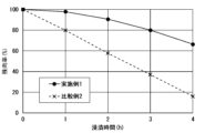
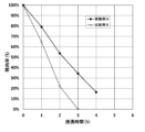
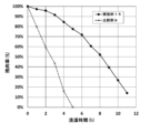
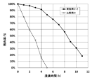
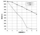
- 1 is a graph showing the measurement results of corrosion resistance test 1 for Example 1 and Comparative Example 2.
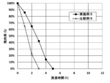
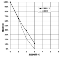
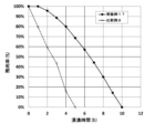
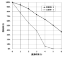
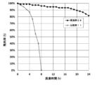
- 1 is a graph showing the measurement results of corrosion resistance test 1 for Example 5 and Comparative Example 5.
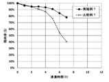
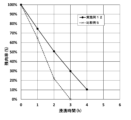
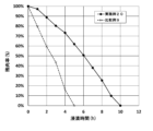
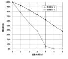
- 1 is a graph showing the measurement results of corrosion resistance test 1 for Example 6 and Comparative Example 6.
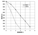
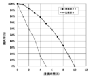
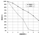
- 1 is a graph showing the measurement results of corrosion resistance test 1 for Example 7 and Comparative Example 7.
- 1 is a graph showing the measurement results of corrosion resistance test 1 for Example 8 and Comparative Example 8.
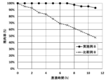
- 1 is a graph showing the measurement results of corrosion resistance test 1 for Example 9 and Comparative Example 5.
- 1 is a graph showing the measurement results of corrosion resistance test 1 for Example 10 and Comparative Example 5.
- 1 is a graph showing the measurement results of corrosion resistance test 1 for Example 11 and Comparative Example 5.
- 1 is a graph showing the measurement results of corrosion resistance test 1 for Example 12 and Comparative Example 5.
- 1 is a graph showing the measurement results of corrosion resistance test 1 for Example 13 and Comparative Example 5.
- 1 is a graph showing the measurement results of corrosion resistance test 1 for Example 14 and Comparative Example 5.
- 1 is a graph showing the measurement results of corrosion resistance test 2 for Example 15 and Comparative Example 9.
- 1 is a graph showing the measurement results of corrosion resistance test 2 for Example 16 and Comparative Example 9.
- 1 is a graph showing the measurement results of corrosion resistance test 2 for Example 17 and Comparative Example 9.
- 1 is a graph showing the measurement results of corrosion resistance test 2 for Example 18 and Comparative Example 9.
- 1 is a graph showing the measurement results of corrosion resistance test 2 for Example 19 and Comparative Example 9.
- 1 is a graph showing the measurement results of corrosion resistance test 2 for Example 20 and Comparative Example 9. 1 is a graph showing the measurement results of corrosion resistance test 2 for Example 21 and Comparative Example 9. 1 is a graph showing the measurement results of corrosion resistance test 2 for Example 22 and Comparative Example 9. 1 is a graph showing the measurement results of corrosion resistance test 2 for Example 23 and Comparative Example 10. 1 is a graph showing the measurement results of corrosion resistance test 2 for Example 24 and Comparative Example 10. 13 is a graph showing the measurement results of corrosion resistance test 2 for Example 25 and Comparative Example 10. 1 is a graph showing the measurement results of corrosion resistance test 2 for Example 26 and Comparative Example 10. 1 is a graph showing the measurement results of corrosion resistance test 2 for Example 27 and Comparative Example 9.
- 1 is a graph showing the measurement results of corrosion resistance test 2 for Example 28 and Comparative Example 11.
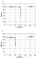
- 1A is a graph showing the measurement results of a heat resistance test of a coating structure according to Example 2
- FIG. 1B is a graph showing the measurement results of a heat resistance test of a tubular metal substrate according to Comparative Example 3.
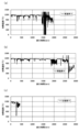
- Graph (a) shows the measurement results of a heat resistance test of the coated structure of Example 3
- graph (b) shows the measurement results of a heat resistance test of the coated structure of Example 4
- graph (c) shows the measurement results of a heat resistance test of a tubular metal substrate of Comparative Example 4.
- the coating structure according to the embodiment of the present invention will be further described below with reference to the following examples.
- the present invention is not limited to the following examples.
- the JIS standards for the metal substrate materials used in each example are as described above.
- Example 1 A tantalic acid compound-containing liquid was applied to the entire surface of a metal substrate (SUS304) (length x width x thickness: 30 mm x 35 mm x 1.5 mm) using a brush (the amount of application was 0.015 g). Next, the metal substrate coated with the tantalic acid compound-containing liquid was naturally dried. Next, the naturally dried metal substrate coated with the tantalic acid compound-containing liquid was placed in an electric furnace and fired at 350°C for 30 minutes. After firing, the substrate was air-cooled to room temperature. At that time, a tantalic acid compound-dispersed coating film was formed on the metal substrate.
- SUS304 metal substrate
- the naturally dried metal substrate coated with the tantalic acid compound-containing liquid was placed in an electric furnace and fired at 350°C for 30 minutes. After firing, the substrate was air-cooled to room temperature. At that time, a tantalic acid compound-dispersed coating film was formed on the metal substrate.
- the metal-based substrate on which the tantalic acid compound-dispersed coating film was formed was placed in a vacuum carbonitriding furnace (manufactured by Oriental Engineering Co., Ltd., model: VCQ400), and heated in a vacuum at a preheating temperature of 850°C for 60 minutes, and then heated for a soaking time of 1020°C for 60 minutes.
- a vacuum carbonitriding furnace manufactured by Oriental Engineering Co., Ltd., model: VCQ400
- a carburizing treatment was performed for 35 minutes at a carburizing temperature of 1020°C to carburize the tantalic acid compound-dispersed coating film and the metal-based substrate (hereinafter referred to as the "carburizing time").
- the gas pressure of the acetylene gas (C 2 H 2 ) was 1066.576 Pa.
- a diffusion treatment was performed for 75 minutes at a diffusion temperature of 1020°C to diffuse the carbon that had penetrated into the tantalic acid compound-dispersed coating film and the metal-based substrate (hereinafter referred to as the "diffusion time").
- the total time of the "carburizing time” and the “diffusion time” is referred to as the “carburizing treatment time” in Table 1.
- the tantalum in the tantalic acid compound dispersed coating film was subjected to a carbonization reaction.
- the tantalic acid compound-containing liquid used in Example 1 was obtained as follows.
- tantalum hydroxide (Ta 2 O 5 concentration 66 mass %) manufactured by Mitsui Mining & Smelting Co., Ltd. was dissolved in 120 g of 55 mass % hydrofluoric acid aqueous solution, and 849 mL of ion-exchanged water was added to obtain an aqueous tantalum fluoride solution (Ta 2 O 5 concentration 8.2 mass %).
- This reaction liquid was a slurry of a tantalic acid compound hydrate, in other words, a slurry of a tantalum-containing precipitate.
- this reaction liquid was decanted using a centrifuge and washed until the amount of liberated fluoride ions was 100 mg/L or less, to obtain a tantalum-containing precipitate from which the fluoride ions had been removed.
- Ammonia water was used as the washing liquid.
- the tantalum-containing precipitate from which the fluoride ions had been removed was diluted with pure water to obtain a tantalum-containing precipitate slurry.
- a portion of this tantalum-containing precipitate slurry was dried at 110° C. for 24 hours and then fired at 1,000° C. for 4 hours to produce Ta2O5 , and the concentration of Ta2O5 in the tantalum-containing precipitate slurry was calculated from its weight.
- the tantalum-containing precipitate slurry diluted with pure water, 5 mass% dimethylamine as an organic nitrogen compound, and pure water were mixed so that the tantalum concentration of the final mixture was 5 mass% in terms of Ta2O5 and the weight ratio of Ta2O5 /organic nitrogen compound was 1.0, thereby obtaining the tantalic acid compound-containing liquid used in Example 1.
- the pH of the tantalic acid compound-containing liquid used in Example 1 was 12.0.
- Example 2 the tantalic acid compound-containing liquid was applied to the surface of a SUS protective tube (SUS304) (tube diameter x length x thickness: ⁇ 25 mm x 300 mm x 1.0 mm) for a thermocouple temperature sensor [K type] in a molten metal furnace using a brush (the amount of application was 0.1439 g).
- SUS304 tube diameter x length x thickness: ⁇ 25 mm x 300 mm x 1.0 mm
- K type thermocouple temperature sensor
- the SUS protective tube on which the tantalic acid compound dispersion coating film was formed was placed in a vacuum carbonitriding furnace (manufactured by Oriental Engineering Co., Ltd., model: VCQ400), and heated in a vacuum at a preheating temperature of 850°C for 60 minutes, and then heated for a soaking time of 1020°C for 60 minutes.
- a vacuum carbonitriding furnace manufactured by Oriental Engineering Co., Ltd., model: VCQ400
- a carburization treatment was performed for 35 minutes at a carburization temperature of 1020°C to carburize the tantalic acid compound dispersion coating film and the SUS protective tube.
- the gas pressure of the acetylene gas (C 2 H 2 ) was 1066.576 Pa.
- a diffusion treatment was performed for 75 minutes at a diffusion temperature of 1020°C to diffuse the carbon that had penetrated into the tantalic acid compound dispersion coating film and the SUS protective tube under vacuum.
- the tantalum in the tantalic acid compound dispersed coating film was subjected to a carbonization reaction, thereby carrying out a carbonization reaction.
- Example 2 a coating structure according to Example 2 was obtained.
- the tantalic acid compound-containing liquid used in Example 2 was obtained in the same manner as the tantalic acid compound-containing liquid used in Example 1.
- Example 3 In Example 3, a coating structure according to Example 3 was obtained by carrying out a manufacturing method similar to that of Example 2, except that the substrate was a SUS protective tube (SUS316) (tube diameter x length x thickness: ⁇ 21.7 mm x 300 mm x 2.8 mm) for a thermocouple temperature sensor [K type] in a molten metal furnace (the coating amount was 0.125 g).
- SUS316 SUS protective tube
- K type thermocouple temperature sensor
- Example 4 a coated structure according to Example 4 was obtained by carrying out the same manufacturing method as in Example 2, except that (i) the substrate was a SUS protective tube (SUS316) (tube diameter ⁇ length ⁇ thickness: ⁇ 21.7 mm ⁇ 300 mm ⁇ 2.8 mm) for a thermocouple temperature sensor [K type] in a molten metal furnace, (ii) the carburization treatment was carried out twice, and (iii) the carburization treatment time per carburization treatment was 110 minutes (the coating amount was 0.125 g).
- SUS316 SUS protective tube
- K type thermocouple temperature sensor
- Example 4 a first carbonization reaction was carried out as described above, and a second carbonization reaction was carried out on the metal-based substrate obtained after the first carbonization reaction in the same manner as the first carbonization reaction, thereby forming a second tantalic acid compound dispersion coating film on the metal-based substrate after the first carbonization reaction. That is, in Example 4, the carburization treatment was carried out twice.
- Example 5 a coating structure according to Example 5 was obtained by carrying out the same manufacturing method as in Example 1, except that (i) the substrate was a metal substrate (SUS304) (length ⁇ width ⁇ thickness: 20 mm ⁇ 20 mm ⁇ 1.0 mm) and (ii) the carburization temperature was 1070° C. (the coating amount was 0.016 g).
- the substrate was a metal substrate (SUS304) (length ⁇ width ⁇ thickness: 20 mm ⁇ 20 mm ⁇ 1.0 mm) and (ii) the carburization temperature was 1070° C. (the coating amount was 0.016 g).
- Example 6 a coating structure according to Example 6 was obtained by carrying out the same manufacturing method as in Example 1, except that (i) the substrate was a metal substrate (SUS310S) (length ⁇ width ⁇ thickness: 20 mm ⁇ 20 mm ⁇ 1.0 mm) and (ii) the carburization temperature was 1070° C. (the coating amount was 0.016 g).
- the substrate was a metal substrate (SUS310S) (length ⁇ width ⁇ thickness: 20 mm ⁇ 20 mm ⁇ 1.0 mm) and (ii) the carburization temperature was 1070° C. (the coating amount was 0.016 g).
- Example 7 a coating structure according to Example 7 was obtained by carrying out the same manufacturing method as in Example 1, except that (i) the substrate was a metal substrate (Inconel: registered trademark) (length x width x thickness: 20 mm x 20 mm x 1.0 mm) and (ii) the carburization temperature was 1070°C (the coating amount was 0.016 g).
- the substrate was a metal substrate (Inconel: registered trademark) (length x width x thickness: 20 mm x 20 mm x 1.0 mm) and (ii) the carburization temperature was 1070°C (the coating amount was 0.016 g).
- Example 8 In Example 8, the same manufacturing method as in Example 1 was carried out, except that (i) the substrate was a metal substrate (made of titanium) (length x width x thickness: 20 mm x 20 mm x 1.0 mm) and (ii) the carburization temperature was 1070°C, to obtain a coated structure according to Example 1 (the coating amount was 0.016 g).
- Example 9 a coating structure according to Example 9 was obtained by carrying out the same manufacturing method as in Example 1, except that (i) the substrate was a metal substrate (SUS304) (length ⁇ width ⁇ thickness: 20 mm ⁇ 20 mm ⁇ 1.0 mm), (ii) the niobium compound-containing liquid was applied to the entire surface of the substrate using a brush (the amount applied was 0.0135 g), (iii) the carburization temperature was 1070° C., and (iv) the carburization treatment time was 57 minutes (the carburization time was 18 minutes, and the diffusion time was 39 minutes).
- SUS304 metal substrate
- the niobium compound-containing liquid was applied to the entire surface of the substrate using a brush (the amount applied was 0.0135 g)
- the carburization temperature was 1070° C.
- the carburization treatment time was 57 minutes (the carburization time was 18 minutes, and the diffusion time was 39 minutes).
- the niobium compound-containing liquid used in Example 9 was obtained as follows.
- This reaction liquid was a slurry of a niobium acid compound hydrate, in other words, a slurry of a niobium-containing precipitate.
- reaction solution was decanted using a centrifuge and washed until the amount of liberated fluoride ions was 100 mg/L or less to obtain a niobium-containing precipitate from which the fluoride ions had been removed.
- Ammonia water was used as the washing solution.
- the niobium-containing precipitate from which the fluoride ions had been removed was diluted with pure water to obtain a slurry.
- a part of this niobium-containing precipitate slurry was dried at 110° C. for 24 hours and then fired at 1000° C. for 4 hours to produce Nb 2 O 5 , and the concentration of Nb 2 O 5 contained in the niobium-containing precipitate slurry was calculated from its weight.
- Example 10 a coated structure according to Example 10 was obtained by carrying out the same manufacturing method as in Example 1, except that (i) the substrate was a metal substrate (SUS304) (length ⁇ width ⁇ thickness: 20 mm ⁇ 20 mm ⁇ 1.0 mm), (ii) the titanic acid compound-containing liquid was applied to the entire surface of the substrate using a brush (the amount applied was 0.01 g), (iii) the carburization temperature was 1070° C., and (iv) the carburization treatment time was 57 minutes (the carburization time was 18 minutes, and the diffusion time was 39 minutes).
- SUS304 metal substrate
- the titanic acid compound-containing liquid was applied to the entire surface of the substrate using a brush (the amount applied was 0.01 g)
- the carburization temperature was 1070° C.
- the carburization treatment time was 57 minutes (the carburization time was 18 minutes, and the diffusion time was 39 minutes).
- the titanate compound-containing liquid used in Example 10 was obtained as follows.
- titanyl sulfate manufactured by Teika Corporation, TiO2 concentration 33.3 mass%, sulfuric acid concentration 51.1 mass% was added to 66.7 g of ion-exchanged water, and the mixture was allowed to stand at 90°C or higher for 1 hour to dissolve, thereby obtaining an aqueous titanyl sulfate solution (titanium concentration (TiO2 equivalent) 11 mass%, sulfuric acid 17 mass%, pH 1 or less).
- This titanyl sulfate aqueous solution was added to 100 g of 50% by mass dimethylamine (6.4 moles of amine per mole of sulfuric acid in the titanyl sulfate aqueous solution) over a period of less than one minute. The mixture was then stirred for 15 minutes to obtain a neutralized reaction liquid (pH 12).
- This neutralized reaction liquid was a slurry of titanium-containing material, in other words, a slurry of titanium-containing precipitates.
- this neutralized reaction liquid was decanted using a centrifuge and washed until the sulfuric acid in the supernatant was 100 mg/L or less, obtaining a titanium-containing precipitate from which the sulfuric acid had been removed.
- ammonia water was used as the washing liquid.
- TiO2 concentration in the titanium-containing precipitate was calculated from the mass of TiO2.
- the TiO2 concentration was 11.0 mass%.
- Example 11 a coated structure according to Example 11 was obtained by carrying out the same production method as in Example 1, except that (i) the substrate was a metal substrate (SUS304) (length ⁇ width ⁇ thickness: 20 mm ⁇ 20 mm ⁇ 1.0 mm), (ii) the zirconium oxide compound-containing liquid was applied to the entire surface of the substrate using a brush (the amount applied was 0.02 g), (iii) the carburization temperature was 1070° C., and (iv) the carburization treatment time was 57 minutes (the carburization time was 18 minutes, and the diffusion time was 39 minutes).
- SUS304 metal substrate
- the zirconium oxide compound-containing liquid was applied to the entire surface of the substrate using a brush (the amount applied was 0.02 g)
- the carburization temperature was 1070° C.
- the carburization treatment time was 57 minutes (the carburization time was 18 minutes, and the diffusion time was 39 minutes).
- the zirconium oxide compound-containing liquid used in Example 11 was obtained as follows.
- This reaction liquid was a slurry of a zirconium oxide compound hydrate, in other words, a slurry of a zirconium-containing precipitate.
- the reaction liquid was decanted using a centrifuge and washed until the conductivity was 500 ⁇ S/cm or less, yielding a zirconium-containing precipitate from which the sulfur had been removed. Ammonia water was used as the washing liquid.
- the zirconium-containing precipitate from which the sulfur content was removed was diluted with pure water to obtain a zirconium-containing precipitate slurry from which the sulfur content was removed.
- a part of the zirconium-containing precipitate slurry from which the sulfur content was removed was dried at 110°C for 24 hours, and then fired at 1,000°C for 4 hours to generate ZrO2 , and the ZrO2 concentration contained in the zirconium-containing precipitate slurry from which the sulfur content was removed was calculated from the weight of the ZrO2.
- the pH of the zirconium acid compound-containing liquid used in Example 11 was 13.7.
- Example 12 a coated structure according to Example 12 was obtained by carrying out the same manufacturing method as in Example 1, except that (i) the substrate was a metal substrate (SUS304) (length ⁇ width ⁇ thickness: 20 mm ⁇ 20 mm ⁇ 1.0 mm), (ii) the hafnium acid compound-containing liquid was applied to the entire surface of the substrate using a brush (the amount applied was 0.014 g), (iii) the carburization temperature was 1070° C., and (iv) the carburization treatment time was 57 minutes (the carburization time was 18 minutes, and the diffusion time was 39 minutes).
- SUS304 metal substrate
- the hafnium acid compound-containing liquid was applied to the entire surface of the substrate using a brush (the amount applied was 0.014 g)
- the carburization temperature was 1070° C.
- the carburization treatment time was 57 minutes (the carburization time was 18 minutes, and the diffusion time was 39 minutes).
- the hafnium acid compound-containing liquid used in Example 12 was obtained as follows.
- hafnium oxide (98% purity, powder, manufactured by Kojundo Kagaku Kenkyusho Co., Ltd.)
- 105.1g of 55% by mass hydrofluoric acid and 796.9g of pure water heat to 80°C using a water bath, and dissolve by stirring for 24 hours to obtain a hafnium compound hydrofluoric acid solution.
- the neutralized reaction liquid was then decanted using a centrifuge to recover the precipitate (including hafnium hydroxide).
- the recovered precipitate was mixed with 200 g of 25% by mass ammonia water to form a slurry, which was then decanted again to recover the precipitate. This decantation and precipitate (including hafnium hydroxide) recovery process was repeated three times.
- Example 13 a coated structure according to Example 13 was obtained by carrying out the same production method as in Example 1, except that (i) the substrate was a metal substrate (SUS304) (length ⁇ width ⁇ thickness: 20 mm ⁇ 20 mm ⁇ 1.0 mm), (ii) the tungstic acid compound-containing liquid was applied to the entire surface of the substrate using a brush (the amount applied was 0.0165 g), (iii) the carburization temperature was 1070° C., and (iv) the carburization treatment time was 57 minutes (the carburization time was 18 minutes, and the diffusion time was 39 minutes).
- SUS304 metal substrate
- the tungstic acid compound-containing liquid was applied to the entire surface of the substrate using a brush (the amount applied was 0.0165 g)
- the carburization temperature was 1070° C.
- the carburization treatment time was 57 minutes (the carburization time was 18 minutes, and the diffusion time was 39 minutes).
- the tungsten acid compound-containing liquid used in Example 13 was obtained as follows.
- reaction liquid 100 g of tungsten trioxide was dissolved in 200 g of 55 mass % aqueous sulfuric acid solution, and ion-exchanged water was added to obtain an aqueous tungsten sulfate solution containing 100 g/L of tungsten calculated as WO3 .
- This reaction liquid was a slurry of a tungsten acid compound hydrate, in other words, a slurry of a tungsten-containing precipitate.
- reaction liquid was decanted using a centrifuge and washed until the conductivity was 500 ⁇ S/cm or less, yielding a tungsten-containing precipitate from which the sulfur had been removed.
- Ammonia water was used as the washing liquid.
- the tungsten-containing precipitate from which the sulfur content was removed was diluted with pure water to obtain a tungsten-containing precipitate slurry from which the sulfur content was removed.
- a part of the tungsten-containing precipitate slurry from which the sulfur content was removed was dried at 110°C for 24 hours, and then fired at 1,000°C for 4 hours to produce WO3 , and the WO3 concentration contained in the tungsten-containing precipitate slurry from which the sulfur content was removed was calculated from the weight of the WO3.
- the tungsten-containing precipitate slurry from which the sulfur content had been removed and diluted with pure water was mixed with 2% by mass of methylamine and pure water so that the tungsten concentration of the final mixture was 10% by mass in terms of WO3 , and the mixture was stirred and held for 1 hour while maintaining the liquid temperature at room temperature (25°C), thereby obtaining the tungsten acid compound-containing liquid used in Example 13.
- the pH of the tungsten acid compound-containing liquid used in Example 13 was 8.2.
- Example 14 a coated structure according to Example 14 was obtained by carrying out the same production method as in Example 1, except that (i) the substrate was a metal substrate (SUS304) (length ⁇ width ⁇ thickness: 20 mm ⁇ 20 mm ⁇ 1.0 mm), (ii) the molybdic acid compound-containing liquid was applied to the entire surface of the substrate using a brush (the amount applied was 0.017 g), (iii) the carburization temperature was 1070° C., and (iv) the carburization treatment time was 57 minutes (the carburization time was 18 minutes, and the diffusion time was 39 minutes).
- SUS304 metal substrate
- the molybdic acid compound-containing liquid was applied to the entire surface of the substrate using a brush (the amount applied was 0.017 g)
- the carburization temperature was 1070° C.
- the carburization treatment time was 57 minutes (the carburization time was 18 minutes, and the diffusion time was 39 minutes).
- the molybdic acid compound-containing liquid used in Example 14 was obtained as follows.
- reaction liquid 100 g of molybdenum trioxide was dissolved in 200 g of a 55 mass% aqueous sulfuric acid solution, and ion-exchanged water was added to obtain an aqueous molybdenum sulfate solution containing 100 g/L of molybdenum calculated as MoO3 .
- This reaction liquid was a slurry of a molybdic acid compound hydrate, in other words, a slurry of a molybdenum-containing precipitate.
- reaction liquid was decanted using a centrifuge and washed until the conductivity was 500 ⁇ S/cm or less, yielding a molybdenum-containing precipitate from which the sulfur had been removed.
- Ammonia water was used as the washing liquid.
- the molybdenum-containing precipitate from which the sulfur content was removed was diluted with pure water to obtain a molybdenum-containing precipitate slurry from which the sulfur content was removed.
- a part of the molybdenum-containing precipitate slurry from which the sulfur content was removed was dried at 110°C for 24 hours and then fired at 1,000°C for 4 hours to produce MoO3 , and the MoO3 concentration contained in the molybdenum-containing precipitate slurry from which the sulfur content was removed was calculated from the weight of the MoO3.
- the molybdenum-containing precipitate slurry from which the sulfur content had been removed and diluted with pure water was mixed with 2% by mass of methylamine and pure water so that the molybdenum concentration of the final mixture was 10% by mass in terms of MoO3 , and the mixture was stirred and held for 1 hour while maintaining the liquid temperature at room temperature (25°C), thereby obtaining the molybdic acid compound-containing liquid used in Example 14.
- the pH of the molybdic acid compound-containing liquid used in Example 14 was 9.7.
- Example 15 The coated structure of Example 15 was obtained by carrying out the same manufacturing method as in Example 6.
- Example 16 a coated structure according to Example 16 was obtained by carrying out the same manufacturing method as in Example 1, except that (i) the substrate was a metal substrate (SUS310S) (length ⁇ width ⁇ thickness: 20 mm ⁇ 20 mm ⁇ 1.0 mm), (ii) the niobate compound-containing liquid was applied to the entire surface of the substrate using a brush (the amount applied was 0.0135 g), and (iii) the carburization temperature was 1070° C.
- SUS310S metal substrate
- the niobate compound-containing liquid was applied to the entire surface of the substrate using a brush (the amount applied was 0.0135 g)
- the carburization temperature was 1070° C.
- Example 16 The niobic acid compound-containing liquid used in Example 16 was obtained in the same manner as the niobic acid compound-containing liquid used in Example 9.
- Example 17 a coated structure according to Example 17 was obtained by carrying out the same manufacturing method as in Example 1, except that (i) the substrate was a metal substrate (SUS310S) (length x width x thickness: 20 mm x 20 mm x 1.0 mm), (ii) the titanic acid compound-containing liquid was applied to the entire surface of the substrate using a brush (the amount applied was 0.01 g), and (iii) the carburization temperature was 1070°C.
- SUS310S metal substrate
- the titanic acid compound-containing liquid was applied to the entire surface of the substrate using a brush (the amount applied was 0.01 g)
- the carburization temperature was 1070°C.
- the titanate compound-containing liquid used in Example 17 was obtained in the same manner as the titanate compound-containing liquid used in Example 10.
- Example 18 a coated structure according to Example 18 was obtained by carrying out the same production method as in Example 1, except that (i) the substrate was a metal substrate (SUS310S) (length ⁇ width ⁇ thickness: 20 mm ⁇ 20 mm ⁇ 1.0 mm), (ii) the zirconium oxide compound-containing liquid was applied to the entire surface of the substrate using a brush (the amount of application was 0.02 g), and (iii) the carburization temperature was 1070° C.
- SUS310S metal substrate
- the zirconium oxide compound-containing liquid was applied to the entire surface of the substrate using a brush (the amount of application was 0.02 g)
- the carburization temperature was 1070° C.
- the zirconium oxide compound-containing liquid used in Example 18 was obtained in the same manner as the zirconium oxide compound-containing liquid used in Example 11.
- Example 19 a coated structure according to Example 19 was obtained by carrying out the same manufacturing method as in Example 1, except that (i) the substrate was a metal substrate (SUS310S) (length ⁇ width ⁇ thickness: 20 mm ⁇ 20 mm ⁇ 1.0 mm), (ii) the hafnium acid compound-containing liquid was applied to the entire surface of the substrate using a brush (the amount applied was 0.0139 g), and (iii) the carburization temperature was 1070° C.
- SUS310S metal substrate
- the hafnium acid compound-containing liquid was applied to the entire surface of the substrate using a brush (the amount applied was 0.0139 g)
- the carburization temperature was 1070° C.
- the hafnium acid compound-containing liquid used in Example 19 was obtained in the same manner as the hafnium acid compound-containing liquid used in Example 12.
- Example 20 a coated structure according to Example 20 was obtained by carrying out the same production method as in Example 1, except that (i) the substrate was a metal substrate (SUS310S) (length ⁇ width ⁇ thickness: 20 mm ⁇ 20 mm ⁇ 1.0 mm), (ii) the tungstic acid compound-containing liquid was applied to the entire surface of the substrate using a brush (the amount of application was 0.0165 g), and (iii) the carburization temperature was 1070° C.
- SUS310S metal substrate
- the tungstic acid compound-containing liquid was applied to the entire surface of the substrate using a brush (the amount of application was 0.0165 g)
- the carburization temperature was 1070° C.
- Example 20 The tungsten acid compound-containing liquid used in Example 20 was obtained in the same manner as the tungsten acid compound used in Example 13.
- Example 21 a coated structure according to Example 21 was obtained by carrying out the same production method as in Example 1, except that (i) the substrate was a metal substrate (SUS310S) (length ⁇ width ⁇ thickness: 20 mm ⁇ 20 mm ⁇ 1.0 mm), (ii) the entire surface of the substrate was coated with a molybdic acid compound-containing liquid using a brush (the coating amount was 0.0173 g), and (iii) the carburization temperature was 1070° C.
- SUS310S metal substrate
- the coating amount was 0.0173 g
- the carburization temperature was 1070° C.
- the molybdic acid compound-containing liquid used in Example 21 was obtained in the same manner as the molybdic acid compound-containing liquid used in Example 14.
- Example 22 a coated structure according to Example 22 was obtained by carrying out the same production method as in Example 1, except that (i) the substrate was a metal substrate (SUS310S) (length ⁇ width ⁇ thickness: 20 mm ⁇ 20 mm ⁇ 1.0 mm), (ii) the silicic acid compound-containing liquid was applied to the entire surface of the substrate using a brush (the amount applied was 0.0169 g), and (iii) the carburization temperature was 1070° C.
- SUS310S metal substrate
- the silicic acid compound-containing liquid was applied to the entire surface of the substrate using a brush (the amount applied was 0.0169 g)
- the carburization temperature was 1070° C.
- the silicate compound-containing liquid used in Example 22 was obtained as follows.
- Example 23 The coated structure of Example 23 was obtained by carrying out the same manufacturing method as in Example 5.
- Example 24 a coated structure according to Example 24 was obtained by carrying out the same manufacturing method as in Example 1, except that (i) the substrate was a metal substrate (SUS304) (length ⁇ width ⁇ thickness: 20 mm ⁇ 20 mm ⁇ 1.0 mm), (ii) a mixed liquid of a tantalic acid compound-containing liquid and a titanic acid compound-containing liquid was applied to the entire surface of the substrate using a brush (the amount applied was 0.013 g), and (iii) the carburization temperature was 1070° C.
- SUS304 metal substrate
- a mixed liquid of a tantalic acid compound-containing liquid and a titanic acid compound-containing liquid was applied to the entire surface of the substrate using a brush (the amount applied was 0.013 g)
- the carburization temperature was 1070° C.
- the mixed liquid of tantalic acid compound-containing liquid and titanic acid compound-containing liquid used in Example 24 was prepared by mixing a tantalic acid compound-containing liquid obtained in the same manner as the tantalic acid compound-containing liquid used in Example 1 and a titanic acid compound-containing liquid obtained in the same manner as the titanic acid compound-containing liquid used in Example 10, each adjusted to 50% by mass.
- Example 25 a coated structure according to Example 25 was obtained by carrying out the same manufacturing method as in Example 1, except that (i) the substrate was a metal substrate (SUS304) (length ⁇ width ⁇ thickness: 20 mm ⁇ 20 mm ⁇ 1.0 mm), (ii) a mixed liquid of a tantalic acid compound-containing liquid and a tungsten oxide-containing liquid was applied to the entire surface of the substrate using a brush (the amount applied was 0.016 g), and (iii) the carburization temperature was 1070° C.
- SUS304 metal substrate
- a mixed liquid of a tantalic acid compound-containing liquid and a tungsten oxide-containing liquid was applied to the entire surface of the substrate using a brush (the amount applied was 0.016 g)
- the carburization temperature was 1070° C.
- the mixed liquid of tantalic acid compound-containing liquid and tungstic acid compound-containing liquid used in Example 25 was prepared by mixing a tantalic acid compound-containing liquid obtained in the same manner as the tantalic acid compound-containing liquid used in Example 1 and a tungstic acid compound-containing liquid obtained in the same manner as the tungstic acid compound-containing liquid used in Example 13, each adjusted to 50% by mass.
- Example 26 a coated structure according to Example 26 was obtained by carrying out the same manufacturing method as in Example 1, except that (i) the substrate was a metal substrate (SUS304) (length x width x thickness: 20 mm x 20 mm x 1.0 mm), (ii) the carburizing temperature was 1070°C, (iii) the carburizing treatment was performed twice, and (iv) the carburizing treatment time per carburizing treatment was 110 minutes (the coating amount was 0.016 g).
- SUS304 metal substrate
- the carburizing temperature was 1070°C
- the carburizing treatment was performed twice
- the carburizing treatment time per carburizing treatment was 110 minutes (the coating amount was 0.016 g).
- Example 27 a coated structure according to Example 27 was obtained by carrying out the same manufacturing method as in Example 1, except that (i) the substrate was a metal substrate (SUS310S) (length x width x thickness: 20 mm x 20 mm x 1.0 mm), (ii) the carburizing temperature was 1070°C, (iii) the carburizing treatment was performed twice, and (iv) the carburizing treatment time per carburizing treatment was 110 minutes (the coating amount was 0.016 g).
- SUS310S metal substrate
- the carburizing temperature was 1070°C
- the carburizing treatment was performed twice
- the carburizing treatment time per carburizing treatment was 110 minutes (the coating amount was 0.016 g).
- Example 28 a coated structure according to Example 28 was obtained by carrying out the same manufacturing method as in Example 1, except that (i) the substrate was a metal substrate (Inconel: registered trademark) (length x width x thickness dimensions: 20 mm x 20 mm x 1.0 mm), (ii) the carburizing temperature was 1070°C, (iii) the carburizing treatment was performed twice, and (iv) the carburizing treatment time per carburizing treatment was 110 minutes (the coating amount was 0.016 g).
- the substrate was a metal substrate (Inconel: registered trademark) (length x width x thickness dimensions: 20 mm x 20 mm x 1.0 mm)
- the carburizing temperature was 1070°C
- the carburizing treatment was performed twice
- the carburizing treatment time per carburizing treatment was 110 minutes (the coating amount was 0.016 g).
- Example 29 The coated structure of Example 29 was obtained by carrying out the same manufacturing method as in Example 5.
- Comparative Example 1 is a carbon-based substrate, specifically a graphite extrusion material (length x width x thickness: 50 mm x 50 mm x 3 mm). Note that no coating film such as a tantalic acid compound dispersion coating film was formed on the substrate in Comparative Example 1.
- Comparative Example 2 is a metal-based substrate, specifically, the metal-based substrate (SUS304) (length ⁇ width ⁇ thickness: 30 mm ⁇ 35 mm ⁇ 1.5 mm) used in Example 1. Note that no coating film such as a tantalic acid compound dispersed coating film was formed on the substrate in Comparative Example 2.
- SUS304 the metal-based substrate
- no coating film such as a tantalic acid compound dispersed coating film was formed on the substrate in Comparative Example 2.
- Comparative Example 3 is a tubular metal-based substrate, specifically a SUS protective tube (tube diameter ⁇ length ⁇ thickness: ⁇ 25 mm ⁇ 300 mm ⁇ 1.0 mm) for a thermocouple sensor [K type] in a molten metal furnace used in Example 2. Note that no coating film such as a tantalic acid compound dispersion coating film was formed on the substrate in Comparative Example 3.
- Comparative Example 4 is a tubular metal-based substrate, specifically a SUS protective tube (SUS316) (tube diameter ⁇ length ⁇ thickness: ⁇ 21.7 mm ⁇ 300 mm ⁇ 2.8 mm) for a thermocouple temperature sensor [K type] in the molten metal furnace used in Examples 3 and 4. Note that no coating film such as a tantalic acid compound dispersion coating film was formed on the substrate in Comparative Example 4.
- SUS316 SUS protective tube
- K type thermocouple temperature sensor
- Comparative Example 5 is a metal-based substrate, specifically, the metal-based substrate (SUS304) (length ⁇ width ⁇ thickness: 20 mm ⁇ 20 mm ⁇ 1.0 mm) used in Examples 5, 9 to 14, 22, and 23. Note that no coating film such as a tantalic acid compound dispersed coating film was formed on the substrate in Comparative Example 5.
- SUS304 the metal-based substrate
- no coating film such as a tantalic acid compound dispersed coating film was formed on the substrate in Comparative Example 5.
- Comparative Example 6 is a metal-based substrate, specifically, the metal-based substrate (SUS304) (length ⁇ width ⁇ thickness: 20 mm ⁇ 20 mm ⁇ 1.0 mm) used in Examples 6 and 15 to 21. Note that no coating film such as a tantalic acid compound dispersed coating film was formed on the substrate in Comparative Example 6.
- Comparative Example 7 is a metal-based substrate, specifically, the metal-based substrate (Inconel: registered trademark) (length x width x thickness: 20 mm x 20 mm x 1.0 mm) used in Example 7. Note that no coating film such as a tantalic acid compound dispersed coating film was formed on the substrate in Comparative Example 7.
- Comparative Example 8 is a metal-based substrate, specifically, the metal-based substrate (made of titanium) (length x width x thickness: 20 mm x 20 mm x 1.0 mm) used in Example 8. Note that no coating film such as a tantalic acid compound dispersed coating film was formed on the substrate in Comparative Example 8.
- Comparative Example 9 Comparative Example 9 was obtained in the same manner as Comparative Example 6.
- Comparative Example 10 Comparative Example 10 was obtained in the same manner as Comparative Example 5.
- Comparative Example 11 Comparative Example 11 was obtained in the same manner as Comparative Example 7.
- Comparative Example 12 Comparative Example 12 was obtained in the same manner as Comparative Example 5.
- Reference Example 1 was a tantalum carbide powder made as follows.
- This mixed powder was filled into a carbon container (2 kg/bottle) and fed into a resistance-heated hydrogen furnace at a rate of two bottles per three hours.
- Primary carbonization was carried out by firing at a temperature of 1,700°C for 14 hours, and primary carbide was obtained.
- This primary carbide was filled into a carbon crucible (100 kg/piece), placed in a high-frequency induction heating vacuum furnace, and fired at 1,800°C for 5 hours to obtain a secondary carbide.
- the secondary carbide was cooled to room temperature in a high-frequency induction heating vacuum furnace, removed from the carbon crucible, and coarsely crushed into lumps with a diameter of 2 cm or less using a jaw crusher.
- the coarsely ground secondary carbide is finely ground using a jet mill, an airflow grinder.
- the jet mill used for fine grinding was set to a feed rate of 10 kg/hr and a wind speed of 2.5 m/min.
- the finely ground secondary carbide was classified using a vibrating sieve, and the undersize portion (fine particle side) was collected to obtain the tantalum carbide powder of Reference Example 1.
- the particle size distribution of the metal compound-containing material used in Examples 1 to 29 was evaluated using a zeta potential, particle size, and molecular weight measurement system (ELSZ-2000 manufactured by Otsuka Electronics Co., Ltd.) in accordance with JIS Z 8828:2019 "Particle size analysis - dynamic light scattering method".
- ELSZ-2000 manufactured by Otsuka Electronics Co., Ltd.
- JIS Z 8828 2019 "Particle size analysis - dynamic light scattering method”.
- the content was filtered with a filter having a pore size of 2 ⁇ m, and ultrasonic treatment was performed at 28 kHz for 3 minutes using an ultrasonic cleaner (VS-100III manufactured by AS ONE Corporation).
- the particle size (D50) refers to the median size (D50), which is the particle size showing the 50% cumulative value of the cumulative distribution curve.
- ⁇ Corrosion resistance test 1> The weights of the coated structures according to Examples 1 and 5 to 14 and the metal-based substrates according to Comparative Examples 2 and 5 to 8 before the corrosion resistance test 1 (hereinafter referred to as the weight before test 1) were measured.
- the coated structures according to Examples 1 and 5 to 14 and the metal-based substrates according to Comparative Examples 2 and 5 to 8 immersed in the hydrochloric acid every hour were taken out, washed with pure water, and the pure water used for washing was wiped off, and the weights after the corrosion resistance test 1 (hereinafter referred to as the weight after test 1) were measured.
- the coated structures according to Examples 1 and 5 to 14 and the metal-based substrates according to Comparative Examples 2 and 5 to 8 whose weights had been measured were immersed in new hydrochloric acid, heated for 1 hour, and the weights were measured a maximum of 11 times.
- ⁇ Corrosion resistance test 2> The weights of the coated structures according to Examples 15 to 28 and the metal-based substrates according to Comparative Examples 9 to 11 before the corrosion resistance test 2 (hereinafter referred to as the weight before test 2) were measured.
- the coated structures according to Examples 15 to 28 and the metal-based substrates according to Comparative Examples 9 to 11 were placed in a glass sealed container containing a certain amount of water, with a petri dish with a lid immersed in 15 mL of 35% by mass hydrochloric acid, and a small amount of nitrogen was flowed into the glass sealed container, and while exhausting, the hydrochloric acid was heated for 1 hour using a hot stirrer with the water in the glass sealed container as a heat medium to a temperature of 60°C.
- the coated structures according to Examples 15 to 28 and the metal-based substrates according to Comparative Examples 9 to 11 immersed in the hydrochloric acid were taken out every hour, washed with pure water, and the pure water used for washing was wiped off, and the weights after the corrosion resistance test 2 (hereinafter referred to as the weight after test 2) were measured.
- the coated structures according to Examples 15 to 28 and the metal-based substrates according to Comparative Examples 9 to 11 were immersed in 15 mL of 35 mass % hydrochloric acid in a petri dish with a lid, and the petri dish was heated using the water in the glass sealed container as a heat medium, thereby allowing the entire petri dish with a lid to be uniformly heated.
- ⁇ Corrosion resistance test 3> The weights of the coated structure according to Example 29 and the metal-based substrate according to Comparative Example 12 before corrosion resistance test 3 (hereinafter referred to as "weight before test 3") were measured.
- weight before test 3 the corrosion resistance against 50 mass% sulfuric acid, 35 mass% sodium hydroxide, and 25 mass% ammonia water was measured in addition to 35 mass% hydrochloric acid.
- corrosion resistance test 3 using 35% by mass hydrochloric acid is the same as corrosion resistance test 1, so a detailed explanation will be omitted.
- the coated structure according to Example 29 and the metal-based substrate according to Comparative Example 12 were placed in a 100 mL beaker, and about 30 g of 50% by mass sulfuric acid was added. After immersion in the sulfuric acid for 5 hours with the sulfuric acid at 25°C, the coated structure according to Example 29 and the metal-based substrate according to Comparative Example 12 were taken out and washed with pure water, and the pure water used for washing was wiped off, and the weight after corrosion resistance test 3 (hereinafter referred to as weight after test 3) was measured.
- weight after test 3 weight after corrosion resistance test 3
- the coating structure according to Example 29 was placed in a 100 mL beaker and about 30 g of basic solution was added. After immersion in the basic solution for 72 hours so that the basic solution was at 25°C, the coating structure according to Example 29 was taken out and washed with pure water, and the pure water used for washing was wiped off, and the weight after each corrosion resistance test 3 (hereinafter referred to as weight after test 3) was measured.
- the coated structures according to Examples 2 to 4 and the tubular metal-based substrates according to Comparative Examples 3 and 4 were subjected to the following heat resistance test to evaluate their heat resistance.
- the samples for the heat resistance test were as follows.
- the substrate for the coated structure according to Example 2 was a SUS protective tube (SUS304) (tube diameter x length x thickness: ⁇ 25 mm x 300 mm x 1 mm) for a thermocouple temperature sensor [K type] in a molten metal furnace.
- the substrate for the coated structures according to Examples 3 and 4 was a SUS protective tube (SUS316) (tube diameter x length x thickness: ⁇ 21.7 mm x 300 mm x 2.8 mm) for a thermocouple temperature sensor [K type] in a molten metal furnace. Then, the substrates on which a tantalum-carbon composite coating was formed were used as samples for the heat resistance test (SUS).
- the tubular metal-based substrate according to Comparative Example 3 was the SUS protective tube according to Example 2 on which no tantalum-carbon composite coating or the like was formed
- the tubular metal-based substrate according to Comparative Example 4 was the SUS protective tube according to Examples 3 and 4 on which no tantalum-carbon composite coating or the like was formed.
- the weight of the heat resistance test sample obtained in this way before the heat resistance test (hereinafter referred to as the pre-test weight) was measured.
- the heat resistance test sample was immersed in molten metal maintained at 1200°C, and the first time when the sensor displayed an abnormal temperature exceeding ⁇ 200°C for 5 consecutive minutes (1 plot/mm, 5 points) was determined as the endurance time.
- Raman spectroscopy For the coating structure according to Examples 1 and 8, the carbon-based substrate according to Comparative Example 1, and the tantalum carbide powder according to Reference Example 1, peaks located at 1300 cm -1 to 1400 cm -1 and 1550 cm -1 to 1650 cm -1 were observed in the Raman spectrum measured according to the above-mentioned Raman spectroscopy measurement conditions.
- the single peak observed at 1550 cm -1 to 1650 cm -1 is called "G band” and originates from a highly crystalline graphite structure (sp 2 structure).
- the peak observed at 1300 cm -1 to 1400 cm -1 is called "D band” and originates from a diamond structure (sp 3 structure).
- the D band/G band peak area ratio calculated according to the above-mentioned Raman spectroscopy analysis conditions is an index showing the abundance ratio of the sp 2 structure and the sp 3 structure in the carbon material.
- the standard deviation of the D band/G band peak area ratio is an index of the uniformity of the coating composition. The smaller the standard deviation of the D band/G band peak area ratio, the more uniform the coating composition of the film formed.
- the coating structures of Examples 1 to 29 were able to form a uniform metal composite coating on the substrate by applying or immersing a metal compound-containing material onto the substrate, and then heating the substrate under reduced pressure or vacuum while supplying a carbon source and/or nitrogen source, thereby causing at least one of the following reactions: carbonization, carbonitriding, or nitriding.
- Example 1 As shown in Figure 1, the coating structure of Example 1 was not corroded even when boiled in 35% by mass hydrochloric acid, and suffered little weight loss, demonstrating corrosion resistance. On the other hand, the metal substrate of Comparative Example 2 was corroded by 35% by mass hydrochloric acid and suffered significant weight loss.
- the coating structures of Examples 5 to 8 were able to maintain a residual thickness ratio and had corrosion resistance, regardless of the type of substrate.
- the coating structures of Examples 7 and 8 maintained a high residual thickness ratio and had remarkable corrosion resistance.
- the metal substrates of Comparative Examples 5 to 8 showed a decrease in the residual thickness ratio.
- the coating structures of Examples 9 to 14 were able to maintain the remaining thickness and had corrosion resistance, regardless of the type of metal compound contained in the metal composite coating formed on the substrate.
- the coating structures of Examples 15 to 28 were able to maintain their remaining wall thickness and had corrosion resistance even when the heating method for 35% by mass hydrochloric acid was changed.
- Example 29 The coating structure of Example 29 was able to maintain the remaining wall thickness even in 35% hydrochloric acid, 50% sulfuric acid, and basic solutions such as 35% sodium hydroxide and 25% ammonia water, and was corrosion resistant.
- the coating structure of Example 2 had a durability time of 154 minutes in the heat resistance test, which indicates that the metal composite coating formed on the substrate improved the heat resistance of the substrate.
- the tubular metal substrate of Comparative Example 3 had a durability time of 102 minutes in the heat resistance test.
- the coating structure of Example 3 had a durability time of 1,729 minutes in the heat resistance test, which means that the metal composite coating formed on the substrate dramatically improved the heat resistance of the substrate.
- the coating structure of Example 4 had a durability time of 2,650 minutes in the heat resistance test, which means that the metal composite coating formed on the substrate dramatically improved the heat resistance of the substrate.
- the tubular metal substrate of Comparative Example 4 had a durability time of 232 minutes in the heat resistance test.
- the endurance time of the heat resistance test for the coating structure of Example 2 shown in FIG. 26(a) is shorter than the endurance time of the heat resistance test for the tubular metal substrate of Comparative Example 4 shown in FIG. 27(c), but this is due to the difference in the substrate materials used in Example 2 and Comparative Example 4.
- the coating structures according to Examples 1 and 8 had a D band/G band peak area ratio of 0.5 or more and 2.0 or less in Raman spectroscopy of the metal-carbon composite coating formed on the substrate, which allowed the formation of a physically and chemically stable surface layer and a coating of uniform composition, and therefore had excellent corrosion resistance for the substrate. Furthermore, the coating structures according to Examples 1 and 6 to 9 had a standard deviation of the D band/G band peak area ratio of the metal-carbon composite coating formed on the substrate of 0.1 or more and 0.35 or less in Raman spectroscopy, which allowed the formation of a physically and chemically stable surface layer and a coating of uniform composition, and therefore had excellent corrosion resistance for the substrate.
- inventions disclosed in this specification include, in addition to the configurations of each invention or embodiment, to the extent applicable, those that are specified by changing these partial configurations to other configurations disclosed in this specification, those that are specified by adding other configurations disclosed in this specification to these configurations, or those that are specified as higher-level concepts by deleting these partial configurations to the extent that partial effects are obtained.
- the method for producing a coated structure according to the present invention is suitable as a method for producing a coated structure because it can form a uniform metal composite coating on a substrate, which can form a physically and chemically stable surface layer, independent of the substrate.
- the method for producing a coated structure according to the present invention can form a metal composite coating at a low temperature by heating the substrate while supplying a carbon source and/or a nitrogen source under reduced pressure or vacuum, thereby causing at least one reaction among a carbonization reaction, a carbonitriding reaction, and a nitriding reaction. This makes it possible to reduce energy costs.
- the method for producing a coated structure according to the present invention can reduce waste by improving heat resistance and reactivity resistance and extending the life of the substrate, and can also reduce energy costs in disposing of waste.
- the coated structure according to the present invention can form a metal composite coating at a low temperature by heating the substrate while supplying a carbon source and/or a nitrogen source under reduced pressure or vacuum, thereby causing at least one reaction among a carbonization reaction, a carbonitriding reaction, and a nitriding reaction. This is suitable as a coated structure.
- the coating structure according to the present invention has a uniform metal composite coating on the substrate, which improves heat resistance and reactivity resistance and extends the life of the substrate, thereby reducing waste and reducing the energy costs involved in waste disposal.
Landscapes
- Chemical & Material Sciences (AREA)
- Organic Chemistry (AREA)
- Engineering & Computer Science (AREA)
- Ceramic Engineering (AREA)
- Materials Engineering (AREA)
- Inorganic Chemistry (AREA)
- Chemical Kinetics & Catalysis (AREA)
- Mechanical Engineering (AREA)
- Metallurgy (AREA)
- Structural Engineering (AREA)
- Other Surface Treatments For Metallic Materials (AREA)
- Carbon And Carbon Compounds (AREA)
- Chemical Vapour Deposition (AREA)
- General Chemical & Material Sciences (AREA)
Abstract
Description
本発明の被膜構造体の製造方法は、基材に依存せず、物理的・化学的に安定な表面層を形成することができる、基材上に均一な金属複合体被膜を有する被膜構造体を製造することができる。
本発明の被膜構造体の製造方法で用いられる基材は、後述する炭素、金属炭化物、純金属、合金、金属酸化物、複合金属酸化物からなる群より選ばれる少なくとも1種を含む基材であればよい。
当該金属化合物含有物として、Ti、Nb、Mo、Hf、Ta、W、Zr、Siから選ばれる少なくとも1種の金属元素の化合物を含むものが挙げられる。具体的には、Ti、Nb、Mo、Hf、Ta、W、Zr、Siから選ばれる少なくとも1種の金属元素を含むペルオキソ錯体金属化合物(例えば、ペルオキソヒドロキシ酸錯体金属化合物、ペルオキソクエン酸錯体金属化合物、ペルオキソアンモニウム錯体金属化合物)、金属水酸化物、ヒドロキシ酸錯体金属化合物(例えば、シュウ酸アンモニウム錯体金属化合物)、ポリ酸等が挙げられるが、これらの化合物に限定されない。また、当該金属化合物含有物は、Ti、Nb、Mo、Hf、Ta、W、Zr、Siから選ばれる少なくとも1種の金属元素以外の金属元素や、半金属元素、非金属元素を含有してもよい。例えば、B、Pなどが挙げられる。
当該金属化合物含有物として、Nb、Hf、Taから選ばれる少なくとも1種の金属元素の化合物を含むものが挙げられる。具体的には、Nb、Hf、Taから選ばれる少なくとも1種の金属元素を含むペルオキソ錯体金属化合物(例えば、ペルオキソヒドロキシ酸錯体金属化合物、ペルオキソクエン酸錯体金属化合物、ペルオキソアンモニウム錯体金属化合物)、金属水酸化物、ヒドロキシ酸錯体金属化合物(例えば、シュウ酸アンモニウム錯体金属化合物)、ポリ酸等が挙げられるが、これらの化合物に限定されない。
当該金属化合物含有物は、樹脂を含むものであると、樹脂が、金属化合物と均一に相溶し、基材に対して、付着する働きをすることにより、基材に対する成膜性、密着性が向上する点で好ましい。
当該金属化合物含有物は、炭素材料を含むものであると、炭素材料が、炭化時の炭素成分になり、炭化が向上する点で好ましい。
本発明の被膜構造体の製造方法で用いられる金属化合物含有物は、波長500nm~700nm領域の光透過率の最大値が70%T以上であり、且つ動的光散乱法における前記金属化合物含有物中の粒子の粒子径(D50)が3000nm以下であると、分散度が高く液中成分の均一性が優れ、且つ経時安定性の観点で好ましい。
・測定装置:紫外可視近赤外分光光度計UH4150形(株式会社日立ハイテクサイエンス製)
・測定モード:波長スキャン
・データモード:%T(透過)
・測定波長範囲:200nm~2000nm
・スキャンスピード:600nm/min
・サンプリング間隔:2nm
・測定装置:U-2900型分光光度計(株式会社日立ハイテク製)
・測定モード:波長スキャン
・データモード:%T(透過)
・測定波長範囲:200nm~1000nm
・スキャンスピード:200nm/min
・サンプリング間隔:1nm
・セル長:10mm
・測定セル:粒径用ディスポ角セル(大塚電子株式会社製)
当該金属化合物含有物のpHが、7超であると、溶解性が良好である点で好ましい。また、当該金属化合物含有物のpHが7.5以上であるとより好ましく、8.0以上であるとさらに好ましい。当該金属化合物含有物のpHは、8.5以上であってもよく、9.0以上であってもよく、9.5以上であってもよく、10.0以上であってもよく、10.5以上であってもよく、11.0以上であってもよい。一方、当該金属化合物含有物のpHが13.5以下であると好ましく、13.0以下であるとより好ましく、12.5以下であるとさらに好ましい。さらに、当該金属化合物含有物が、溶媒として水を含むものであると、環境負荷の低減の観点で好ましい。
本発明の被膜構造体の製造方法に係る反応工程が、炭化反応である場合、真空浸炭窒化炉内へ供給される炭素源は、不飽和炭化水素と不活性成分とを含むもの、又は飽和炭化水素の何れかであると、不飽和炭化水素または飽和炭化水素の分解により生じた水素が、塗布された金属化合物含有物中の酸素を除去し、金属炭化物生成反応を促進する点で好ましい。
本発明の被膜構造体の製造方法に係る反応工程が、炭窒化反応、又は窒化反応である場合、真空浸炭窒化炉内へ供給される窒素源は、アンモニアと不活性成分とを含むものであると、金属炭窒化物または金属窒化物の生成反応を促進する点で好ましい。なお、不活性成分は、上述した通りである。
加熱温度が500℃以上1150℃以下であると、被膜の浸炭反応、浸炭窒反応、又は浸窒反応が十分進行し、被膜品質が安定する点で好ましい。加熱温度は、上述した浸炭温度、浸炭窒温度、又は浸窒温度である。
加熱時間が0.05時間以上10時間以下であると、金属炭化物生成、金属炭窒化物生成、又は金属窒化物生成に必要な炭素、およびまたは、窒素を十分に供給できる点で好ましい。加熱時間は、浸炭時間、浸炭窒時間、又は浸窒時間である。
上述した本発明の被膜構造体の製造方法に係る基材上に金属化合物含有物を塗布、又は浸漬する工程と前記反応工程とを複数回繰り返すことにより、基材上に、金属複合体被膜を複数回形成することになり、より物理的・化学的に安定した金属複合体被膜を形成することができる。
当該金属複合体被膜に含まれる化合物として、Ti、Nb、Mo、Hf、Ta、W、Zr、Siから選ばれる少なくとも1種の金属元素の金属炭化物、金属窒化物、金属炭窒化物、金属酸化物、金属硫化物、及び金属水酸化物などが挙げられ、金属炭化物、金属窒化物、金属炭窒化物であると好ましく、複数の化合物が存在する状態であってもよい。
・装置:MiniFlexII(株式会社リガク製)
・測定範囲(2θ):5~90°
・サンプリング幅:0.02°
・スキャンスピード:2.0°/min
・X線:CuKα線
・電圧:30kV
・電流:15mA
・発散スリット:1.25°
・散乱スリット:1.25°
・受光スリット:0.3mm
・リガク社製データ解析ソフトPDXL2を使用する。
・ピークトップを明確化するためb-splineでピークを平滑化する。
前記金属複合体被膜は、金属化合物含有物が塗布、又は浸漬された基材を、減圧下又は真空下で、炭素源およびまたは窒素源を供給した状態で、加熱することにより、炭化反応、炭窒化反応、又は窒化反応のうち少なくとも1つの反応をさせることにより、形成されたことを特徴とする。
本発明の被膜構造体は、基材に依存せず、物理的・化学的に安定な表面層として、基材上に均一な金属複合体被膜を有する。
本発明の被膜構造体は、基材上に、金属-炭素複合体被膜を有し、金属-炭素複合体被膜のラマン分光法におけるD band/G bandピーク面積比が0.5以上2.0以下であると、物理的・化学的に安定な表面層を形成することができ、且つ均一な組成の被膜形成ができる点で好ましい。
・装置:Invia Qontor(レニショー株式会社製)
・光源:532nm(RL532-08 150mW)
・対物レンズ:20倍
・グレーティング:1800mm/L
・照射時間:5~10秒
・積算回数:1回
・スリット幅:65μm
・レーザーパワー:1%
・Livetrac機能使用
・20×20の四角マップ測定(X方向、Y方向共に10μm間隔)
上述したラマン分光法測定条件に従って、得られたラマンスペクトルに対し、レニショー株式会社製のWiRE5.5内のベースライン補正(インテリジェンス多項式:次数6)、及び平均化スペクトル処理を実施し、得られた平均スペクトルにおいて1550cm-1~1650cm-1での最大値が1となるようにして規格化処理を行う。次に、WaveMetrics社製Igor Pro ver.8.04を用い、規格化処理されたスペクトルに対し、multipeak Fitting 2を適用し、ラマン分光スペクトルデータ解析事例集(株式会社 技術情報協会)第8章、第4節の表1の記載を参考にして初期値となるピークを設定する。そのピークはガウス分布若しくはローレンツ分布を採用する。そして、ピークの実測値とフィッティング値との差分を表すχ-squareが可能な限り小さくなるよう、フィッティングを繰り返し実行し、χ-squareが1.0を超えて収束する場合は新たにピークを設定してフィッティングを繰り返し、χ-squareが1.0未満となるまで繰り返し行う。
本発明の被膜構造体は、基材上に、金属-炭素複合体被膜を有し、金属-炭素複合体被膜のラマン分光法におけるD band/G bandピーク面積比が0.5以上2.0以下であり、且つ前記D band/G bandピーク面積比の標準偏差が0.1以上0.35以下であると、物理的・化学的に安定な表面層を形成することができ、且つ均一な組成の被膜形成ができる点で好ましい。
金属系基材(SUS304)(縦寸法×横寸法×厚さ寸法:30mm×35mm×1.5mm)の全面に、タンタル酸化合物含有液を、刷毛を用いて塗布した(塗布量は、0.015gであった)。次に、タンタル酸化合物含有液が塗布された金属系基材を自然乾燥した。次に、自然乾燥したタンタル酸化合物含有液が塗布された金属系基材を電気炉内に載置し、350℃で、30分間焼成した。焼成後、室温になるまで、空冷した。その際、金属系基材上に、タンタル酸化合物分散塗膜が形成された。
実施例2では、溶湯炉における熱電対温度センサ[Kタイプ]に対するSUS製保護管(SUS304)(管径×長さ寸法×厚さ寸法:φ25mm×300mm×1.0mm)の表面に、タンタル酸化合物含有液を、刷毛を用いて塗布した(塗布量は、0.1439gであった)。次に、タンタル酸化合物含有液が塗布されたSUS製保護管を自然乾燥した。次に、自然乾燥したタンタル酸化合物含有液が塗布されたSUS製保護管を電気炉内に載置し、350℃で、30分間焼成した。焼成後、室温になるまで、空冷した。その際、SUS製保護管の表面上に、タンタル酸化合物分散塗膜が形成された。
実施例3では、基材が、溶湯炉における熱電対温度センサ[Kタイプ]に対するSUS製保護管(SUS316)(管径×長さ寸法×厚さ寸法:φ21.7mm×300mm×2.8mm)であること以外は、実施例2と同様な製造方法を実施し、実施例3に係る被膜構造体を得た(塗布量は、0.125gであった)。
実施例4では、(i)基材が、溶湯炉における熱電対温度センサ[Kタイプ]に対するSUS製保護管(SUS316)(管径×長さ寸法×厚さ寸法:φ21.7mm×300mm×2.8mm)であること、(ii)浸炭処理を2回行ったこと、(iii)浸炭処理1回当たりの浸炭処理時間が110分であること以外は、実施例2と同様な製造方法を実施し、実施例4に係る被膜構造体を得た(塗布量は、0.125gであった)。
実施例5では、(i)基材が、金属系基材(SUS304)(縦寸法×横寸法×厚さ寸法:20mm×20mm×1.0mm)であること、(ii)浸炭温度が1070℃であること以外は、実施例1と同様な製造方法を実施し、実施例5に係る被膜構造体を得た(塗布量は、0.016gであった)。
実施例6では、(i)基材が、金属系基材(SUS310S)(縦寸法×横寸法×厚さ寸法:20mm×20mm×1.0mm)であること、(ii)浸炭温度が1070℃であること以外は、実施例1と同様な製造方法を実施し、実施例6に係る被膜構造体を得た(塗布量は、0.016gであった)。
実施例7では、(i)基材が、金属系基材(インコネル:登録商標)(縦寸法×横寸法×厚さ寸法:20mm×20mm×1.0mm)であること、(ii)浸炭温度が1070℃であること以外は、実施例1と同様な製造方法を実施し、実施例7に係る被膜構造体を得た(塗布量は、0.016gであった)。
実施例8では、(i)基材が、金属系基材(チタン製)(縦寸法×横寸法×厚さ寸法:20mm×20mm×1.0mm)であること、(ii)浸炭温度が1070℃であること以外は、実施例1と同様な製造方法を実施し、実施例1に係る被膜構造体を得た(塗布量は、0.016gであった)。
実施例9では、(i)基材が、金属系基材(SUS304)(縦寸法×横寸法×厚さ寸法:20mm×20mm×1.0mm)であること、(ii)当該基材の全面に、ニオブ酸化合物含有液を、刷毛を用いて塗布した(塗布量は、0.0135gであった)こと、(iii)浸炭温度が1070℃であること、(iv)浸炭処理時間が57分であること(浸炭時間は18分、拡散時間は39分)以外は、実施例1と同様な製造方法を実施し、実施例9に係る被膜構造体を得た。
このスラリーを48時間攪拌して、実施例9で用いたニオブ酸化合物含有液を得た。実施例9で用いたニオブ酸化合物含有液のpHは11.0であった。
実施例10では、(i)基材が、金属系基材(SUS304)(縦寸法×横寸法×厚さ寸法:20mm×20mm×1.0mm)であること、(ii)当該基材の全面に、チタン酸化合物含有液を、刷毛を用いて塗布した(塗布量は、0.01gであった)こと、(iii)浸炭温度が1070℃であること、(iv)浸炭処理時間が57分であること(浸炭時間は18分、拡散時間は39分)以外は、実施例1と同様な製造方法を実施し、実施例10に係る被膜構造体を得た。
実施例11では、(i)基材が、金属系基材(SUS304)(縦寸法×横寸法×厚さ寸法:20mm×20mm×1.0mm)であること、(ii)当該基材の全面に、ジルコニウム酸化合物含有液を、刷毛を用いて塗布した(塗布量は、0.02gであった)こと、(iii)浸炭温度が1070℃であること、及び(iv)浸炭処理時間が57分であること(浸炭時間は18分、拡散時間は39分)以外は、実施例1と同様な製造方法を実施し、実施例11に係る被膜構造体を得た。
実施例12では、(i)基材が、金属系基材(SUS304)(縦寸法×横寸法×厚さ寸法:20mm×20mm×1.0mm)であること、(ii)当該基材の全面に、ハフニウム酸化合物含有液を、刷毛を用いて塗布した(塗布量は、0.014gであった)こと、(iii)浸炭温度が1070℃であること、(iv)浸炭処理時間が57分であること(浸炭時間は18分、拡散時間は39分)以外は、実施例1と同様な製造方法を実施し、実施例12に係る被膜構造体を得た。
実施例13では、(i)基材が、金属系基材(SUS304)(縦寸法×横寸法×厚さ寸法:20mm×20mm×1.0mm)であること、(ii)当該基材の全面に、タングステン酸化合物含有液を、刷毛を用いて塗布した(塗布量は、0.0165gであった)こと、(iii)浸炭温度が1070℃であること、(iv)浸炭処理時間が57分であること(浸炭時間は18分、拡散時間は39分)以外は、実施例1と同様な製造方法を実施し、実施例13に係る被膜構造体を得た。
実施例14では、(i)基材が、金属系基材(SUS304)(縦寸法×横寸法×厚さ寸法:20mm×20mm×1.0mm)であること、(ii)当該基材の全面に、モリブデン酸化合物含有液を、刷毛を用いて塗布した(塗布量は、0.017gであった)こと、(iii)浸炭温度が1070℃であること、(iv)浸炭処理時間が57分であること(浸炭時間は18分、拡散時間は39分)以外は、実施例1と同様な製造方法を実施し、実施例14に係る被膜構造体を得た。
実施例15に係る被膜構造体は、実施例6と同様な製造方法を実施することにより、得られた。
実施例16では、(i)基材が、金属系基材(SUS310S)(縦寸法×横寸法×厚さ寸法:20mm×20mm×1.0mm)であること、(ii)当該基材の全面に、ニオブ酸化合物含有液を、刷毛を用いて塗布した(塗布量は、0.0135gであった)こと、(iii)浸炭温度が1070℃であること以外は、実施例1と同様な製造方法を実施し、実施例16に係る被膜構造体を得た。
実施例17では、(i)基材が、金属系基材(SUS310S)(縦寸法×横寸法×厚さ寸法:20mm×20mm×1.0mm)であること、(ii)当該基材の全面に、チタン酸化合物含有液を、刷毛を用いて塗布した(塗布量は、0.01gであった)こと、(iii)浸炭温度が1070℃であること以外は、実施例1と同様な製造方法を実施し、実施例17に係る被膜構造体を得た。
実施例18では、(i)基材が、金属系基材(SUS310S)(縦寸法×横寸法×厚さ寸法:20mm×20mm×1.0mm)であること、(ii)当該基材の全面に、ジルコニウム酸化合物含有液を、刷毛を用いて塗布した(塗布量は、0.02gであった)こと、(iii)浸炭温度が1070℃であること以外は、実施例1と同様な製造方法を実施し、実施例18に係る被膜構造体を得た。
実施例19では、(i)基材が、金属系基材(SUS310S)(縦寸法×横寸法×厚さ寸法:20mm×20mm×1.0mm)であること、(ii)当該基材の全面に、ハフニウム酸化合物含有液を、刷毛を用いて塗布した(塗布量は、0.0139gであった)こと、(iii)浸炭温度が1070℃であること以外は、実施例1と同様な製造方法を実施し、実施例19に係る被膜構造体を得た。
実施例20では、(i)基材が、金属系基材(SUS310S)(縦寸法×横寸法×厚さ寸法:20mm×20mm×1.0mm)であること、(ii)当該基材の全面に、タングステン酸化合物含有液を、刷毛を用いて塗布した(塗布量は、0.0165gであった)こと、(iii)浸炭温度が1070℃であること以外は、実施例1と同様な製造方法を実施し、実施例20に係る被膜構造体を得た。
実施例21では、(i)基材が、金属系基材(SUS310S)(縦寸法×横寸法×厚さ寸法:20mm×20mm×1.0mm)であること、(ii)当該基材の全面に、モリブデン酸化合物含有液を、刷毛を用いて塗布した(塗布量は、0.0173gであった)こと、(iii)浸炭温度が1070℃であること以外は、実施例1と同様な製造方法を実施し、実施例21に係る被膜構造体を得た。
実施例22では、(i)基材が、金属系基材(SUS310S)(縦寸法×横寸法×厚さ寸法:20mm×20mm×1.0mm)であること、(ii)当該基材の全面に、ケイ酸化合物含有液を、刷毛を用いて塗布した(塗布量は、0.0169gであった)こと、(iii)浸炭温度が1070℃であること以外は、実施例1と同様な製造方法を実施し、実施例22に係る被膜構造体を得た。
実施例23に係る被膜構造体は、実施例5と同様な製造方法を実施することにより、得られた。
実施例24では、(i)基材が、金属系基材(SUS304)(縦寸法×横寸法×厚さ寸法:20mm×20mm×1.0mm)であること、(ii)当該基材の全面に、タンタル酸化合物含有液とチタン酸化合物含有液との混合液を、刷毛を用いて塗布した(塗布量は、0.013gであった)こと、(iii)浸炭温度が1070℃であること以外は、実施例1と同様な製造方法を実施し、実施例24に係る被膜構造体を得た。
実施例25では、(i)基材が、金属系基材(SUS304)(縦寸法×横寸法×厚さ寸法:20mm×20mm×1.0mm)であること、(ii)当該基材の全面に、タンタル酸化合物含有液とタングステン酸化物含有液との混合液を、刷毛を用いて塗布した(塗布量は、0.016gであった)こと、(iii)浸炭温度が1070℃であること以外は、実施例1と同様な製造方法を実施し、実施例25に係る被膜構造体を得た。
実施例26では、(i)基材が、金属系基材(SUS304)(縦寸法×横寸法×厚さ寸法:20mm×20mm×1.0mm)であること、(ii)浸炭温度が1070℃であること、(iii)浸炭処理を2回行ったこと、(iv)浸炭処理1回当たりの浸炭処理時間が110分であること以外は、実施例1と同様な製造方法を実施し、実施例26に係る被膜構造体を得た(塗布量は、0.016gであった)。
実施例27では、(i)基材が、金属系基材(SUS310S)(縦寸法×横寸法×厚さ寸法:20mm×20mm×1.0mm)であること、(ii)浸炭温度が1070℃であること、((iii)浸炭処理を2回行ったこと、(iv)浸炭処理1回当たりの浸炭処理時間が110分であること以外は、実施例1と同様な製造方法を実施し、実施例27に係る被膜構造体を得た(塗布量は、0.016gであった)。
実施例28では、(i)基材が、金属系基材(インコネル:登録商標)(縦寸法×横寸法×厚さ寸法:20mm×20mm×1.0mm)であること、(ii)浸炭温度が1070℃であること、(iii)浸炭処理を2回行ったこと、(iv)浸炭処理1回当たりの浸炭処理時間が110分であること以外は、実施例1と同様な製造方法を実施し、実施例28に係る被膜構造体を得た(塗布量は、0.016gであった)。
実施例29に係る被膜構造体は、実施例5と同様な製造方法を実施することにより、得られた。
比較例1は、炭素系基材であり、具体的にはグラファイト押出し材(縦寸法×横寸法×厚さ寸法:50mm×50mm×3mm)である。なお、比較例1に係る基材上には、タンタル酸化合物分散塗膜等の塗膜は、何ら形成されていない。
比較例2は、金属系基材であり、具体的には実施例1で用いた金属系基材(SUS304)(縦寸法×横寸法×厚さ寸法:30mm×35mm×1.5mm)である。なお、比較例2に係る基材上には、タンタル酸化合物分散塗膜等の塗膜は、何ら形成されていない。
比較例3は、管状金属系基材であり、具体的には実施例2で用いた溶湯炉内における熱電対センサ[Kタイプ]に対するSUS製保護管(管径×長さ寸法×厚さ寸法:φ25mm×300mm×1.0mm)である。なお、比較例3に係る基材上には、タンタル酸化合物分散塗膜等の塗膜は、何ら形成されていない。
比較例4は、管状金属系基材であり、具体的には実施例3、4で用いた溶湯炉における熱電対温度センサ[Kタイプ]に対するSUS製保護管(SUS316)(管径×長さ寸法×厚さ寸法:φ21.7mm×300mm×2.8mm)である。なお、比較例4に係る基材上には、タンタル酸化合物分散塗膜等の塗膜は、何ら形成されていない。
比較例5は、金属系基材であり、具体的には実施例5、9~14、22、23で用いた金属系基材(SUS304)(縦寸法×横寸法×厚さ寸法:20mm×20mm×1.0mm)である。なお、比較例5に係る基材上には、タンタル酸化合物分散塗膜等の塗膜は、何ら形成されていない。
比較例6は、金属系基材であり、具体的には実施例6、15~21で用いた金属系基材(SUS304)(縦寸法×横寸法×厚さ寸法:20mm×20mm×1.0mm)である。なお、比較例6に係る基材上には、タンタル酸化合物分散塗膜等の塗膜は、何ら形成されていない。
比較例7は、金属系基材であり、具体的には実施例7で用いた金属系基材(インコネル:登録商標)(縦寸法×横寸法×厚さ寸法:20mm×20mm×1.0mm)である。なお、比較例7に係る基材上には、タンタル酸化合物分散塗膜等の塗膜は、何ら形成されていない。
比較例8は、金属系基材であり、具体的には実施例8で用いた金属系基材(チタン製)(縦寸法×横寸法×厚さ寸法:20mm×20mm×1.0mm)である。なお、比較例8に係る基材上には、タンタル酸化合物分散塗膜等の塗膜は、何ら形成されていない。
比較例9は、比較例6と同様にして、得られた。
比較例10は、比較例5と同様にして、得られた。
比較例11は、比較例7と同様にして、得られた。
比較例12は、比較例5と同様にして、得られた。
参考例1は、以下のように製造された炭化タンタル粉末であった。
必要に応じて試料を希塩酸で適度に希釈し、ICP発光分析(アジレント・テクノロジー社製:AG-5110)を用いて、JIS K0116:2014に準拠し、メタル換算の質量分率を測定した。
実施例1~29で用いた金属化合物含有物の粒度分布の評価は、ゼータ電位・粒径・分子量測定システム(大塚電子株式会社製:ELSZ-2000)を用いて、JIS Z 8828:2019「粒子径解析-動的光散乱法」に準拠して実施した。また、測定直前に測定対象である溶液中の埃等を除去するため、2μm孔径のフィルタで当該含有物を濾過し、超音波洗浄機(アズワン社製:VS-100III)にて28kHz、3分間の超音波処理を実施した。なお、粒子径(D50)は、積算分布曲線の50%積算値を示す粒子径であるメジアン径(D50)をいう。
実施例1~29で用いた金属化合物含有物4mlを、光路長5.0mmの石英セルに入れ、実施例1~29で用いた金属化合物含有物の波長500nm~700nm領域における光透過率は、分光光度計を用いて、上述した光透過率測定条件、又は光透過率測定条件(Siを含む)に従って、測定した。
実施例1~29に係る被膜構造体、比較例1に係る炭素系基材、比較例2、5~12に係る金属系基材、比較例3、4に係る管状金属系基材、及び参考例1に係る炭化タンタル粉末を、以下に示す3つの試験条件に分けて、耐食性試験を実施した。なお、表4~6に示す「残肉率」は、耐食性試験前の重量を100%として、耐食性試験後の重量、すなわち浸漬時間経過後の重量を測定し、式「(耐食性試験後の重量)÷(耐食性試験前の重量)×100」により、算出した。また、図1~図25に示す「残肉率」は、耐食性試験前の重量を100%として、浸漬時間が1時間経過毎の重量を測定し、式「(1時間経過毎の重量)÷(耐食性試験前の重量)×100」により、算出した。
実施例1、5~14に係る被膜構造体、及び比較例2、5~8に係る金属系基材について、耐食性試験1前の重量(以下、試験1前重量という。)をそれぞれ測定した。実施例1、5~14に係る被膜構造体、及び比較例2、5~8に係る金属系基材を、それぞれ35質量%塩酸15mLに浸し、ホットスターラーを用いて、当該塩酸の温度が60℃となるように加熱し、目皿等で蓋をして、1時間加熱した。その後、1時間毎に当該塩酸に浸した実施例1、5~14に係る被膜構造体、及び比較例2、5~8に係る金属系基材を取り出し、純水で洗浄後、洗浄に用いた純水をふき取り、各耐食性試験1後の重量(以下、試験1後重量という。)を測定した。そして、重量を測定した実施例1、5~14に係る被膜構造体、及び比較例2、5~8に係る金属系基材は、新たな当該塩酸に浸し、1時間加熱し、重量を測定する行為を最大11回繰り返した。
実施例15~28に係る被膜構造体、及び比較例9~11に係る金属系基材について、耐食性試験2前の重量(以下、試験2前重量という。)をそれぞれ測定した。実施例15~28に係る被膜構造体、及び比較例9~11に係る金属系基材を、それぞれ35質量%塩酸15mLに浸した蓋つきシャーレを一定量の水を入れたガラス製密閉容器内に載置し、当該ガラス製密閉容器内に微量の窒素を流入し、排気しながら、ホットスターラーを用いて、当該ガラス製密閉容器内の水を熱媒体として、当該塩酸の温度が60℃となるように1時間加熱した。その後、1時間毎に当該塩酸に浸した実施例15~28に係る被膜構造体、及び比較例9~11に係る金属系基材を取り出し、純水で洗浄後、洗浄に用いた純水をふき取り、各耐食性試験2後の重量(以下、試験2後重量という。)を測定した。そして、重量を測定した実施例15~28に係る被膜構造体、及び比較例9~11に係る金属系基材は、新たな当該塩酸に浸し、1時間加熱し、重量を測定する行為を最大24回繰り返した。なお、耐食性試験2では、実施例15~28に係る被膜構造体、及び比較例9~11に係る金属系基材を、35質量%塩酸15mLに浸した蓋つきシャーレを、当該ガラス製密閉容器内の水を熱媒体として加熱することにより、当該蓋つきシャーレ全体を一様に加熱することができる。
実施例29に係る被膜構造体、及び比較例12に係る金属系基材について、耐食性試験3前の重量(以下、試験3前重量という。)をそれぞれ測定した。耐食性試験3では、35質量%塩酸に加え、50質量%硫酸、35質量%水酸化ナトリウム、及び25質量%アンモニア水に対する耐食性を測定した。
実施例2~4に係る被膜構造体、及び比較例3、4に係る管状金属系基材については、下記の耐熱性試験を実施し、その耐熱性を評価した。耐熱性試験用サンプルは、次の通りである。実施例2に係る被膜構造体の基材は、溶湯炉における熱電対温度センサ[Kタイプ]に対するSUS製保護管(SUS304)(管径×長さ寸法×厚さ寸法:φ25mm×300mm×1mm)とした。また、実施例3、4に係る被膜構造体の基材は、溶湯炉における熱電対温度センサ[Kタイプ]に対するSUS製保護管(SUS316)(管径×長さ寸法×厚さ寸法:φ21.7mm×300mm×2.8mm)とした。そして、これらの基材上に、タンタル-炭素複合体被膜を形成したものを耐熱性試験(SUS)用サンプルとして用いた。一方、比較例3に係る管状金属系基材は、タンタル-炭素複合体被膜等が形成されていない実施例2に係るSUS製保護管であり、比較例4に係る管状金属系基材は、タンタル-炭素複合体被膜等が形成されていない実施例3、4に係るSUS製保護管であった。
実施例1、8に係る被膜構造体、比較例1に係る炭素系基材、及び参考例1に係る炭化タンタル粉末については、上述したラマン分光法測定条件に従って、測定されたラマンスペクトルにおいて、1300cm-1~1400cm-1、及び1550cm-1~1650cm-1に位置するピークを観測した。ここで、1550cm-1~1650cm-1に観測されたシングルピークは、「G band」と呼ばれ、結晶性の高いグラファイト構造(sp2構造)に由来する。一方、1300cm-1~1400cm-1に観測されたピークは、「D band」と呼ばれ、ダイヤモンド構造(sp3構造)に由来する。そして、上述したラマン分光法解析条件に従って、算出したD band/G bandピーク面積比は、炭素材料におけるsp2構造とsp3構造の存在比率を示す指標となる。D band/G bandピーク面積比が大きいほど、炭素材料においてsp3構造の存在比率が高いことを示す。また、D band/G bandピーク面積比の標準偏差は、被膜組成の均一性の指標となる。D band/G bandピーク面積比の標準偏差が小さいほど、被膜組成が均一な膜形成ができていることを示す。

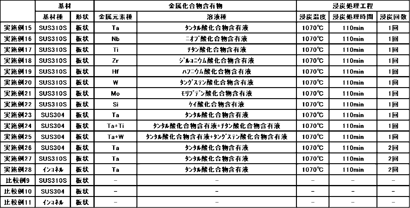

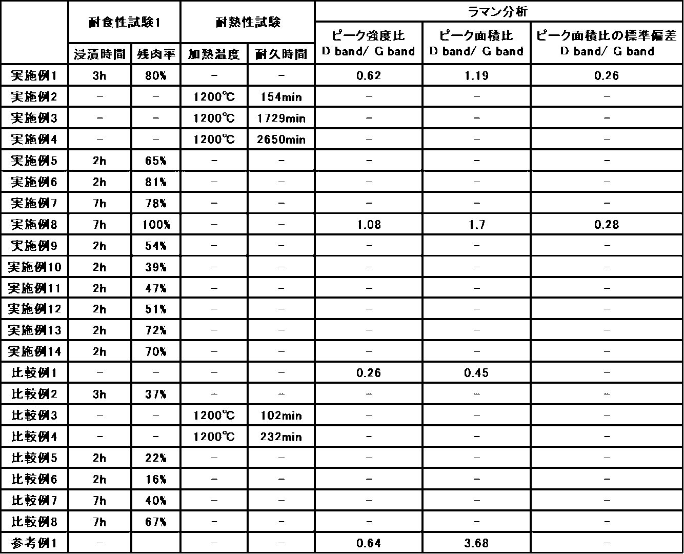
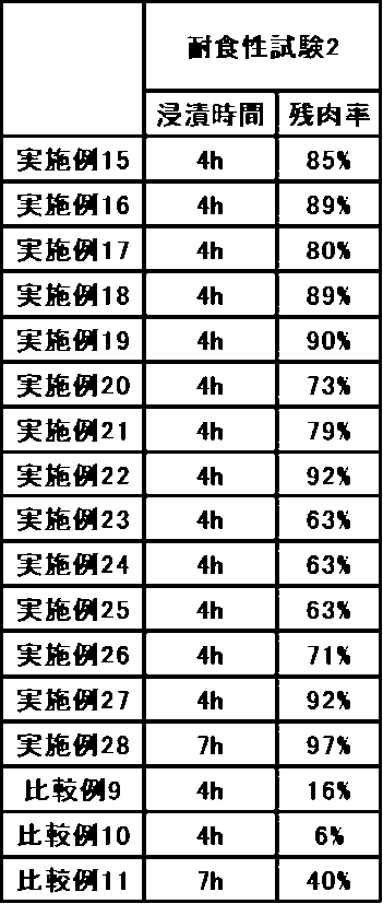
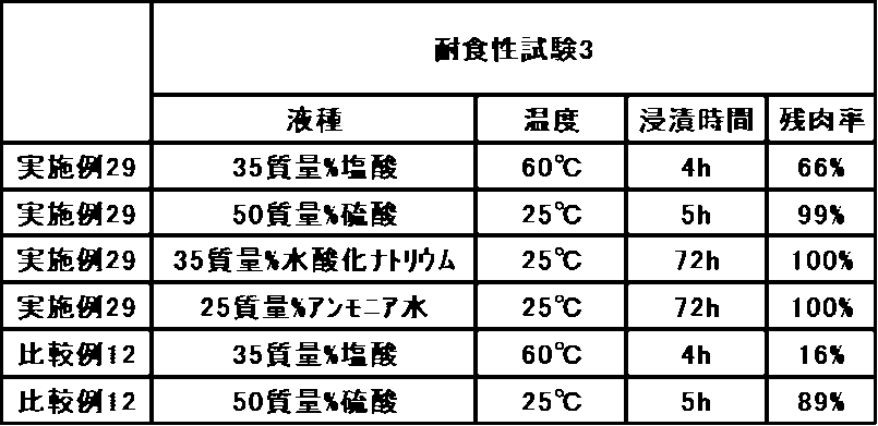
Claims (15)
- 基材上に金属複合体被膜を有する被膜構造体の製造方法であって、
前記基材上に金属化合物含有物を塗布、又は浸漬する工程と、
減圧下又は真空下で、炭素源およびまたは窒素源を供給した状態で、前記基材を加熱することにより、炭化反応、炭窒化反応、又は窒化反応のうち少なくとも1つの反応をさせ、金属複合体被膜を形成する反応工程と、
を有することを特徴とする被膜構造体の製造方法。 - 前記金属化合物含有物を塗布、又は浸漬された前記基材を乾燥する乾燥工程を有することを特徴とする請求項1記載の被膜構造体の製造方法。
- 前記基材上に前記金属化合物含有物を塗布、又は浸漬する工程と前記反応工程とを複数回繰り返すことを特徴とする請求項1に記載の被膜構造体の製造方法。
- 前記基材は、炭素、金属炭化物、純金属、合金、金属酸化物、複合金属酸化物からなる群より選ばれる少なくとも1種を含むことを特徴とする請求項1~3の何れか1つに記載の被膜構造体の製造方法。
- 前記金属複合体被膜は、Ti、Nb、Mo、Hf、Ta、W、Zr、Siから選ばれる少なくとも1種の金属元素の化合物を含むことを特徴とする請求項1~3の何れか1つに記載の被膜構造体の製造方法。
- 前記金属複合体被膜は、Nb、Hf、Taから選ばれる少なくとも1種の金属元素の化合物を含むことを特徴とする請求項1~3の何れか1つに記載の被膜構造体の製造方法。
- 前記金属複合体被膜は、Ti炭化物、Nb炭化物、Mo炭化物、Hf炭化物、Ta炭化物、W炭化物、Zr炭化物、Si炭化物から選ばれる少なくとも1種の金属炭化物を含むことを特徴とする請求項1~3の何れか1つに記載の被膜構造体の製造方法。
- 前記金属化合物含有物が、波長500nm~700nm領域の光透過率の最大値が70%T以上であり、且つ動的光散乱法における前記金属化合物含有物中の粒子の粒子径(D50)が3000nm以下であることを特徴とする請求項1~3の何れか1つに記載の被膜構造体の製造方法。
- 前記反応工程が、炭化反応であり、且つ前記炭素源は、不飽和炭化水素と不活性成分とを含むもの、又は飽和炭化水素の何れかであることを特徴とする請求項1~3の何れか1つに記載の被膜構造体の製造方法。
- 前記反応工程が、炭窒化反応、又は窒化反応であり、且つ前記窒素源は、アンモニアと不活性成分とを含むものであることを特徴とする請求項1~3の何れか1つに記載の被膜構造体の製造方法。
- 前記反応工程は、加熱温度が500℃以上1150℃以下であることを特徴とする請求項1~3の何れか1つに記載の被膜構造体の製造方法。
- 前記反応工程は、加熱時間が0.05時間以上10時間以下であることを特徴とする請求項11に記載の被膜構造体の製造方法。
- 基材上に金属複合体被膜を有する被膜構造体であって、
前記金属複合体被膜は、金属化合物含有物が塗布、又は浸漬された基材を、減圧下又は真空下で、炭素源およびまたは窒素源を供給した状態で、加熱することにより、炭化反応、炭窒化反応、又は窒化反応のうち少なくとも1つの反応をさせることにより、形成されたことを特徴とする被膜構造体。 - 基材上に金属-炭素複合体被膜を有する被膜構造体であって、
前記金属-炭素複合体被膜のラマン分光法におけるD band/G bandピーク面積比が0.5以上2.0以下であることを特徴とする被膜構造体。 - 基材上に金属-炭素複合体被膜を有する被膜構造体であって、
前記金属-炭素複合体被膜のラマン分光法におけるD band/G bandピーク面積比が0.5以上2.0以下であり、且つ前記D band/G bandピーク面積比の標準偏差が0.1以上0.35以下であることを特徴とする被膜構造体。
Priority Applications (4)
| Application Number | Priority Date | Filing Date | Title |
|---|---|---|---|
| CN202480042481.4A CN121399292A (zh) | 2023-06-29 | 2024-06-28 | 被膜结构体的制造方法及被膜结构体 |
| KR1020257042497A KR20260030746A (ko) | 2023-06-29 | 2024-06-28 | 피막 구조체의 제조 방법 및 피막 구조체 |
| JP2024573540A JP7733255B2 (ja) | 2023-06-29 | 2024-06-28 | 被膜構造体の製造方法、及び被膜構造体 |
| EP24832129.1A EP4737612A1 (en) | 2023-06-29 | 2024-06-28 | Coating structure manufacturing method, and coating structure |
Applications Claiming Priority (4)
| Application Number | Priority Date | Filing Date | Title |
|---|---|---|---|
| JP2023107244 | 2023-06-29 | ||
| JP2023-107244 | 2023-06-29 | ||
| JP2023-141902 | 2023-09-01 | ||
| JP2023141902 | 2023-09-01 |
Publications (1)
| Publication Number | Publication Date |
|---|---|
| WO2025005272A1 true WO2025005272A1 (ja) | 2025-01-02 |
Family
ID=93938484
Family Applications (1)
| Application Number | Title | Priority Date | Filing Date |
|---|---|---|---|
| PCT/JP2024/023617 Ceased WO2025005272A1 (ja) | 2023-06-29 | 2024-06-28 | 被膜構造体の製造方法、及び被膜構造体 |
Country Status (6)
| Country | Link |
|---|---|
| EP (1) | EP4737612A1 (ja) |
| JP (1) | JP7733255B2 (ja) |
| KR (1) | KR20260030746A (ja) |
| CN (1) | CN121399292A (ja) |
| TW (1) | TW202503084A (ja) |
| WO (1) | WO2025005272A1 (ja) |
Citations (8)
| Publication number | Priority date | Publication date | Assignee | Title |
|---|---|---|---|---|
| JPH07316778A (ja) * | 1994-03-30 | 1995-12-05 | Nippon Piston Ring Co Ltd | 窒化ピストンリング |
| JP3035571U (ja) * | 1996-09-09 | 1997-03-28 | アイテック株式会社 | 着色パチンコ玉 |
| JPH09209117A (ja) * | 1996-02-06 | 1997-08-12 | Yawata Mekki Kogyo Kk | 遊戯玉の製造方法 |
| WO2012096233A1 (ja) * | 2011-01-13 | 2012-07-19 | 三井金属鉱業株式会社 | 補強された多孔質金属箔およびその製造方法 |
| JP6058846B1 (ja) | 2016-03-24 | 2017-01-11 | 國友熱工株式会社 | 水素浸入抑制方式の真空硬化方法及びこれを使用したワークの製造方法 |
| WO2018155385A1 (ja) * | 2017-02-21 | 2018-08-30 | 日本アイ・ティ・エフ株式会社 | 硬質炭素膜とその製造方法および摺動部材 |
| JP2018188712A (ja) * | 2017-05-11 | 2018-11-29 | 日本アイ・ティ・エフ株式会社 | 硬質炭素膜とその製造方法および摺動部材 |
| JP2021030361A (ja) * | 2019-08-23 | 2021-03-01 | 三菱マテリアル株式会社 | ダイヤモンド被覆切削工具 |
Family Cites Families (4)
| Publication number | Priority date | Publication date | Assignee | Title |
|---|---|---|---|---|
| JP2010007103A (ja) * | 2008-06-24 | 2010-01-14 | Chubu Electric Power Co Inc | アルミニウム部材の製造方法 |
| JP5710901B2 (ja) * | 2010-06-29 | 2015-04-30 | 株式会社フルヤ金属 | 白金成形物の表面硬化方法 |
| JP2016194384A (ja) * | 2015-03-31 | 2016-11-17 | 株式会社神戸製鋼所 | アルミニウム製フィン材 |
| JP7188105B2 (ja) * | 2019-01-16 | 2022-12-13 | 日本製鉄株式会社 | 方向性電磁鋼板 |
-
2024
- 2024-06-28 CN CN202480042481.4A patent/CN121399292A/zh active Pending
- 2024-06-28 EP EP24832129.1A patent/EP4737612A1/en active Pending
- 2024-06-28 WO PCT/JP2024/023617 patent/WO2025005272A1/ja not_active Ceased
- 2024-06-28 JP JP2024573540A patent/JP7733255B2/ja active Active
- 2024-06-28 KR KR1020257042497A patent/KR20260030746A/ko active Pending
- 2024-06-28 TW TW113124367A patent/TW202503084A/zh unknown
Patent Citations (8)
| Publication number | Priority date | Publication date | Assignee | Title |
|---|---|---|---|---|
| JPH07316778A (ja) * | 1994-03-30 | 1995-12-05 | Nippon Piston Ring Co Ltd | 窒化ピストンリング |
| JPH09209117A (ja) * | 1996-02-06 | 1997-08-12 | Yawata Mekki Kogyo Kk | 遊戯玉の製造方法 |
| JP3035571U (ja) * | 1996-09-09 | 1997-03-28 | アイテック株式会社 | 着色パチンコ玉 |
| WO2012096233A1 (ja) * | 2011-01-13 | 2012-07-19 | 三井金属鉱業株式会社 | 補強された多孔質金属箔およびその製造方法 |
| JP6058846B1 (ja) | 2016-03-24 | 2017-01-11 | 國友熱工株式会社 | 水素浸入抑制方式の真空硬化方法及びこれを使用したワークの製造方法 |
| WO2018155385A1 (ja) * | 2017-02-21 | 2018-08-30 | 日本アイ・ティ・エフ株式会社 | 硬質炭素膜とその製造方法および摺動部材 |
| JP2018188712A (ja) * | 2017-05-11 | 2018-11-29 | 日本アイ・ティ・エフ株式会社 | 硬質炭素膜とその製造方法および摺動部材 |
| JP2021030361A (ja) * | 2019-08-23 | 2021-03-01 | 三菱マテリアル株式会社 | ダイヤモンド被覆切削工具 |
Also Published As
| Publication number | Publication date |
|---|---|
| KR20260030746A (ko) | 2026-03-06 |
| JPWO2025005272A1 (ja) | 2025-01-02 |
| TW202503084A (zh) | 2025-01-16 |
| CN121399292A (zh) | 2026-01-23 |
| JP7733255B2 (ja) | 2025-09-02 |
| EP4737612A1 (en) | 2026-05-06 |
Similar Documents
| Publication | Publication Date | Title |
|---|---|---|
| Deysher et al. | Synthesis of Mo4VAlC4 MAX phase and two-dimensional Mo4VC4 MXene with five atomic layers of transition metals | |
| US5364522A (en) | Boride, carbide, nitride, oxynitride, and silicide infiltrated electrochemical ceramic films and coatings and the method of forming such | |
| KR101267679B1 (ko) | 코팅된 초경도 연마 입자 물질 및 초경도 연마 입자를 코팅하는 방법 | |
| Pérez-González et al. | Enhanced photocatalytic activity of TiO2-ZnO thin films deposited by dc reactive magnetron sputtering | |
| CA2720753C (en) | Method for production of carbon nanostructures | |
| Armelao et al. | Au/TiO2 nanosystems: A combined RF-sputtering/sol− gel approach | |
| O'Neill et al. | Anatase thin films on glass from the chemical vapor deposition of titanium (IV) chloride and ethyl acetate | |
| CN107176604B (zh) | 一种碳素材料表面原位生成纳米碳化物涂层的方法 | |
| TWI377176B (ja) | ||
| TW201842210A (zh) | 熔射皮膜、熔射用粉、熔射用粉之製造方法、及熔射皮膜之製造方法 | |
| JP2008512341A (ja) | 金属カーバイド及びその製造方法 | |
| Zhang et al. | Surface chemical modification of CVD diamond films by laser irradiation | |
| JP7698155B2 (ja) | 被膜構造体の製造方法、及び被膜構造体 | |
| Innocenzi et al. | Sol− gel synthesis of β-Al2TiO5 thin films at low temperature | |
| JP7733255B2 (ja) | 被膜構造体の製造方法、及び被膜構造体 | |
| TW201008641A (en) | Method for making glass frit powders using aerosol decomposition | |
| Semaltianos et al. | Laser ablation of a bulk Cr target in liquids for nanoparticle synthesis | |
| JP3912976B2 (ja) | 光触媒膜を有するチタン基材の製造方法及びチタン基材表面の親水化方法 | |
| EP4512777A1 (en) | Niobate particles and method for manufacturing niobate particles | |
| JP2025006444A (ja) | 被膜構造体の製造方法、及び被膜構造体 | |
| Liu et al. | Preparation of titanium nitride nanoparticles from a novel refluxing derived precursor | |
| JP2025010051A (ja) | 金属化合物含有物 | |
| Chopra et al. | Investigation of Ti/CuO interface by X‐ray photoelectron spectroscopy and atomic force microscopy | |
| Dupuis et al. | Catalytic growth of TiO2 nanowires from a TiN thin film | |
| Grilec et al. | Wear rate evaluation of sol-gel TiO2-ZrO2 films by quantitative depth profile analysis |
Legal Events
| Date | Code | Title | Description |
|---|---|---|---|
| WWE | Wipo information: entry into national phase |
Ref document number: 2024573540 Country of ref document: JP |
|
| 121 | Ep: the epo has been informed by wipo that ep was designated in this application |
Ref document number: 24832129 Country of ref document: EP Kind code of ref document: A1 |
|
| WWE | Wipo information: entry into national phase |
Ref document number: 2024832129 Country of ref document: EP |
|
| NENP | Non-entry into the national phase |
Ref country code: DE |
|
| ENP | Entry into the national phase |
Ref document number: 2024832129 Country of ref document: EP Effective date: 20260129 |