WO2025005250A1 - 車両用灯具 - Google Patents
車両用灯具 Download PDFInfo
- Publication number
- WO2025005250A1 WO2025005250A1 PCT/JP2024/023520 JP2024023520W WO2025005250A1 WO 2025005250 A1 WO2025005250 A1 WO 2025005250A1 JP 2024023520 W JP2024023520 W JP 2024023520W WO 2025005250 A1 WO2025005250 A1 WO 2025005250A1
- Authority
- WO
- WIPO (PCT)
- Prior art keywords
- vehicle
- light
- reflecting portion
- lens
- lamp according
- Prior art date
- Legal status (The legal status is an assumption and is not a legal conclusion. Google has not performed a legal analysis and makes no representation as to the accuracy of the status listed.)
- Ceased
Links
Images


Classifications
-
- F—MECHANICAL ENGINEERING; LIGHTING; HEATING; WEAPONS; BLASTING
- F21—LIGHTING
- F21S—NON-PORTABLE LIGHTING DEVICES; SYSTEMS THEREOF; VEHICLE LIGHTING DEVICES SPECIALLY ADAPTED FOR VEHICLE EXTERIORS
- F21S41/00—Illuminating devices specially adapted for vehicle exteriors, e.g. headlamps
- F21S41/10—Illuminating devices specially adapted for vehicle exteriors, e.g. headlamps characterised by the light source
- F21S41/14—Illuminating devices specially adapted for vehicle exteriors, e.g. headlamps characterised by the light source characterised by the type of light source
- F21S41/141—Light emitting diodes [LED]
- F21S41/147—Light emitting diodes [LED] the main emission direction of the LED being angled to the optical axis of the illuminating device
- F21S41/148—Light emitting diodes [LED] the main emission direction of the LED being angled to the optical axis of the illuminating device the main emission direction of the LED being perpendicular to the optical axis
-
- F—MECHANICAL ENGINEERING; LIGHTING; HEATING; WEAPONS; BLASTING
- F21—LIGHTING
- F21S—NON-PORTABLE LIGHTING DEVICES; SYSTEMS THEREOF; VEHICLE LIGHTING DEVICES SPECIALLY ADAPTED FOR VEHICLE EXTERIORS
- F21S41/00—Illuminating devices specially adapted for vehicle exteriors, e.g. headlamps
- F21S41/10—Illuminating devices specially adapted for vehicle exteriors, e.g. headlamps characterised by the light source
- F21S41/14—Illuminating devices specially adapted for vehicle exteriors, e.g. headlamps characterised by the light source characterised by the type of light source
- F21S41/141—Light emitting diodes [LED]
- F21S41/151—Light emitting diodes [LED] arranged in one or more lines
-
- F—MECHANICAL ENGINEERING; LIGHTING; HEATING; WEAPONS; BLASTING
- F21—LIGHTING
- F21S—NON-PORTABLE LIGHTING DEVICES; SYSTEMS THEREOF; VEHICLE LIGHTING DEVICES SPECIALLY ADAPTED FOR VEHICLE EXTERIORS
- F21S41/00—Illuminating devices specially adapted for vehicle exteriors, e.g. headlamps
- F21S41/20—Illuminating devices specially adapted for vehicle exteriors, e.g. headlamps characterised by refractors, transparent cover plates, light guides or filters
- F21S41/25—Projection lenses
- F21S41/265—Composite lenses; Lenses with a patch-like shape
-
- F—MECHANICAL ENGINEERING; LIGHTING; HEATING; WEAPONS; BLASTING
- F21—LIGHTING
- F21S—NON-PORTABLE LIGHTING DEVICES; SYSTEMS THEREOF; VEHICLE LIGHTING DEVICES SPECIALLY ADAPTED FOR VEHICLE EXTERIORS
- F21S41/00—Illuminating devices specially adapted for vehicle exteriors, e.g. headlamps
- F21S41/30—Illuminating devices specially adapted for vehicle exteriors, e.g. headlamps characterised by reflectors
- F21S41/32—Optical layout thereof
- F21S41/33—Multi-surface reflectors, e.g. reflectors with facets or reflectors with portions of different curvature
-
- F—MECHANICAL ENGINEERING; LIGHTING; HEATING; WEAPONS; BLASTING
- F21—LIGHTING
- F21S—NON-PORTABLE LIGHTING DEVICES; SYSTEMS THEREOF; VEHICLE LIGHTING DEVICES SPECIALLY ADAPTED FOR VEHICLE EXTERIORS
- F21S41/00—Illuminating devices specially adapted for vehicle exteriors, e.g. headlamps
- F21S41/30—Illuminating devices specially adapted for vehicle exteriors, e.g. headlamps characterised by reflectors
- F21S41/37—Illuminating devices specially adapted for vehicle exteriors, e.g. headlamps characterised by reflectors characterised by their material, surface treatment or coatings
-
- F—MECHANICAL ENGINEERING; LIGHTING; HEATING; WEAPONS; BLASTING
- F21—LIGHTING
- F21S—NON-PORTABLE LIGHTING DEVICES; SYSTEMS THEREOF; VEHICLE LIGHTING DEVICES SPECIALLY ADAPTED FOR VEHICLE EXTERIORS
- F21S41/00—Illuminating devices specially adapted for vehicle exteriors, e.g. headlamps
- F21S41/30—Illuminating devices specially adapted for vehicle exteriors, e.g. headlamps characterised by reflectors
- F21S41/39—Attachment thereof
-
- F—MECHANICAL ENGINEERING; LIGHTING; HEATING; WEAPONS; BLASTING
- F21—LIGHTING
- F21S—NON-PORTABLE LIGHTING DEVICES; SYSTEMS THEREOF; VEHICLE LIGHTING DEVICES SPECIALLY ADAPTED FOR VEHICLE EXTERIORS
- F21S41/00—Illuminating devices specially adapted for vehicle exteriors, e.g. headlamps
- F21S41/40—Illuminating devices specially adapted for vehicle exteriors, e.g. headlamps characterised by screens, non-reflecting members, light-shielding members or fixed shades
- F21S41/43—Illuminating devices specially adapted for vehicle exteriors, e.g. headlamps characterised by screens, non-reflecting members, light-shielding members or fixed shades characterised by the shape thereof
-
- F—MECHANICAL ENGINEERING; LIGHTING; HEATING; WEAPONS; BLASTING
- F21—LIGHTING
- F21S—NON-PORTABLE LIGHTING DEVICES; SYSTEMS THEREOF; VEHICLE LIGHTING DEVICES SPECIALLY ADAPTED FOR VEHICLE EXTERIORS
- F21S41/00—Illuminating devices specially adapted for vehicle exteriors, e.g. headlamps
- F21S41/60—Illuminating devices specially adapted for vehicle exteriors, e.g. headlamps characterised by a variable light distribution
- F21S41/65—Illuminating devices specially adapted for vehicle exteriors, e.g. headlamps characterised by a variable light distribution by acting on light sources
- F21S41/663—Illuminating devices specially adapted for vehicle exteriors, e.g. headlamps characterised by a variable light distribution by acting on light sources by switching light sources
-
- F—MECHANICAL ENGINEERING; LIGHTING; HEATING; WEAPONS; BLASTING
- F21—LIGHTING
- F21W—INDEXING SCHEME ASSOCIATED WITH SUBCLASSES F21K, F21L, F21S and F21V, RELATING TO USES OR APPLICATIONS OF LIGHTING DEVICES OR SYSTEMS
- F21W2102/00—Exterior vehicle lighting devices for illuminating purposes
- F21W2102/10—Arrangement or contour of the emitted light
- F21W2102/13—Arrangement or contour of the emitted light for high-beam region or low-beam region
- F21W2102/135—Arrangement or contour of the emitted light for high-beam region or low-beam region the light having cut-off lines, i.e. clear borderlines between emitted regions and dark regions
- F21W2102/14—Arrangement or contour of the emitted light for high-beam region or low-beam region the light having cut-off lines, i.e. clear borderlines between emitted regions and dark regions having vertical cut-off lines; specially adapted for adaptive high beams, i.e. wherein the beam is broader but avoids glaring other road users
-
- F—MECHANICAL ENGINEERING; LIGHTING; HEATING; WEAPONS; BLASTING
- F21—LIGHTING
- F21Y—INDEXING SCHEME ASSOCIATED WITH SUBCLASSES F21K, F21L, F21S and F21V, RELATING TO THE FORM OR THE KIND OF THE LIGHT SOURCES OR OF THE COLOUR OF THE LIGHT EMITTED
- F21Y2115/00—Light-generating elements of semiconductor light sources
- F21Y2115/10—Light-emitting diodes [LED]
Definitions
- the present invention relates to a vehicle lamp.
- Vehicle lighting fixtures that form an ADB pattern in front of the vehicle are known (see, for example, Patent Document 1).
- an ADB pattern is formed in front of a vehicle using a so-called reflector-type vehicle lamp, which includes, for example, multiple light sources, a reflector provided for each light source with a reflective surface that reflects the light from each light source to the front of the vehicle, and a projection lens that emits the light reflected by each reflective surface.
- a reflector-type vehicle lamp which includes, for example, multiple light sources, a reflector provided for each light source with a reflective surface that reflects the light from each light source to the front of the vehicle, and a projection lens that emits the light reflected by each reflective surface.
- the present invention was made in consideration of the above, and aims to provide a vehicle lamp that can suppress the occurrence of glare.
- the vehicle lamp of the present invention comprises a plurality of light sources arranged in the left-right direction when mounted on the vehicle, a reflector in which a first reflecting portion that reflects light from the light sources to the front of the vehicle and a second reflecting portion that reflects light from the light sources in a direction different from the front of the vehicle are arranged side by side in the left-right direction, and a projection lens having a plurality of lens portions arranged side by side in the left-right direction and emitting the light reflected by the first reflecting portion to the front of the vehicle to form an illumination pattern.
- the present invention makes it possible to suppress the occurrence of glare.
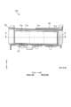
- FIG. 1 is a plan view showing an example of a vehicle lamp according to the present embodiment.
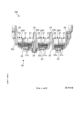
- FIG. 2 is a diagram showing an example of a configuration of a vehicle lamp as viewed from the front side (front).
- FIG. 3 is a diagram showing an example of a configuration of a vehicle lamp as viewed from the front side (front).
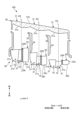
- FIG. 4 is a diagram showing the configuration along the cross section AA in FIG.
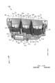
- FIG. 5 is a perspective view showing an example of a vehicle lamp.
- FIG. 6 is a diagram showing an example of a reflector.
- FIG. 7 is a diagram showing an example of a reflector.
- FIG. 8 is a diagram showing an example of the operation of a vehicle lamp.
- FIG. 9 is a diagram showing an example of an illumination pattern by a vehicle lamp.
- the directions of front-rear (front, rear), up-down (up, down), and left-right (left, right) refer to the directions when the vehicle lamp is attached to the vehicle, and are the directions when viewed from the front while sitting in the driver's seat.
- the up-down direction is parallel to the vertical direction
- the left-right direction is the horizontal direction.
- FIG. 1 is a plan view showing an example of a vehicle lamp 100 according to this embodiment.
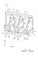
- FIGS. 2 and 3 are diagrams showing an example of the configuration of the vehicle lamp 100 as viewed from the front side (forward). Note that FIG. 3 shows a state in which the projection lens 30 is omitted from FIG. 2.
- FIG. 4 is a diagram showing a schematic configuration along the A-A cross section in FIG. 2.
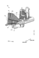
- FIG. 5 is a perspective view showing an example of the vehicle lamp 100. FIG. 5 shows the vehicle lamp 100 as viewed from the rear and above.
- the vehicle lamp 100 shown in Figures 1 to 5 is used as a headlamp of a vehicle.
- the vehicle lamp 100 is attached to the left or right front of the vehicle, for example.
- a vehicle lamp 100 mounted on the left front side of the vehicle will be described. Therefore, in the vehicle lamp 100, the left side in the left-right direction is the inside of the vehicle, and the right side in the left-right direction is the outside of the vehicle.
- a vehicle lamp attached to the right front side of the vehicle can be configured symmetrically on the left and right sides with respect to the vehicle lamp 100.
- the vehicle lamp 100 has a light source 10, a reflector 20, a projection lens 30, and a heat dissipation member 40.
- the vehicle lamp 100 forms an illumination pattern in front of the vehicle.
- the vehicle lamp 100 has a so-called one-sided light distribution configuration. In other words, the vehicle lamp 100 forms the right side of the ADB pattern as an illumination pattern.
- the ADB pattern is formed by combining a vehicle lamp attached to the front right side of the vehicle and a vehicle lamp attached to the front left side of the vehicle. In this case, the vehicle lamp on the front right side of the vehicle forms the ADB pattern from the center to the right side in front of the vehicle, and the vehicle lamp on the front left side of the vehicle forms the ADB pattern from the center to the left side in front of the vehicle.
- the light source 10 is a semiconductor-type light source such as an LED. A plurality of light sources 10 are provided in the left-right direction.
- the light source 10 has a light-emitting surface 11 that emits light. When the vehicle lamp 100 is attached to a vehicle, the light-emitting surface 11 faces downward, for example, and is disposed parallel to the horizontal plane.
- the light source 10 is attached to a substrate 12.
- the substrate 12 is held by a heat dissipation member 40. Circuits and the like for supplying power, electrical signals, and the like to the light source 10 are formed on the substrate 12.
- the reflector 20 has a first reflecting portion 21 and a second reflecting portion 22.
- the first reflecting portion 21 is provided, for example, for each light source 10.
- the first reflecting portions 21 are arranged side by side in the left-right direction corresponding to the respective light sources 10.
- the second reflecting portion 22 reflects the light from the light source 10 in a direction different from the direction toward the front of the vehicle.
- the second reflecting portion 22 functions as a light-dark boundary forming portion for forming the ADB pattern, and also functions as a suppressing portion for suppressing glare by reflecting light so that it does not enter the lens portion 31.
- the detailed configurations of the first reflecting portion 21 and the second reflecting portion 22 will be described later.
- the projection lens 30 emits the light reflected by the first reflecting portion 21 to the front of the vehicle to form an irradiation pattern.
- the projection lens 30 is formed, for example, in a rectangular shape when viewed from the front (front).
- the shape of the projection lens 30 when viewed from the front is not limited to a rectangular shape.
- the projection lens 30 has a shape that is inclined backward from the inside of the vehicle to the outside of the vehicle (see FIG. 1).
- the projection lens 30 has a shape that is inclined upward from the inside of the vehicle to the outside of the vehicle when viewed from the front (see FIG. 2).
- the projection lens 30 has a plurality of lens portions 31.
- the plurality of lens portions 31 are arranged in a line in the left-right direction.
- the plurality of lens portions 31 are connected together. Each lens portion 31 has an entrance surface 31a on which the light reflected by the first reflecting portion 21 is incident. Also, the plurality of lens portions 31 have a common exit surface 31b that emits the light incident from each entrance surface 31a.
- the lens section 31 of the projection lens 30, which is positioned at the innermost part of the vehicle, is set so that the inward diffusion of the emitted light is minimized.
- This configuration allows the space in front of the projection lens 30 and on the inner side of the vehicle to be used effectively, such as by placing other structures in that space, thereby increasing the freedom of layout.
- the lens section 31 of the projection lens 30, which is positioned at the outermost part of the vehicle, is set so that the outward diffusion of the emitted light is minimized.
- This configuration allows the space in front of the projection lens 30 and on the outer side of the vehicle to be used effectively, such as by placing other structures in that space, thereby increasing the freedom of layout.
- the first reflecting portion 21 has a reflecting surface 21a that is concave downward from both left and right sides to the center.
- the first reflecting portion 21 is provided in correspondence with the lens portion 31. Specifically, the first reflecting portion 21 is positioned so that the reflecting surface 21a reflects light toward the corresponding lens portion 31.
- the first reflecting portion 21 is disposed at a position on the inside of the vehicle with respect to the optical axis AX of the corresponding lens portion 31. Therefore, an ADB pattern can be formed in front of the vehicle so as to irradiate toward the outside of the vehicle.
- the first reflecting portion 21 may be disposed so as to straddle the optical axis of the corresponding lens portion 31 in the left-right direction.
- multiple first reflecting portions 21, for example two, are provided for one lens portion 31.
- the two first reflecting portions 21 are disposed in a state of being connected to the left and right.
- the second reflecting portion 22 has a reflective surface 22a that is concave downward from both sides in the left-right direction to the center.
- One second reflecting portion 22 is provided for one lens portion 31. That is, in this embodiment, a plurality (two) of first reflecting portions 21 and one second reflecting portion 22 are arranged in a state of being lined up in the left-right direction in correspondence with one lens portion 31.
- the second reflecting portion 22 is also arranged on the outside of the vehicle in the left-right direction with respect to the first reflecting portion 21. And, three such configurations corresponding to the lens portion 31, the first reflecting portion 21, and the second reflecting portion 22 are arranged in a line in the left-right direction.
- the second reflecting portion 22 reflects light by the reflective surface 22a so as not to be incident on the lens portion 31.
- the second reflecting portion 22 is disposed between the first reflecting portion 21 corresponding to the second reflecting portion 22 and the lens portion 31 adjacent to the lens portion 31 corresponding to the second reflecting portion 22 on the vehicle outer side in ...
- the boundary between the second reflecting portion 22 and the first reflecting portion 21 is formed as a light-dark boundary forming portion 22R along the optical axis AX (shown by the shaded area in FIG. 4).
- the second reflecting portion 22 has a shape in which the rear end portion 22b in the front-to-rear direction faces rearward from the first reflecting portion 21. With this configuration, it becomes difficult for the light reflected by the reflecting surface 22a of the second reflecting portion 22 to enter the lens portion 31.
- the rear end portion 22b may be straight or curved.
- the second reflecting portion 22 has a knurled portion 22c on the side portion on the outer side of the vehicle. The knurled portion 22c scatters light.
- the reflector 20 has a bottom plate 23, a partition wall 24, a light-shielding wall 25, and an outer frame portion 26.
- the bottom plate 23 is disposed, for example, along a horizontal plane, and extends forward from the first reflecting portion 21 and the second reflecting portion 22.
- Figures 6 and 7 are diagrams showing an example of the reflector 20.
- Figure 6 is a perspective view seen from the left rear and above, and
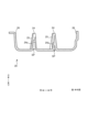
- Figure 7 is a diagram showing the configuration along the B-B cross section in Figure 1.
- the partition wall 24 is provided so as to protrude upward from the bottom plate 23.
- the partition wall 24 is disposed along the front-rear direction between the lens parts 31 adjacent in the left-right direction.
- the partition wall 24 is formed so that the height in the front-rear direction increases toward the front.
- the partition wall 24 has a slope part 24s and a horizontal part 24h.
- the slope part 24s is a part whose height gradually increases from the rear end to the front.
- the horizontal part 24h is a part that extends along a horizontal plane from the front end of the slope part 24s toward the front.
- the amount of material can be reduced at the rear side of the partition wall 24, so that costs can be reduced.
- the partition wall 24 is formed so that the side surface 24a is inclined toward the inside of the vehicle from the top to the bottom. With this configuration, when molding the reflector 20 using a mold, a space SP can be provided inside the partition wall 24 for removing the mold.
- the light shielding wall 25 is disposed between adjacent lens portions 31 in the left-right direction.
- the light shielding wall 25 blocks light reflected by the first reflecting portion 21, which travels toward the outside of the vehicle toward the lens portion 31 adjacent to the lens portion 31 corresponding to the first reflecting portion 21.
- the light shielding wall 25 is provided at the front end of the partition wall 24 disposed on the outside of the vehicle for each lens portion 31.
- the light shielding wall 25 protrudes toward the inside of the vehicle. It is formed so that the amount of protrusion increases from the top to the bottom. With this configuration, the amount of light shielding by the light shielding wall 25 can be minimized.
- the outer frame 26 is disposed at both left and right ends of the reflector 20.
- the outer frame 26 is formed so as to bend upward from the bottom plate 23.
- FIG. 8 is a diagram showing an example of the operation of the vehicle lamp 100.
- the light source 10 in the vehicle lamp 100 When the light source 10 in the vehicle lamp 100 is turned on, light is emitted from the light-emitting surface 11. A portion of the light emitted from the light-emitting surface 11 reaches the reflecting surface 21a of the first reflecting portion 21. A portion of the light that reaches the reflecting surface 21a, light L1, is reflected forward toward the corresponding lens portion 31 and is irradiated forward of the vehicle via the lens portion 31 to form the ADB pattern.
- This light L2 is blocked by the light-shielding wall 25 at the tip of the partition wall 24. This prevents the light L2 from entering the lens portion 31 next to the corresponding lens portion 31.
- a portion of the light L3 emitted from the light-emitting surface 11 reaches the reflecting surface 22a of the second reflecting portion 22.
- the light L3 that reaches the reflecting surface 22a is reflected in a direction different from the forward direction, and is reflected or absorbed by the partition wall 24, for example, or diffused by the knurled portion 22c.
- the light L3 that reaches the second reflecting portion 22 is prevented from entering the lens portion 31. In this way, the light L3 is prevented from being emitted in front of the vehicle, thereby preventing the occurrence of glare.
- FIG. 9 is a diagram showing an example of an irradiation pattern P by the vehicle lamp 100.
- the line H-H indicates a horizontal line
- the line V-V indicates a line parallel to the vertical direction (hereinafter referred to as a vertical line).
- the light L1 emitted from the exit surface 31b of the projection lens 30 forms an irradiation pattern P in front of the vehicle.
- the irradiation pattern P is arranged in a state in which patterns P1 to P6 corresponding to individual light sources 10 are arranged side by side with some overlapping in the left and right direction. Note that in FIG.
- the symbols of the light sources 10 corresponding to the patterns P1, P2, P3, P4, P5, and P6 are shown as S1, S2, S3, S4, S5, and S6, respectively.
- the vehicle lamp 100 according to this embodiment has a so-called one-sided light distribution. Therefore, the irradiation pattern P corresponds to the right part of the ADB pattern.
- the ADB pattern is formed by combining it with the irradiation pattern of the vehicle lamp arranged in the front left part of the vehicle.
- the light-dark boundary forming portion 22R is provided, so that the end on the left side in the figure becomes a straight line that rises up. In other words, the light-dark boundary is clearly formed.
- the patterns P4, P5, and P6 of the first reflecting portion 21 adjacent to the second reflecting portion 22 are irradiated near the V-V line.
- the vehicle lamp 100 includes a plurality of light sources 10 arranged in the left-right direction when mounted on the vehicle, a reflector 20 in which a first reflecting portion 21 that reflects light from the light sources 10 toward the front of the vehicle and a second reflecting portion 22 that reflects light from the light sources 10 in a direction different from the front of the vehicle are arranged side by side in the left-right direction, and a projection lens 30 having a plurality of lens portions 31 arranged side by side in the left-right direction and emitting the light reflected by the first reflecting portion 21 toward the front of the vehicle to form an ADB pattern.
- the second reflecting portion 22 is arranged to be aligned with the first reflecting portion 21 in the left-right direction, so that when light from the light source 10 deviates left-right from the first reflecting portion 21 and reaches the second reflecting portion 22, the light can be reflected in a direction other than the front of the vehicle. This makes it possible to prevent light that deviates left-right from the first reflecting portion 21 from entering the lens portion 31 in an unintended manner, thereby suppressing the occurrence of glare.
- a first reflecting portion 21 and a second reflecting portion 22 are arranged on the reflector 20 in correspondence with each lens portion 31, with the first reflecting portion 21 being arranged at a position on the inside of the vehicle relative to the optical axis of the corresponding lens portion 31, and the second reflecting portion 22 being arranged at a position on the outside of the vehicle relative to the optical axis of the corresponding lens portion 31.
- the first reflecting portion 21 is positioned on the inside of the vehicle with respect to the optical axis of the corresponding lens portion 31, so that the light from the first reflecting portion 21 can be efficiently irradiated forward toward the outside of the vehicle via the lens portion 31.
- the shape of the reflecting surface 22a is concave and the rear end portion 22b of the second reflecting portion 22 is shaped to face rearward from the first reflecting portion 21, so that the generation of glare from the lens portion 31 toward the inside of the vehicle forward can be suppressed.
- the second reflecting portion 22 is disposed between the first reflecting portion 21 corresponding to the second reflecting portion 22 and the lens portion 31 adjacent to the lens portion 31 corresponding to the second reflecting portion 22 in the left-right direction.
- the second reflecting part 22 is arranged in the left-right direction between the first reflecting part 21 that corresponds to the second reflecting part 22 and the lens part 31 that is adjacent to the lens part 31 that corresponds to the second reflecting part 22 on the outside of the vehicle in the left-right direction. Therefore, by arranging the second reflecting part 22 at the position of the light-dark boundary forming part, it is possible to suppress the reflection of light from the position of the light-dark boundary forming part toward the lens part 31, and to suppress the occurrence of glare.
- the boundary between the second reflecting portion 22 and the first reflecting portion 21 is formed as a light-dark boundary forming portion 22R along the optical axis AX.
- the boundary with the first reflecting portion 21 is formed as the light-dark boundary forming portion 22R along the optical axis AX, so that light is prevented from being reflected from the position of the light-dark boundary forming portion toward the lens portion 31, thereby suppressing the occurrence of glare.
- the second reflecting portion 22 has a knurled portion 22c.
- the light that reaches the knurled portion 22c of the second reflecting portion 22 can be diffused by the knurled portion 22c, thereby suppressing the occurrence of glare.
- the lens portion 31 of the projection lens 30 that is positioned on the innermost side of the vehicle forms patterns P1 and P4 that cause the least inward diffusion of the emitted light.
- This configuration allows the space in front of the projection lens 30 and inside the vehicle to be used effectively, for example by placing other structures there, providing greater freedom in layout.
- the lens portion 31 of the projection lens 30 that is positioned on the outermost side of the vehicle forms patterns P3 and P6 that cause the least outward diffusion of the emitted light.
- This configuration allows the space in front of the projection lens 30 and outside the vehicle to be used effectively, for example by placing other structures there, providing greater freedom in layout.
- the projection lens 30 is inclined backward from the inside to the outside of the vehicle.
- the shape of the projection lens 30 is tilted backward from the inside to the outside of the vehicle, making it easier to follow the shape of the surroundings and improving layout flexibility.
- first reflecting sections 21 corresponding to one lens section 31 are provided in the left-right direction.
- the light source 10 is provided corresponding to the first reflecting portion 21, and no corresponding light source 10 is provided in the second reflecting portion 22.
- the light/dark boundary can be formed more reliably, improving the quality of the irradiation pattern P.
- the reflector 20 has a light-shielding wall 25 facing the inside of the vehicle between adjacent lens portions 31 in the left-right direction.
- This configuration can block light that is reflected by the first reflecting portion 21 and travels toward the lens portion 31 adjacent to the corresponding lens portion 31. This can prevent unintended light from entering the lens portion 31, thereby suppressing the occurrence of glare.
- the reflector 20 has a partition wall 24 along the front-rear direction between adjacent lens portions 31 in the left-right direction, and the light-shielding wall 25 is provided at the front end of the partition wall 24.
- the light shielding wall 25 is provided at the front end of the partition wall 24, so that the light reflected by the first reflecting portion 21 and traveling toward the lens portion 31 adjacent to the corresponding lens portion 31 can be more reliably blocked by the light shielding wall 25.
- the partition wall 24 is formed so that its vertical height increases toward the front.
- the light emitted from the light source 10 that travels diagonally forward toward the partition 24 can be reliably blocked on the front side of the partition 24.
- the amount of material required on the rear side of the partition 24 can be reduced, which helps keep costs down.
- the partition wall 24 is formed so that it slopes inward toward the vehicle from the top to the bottom.
- This configuration makes it possible to prevent the resin from becoming too thick when molding the reflector 20 using a mold.
- the light blocking wall 25 is formed so that the amount of protrusion toward the inside of the vehicle decreases from the bottom to the top.
- the amount of light blocking by the light blocking wall 25 can be kept to a minimum by reducing the amount of protrusion from the bottom to the top of the light blocking wall 25 toward the inside of the vehicle.
Landscapes
- Engineering & Computer Science (AREA)
- General Engineering & Computer Science (AREA)
- Physics & Mathematics (AREA)
- Microelectronics & Electronic Packaging (AREA)
- Optics & Photonics (AREA)
- Non-Portable Lighting Devices Or Systems Thereof (AREA)
Abstract
Description
Claims (15)
- 車両搭載状態における左右方向に配置される複数の光源と、
前記光源からの光を車両前方へ反射する第1反射部と、前記光源からの光を前記車両前方とは異なる方向へ反射する第2反射部とが左右方向に並んだ状態で配置されるリフレクタと、
左右方向に並んだ状態で配置され、前記第1反射部で反射された光を車両前方に出射して照射パターンを形成する複数のレンズ部を有する投影レンズと
を備える車両用灯具。 - 前記リフレクタには、それぞれの前記レンズ部ごとに前記第1反射部及び前記第2反射部が対応して配置され、
前記第1反射部は、対応する前記レンズ部の光軸に対して車両内側となる位置に配置され、
前記第2反射部は、それぞれの前記レンズ部の光軸に対して車両外側となる位置に配置される
請求項1に記載の車両用灯具。 - 前記第2反射部は、左右方向について、当該第2反射部に対応する前記第1反射部と、当該第2反射部に対応する前記レンズ部に対して左右方向に隣り合うレンズ部と、の間に配置される
請求項1に記載の車両用灯具。 - 前記第2反射部は、前記第1反射部との境界が光軸に沿った明暗境界形成部として形成されている
請求項1に記載の車両用灯具。 - 前記第2反射部は、ローレット部を有する
請求項1に記載の車両用灯具。 - 前記投影レンズの最も車両内側に配置される前記レンズ部は、出射光の内側拡散が最も少ない配光パターンを形成する
請求項1に記載の車両用灯具。 - 前記投影レンズの最も車両外側に配置される前記レンズ部は、出射光の外側拡散が最も少ない配光パターンを形成する
請求項1に記載の車両用灯具。 - 前記投影レンズは、車両内側から外側にかけて後方に傾いた形状である
請求項1に記載の車両用灯具。 - 1つの前記レンズ部に対応する前記第1反射部が、左右方向に複数設けられる
請求項2に記載の車両用灯具。 - 前記光源は、前記第1反射部に対応して設けられ、
前記第2反射部には、対応する前記光源が設けられない
請求項1に記載の車両用灯具。 - 前記リフレクタは、左右方向に隣り合う前記レンズ部同士の間に車両内側に向けた遮光壁を有する
請求項1に記載の車両用灯具。 - 前記リフレクタは、左右方向に隣り合う前記レンズ部同士の間に前後方向に沿った隔壁を有し、
前記遮光壁は、前記隔壁の前方の端部に設けられる
請求項11に記載の車両用灯具。 - 前記隔壁は、前方に向けて上下方向の高さが高くなるように形成される
請求項12に記載の車両用灯具。 - 前記隔壁は、上部から下部にかけて車両内側に傾くように形成される
請求項12に記載の車両用灯具。 - 前記遮光壁は、下部から上部にかけて車両内側への突出量が少なくなるように形成される
請求項12に記載の車両用灯具。
Priority Applications (2)
| Application Number | Priority Date | Filing Date | Title |
|---|---|---|---|
| EP24832108.5A EP4737796A1 (en) | 2023-06-30 | 2024-06-28 | Vehicle lamp |
| CN202480041119.5A CN121532594A (zh) | 2023-06-30 | 2024-06-28 | 车辆用灯具 |
Applications Claiming Priority (2)
| Application Number | Priority Date | Filing Date | Title |
|---|---|---|---|
| JP2023-108907 | 2023-06-30 | ||
| JP2023108907A JP2025007478A (ja) | 2023-06-30 | 2023-06-30 | 車両用灯具 |
Publications (1)
| Publication Number | Publication Date |
|---|---|
| WO2025005250A1 true WO2025005250A1 (ja) | 2025-01-02 |
Family
ID=93939135
Family Applications (1)
| Application Number | Title | Priority Date | Filing Date |
|---|---|---|---|
| PCT/JP2024/023520 Ceased WO2025005250A1 (ja) | 2023-06-30 | 2024-06-28 | 車両用灯具 |
Country Status (4)
| Country | Link |
|---|---|
| EP (1) | EP4737796A1 (ja) |
| JP (1) | JP2025007478A (ja) |
| CN (1) | CN121532594A (ja) |
| WO (1) | WO2025005250A1 (ja) |
Citations (2)
| Publication number | Priority date | Publication date | Assignee | Title |
|---|---|---|---|---|
| US5045982A (en) * | 1989-03-17 | 1991-09-03 | Whelen Technologies, Inc. | Wide angle warning light |
| JP2019003832A (ja) | 2017-06-15 | 2019-01-10 | 市光工業株式会社 | 車両用灯具 |
-
2023
- 2023-06-30 JP JP2023108907A patent/JP2025007478A/ja active Pending
-
2024
- 2024-06-28 WO PCT/JP2024/023520 patent/WO2025005250A1/ja not_active Ceased
- 2024-06-28 CN CN202480041119.5A patent/CN121532594A/zh active Pending
- 2024-06-28 EP EP24832108.5A patent/EP4737796A1/en active Pending
Patent Citations (2)
| Publication number | Priority date | Publication date | Assignee | Title |
|---|---|---|---|---|
| US5045982A (en) * | 1989-03-17 | 1991-09-03 | Whelen Technologies, Inc. | Wide angle warning light |
| JP2019003832A (ja) | 2017-06-15 | 2019-01-10 | 市光工業株式会社 | 車両用灯具 |
Also Published As
| Publication number | Publication date |
|---|---|
| CN121532594A (zh) | 2026-02-13 |
| JP2025007478A (ja) | 2025-01-17 |
| EP4737796A1 (en) | 2026-05-06 |
Similar Documents
| Publication | Publication Date | Title |
|---|---|---|
| KR100934425B1 (ko) | 차량용 전조등의 등기구 유닛 | |
| WO2021085298A1 (ja) | 車両用導光体及び車両用前照灯 | |
| KR20080087656A (ko) | 차량용 전조등의 등기구 유닛 | |
| JP2005251435A (ja) | 車両用前照灯 | |
| JP7622592B2 (ja) | 車両用導光体及び車両用灯具ユニット | |
| JP7472618B2 (ja) | 車両用導光体及び車両用灯具ユニット | |
| JP7530281B2 (ja) | 灯具ユニット | |
| JP2022129347A (ja) | 車両用ランプおよびそのランプを含む車両 | |
| CN116368329A (zh) | 车辆用前照灯 | |
| JP6854174B2 (ja) | 車輌用灯具 | |
| WO2025005250A1 (ja) | 車両用灯具 | |
| JP5335605B2 (ja) | 車両用前照灯 | |
| JP2021072254A (ja) | 車両用導光体及び車両用前照灯 | |
| WO2024053582A1 (ja) | 車両用前照灯 | |
| JP5982986B2 (ja) | 車両用前照灯 | |
| JP7819600B2 (ja) | 車両用灯具 | |
| JP7826739B2 (ja) | 車両用灯具 | |
| JP7459481B2 (ja) | 車両用導光体及び車両用前照灯 | |
| WO2024053324A1 (ja) | 車輌用灯具 | |
| JP2025019744A (ja) | 車両用灯具 | |
| JP2023148583A (ja) | 車両用灯具 | |
| JP7757744B2 (ja) | 車両用前照灯 | |
| JP7505186B2 (ja) | 車両用灯具 | |
| JP7528742B2 (ja) | 車両用前照灯 | |
| JP7718226B2 (ja) | 車両用灯具 |
Legal Events
| Date | Code | Title | Description |
|---|---|---|---|
| 121 | Ep: the epo has been informed by wipo that ep was designated in this application |
Ref document number: 24832108 Country of ref document: EP Kind code of ref document: A1 |
|
| WWE | Wipo information: entry into national phase |
Ref document number: 2024832108 Country of ref document: EP |
|
| NENP | Non-entry into the national phase |
Ref country code: DE |
|
| ENP | Entry into the national phase |
Ref document number: 2024832108 Country of ref document: EP Effective date: 20260130 |
|
| ENP | Entry into the national phase |
Ref document number: 2024832108 Country of ref document: EP Effective date: 20260130 |