WO2025005246A1 - 作業機、及び作業機に用いられるスピンドルの製造方法 - Google Patents
作業機、及び作業機に用いられるスピンドルの製造方法 Download PDFInfo
- Publication number
- WO2025005246A1 WO2025005246A1 PCT/JP2024/023510 JP2024023510W WO2025005246A1 WO 2025005246 A1 WO2025005246 A1 WO 2025005246A1 JP 2024023510 W JP2024023510 W JP 2024023510W WO 2025005246 A1 WO2025005246 A1 WO 2025005246A1
- Authority
- WO
- WIPO (PCT)
- Prior art keywords
- wall portion
- spindle
- axial direction
- shaft
- corner
- Prior art date
- Legal status (The legal status is an assumption and is not a legal conclusion. Google has not performed a legal analysis and makes no representation as to the accuracy of the status listed.)
- Ceased
Links
Images




Classifications
-
- B—PERFORMING OPERATIONS; TRANSPORTING
- B23—MACHINE TOOLS; METAL-WORKING NOT OTHERWISE PROVIDED FOR
- B23C—MILLING
- B23C3/00—Milling particular work; Special milling operations; Machines therefor
-
- B—PERFORMING OPERATIONS; TRANSPORTING
- B23—MACHINE TOOLS; METAL-WORKING NOT OTHERWISE PROVIDED FOR
- B23P—METAL-WORKING NOT OTHERWISE PROVIDED FOR; COMBINED OPERATIONS; UNIVERSAL MACHINE TOOLS
- B23P15/00—Making specific metal objects by operations not covered by a single other subclass or a group in this subclass
-
- B—PERFORMING OPERATIONS; TRANSPORTING
- B25—HAND TOOLS; PORTABLE POWER-DRIVEN TOOLS; MANIPULATORS
- B25B—TOOLS OR BENCH DEVICES NOT OTHERWISE PROVIDED FOR, FOR FASTENING, CONNECTING, DISENGAGING, OR HOLDING
- B25B21/00—Portable power-driven screw or nut setting or loosening tools; Attachments for drilling apparatus serving the same purpose
-
- B—PERFORMING OPERATIONS; TRANSPORTING
- B25—HAND TOOLS; PORTABLE POWER-DRIVEN TOOLS; MANIPULATORS
- B25B—TOOLS OR BENCH DEVICES NOT OTHERWISE PROVIDED FOR, FOR FASTENING, CONNECTING, DISENGAGING, OR HOLDING
- B25B21/00—Portable power-driven screw or nut setting or loosening tools; Attachments for drilling apparatus serving the same purpose
- B25B21/02—Portable power-driven screw or nut setting or loosening tools; Attachments for drilling apparatus serving the same purpose with means for imparting impact to screwdriver blade or nut socket
-
- B—PERFORMING OPERATIONS; TRANSPORTING
- B25—HAND TOOLS; PORTABLE POWER-DRIVEN TOOLS; MANIPULATORS
- B25F—COMBINATION OR MULTI-PURPOSE TOOLS NOT OTHERWISE PROVIDED FOR; DETAILS OR COMPONENTS OF PORTABLE POWER-DRIVEN TOOLS NOT PARTICULARLY RELATED TO THE OPERATIONS PERFORMED AND NOT OTHERWISE PROVIDED FOR
- B25F5/00—Details or components of portable power-driven tools not particularly related to the operations performed and not otherwise provided for
Definitions
- the present invention relates to a working machine and a method for manufacturing a spindle used in the working machine.
- the driving force of the motor is transmitted to the impact mechanism by a reducer consisting of a planetary gear mechanism, and a rotational force and an impact force are applied to a tip tool such as a driver bit attached to the impact mechanism.
- This impact mechanism is composed of a spindle that rotates by the driving force of the motor, a hammer connected to the spindle by a cam mechanism, and an anvil connected to the hammer by the impact claws of the hammer so that it can rotate together with the hammer.
- the spindle also rotatably supports an idle gear that constitutes the reduction mechanism.
- the spindle has a shaft portion and a pair of disk-shaped wall portions that extend radially outward from the shaft portion, and the outer peripheries of the pair of wall portions are connected by a connecting portion.
- the idle gear is housed between the pair of wall portions.
- the connecting portion connecting the pair of wall portions may be formed in a roughly fan-like shape with the radially inner end portion as the center when viewed from the axial direction.
- the connecting portion when viewed from the axial direction, the connecting portion has a corner that protrudes toward the axis of the spindle. For this reason, stress concentration occurs at the corner, and if the connecting portion is damaged, the durability of the spindle (work machine) may decrease.
- the present invention aims to provide a working machine that can improve durability and workability, and a manufacturing method for a spindle used in the working machine.
- One or more embodiments of the present invention are a working machine including a motor, a spindle that rotates by the driving force of the motor, and a tool holder that holds a tool tip and is driven by the rotational force of the spindle, the spindle including a shaft portion, a first wall portion extending radially outward from the shaft portion, a second wall portion extending radially outward from the shaft portion and arranged opposite the first wall portion in the axial direction of the shaft portion, a connecting portion that connects the first wall portion and the second wall portion radially outward from the shaft portion and between the first wall portion and the second wall portion and has a chamfered corner portion that is convex toward the shaft portion when viewed from the axial direction, and a chamfering hole portion that is formed from one of the first wall portion and the second wall portion to the other of the first wall portion and the second wall portion with the depth direction being the axial direction, and a part of the inner circumferential surface coinciding with the corner portion when viewed
- One or more embodiments of the present invention are a work machine in which the chamfering hole penetrates one of the first wall portion and the second wall portion, and the chamfering hole formed in the other of the first wall portion and the second wall portion is formed in a concave shape that opens into one of the first wall portion and the second wall portion.
- One or more embodiments of the present invention are a work machine in which the chamfering hole penetrates the first wall portion and the second wall portion.
- One or more embodiments of the present invention are a work machine in which the chamfering hole is formed in a circular shape when viewed from the axial direction.
- One or more embodiments of the present invention are a work machine in which the chamfering hole is formed as an elongated hole with the circumferential direction of the spindle as the longitudinal direction when viewed from the axial direction.
- the connecting portion includes a pair of side surfaces that, when viewed from the axial direction, extend in a direction approaching each other as they move radially inward of the shaft portion, and the corner portion is formed at the portion where the pair of side surfaces intersect, and a base R portion is formed at the boundary between the side surfaces and the inner circumferential surfaces of the first wall portion and the second wall portion.
- One or more embodiments of the present invention are a work machine in which a portion of the chamfering hole overlaps with the shaft portion when viewed from the axial direction.
- One or more embodiments of the present invention are a work machine in which the tool tip is located on one side of the spindle in the axial direction, the second wall portion is disposed on one side of the first wall portion in the axial direction, and the second wall portion is provided with a thick portion, and when viewed from the axial direction, the thick portion overlaps with the corner portion.
- One or more embodiments of the present invention are a work machine in which three connecting portions are provided between the first wall portion and the second wall portion, and the connecting portions are arranged at equal intervals in the circumferential direction of the shaft portion.
- One or more embodiments of the present invention are a work machine in which three transmission members for transmitting the driving force of the motor are disposed between the first wall portion and the second wall portion, the chamfering hole portion is disposed adjacent to the radially inner side of the shaft portion relative to the corner portion when viewed from the axial direction, and the transmission members and the connecting portion are disposed alternately in the circumferential direction of the shaft portion.
- One or more embodiments of the present invention are a method for manufacturing a spindle for use in a work machine, the spindle comprising a shaft portion, a first wall portion extending radially outward from the shaft portion, a second wall portion extending radially outward from the shaft portion and arranged opposite the first wall portion in the axial direction of the shaft portion, a connecting portion that connects the first wall portion and the second wall portion radially outward of the shaft portion and between the first wall portion and the second wall portion and has a chamfered corner, and a front end portion formed in the first wall portion and the second wall portion with the depth direction being the axial direction.
- the method for manufacturing a spindle includes a chamfering hole, part of the inner circumferential surface of which coincides with the corner when viewed from the axial direction, and includes a first step of forming the shaft portion and a protrusion extending radially outward from the shaft portion, a second step of cutting the protrusion from the radially outward side with an end mill to form the first wall portion, the second wall portion, and the connecting portion on the protrusion, and a third step of cutting the protrusion from one side or the other side in the axial direction with a drill or an end mill to form the chamfering hole and chamfer the corner.
- One or more embodiments of the present invention can improve durability and processability.
- FIG. 1 is a vertical sectional view showing an impact tool according to an embodiment of the present invention.
- FIG. 2 is an enlarged vertical cross-sectional view of an upper portion of the impact tool shown in FIG. 1 .
- 3A is a side view of the spindle shown in FIG. 2 as seen from the right side
- FIG. 3B is a cross-sectional view (cross-sectional view taken along line 3B-3B in FIG. 3A) as seen from the front side showing the inside of the carrier portion of the spindle in FIG. 2A.
- 4 is a perspective view of the rear part of the carrier portion in the broken state shown in FIG. 3B, as viewed from diagonally forward right.
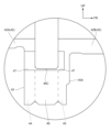
- FIG. 4 is a cross-sectional view showing the lower plate connecting portion and the chamfering hole portion shown in FIG.
- FIG. 3(B) is a perspective view corresponding to FIG. 4 and showing a rear part of a carrier part of a spindle of a comparative example.
- 6 is a cross-sectional view corresponding to FIG. 5 and showing a modified example of the chamfering hole portion shown in FIG. 5 .
- 6 is a cross-sectional view corresponding to FIG. 5 and showing another modified example of the chamfering hole shown in FIG. 5.
- FIG. 4 is a cross-sectional view corresponding to FIG. 3(B) and illustrating a modified example of the shape of the chamfering hole portion shown in FIG. 3(B).
- the impact tool 1 as a work machine according to this embodiment, with reference to the drawings.
- the arrows UP, FR, and RH shown as appropriate in the drawings indicate the upper side, front side, and right side of the impact tool 1, respectively.
- the up-down, front-back, and left-right directions when used, they refer to the up-down, front-back, and left-right directions of the impact tool 1, unless otherwise specified.
- the impact tool 1 is configured as an electric tool that applies a rotational force and an impact force to a tip tool 70, such as a driver bit, attached to the front end of the impact tool 1 to perform fastening processing, etc.
- the impact tool 1 includes a housing 10 that forms the outer shell of the impact tool 1, a motor 20 housed in the housing 10, and a driving force transmission mechanism 30 that transmits the driving force of the motor 20 to the tip tool 70.
- a driving force transmission mechanism 30 that transmits the driving force of the motor 20 to the tip tool 70.
- the housing 10 is formed in a hollow, roughly I-shape when viewed from the right side. Specifically, the housing 10 includes an upper housing portion 10A that forms the upper end of the housing 10 and extends in the front-to-rear direction, a handle portion 10B that extends downward from the middle of the upper housing portion 10A in the front-to-rear direction, and a lower housing portion 10C that forms the lower end of the housing 10.
- the housing 10 is made up of multiple housing members, and the housing 10 is formed by assembling these housing members together.
- a trigger 12 is provided at the upper end of the handle portion 10B, and the trigger 12 protrudes forward from the handle portion 10B and can be pulled rearward.
- a switch mechanism 14 is provided on the handle portion 10B behind the trigger 12. The switch mechanism 14 has a switch (not shown), and pulling the trigger 12 switches the switch from off to on.
- a controller 16 is provided in the lower housing portion 10C.
- a switch of the switch mechanism 14 is electrically connected to the controller 16, and an output signal corresponding to the operation state of the trigger 12 is output from the switch to the controller 16.
- a battery 18 is removably attached to the lower housing portion 10C. The battery 18 is electrically connected to the controller 16, and supplies power to a motor 20, which will be described later.
- the motor 20 is housed in the rear end of the upper housing portion 10A and is electrically connected to the controller 16.
- the motor 20 includes a drive shaft 21 whose axial direction is the front-to-rear direction, a rotor 22 connected to the drive shaft 21 so as to be rotatable together with it, and a substantially cylindrical stator 23 arranged radially outside the rotor 22.
- the rear end of the drive shaft 21 is rotatably supported by a first motor bearing 24 fixed to the housing 10. Meanwhile, the front end portion of the drive shaft 21 is rotatably supported by a second motor bearing 26, which is fixed to a gear case 25 housed in the upper housing portion 10A.
- the gear case 25 is formed in a roughly stepped cylindrical shape with the axial direction being the front-to-rear direction, and the second motor bearing 26 is fitted into roughly the center of the gear case 25.
- the front end of the drive shaft 21 is disposed within the gear case 25, protruding forward from the second motor bearing 26.
- the driving force transmission mechanism 30 includes a rotary impact mechanism 40 that applies a rotational force and an impact force to the tip tool 70, and a speed reduction mechanism 32 that reduces the rotational force of the motor 20 and transmits it to the rotary impact mechanism 40.
- the reduction mechanism 32 is configured as a planetary gear mechanism and is disposed within the gear case 25.
- the reduction mechanism 32 includes a sun gear 33 fixed to the front end of the drive shaft 21 of the motor 20, a ring-shaped ring gear 34 provided radially outside the sun gear 33, and a plurality of (three in this embodiment) idle gears 35 serving as transmission members provided between the sun gear 33 and the ring gear 34.
- the ring gear 34 is held by the gear case 25 via a damper, and internal teeth are formed on the inner peripheral surface of the ring gear 34.
- the idle gear 35 is rotatably mounted on the carrier portion 43 as a protruding portion of the spindle 41 described later. Specifically, the idle gear 35 is housed in a gear chamber 43A (see FIG. 3A) formed in the carrier portion 43, and is supported by a needle roller 36 provided in the gear chamber 43A so as to be rotatable with the front-rear direction as the axial direction.
- the idle gear 35 is also meshed with the internal teeth of the sun gear 33 and the ring gear 34.
- the rotary impact mechanism 40 includes a spindle 41, a hammer 50, and an anvil 56 as a tool holder.
- the spindle 41 has a spindle shaft 42 as a substantially cylindrical shaft portion with the axial direction being the front-rear direction, and the spindle shaft 42 is arranged coaxially with the drive shaft 21 of the motor 20.
- the sun gear 33 described above is inserted into the rear end portion of the spindle shaft 42, and the rear end portion of the spindle shaft 42 is rotatably supported by a bearing 60 provided in the gear case 25.
- a carrier portion 43 extending radially outward from the spindle shaft 42 is provided on the rear end side portion of the outer periphery of the spindle shaft 42, and the idle gear 35 described above is rotatably provided on the carrier portion 43.
- the configuration of the carrier portion 43 will be described later.
- the rear part of the spindle shaft 42 beyond the carrier part 43 is the rear shaft part 42A (broadly speaking, an element that can be understood as the first shaft part), and the front part of the spindle shaft 42 beyond the carrier part 43 is the front shaft part 42B (broadly speaking, an element that can be understood as the second shaft part).
- the outer diameter of the rear shaft part 42A is set slightly smaller than the outer diameter of the front shaft part 42B.
- a pair of spindle cam grooves 42C is formed on the outer peripheral surface of the front part of the front shaft part 42B.
- the pair of spindle cam grooves 42C extend in a substantially V-shape when viewed from the radial outside of the front shaft part 42B.
- the spindle cam groove 42C is formed in a substantially semicircular shape that is open to the radial outside of the front shaft part 42B in a cross-sectional view viewed from its longitudinal direction.
- a steel ball 52 is inserted into the front end part of the spindle cam groove 42C so that it can roll.
- the hammer 50 is formed in a generally cylindrical shape with its axial direction extending in the front-to-rear direction, and an insertion hole 50A penetrates the center of the hammer 50 in the front-to-rear direction.
- the front part of the front shaft portion 42B of the spindle shaft 42 is inserted into the insertion hole 50A, and the hammer 50 is rotatably supported by the spindle 41.
- a pair of hammer cam grooves 50B are formed on the inner peripheral surface of the insertion hole 50A of the hammer 50.
- the hammer cam grooves 50B extend along the circumferential direction of the hammer 50 when viewed from the front side, and are open to the front side.
- the rear end of the hammer cam groove 50B is formed in a roughly V-shape that is open to the front side when viewed from the radial inside of the hammer 50.
- the pair of hammer cam grooves 50B are arranged 180 degrees apart in the circumferential direction of the hammer 50.
- a steel ball 52 is inserted into the hammer cam groove 50B so as to be able to roll, and is located at the rear end of the hammer cam groove 50B.
- a housing groove 50D is formed on the rear surface of the hammer 50 at the radially intermediate portion, which is open to the rear side.
- the housing groove 50D extends along the circumferential direction of the hammer 50 and is formed around the entire circumferential direction of the hammer 50.
- the housing groove 50D houses a hammer spring 54 configured as a compression spring, and the hammer 50 is biased forward by the hammer spring 54.
- the steel ball 52 is held in the front end of the spindle cam groove 42C and the rear end of the hammer cam groove 50B, and the hammer 50 and the spindle 41 are connected so that they can rotate together.
- the steel ball 52 rolls in the spindle cam groove 42C and the hammer cam groove 50B, and the hammer 50 rotates relative to the spindle 41 and moves relative to the spindle 41 in the front-rear direction.
- the rear end of the hammer spring 54 is locked by a locking plate 62 arranged between the spindle 41 and the hammer 50.
- Multiple hammer claws 50E are integrally provided on the front surface (one axial end surface) of the hammer 50.
- the thickness direction of the hammer claws 50E is in the front-to-rear direction, and the hammer claws 50E are formed in a roughly sector-shaped block shape that protrudes radially inward of the hammer 50 when viewed from the front, and protrude forward from the hammer 50.
- the hammer claws 50E are arranged at equal intervals (every 120 degrees) around the circumference of the hammer 50.
- the anvil 56 is formed in a generally stepped cylindrical shape that opens to the front, and is disposed in front of the hammer 50. Specifically, a connecting shaft 56A having a smaller diameter than the other portions is formed at the rear end of the anvil 56, and the connecting shaft 56A is rotatably inserted into the front end of the spindle shaft 42. The longitudinal middle portion of the anvil 56 is rotatably held by a sleeve 58 that is held at the front end of the upper housing portion 10A.
- the tip tool 70 is attached inside the anvil 56 from the front side so that it cannot move relative to the anvil 56.
- the anvil claws 56B are provided on the outer periphery of the rear end portion of the anvil 56.
- the anvil claws 56B are formed in a roughly rectangular plate shape with the thickness direction being in the front-to-rear direction, and protrude radially outward from the anvil 56.
- the anvil claws 56B are arranged at equal intervals (every 120 degrees) around the circumference of the anvil 56, and are arranged between the hammer claws 50E of the hammer 50. In other words, the hammer claws 50E and the anvil claws 56B are arranged alternately around the circumference of the hammer 50 when viewed from the front.
- the hammer claw 50E overcomes the anvil claw 56B, the hammer 50 rotates relative to the anvil 56, and the hammer claw 50E strikes the adjacent anvil claw 56B, thereby applying a striking force from the hammer 50 to the anvil 56.
- the carrier portion 43 is configured to include a rear carrier plate 44 as a first wall portion, a front carrier plate 45 as a second wall portion, plate connection portions 46 as connection portions at three locations, and chamfering holes 47.
- the rear carrier plate 44 is formed in a substantially circular plate shape with the plate thickness direction being the front-rear direction, and protrudes radially outward from the front end of the rear shaft portion 42A.
- the front carrier plate 45 like the rear carrier plate 44, is formed in a substantially circular plate shape with the plate thickness direction being the front-rear direction, and protrudes radially outward from the rear end of the front shaft portion 42B.
- the rear carrier plate 44 and the front carrier plate 45 are arranged opposite each other with a predetermined gap in the front-rear direction, and the space between the rear carrier plate 44 and the front carrier plate 45 is configured as a gear chamber 43A for accommodating the idle gear 35 described above.
- the spindle shaft 42 is not provided in this gear chamber 43A, and the rear shaft portion 42A and the front shaft portion 42B are divided into front and rear by the carrier portion 43, and the inside of the gear chamber 43A is connected to the inside of the rear shaft portion 42A and the inside of the front shaft portion 42B.
- the outer diameter of the rear carrier plate 44 and the outer diameter of the front carrier plate 45 are approximately the same.
- a thick portion 45A is formed on the radially inner portion of the front surface of the front carrier plate 45, and the thickness of the thick portion 45A in the front carrier plate 45 is set to be thicker than the thickness of the other portions. Furthermore, the thickness of the thick portion 45A in the front carrier plate 45 is set to be slightly thicker than the thickness of the rear carrier plate 44.
- the plate connecting portion 46 is disposed between the outer periphery of the rear carrier plate 44 and the outer periphery of the front carrier plate 45 to connect them.
- the plate connecting portion 46 has a thickness direction in the front-rear direction and is formed in a substantially sector-shaped block shape that is convex toward the radial inside of the spindle 41 when viewed from the front.
- the plate connecting portion 46 includes a pair of inclined surfaces 46A that constitute the side surfaces on both sides of the circumferential direction of the spindle 41 in the plate connecting portion 46, and an outer surface 46B that constitutes the radially outer side surface of the spindle 41 in the plate connecting portion 46.
- the outer surface 46B is disposed flush with the outer surface of the rear carrier plate 44 and the outer surface of the front carrier plate 45.
- the inclined surfaces 46A are inclined in a direction approaching each other as they move toward the radial inside of the spindle 41 when viewed from the front.
- the angle between the pair of inclined surfaces 46A is set to an acute angle when viewed from the front.
- the portion where the pair of inclined surfaces 46A intersect is configured as an acute corner portion 46C.
- This corner 46C is a chamfered corner, and the inner peripheral surface of the chamfering hole 47 described later is flush with the corner 46C. That is, the corner 46C is not a so-called pin angle (a corner formed only by a line), but is formed as a corner formed by a curved surface.
- a root R part 46D is formed at the boundary between the inclined surface 46A and the inner peripheral surfaces of the rear carrier plate 44 and the front carrier plate 45. That is, the root R part 46D is formed by a circular arc surface, and the inclined surface 46A and the inner peripheral surfaces of the rear carrier plate 44 and the front carrier plate 45 are smoothly connected by the root R part 46D.
- Three support holes 48 are formed through the rear carrier plate 44 and the front carrier plate 45 in the front-rear direction.
- the support holes 48 are arranged between adjacent plate connecting portions 46 in the circumferential direction and are arranged at equal intervals in the circumferential direction of the spindle 41.
- Both front-rear end portions of the needle roller 36 are fitted into the support holes 48, and the needle roller 36 is supported by the carrier portion 43.
- the idle gear 35 supported by the needle roller 36 is housed in the gear chamber 43A and is arranged between adjacent plate connecting portions 46 in the circumferential direction.
- the idle gear 35 and the plate connecting portions 46 are arranged alternately in the circumferential direction of the spindle 41.
- the chamfering hole 47 is a hole whose depth direction is the front-to-rear direction.
- the chamfering hole 47 is formed in a circular shape when viewed from the front-to-rear direction, and is formed from the rear surface of the rear carrier plate 44 to the rear of the front carrier plate 45.
- the chamfering hole 47 is a hole that penetrates the rear carrier plate 44 in the front-to-rear direction, and is configured as a concave stop hole that opens to the rear side of the front carrier plate 45.
- the chamfering hole 47 When viewed from the front-rear direction, the chamfering hole 47 is disposed adjacent to the plate connecting portion 46 on the radial inside of the spindle 41, and a part of the chamfering hole 47 overlaps with the corner 46C of the plate connecting portion 46 before chamfering. That is, as will be described in detail later, a cutting tool such as a drill is used to drill holes from the rear side of the carrier portion 43, and the chamfering hole 47 is formed in the rear carrier plate 44 and the front carrier plate 45, so that the corner 46C of the plate connecting portion 46 is chamfered and the corner 46C is chamfered.
- a cutting tool such as a drill is used to drill holes from the rear side of the carrier portion 43, and the chamfering hole 47 is formed in the rear carrier plate 44 and the front carrier plate 45, so that the corner 46C of the plate connecting portion 46 is chamfered and the corner 46C is chamfered.
- a part of the inner circumferential surface of the chamfering hole 47 coincides with the corner 46C.
- the inner circumferential surface of the chamfering hole 47 is flush with the corner 46C.
- a part of the chamfering hole 47 overlaps with the outer circumferential portion of the front shaft portion 42B of the spindle shaft 42.
- the spindle shaft 42 and the carrier portion 43 that extends radially outward from the spindle shaft 42 and does not have a gear chamber 43A are formed by casting, cutting, etc. (see the carrier portion 43 indicated by the two-dot chain line in Figure 3 (A)).
- the end mill EM is used to cut the front-rear middle portion of the carrier portion 43 from the radial outside to form the rear carrier plate 44, the front carrier plate 45, and the plate connecting portion 46 in the carrier portion 43 (second step).
- the insertion direction of the end mill EM into the carrier portion 43 is appropriately changed to perform cutting processing on the carrier portion 43.
- a gear chamber 43A is formed between the rear carrier plate 44 and the front carrier plate 45.
- a root R portion 46D is formed between the inclined surface 46A of the plate connecting portion 46 and the inner peripheral surfaces of the rear carrier plate 44 and the front carrier plate 45, but the corner portion 46C of the plate connecting portion 46 is not chamfered (see the radially inner end of the plate connecting portion 46 indicated by the two-dot chain line in FIG. 3(B)).
- the carrier portion 43 is drilled with a drill DR to form a chamfering hole 47 in the carrier portion 43 and to chamfer the corner 46C of the plate connecting portion 46 (third step).
- the rear carrier plate 44 of the carrier portion 43 is cut from the rear side with the drill DR to form a chamfering hole 47 through the rear carrier plate 44.
- the corner 46C in the plate connecting portion 46 of the carrier portion 43 is cut to chamfer the corner 46C.
- the front carrier plate 45 of the carrier portion 43 is cut from the rear side to form a concave chamfering hole 47.
- the corner 46C is chamfered over the entire thickness direction of the plate connecting portion 46.
- another drill is used to drill the carrier part 43 to form the support hole 48 in the carrier part 43.
- the rotational force of the motor 20 is transmitted to the carrier portion 43 of the spindle 41 by the reduction mechanism 32, causing the spindle 41 to rotate around its central axis.
- the rotational force of the spindle 41 is transmitted to the hammer 50 by the steel ball 52, the spindle cam groove 42C, and the hammer cam groove 50B, causing the hammer 50 to rotate integrally with the spindle 41.
- the anvil 56 rotates together with the hammer 50 due to engagement between the hammer claws 50E and the anvil claws 56B. This causes the tip tool 70 to rotate together with the anvil 56, allowing the workpiece to be fastened.
- the steel ball 52 rolls in the hammer cam groove 50B and the spindle cam groove 42C, and the hammer 50 moves rearward relative to the spindle 41 and anvil 56 against the biasing force of the hammer spring 54.
- the hammer 50 moves rearward relative to the anvil 56 while the side of the hammer claw 50E slides over the side of the anvil claw 56B.
- the engagement between the hammer claw 50E and the anvil claw 56B is released.
- the driving force of the motor 20 is transmitted to the hammer 50 and the anvil 56 by the spindle 41, and a rotational force and an impact force are applied to the tip tool 70.
- the idle gear 35 of the reduction mechanism 32 is accommodated in the gear chamber 43A of the carrier part 43 and rotatably supported in the carrier part 43.
- This carrier part 43 has a rear carrier plate 44 and a front carrier plate 45 arranged opposite to each other in the front-rear direction, and the rear carrier plate 44 and the front carrier plate 45 are connected by a plate connecting part 46.
- the plate connecting part 46 has a corner part 46C that is convex toward the spindle shaft 42 side when viewed from the front-rear direction.
- stress concentration may occur in the corner part 46C due to the force input to the spindle 41 (carrier part 43) when the impact tool 1 is operated. Furthermore, if the corner 46C were to break due to stress concentration at the corner 46C, the durability of the spindle 41 and the impact tool 1 may decrease.
- the corner 46C of the plate connecting portion 46 is chamfered. This makes it possible to suppress the occurrence of stress concentration at the corner 46C and improve the durability of the impact tool 1.
- a chamfering hole 47 having a depth direction in the front-rear direction is formed in the carrier portion 43. Specifically, the chamfering hole 47 is formed from the rear surface of the rear carrier plate 44 to the rear part of the front carrier plate 45. That is, the chamfering hole 47 penetrates the rear carrier plate 44 and is formed in the rear part of the front carrier plate 45. Furthermore, when viewed from the front-rear direction, a part of the inner surface of the chamfering hole 47 coincides with the corner 46C.
- the corner 46C can be easily chamfered over the entire thickness direction of the plate connecting portion 46. Therefore, the workability of the spindle 41 can be improved. As a result, the durability and workability of the impact tool 1 can be improved.
- the chamfering hole 47 is formed in a circular shape when viewed from the front-rear direction. Therefore, the corner 46C can be easily chamfered by drilling using the drill DR as described above. In addition, the machining time for the chamfering hole 47 can be shortened compared to, for example, when the cross-sectional shape of the chamfering hole 47 is an elongated hole. Therefore, the workability of the spindle 41 can be further improved.
- the chamfering hole 47 is a hole that penetrates the rear carrier plate 44 in the front-to-rear direction, and is configured as a concave stop hole that opens to the rear in the front carrier plate 45. Therefore, the strength of the carrier part 43 can be increased compared to when the chamfering hole 47 is configured as a hole that penetrates the rear carrier plate 44 and the front carrier plate 45.
- the side of the plate connecting portion 46 is formed by a pair of inclined surfaces 46A, and a root R portion 46D is formed at the boundary between the inclined surfaces 46A and the inner peripheral surfaces of the rear carrier plate 44 and the front carrier plate 45.
- the chamfering hole 47 penetrates the plate connecting portion 46 in the front-rear direction, and the corner 46C is chamfered, so that a sharp corner (intersection) as described above is not formed at the intersection between the root R portion 46D of the inclined surface 46A and the corner 46C. That is, according to this embodiment, the root R portion 46D is formed at the boundary between the corner 46C and the inner circumferential surfaces of the rear carrier plate 44 and the front carrier plate 45, while stress concentration at the intersection between the root R portion 46D and the corner 46C can be suppressed. Therefore, damage to the plate connecting portion 46 can be effectively suppressed while suppressing stress concentration at the boundary between the inclined surface 46A and the inner circumferential surfaces of the rear carrier plate 44 and the front carrier plate 45.
- the cross-sectional area of the plate connecting portion 46 can be made larger than, for example, a configuration in which the chamfering hole 47 is positioned radially outward so as not to overlap with the front shaft portion 42B. This makes it possible to effectively ensure the strength of the plate connecting portion 46.
- the tool tip 70 is located in front of the spindle 41, and the front carrier plate 45 is disposed in front of the rear carrier plate 44.
- the rotational force and impact force are applied to the tool tip 70, so that the reaction force acting on the carrier part 43 when the rotational force and impact force are applied to the tool tip 70 is larger in the front carrier plate 45 than in the rear carrier plate 44.
- a thick portion 45A is formed in the radially inner part of the front surface of the front carrier plate 45, and the corner portion 46C overlaps with the thick portion 45A when viewed from the front-rear direction.
- a thin portion is formed in the front carrier plate 45 radially outside the corner portion 46C, and the thin portion is formed around the entire circumference of the front carrier plate 45 in the circumferential direction. This contributes to reducing the weight of the spindle 41 while ensuring the strength of the boundary portion between the front carrier plate 45 and the corner portion 46C, where a larger reaction force acts, in the carrier part 43. In other words, it is possible to effectively prevent damage to the corner portion 46C while contributing to reducing the weight of the spindle 41.
- the chamfering hole 47 is formed in the carrier part 43 using the drill DR, but the chamfering hole 47 may also be formed in the carrier part 43 using an end mill. In this case, as shown in FIG. 7, the bottom surface of the chamfering hole 47 formed in the front carrier plate 45 is formed flat.
- the chamfering hole 47 is formed as a through hole in the rear carrier plate 44 and as a concave stop hole that is open to the rear in the front carrier plate 45, but as shown in FIG. 8, the chamfering hole 47 may be formed as a through hole in the rear carrier plate 44 and the front carrier plate 45. This can further improve the workability of the spindle 41. In this case, the chamfering hole 47 is located radially outward compared to this embodiment.
- the carrier portion 43 is cut from the rear side by the drill DR to form the chamfering hole 47 in the carrier portion 43, but the carrier portion 43 may be cut from the front side by the drill DR to form the chamfering hole 47 in the carrier portion 43.
- the chamfering hole 47 is configured as a hole that penetrates the front carrier plate 45, and is configured as a concave stop hole that opens to the front side in the rear carrier plate 44.
- the chamfering hole 47 is formed in a circular shape when viewed from the front-to-rear direction, but the shape of the chamfering hole 47 is not limited to this.
- the chamfering hole 47 may be formed in an elongated hole shape with the circumferential direction of the spindle 41 as the longitudinal direction.
Landscapes
- Engineering & Computer Science (AREA)
- Mechanical Engineering (AREA)
- Drilling And Boring (AREA)
Abstract
耐久性及び加工性を向上する。インパクト工具1におけるスピンドル41のキャリア部43では、プレート連結部46の角部46Cが、面取りされている。これにより、角部46Cの応力集中の発生を抑制できると共に、インパクト工具1の耐久性を向上できる。また、深さ方向を前後方向する面取用孔部47が、後側キャリアプレート44の後面から前側キャリアプレート45の後部に亘って形成されている。さらに、前後方向から見て、面取用孔部47の内周面の一部が、角部46Cと一致している。これにより、ドリルを用いてキャリア部43に対して後側から孔あけ加工(切削加工)を施すことで、プレート連結部46の厚み方向全体に亘って角部46Cを面取りすることができる。
Description
本発明は、作業機、及び作業機に用いられるスピンドルの製造方法に関するものである。
下記特許文献1に記載の作業機では、遊星歯車機構からなる減速機によってモータの駆動力が打撃機構に伝達されて、打撃機構に取付けられたドライバビット等の先端工具に回転力及び打撃力が付与される。この打撃機構は、モータの駆動力によって回転するスピンドルと、カム機構によってスピンドルに連結されたハンマと、ハンマの打撃爪によってハンマと一体回転可能に連結されたアンビルと、を含んで構成されている。
また、スピンドルには、減速機構を構成するアイドルギヤが回転可能に支持されている。具体的には、スピンドルは、軸部と、軸部から径方向外側へ延出された円板状の一対の壁部と、を有しており、一対の壁部の外周部が連結部によって連結されている。そして、アイドルギヤが一対の壁部の間に収容されている。
ここで、スピンドルでは、収容するアイドルギヤの個数に起因して、一対の壁部を連結する連結部が、軸方向から見て、径方向内側端部を中心とする略扇形状に形成される場合がある。すなわち、軸方向から見て、連結部が、スピンドルの軸線側へ凸となる角部を有する。このため、当該角部に応力集中が発生して、仮に連結部が破損すると、スピンドル(作業機)の耐久性が低下する可能性がある。
一方、角部を面取りすることで、角部への応力集中の発生を抑制することができる。この場合には、一対の壁部の間に配置された連結部の角部に面取り加工を施す必要があり、スピンドルの加工性が低下する可能性がある。このため、スピンドルを用いた作業機では、耐久性及び加工性を向上できる構造にすることが望ましい。
本発明は、上記事実を考慮して、耐久性及び加工性を向上することができる作業機、及び作業機に用いられるスピンドルの製造方法を提供することを目的とする。
本発明の1又はそれ以上の実施形態は、モータと、前記モータの駆動力によって回転するスピンドルと、先端工具を保持すると共に、前記スピンドルの回転力によって駆動する先端工具保持部と、を備え、前記スピンドルは、軸部と、前記軸部から径方向外側へ延出された第1壁部と、前記軸部から径方向外側へ延出され、前記軸部の軸方向において第1壁部と対向して配置された第2壁部と、前記軸部の径方向外側で且つ前記第1壁部と前記第2壁部との間において前記第1壁部及び前記第2壁部を連結すると共に、前記軸方向から見て前記軸部側へ凸となる面取りされた角部を有する連結部と、深さ方向を前記軸方向として前記第1壁部及び前記第2壁部の一方から前記第1壁部及び前記第2壁部の他方に亘って形成され、前記軸方向から見て内周面の一部が前記角部と一致している面取用孔部と、を含んで構成されている作業機である。
本発明の1又はそれ以上の実施形態は、前記面取用孔部が、前記第1壁部及び前記第2壁部の一方を貫通しており、前記第1壁部及び前記第2壁部の他方に形成された前記面取用孔部は、前記第1壁部及び前記第2壁部の一方へ開口された凹状に形成されている作業機である。
本発明の1又はそれ以上の実施形態は、前記面取用孔部が、前記第1壁部及び前記第2壁部を貫通している作業機である。
本発明の1又はそれ以上の実施形態は、前記面取用孔部が、前記軸方向から見て円形状に形成されている作業機である。
本発明の1又はそれ以上の実施形態は、前記面取用孔部が、前記軸方向から見て、前記スピンドルの周方向を長手方向とする長孔状に形成されている作業機である。
本発明の1又はそれ以上の実施形態は、前記連結部は、前記軸方向から見て、前記軸部の径方向内側へ向かうに従い互いに接近する方向に延在された一対の側面と、一対の前記側面が交差する部分に形成された前記角部と、を含んで構成されており、前記側面と前記第1壁部及び第2壁部の内周面との境界部には、根元R部が形成されている作業機である。
本発明の1又はそれ以上の実施形態は、前記軸方向から見て、前記面取用孔部の一部が前記軸部と重なっている作業機である。
本発明の1又はそれ以上の実施形態は、前記先端工具が、前記スピンドルの軸方向の一方側に位置し、前記第2壁部が前記第1壁部の前記軸方向の一方側に配置されており、前記第2壁部には、厚肉部が設けられており、前記軸方向から見て、前記厚肉部が、前記角部と重なっている作業機である。
本発明の1又はそれ以上の実施形態は、前記第1壁部と前記第2壁部との間には、3箇所の前記連結部が設けられており、前記連結部が、前記軸部の周方向に等間隔に配置されている作業機である。
本発明の1又はそれ以上の実施形態は、前記第1壁部と前記第2壁部との間には、前記モータの駆動力を伝達する3個の伝達部材が配置されており、前記軸方向から見て、前記面取用孔部が前記角部に対して前記軸部の径方向内側に隣接して配置されると共に、前記伝達部材と前記連結部とが前記軸部の周方向に交互に配置されている作業機である。
本発明の1又はそれ以上の実施形態は、作業機に用いられるスピンドルの製造方法であって、前記スピンドルは、軸部と、前記軸部から径方向外側へ延出された第1壁部と、前記軸部から径方向外側へ延出され、前記軸部の軸方向において第1壁部と対向して配置された第2壁部と、前記軸部の径方向外側で且つ前記第1壁部と前記第2壁部との間において前記第1壁部及び前記第2壁部を連結すると共に、面取りされた角部を有する連結部と、深さ方向を前記軸方向として前記第1壁部及び前記第2壁部に形成され、前記軸方向から見て内周面の一部が前記角部と一致している面取用孔部と、を含んで構成されており、前記軸部と前記軸部から径方向外側へ延出した突出部を成形する第1工程と、エンドミルによって前記突出部を径方向外側から切削して、前記突出部に前記第1壁部、前記第2壁部、及び前記連結部を形成する第2工程と、ドリル又はエンドミルによって前記突出部を前記軸方向の一方側又は他方側から切削して、前記面取用孔部を形成すると共に前記角部を面取りする第3工程と、を備えたスピンドルの製造方法である。
本発明の1又はそれ以上の実施形態によれば、耐久性及び加工性を向上することができる。
以下、図面を用いて、本実施形態に係る作業機としてのインパクト工具1について説明する。なお、図面において適宜示される矢印UP、矢印FR、矢印RHは、それぞれインパクト工具1の上側、前側、右側を示している。以下の説明において、上下、前後、左右の方向を用いて説明するときには、特に断りのない限り、インパクト工具1の上下方向、前後方向、左右方向を示すものとする。
図1及び図2に示されるように、インパクト工具1は、インパクト工具1の前端部に取付けられるドライバビット等の先端工具70に回転力及び打撃力を付与して、締付加工等を行う電動工具として構成されている。
インパクト工具1は、インパクト工具1の外郭を構成するハウジング10と、ハウジング10に収容されたモータ20と、モータ20の駆動力を先端工具70に伝達する駆動力伝達機構30と、を含んで構成されている。以下、インパクト工具1の各構成について説明する。
(ハウジング10について) ハウジング10は、右側から見て、中空の略I字形状に形成されている。具体的には、ハウジング10は、ハウジング10の上端部を構成し且つ前後方向に延在されたアッパハウジング部10Aと、アッパハウジング部10Aの前後方向中間部から下側へ延出されたハンドル部10Bと、ハウジング10の下端部を構成するロアハウジング部10Cと、を含んで構成されている。なお、ハウジング10は、複数のハウジング部材によって構成されており、これらハウジング部材を互いに組付けることで、ハウジング10が形成されている。
ハンドル部10Bの上端部には、トリガ12が設けられており、トリガ12は、ハンドル部10Bから前側へ突出すると共に、後側へ引き操作可能に構成されている。ハンドル部10Bには、トリガ12の後側において、スイッチ機構14が設けられている。スイッチ機構14は、図示しないスイッチを有しており、トリガ12が引き操作されることで、スイッチがオフからオンに切替る。
ロアハウジング部10Cには、コントローラ16が設けられている。コントローラ16には、スイッチ機構14のスイッチが電気的に接続されており、トリガ12の操作状態に対応する出力信号がスイッチからコントローラ16に出力される。また、ロアハウジング部10Cには、バッテリ18が着脱可能に装着されている。バッテリ18は、コントローラ16に電気的に接続されており、バッテリ18によって、後述するモータ20に電力が供給される。
(モータ20について) モータ20は、アッパハウジング部10Aの後端部に収容されると共に、コントローラ16に電気的に接続されている。モータ20は、前後方向を軸方向とする駆動軸21と、駆動軸21に一体回転可能に連結されたロータ22と、ロータ22の径方向外側に配置された略円筒状のステータ23と、を含んで構成されている。
駆動軸21の後端部は、ハウジング10に固定された第1モータ軸受24によって回転可能に支持されている。一方、駆動軸21の前端側部分は、第2モータ軸受26によって回転可能に支持されており、第2モータ軸受26は、アッパハウジング部10A内に収容されたギヤケース25に固定されている。ギヤケース25は、前後方向を軸方向とする略段付円筒状に形成されており、第2モータ軸受26がギヤケース25の略中央部に嵌入されている。駆動軸21の前端部は、第2モータ軸受26よりも前側へ突出して、ギヤケース25内に配置されている。
(駆動力伝達機構30について) 駆動力伝達機構30は、先端工具70に回転力及び打撃力を付与する回転打撃機構40と、モータ20の回転力を減速して回転打撃機構40に伝達する減速機構32と、を含んで構成されている。
(減速機構32について) 減速機構32は、遊星歯車機構として構成されて、ギヤケース25内に配置されている。具体的には、減速機構32は、モータ20の駆動軸21の前端部に固定されたサンギヤ33と、サンギヤ33の径方向外側に設けられたリング状のリングギヤ34と、サンギヤ33及びリングギヤ34の間に設けられた複数(本実施の形態では、3個)の伝達部材としてのアイドルギヤ35と、を含んで構成される。
リングギヤ34は、ダンパを介してギヤケース25に保持されており、リングギヤ34の内周面には内歯が形成されている。アイドルギヤ35は、後述するスピンドル41の突出部としてのキャリア部43に回転可能に設けられている。具体的には、アイドルギヤ35は、キャリア部43に形成されたギヤ室43A(図3(A)参照)内に収容され、ギヤ室43Aに設けられたニードルローラ36に前後方向を軸方向として回転可能に支持されている。また、アイドルギヤ35は、サンギヤ33及びリングギヤ34の内歯に噛合されている。これにより、サンギヤ33が回転すると、アイドルギヤ35がニードルローラ36の軸回りに自転しつつサンギヤ33の軸回りに公転して、スピンドル41が回転する構成になっている。すなわち、減速機構32によって減速されたモータ20の回転力がスピンドル41に伝達されて、回転打撃機構40が作動する構成になっている。
(回転打撃機構40について) 回転打撃機構40は、スピンドル41と、ハンマ50と、先端工具保持部としてのアンビル56と、を含んで構成されている。
図3(A)及び(B)にも示されるように、スピンドル41は、前後方向を軸方向とする略円筒状の軸部としてのスピンドル軸42を有しており、スピンドル軸42が、モータ20の駆動軸21と同軸上に配置されている。具体的には、前述したサンギヤ33がスピンドル軸42の後端部内に挿入されており、スピンドル軸42の後端部が、ギヤケース25に設けられた軸受60によって、回転可能に支持されている。スピンドル軸42の外周部における後端側部には、スピンドル軸42から径方向外側へ延出したキャリア部43が設けられており、前述したアイドルギヤ35がキャリア部43に回転可能に設けられている。キャリア部43の構成については、後述する。
スピンドル軸42におけるキャリア部43よりも後側部分は、後側軸部42A(広義には、第1軸部として把握される要素である)とされ、スピンドル軸42におけるキャリア部43よりも前側部分は、前側軸部42B(広義には、第2軸部として把握される要素である)とされている。後側軸部42Aの外径が、前側軸部42Bの外径よりも若干小さく設定されている。前側軸部42Bの前部の外周面には、一対のスピンドルカム溝42Cが形成されている。一対のスピンドルカム溝42Cは、前側軸部42Bの径方向外側から見て、略V字形状に延在されている。スピンドルカム溝42Cは、その長手方向から見た断面視で、前側軸部42Bの径方向外側へ開放された略半円状に形成されている。スピンドルカム溝42Cの前端部内には、鋼球52が転動可能に挿入されている。
図2に示されるように、ハンマ50は、前後方向を軸方向とする略円筒状に形成されており、ハンマ50の中心部には、挿通孔50Aが前後方向に貫通している。スピンドル軸42の前側軸部42Bの前部が、挿通孔50Aに挿入されて、ハンマ50がスピンドル41に回転可能に支持されている。
ハンマ50の挿通孔50Aの内周面には、一対のハンマカム溝50Bが形成されている。ハンマカム溝50Bは、前側から見てハンマ50の周方向に沿って延在すると共に、前方側へ開放されている。また、ハンマカム溝50Bの後端部は、ハンマ50の径方向内側から見て、前側へ開放された略V字形状に形成されている。一対のハンマカム溝50Bは、ハンマ50の周方向に180度離間して配置されている。そして、鋼球52が、ハンマカム溝50B内に転動可能に挿入されると共に、ハンマカム溝50Bの後端部に位置している。
ハンマ50の後面には、径方向中間部において、後側へ開放された収容溝部50Dが形成されている。収容溝部50Dは、ハンマ50の周方向に沿って延在されると共にハンマ50の周方向全周に亘って形成されている。そして、収容溝部50Dには、圧縮スプリングとして構成されたハンマスプリング54が収容されており、ハンマスプリング54によってハンマ50が前側に付勢している。これにより、鋼球52がスピンドルカム溝42Cの前端部及びハンマカム溝50Bの後端部内に保持されて、ハンマ50及びスピンドル41が、一体回転可能に連結されている。一方、回転打撃機構40の作動時には、鋼球52が、スピンドルカム溝42C及びハンマカム溝50B内を転動して、ハンマ50がスピンドル41に対して相対回転すると共に前後方向に相対移動する構成になっている。なお、ハンマスプリング54の後端部が、スピンドル41とハンマ50との間に配置された係止プレート62によって係止されている。
ハンマ50の前面(軸方向一方側端面)には、複数(本実施の形態では、3箇所)のハンマ爪50Eが一体に設けられている。ハンマ爪50Eは、前後方向を厚み方向とし、正面視でハンマ50の径方向内側へ凸となる略扇形ブロック状に形成されて、ハンマ50から前側へ突出している。ハンマ爪50Eは、ハンマ50の周方向に等間隔(120度毎)に配置されている。
アンビル56は、前側へ開放された略段付き円筒状に形成されて、ハンマ50の前側に配置されている。具体的には、アンビル56の後端部には、他の部分よりも小径の連結軸56Aが形成されており、連結軸56Aがスピンドル軸42の前端部に回転可能に挿入されている。アンビル56の長手方向中間部は、アッパハウジング部10Aの前端部に保持されたスリーブ58によって回転可能に保持されている。そして、先端工具70がアンビル56の内部に前側から相対移動不能に取付けられる。
アンビル56の後端側部分の外周部には、3箇所のアンビル爪56Bが設けられている。アンビル爪56Bは、前後方向を厚み方向とする略矩形プレート状に形成されて、アンビル56の径方向外側へ突出している。アンビル爪56Bは、アンビル56の周方向に等間隔(120度毎)に配置されると共に、ハンマ50のハンマ爪50Eの間に配置されている。すなわち、正面視で、ハンマ爪50Eとアンビル爪56Bとがハンマ50の周方向に交互に配置されている。
そして、ハンマ50の回転時には、ハンマ爪50Eの側面が、回転方向において隣り合うアンビル爪56Bの側面に当接し、ハンマ爪50Eとアンビル爪56Bとがハンマ50の周方向に係合する。これにより、ハンマ50からアンビル56に回転力が付与されて、アンビル56が先端工具70と共に回転する構成になっている。また、先端工具70を回転させるための回転力(トルク)が所定値を超えるときには、ハンマ爪50Eがアンビル爪56Bを乗り越えるように、ハンマ50がアンビル56に対して後方に相対移動する。ハンマ爪50Eがアンビル爪56Bを乗り越えると、ハンマ50がアンビル56に対して相対回転して、ハンマ爪50Eが1つ隣のアンビル爪56Bを打撃することで、ハンマ50からアンビル56に打撃力が付与されるようになっている。
(スピンドル41のキャリア部43について) 図2~図5に示されるように、キャリア部43は、第1壁部としての後側キャリアプレート44と、第2壁部としての前側キャリアプレート45と、3箇所の連結部としてのプレート連結部46と、面取用孔部47と、を含んで構成されている。
後側キャリアプレート44は、前後方向を板厚方向とする略円板状に形成されて、後側軸部42Aの前端部から径方向外側へ突出している。前側キャリアプレート45は、後側キャリアプレート44と同様に、前後方向を板厚方向とする略円板状に形成されており、前側軸部42Bの後端部から径方向外側へ突出している。これにより、後側キャリアプレート44及び前側キャリアプレート45は、前後方向に所定の間隔を空けて対向して配置されており、後側キャリアプレート44と前側キャリアプレート45との間の空間が、前述したアイドルギヤ35を収容するためのギヤ室43Aとして構成されている。このギヤ室43A内には、スピンドル軸42が設けられておらず、後側軸部42Aと前側軸部42Bとがキャリア部43において前後に分断され、ギヤ室43Aの内部と後側軸部42A及び前側軸部42Bの内部とが、連通している。
なお、後側キャリアプレート44の外径と前側キャリアプレート45の外径とは略一致している。また、前側キャリアプレート45の前面の径方向内側部分には、厚肉部45Aが形成されており、前側キャリアプレート45における厚肉部45Aの板厚が、他の部分の板厚よりも厚く設定されている。さらに、前側キャリアプレート45における厚肉部45Aの板厚が、後側キャリアプレート44の板厚よりも若干厚く設定されている。
プレート連結部46は、後側キャリアプレート44の外周部と前側キャリアプレート45の外周部との間に配置されて、両者を連結している。プレート連結部46は、前後方向を厚み方向とし、正面視でスピンドル41の径方向内側へ凸となる略扇形ブロック状に形成されている。具体的には、プレート連結部46は、プレート連結部46におけるスピンドル41の周方向両側の側面を構成する一対の傾斜面46Aと、プレート連結部46におけるスピンドル41の径方向外側の側面を構成する外側面46Bと、を含んで構成されている。外側面46Bは、後側キャリアプレート44の外周面及び前側キャリアプレート45の外周面と面一に配置されている。傾斜面46Aは、正面視でスピンドル41の径方向内側へ向かうに従い互いに接近する方向に傾斜している。また、正面視で、一対の傾斜面46Aの間の角度が鋭角に設定されている。そして、一対の傾斜面46Aが交差する部分が、鋭角の角部46Cとして構成されている。この角部46Cは、面取りされた角であり、後述する面取用孔部47の内周面が角部46Cと面一となっている。すなわち、角部46Cは、所謂ピン角(線のみで構成された角)ではなく、湾曲された面で構成された角として構成されている。前後方向から見て、角部46Cは、前側キャリアプレート45の厚肉部45Aと重なっている。また、傾斜面46Aと後側キャリアプレート44及び前側キャリアプレート45の内周面との境界部には、根元R部46Dが形成されている。すなわち、根元R部46Dは、円弧状の面によって構成されて、傾斜面46Aと後側キャリアプレート44及び前側キャリアプレート45の内周面とが根元R部46Dによって滑らかに接続されている。
後側キャリアプレート44及び前側キャリアプレート45には、それぞれ3箇所の支持孔48が前後方向に貫通形成されている。支持孔48は、周方向に隣り合うプレート連結部46の間に配置されて、スピンドル41の周方向に等間隔に配置されている。支持孔48には、ニードルローラ36の前後方向両端部が嵌入されて、ニードルローラ36がキャリア部43に支持されている。これにより、ニードルローラ36によって支持されたアイドルギヤ35が、ギヤ室43A内に収容されると共に、周方向に隣り合うプレート連結部46の間に配置されている。すなわち、スピンドル41の周方向において、アイドルギヤ35とプレート連結部46とが、交互に並んで配置されている。
面取用孔部47は、前後方向を深さ方向とする孔である。面取用孔部47は、前後方向から見て円形状に形成され、後側キャリアプレート44の後面から前側キャリアプレート45の後部に亘って形成されている。すなわち、面取用孔部47は、後側キャリアプレート44において前後方向に貫通する孔であり、前側キャリアプレート45において後側へ開口された凹状の止め孔として構成されている。
面取用孔部47は、前後方向から見て、プレート連結部46に対してスピンドル41の径方向内側に隣接配置されると共に、面取用孔部47の一部がプレート連結部46における面取り前の角部46Cとラップしている。すなわち、詳細については後述するが、ドリル等の切削工具によって、キャリア部43に後側から孔あけ加工を施して、面取用孔部47を後側キャリアプレート44及び前側キャリアプレート45に形成することで、プレート連結部46の角部46Cに面取り加工が施され、角部46Cが面取りされるようになっている。これにより、前後方向から見て、面取用孔部47の内周面の一部が、角部46Cと一致している。換言すると、面取用孔部47の内周面が角部46Cと面一になっている。また、前後方向から見て、面取用孔部47の一部が、スピンドル軸42の前側軸部42Bの外周部と重なっている。
(スピンドル41の製造方法について) スピンドル41の製造では、第1工程として、鋳造や切削等によって、スピンドル軸42と、スピンドル軸42から径方向外側へ延出され且つギヤ室43Aを備えていないキャリア部43と、を成形する(図3(A)の2点鎖線にて示されるキャリア部43を参照)。
次に、第2工程として、図3(A)に示されるように、エンドミルEMによってキャリア部43の前後方向中間部を径方向外側から切削して、キャリア部43において、後側キャリアプレート44、前側キャリアプレート45、及びプレート連結部46を形成する(第2工程)。この場合には、エンドミルEMのキャリア部43への挿入方向を適宜変更して、キャリア部43に対して切削加工を施す。これにより、後側キャリアプレート44と前側キャリアプレート45との間に、ギヤ室43Aが形成される。なお、第2工程では、プレート連結部46の傾斜面46Aと後側キャリアプレート44及び前側キャリアプレート45の内周面との間に、根元R部46Dが形成されるが、プレート連結部46の角部46Cは、面取りされていない状態になっている(図3(B)において、2点鎖線にて示されるプレート連結部46の径方向内側端部を参照)。
次に、第3工程として、図5に示されるように、ドリルDRによってキャリア部43に孔あけ加工を施して、キャリア部43に面取用孔部47を形成すると共に、プレート連結部46の角部46Cを面取りする(第3工程)。具体的には、ドリルDRによってキャリア部43の後側キャリアプレート44を後側から切削して、後側キャリアプレート44に面取用孔部47を貫通形成する。続けて、キャリア部43のプレート連結部46における角部46Cを切削して、角部46Cを面取りする。さらに続いて、キャリア部43の前側キャリアプレート45を後側から切削して、凹状の面取用孔部47を形成する。これにより、プレート連結部46の厚み方向全体に亘って、角部46Cが面取りされる。また、面取用孔部47のキャリア部43への形成後又は形成時に、他のドリルによってキャリア部43に対して孔あけ加工を施して、キャリア部43に支持孔48を形成する。
(作用効果) 次に、本実施形態の作用及び効果について説明する。
上記のように構成されたインパクト工具1では、作業者のトリガ12への引き操作によってモータ20が駆動すると、モータ20の回転力が減速機構32によってスピンドル41のキャリア部43に伝達されて、スピンドル41が中心軸回りに回転する。スピンドル41の回転力は、鋼球52、スピンドルカム溝42C、及びハンマカム溝50Bによってハンマ50に伝達されて、ハンマ50がスピンドル41と一体回転する。ハンマ50が回転すると、ハンマ爪50Eとアンビル爪56Bとの係合によって、アンビル56がハンマ50と共に回転する。これにより、先端工具70がアンビル56と共に回転して、加工材に対して締付加工を施すことができる。
締付加工時における先端工具70を回転させるために必要となる回転力(トルク)が低い場合には、ハンマ爪50Eとアンビル爪56Bとの係合状態が維持される。一方、例えば、締付加工の終期において、先端工具70を回転させるための回転力(トルク)が所定値より高くなると、先端工具70及びアンビル56の回転が停止する。一方、減速機構32によるスピンドル41へのモータ20の駆動力伝達は継続しているため、モータ20の駆動力によってハンマ50がアンビル56に対して相対回転して、先端工具70に回転打撃力が付与される。
具体的には、鋼球52が、ハンマカム溝50B内及びスピンドルカム溝42C内を転動して、ハンマ50が、ハンマスプリング54の付勢力に抗して、スピンドル41及びアンビル56に対して後側へ相対移動する。このときには、ハンマ爪50Eの側面がアンビル爪56Bの側面を摺動しながら、ハンマ50がアンビル56に対して後側へ移動する。そして、ハンマ50の後側へ移動量が、前後方向におけるハンマ爪50Eとアンビル爪56Bとのラップ量を超えると、ハンマ爪50Eとアンビル爪56Bとの係合状態が解除される。
ハンマ爪50Eとアンビル爪56Bとの係合状態の解除後には、ハンマ爪50Eがアンビル爪56Bを乗り越えるように回転すると共に、ハンマスプリング54の付勢力によってハンマ50が前側へ瞬時に押し出される。これにより、ハンマ爪50Eが次のアンビル爪56Bに係合する。その結果、ハンマ50からアンビル56に回転打撃力が付与される。したがって、先端工具70からネジ等の締付部材に対して良好な締付力を付与することができる。
このように、インパクト工具1では、モータ20の駆動力がスピンドル41によってハンマ50及びアンビル56に伝達されて、先端工具70に回転力及び打撃力が付与される。また、スピンドル41では、減速機構32のアイドルギヤ35を、キャリア部43のギヤ室43Aに収容し、キャリア部43において回転可能に支持している。このキャリア部43は、前後方向に対向して配置された後側キャリアプレート44及び前側キャリアプレート45を有しており、後側キャリアプレート44及び前側キャリアプレート45がプレート連結部46によって連結されている。また、プレート連結部46は、前後方向から見て、スピンドル軸42側へ凸となる角部46Cを有している。これにより、インパクト工具1の作動時におけるスピンドル41(キャリア部43)に入力される力によって、角部46Cに応力集中が発生する可能性がある。そして、角部46Cに発生する応力集中によって、仮に角部46Cが破損すると、スピンドル41及びインパクト工具1の耐久性が低下する虞がある。
ここで、プレート連結部46の角部46Cが、面取りされている。これにより、角部46Cの応力集中の発生を抑制することができると共に、インパクト工具1の耐久性を向上することができる。また、深さ方向を前後方向する面取用孔部47が、キャリア部43に形成されている。具体的には、面取用孔部47が、後側キャリアプレート44の後面から前側キャリアプレート45の後部に亘って形成されている。すなわち、面取用孔部47が、後側キャリアプレート44を貫通すると共に、前側キャリアプレート45の後部に形成されている。さらに、前後方向から見て、面取用孔部47の内周面の一部が、角部46Cと一致している。これにより、前述したように、スピンドル41の製造方法の第3工程において、ドリルDRを用いてキャリア部43に対して後側から孔あけ加工(切削加工)を施すことで、プレート連結部46の厚み方向全体に亘って角部46Cを容易に面取りすることができる。したがって、スピンドル41の加工性を向上することができる。以上により、インパクト工具1の耐久性及び加工性を向上することができる。
また、面取用孔部47は、前後方向から見て、円形状に形成されている。このため、上述のようにドリルDRを用いた孔あけ加工によって、角部46Cを容易に面取りすることができる。また、例えば、面取用孔部47の断面形状を長孔状にする場合と比べて、面取用孔部47の加工時間を短くすることができる。したがって、スピンドル41の加工性を一層向上することができる。
また、面取用孔部47は、後側キャリアプレート44において前後方向に貫通する孔であり、前側キャリアプレート45において後側へ開口された凹状の止め孔として構成されている。このため、面取用孔部47が、後側キャリアプレート44及び前側キャリアプレート45を貫通する孔として構成されるよりも、キャリア部43の強度を高くすることができる。
また、プレート連結部46の側面は、一対の傾斜面46Aによって構成されており、傾斜面46Aと後側キャリアプレート44及び前側キャリアプレート45の内周面との境界部には、根元R部46Dが形成されている。これにより、当該境界部における応力集中の発生を抑制しつつ、プレート連結部46の破損を効果的に抑制することができる。以下、この点について、図6に示される比較例のスピンドルと比較しつつ説明する。なお、図6では、本実施の形態のスピンドル41と同様に形成されている部分には、同一の符号を付している。
この図に示されるように、比較例のスピンドルでは、面取用孔部47をキャリア部43に形成する代わりに、エンドミルをギヤ室43C内に挿入し、エンドミルによって角部46Cを切削することで、角部46Cを面取りしている。この場合には、エンドミルの加工によって、角部46Cと後側キャリアプレート44及び前側キャリアプレート45の内周面との境界部にも、根元R部46Dが形成される。このため、傾斜面46Aの根元R部46Dと角部46Cの根元R部46Dとの交差部(図6において矢印Cにて示される部分)が、比較的鋭利な角となる。これにより、比較例のスピンドルでは、当該交差部に応力集中が発生し易くなり、プレート連結部46が破損する可能性がある。
これに対して、図4に示されるように、本実施の形態では、面取用孔部47がプレート連結部46を前後方向に貫通して、角部46Cが面取りされるため、傾斜面46Aの根元R部46Dと角部46Cとの交差部に、上記のようの鋭利な角(交差部)が形成されなくなる。すなわち、本実施の形態によれば、角部46Cと後側キャリアプレート44及び前側キャリアプレート45の内周面との境界部に根元R部46Dを形成しつつ、根元R部46Dにおける角部46Cとの交差部における応力集中の発生を抑制できる。したがって、傾斜面46Aと後側キャリアプレート44及び前側キャリアプレート45の内周面との境界部における応力集中の発生を抑制しつつ、プレート連結部46の破損を効果的に抑制することができる。
また、前後方向から見て、面取用孔部47の一部が、スピンドル軸42の前側軸部42Bの外周部と重なっている。このため、例えば、面取用孔部47を前側軸部42Bと重ならないように径方向外側へ配置する構成と比べて、プレート連結部46の断面積を大きくすることができる。これにより、プレート連結部46の強度を有効に確保することができる。
また、先端工具70がスピンドル41の前側に位置し、前側キャリアプレート45が後側キャリアプレート44の前側に配置されている。そして、インパクト工具1では、回転力及び打撃力が先端工具70に付与されるため、回転力及び打撃力を先端工具70に付与するときにキャリア部43に作用する反力が、後側キャリアプレート44よりも前側キャリアプレート45の方が大きくなる。ここで、前側キャリアプレート45の前面の径方向内側部分には、厚肉部45Aが形成されており、前後方向から見て、角部46Cが、厚肉部45Aと重なっている。換言すると、前側キャリアプレート45には、角部46Cよりも径方向外側において、薄肉部が形成されており、薄肉部が前側キャリアプレート45の周方向の全周に亘って形成されている。これにより、キャリア部43において、より大きな反力が作用する前側キャリアプレート45と角部46Cとの境界部の強度を確保しつつ、スピンドル41の軽量化に寄与することができる。換言すると、角部46Cの破損を効果的に抑制しつつ、スピンドル41の軽量化に寄与することができる。
なお、本実施の形態では、スピンドル41の第3工程において、ドリルDRを用いて面取用孔部47をキャリア部43に形成しているが、エンドミルを用いて面取用孔部47をキャリア部43に形成してもよい。この場合には、図7に示されるように、前側キャリアプレート45に形成される面取用孔部47の底面が平面状に形成される。
また、本実施の形態では、面取用孔部47が、後側キャリアプレート44において貫通した孔として形成され、前側キャリアプレート45において後側へ開放された凹状の止め孔として形成されているが、図8に示されるように、面取用孔部47を、後側キャリアプレート44及び前側キャリアプレート45において貫通した孔部として形成してもよい。これにより、スピンドル41の加工性を一層向上することができる。なお、この場合には、面取用孔部47が、本実施形態と比べて、径方向外側に位置するようになる。
また、本実施の形態では、スピンドル41の第3工程において、ドリルDRによってキャリア部43を後側から切削加工して、面取用孔部47をキャリア部43に形成しているが、ドリルDRによってキャリア部43を前側から切削加工して、面取用孔部47をキャリア部43に形成してもよい。この場合には、面取用孔部47が、前側キャリアプレート45において貫通する孔として構成され、後側キャリアプレート44において前側へ開口する凹状の止め孔として構成される。
また、本実施の形態では、面取用孔部47が、前後方向から見て、円形状に形成されているが、面取用孔部47の形状はこれに限らない。例えば、図9に示されるように、面取用孔部47を、スピンドル41の周方向を長手方向とする長孔状に形成してもよい。
1…インパクト工具(作業機)、20…モータ、35…アイドルギヤ(伝達部材)、41…スピンドル、42…スピンドル軸(軸部)、43…キャリア部(突出部)、44…後側キャリアプレート(第1壁部)、45…前側キャリアプレート(第2壁部)、45A…厚肉部、46…プレート連結部(連結部)、46A…傾斜面(側面)、46D…根元R部、47…面取用孔部(孔部)、56…アンビル(先端工具保持部)、70…先端工具
Claims (11)
- モータと、
前記モータの駆動力によって回転するスピンドルと、
先端工具を保持すると共に、前記スピンドルの回転力によって駆動する先端工具保持部と、
を備え、
前記スピンドルは、
軸部と、
前記軸部から径方向外側へ延出された第1壁部と、
前記軸部から径方向外側へ延出され、前記軸部の軸方向において第1壁部と対向して配置された第2壁部と、
前記軸部の径方向外側で且つ前記第1壁部と前記第2壁部との間において前記第1壁部及び前記第2壁部を連結すると共に、前記軸方向から見て前記軸部側へ凸となる面取りされた角部を有する連結部と、
深さ方向を前記軸方向として前記第1壁部及び前記第2壁部の一方から前記第1壁部及び前記第2壁部の他方に亘って形成され、前記軸方向から見て内周面の一部が前記角部と一致している面取用孔部と、
を含んで構成されている作業機。 - 前記面取用孔部が、前記第1壁部及び前記第2壁部の一方を貫通しており、前記第1壁部及び前記第2壁部の他方に形成された前記面取用孔部は、前記第1壁部及び前記第2壁部の一方へ開口された凹状に形成されている請求項1に記載の作業機。
- 前記面取用孔部が、前記第1壁部及び前記第2壁部を貫通している請求項1に記載の作業機。
- 前記面取用孔部が、前記軸方向から見て円形状に形成されている請求項1に記載の作業機。
- 前記面取用孔部が、前記軸方向から見て、前記スピンドルの周方向を長手方向とする長孔状に形成されている請求項1に記載の作業機。
- 前記連結部は、
前記軸方向から見て、前記軸部の径方向内側へ向かうに従い互いに接近する方向に延在された一対の側面と、
一対の前記側面が交差する部分に形成された前記角部と、
を含んで構成されており、
前記側面と前記第1壁部及び前記第2壁部の内周面との境界部には、根元R部が形成されている請求項1に記載の作業機。 - 前記軸方向から見て、前記面取用孔部の一部が前記軸部と重なっている請求項1に記載の作業機。
- 前記先端工具が、前記スピンドルの軸方向の一方側に位置し、前記第2壁部が前記第1壁部の前記軸方向の一方側に配置されており、
前記第2壁部には、厚肉部が設けられており、前記軸方向から見て、前記厚肉部が、前記角部と重なっている請求項1に記載の作業機。 - 前記第1壁部と前記第2壁部との間には、3箇所の前記連結部が設けられており、
前記連結部が、前記軸部の周方向に等間隔に配置されている請求項1~請求項8の何れか1項に記載の作業機。 - 前記第1壁部と前記第2壁部との間には、前記モータの駆動力を伝達する3個の伝達部材が配置されており、
前記軸方向から見て、前記面取用孔部が前記角部に対して前記軸部の径方向内側に隣接して配置されると共に、前記伝達部材と前記連結部とが前記軸部の周方向に交互に配置されている請求項9に記載の作業機。 - 作業機に用いられるスピンドルの製造方法であって、
前記スピンドルは、
軸部と、
前記軸部から径方向外側へ延出された第1壁部と、
前記軸部から径方向外側へ延出され、前記軸部の軸方向において第1壁部と対向して配置された第2壁部と、
前記軸部の径方向外側で且つ前記第1壁部と前記第2壁部との間において前記第1壁部及び前記第2壁部を連結すると共に、面取りされた角部を有する連結部と、
深さ方向を前記軸方向として前記第1壁部及び前記第2壁部に形成され、前記軸方向から見て内周面の一部が前記角部と一致している面取用孔部と、
を含んで構成されており、
前記軸部と前記軸部から径方向外側へ延出した突出部を成形する第1工程と、
エンドミルによって前記突出部を径方向外側から切削して、前記突出部に前記第1壁部、前記第2壁部、及び前記連結部を形成する第2工程と、
ドリル又はエンドミルによって前記突出部を前記軸方向の一方側又は他方側から切削して、前記面取用孔部を形成すると共に前記角部を面取りする第3工程と、
を備えたスピンドルの製造方法。
Priority Applications (3)
| Application Number | Priority Date | Filing Date | Title |
|---|---|---|---|
| CN202480042875.XA CN121398935A (zh) | 2023-06-30 | 2024-06-28 | 作业机及用于作业机的主轴的制造方法 |
| DE112024002797.0T DE112024002797T5 (de) | 2023-06-30 | 2024-06-28 | Arbeitsmaschine und Verfahren zum Herstellen einer Spindel, die in der Arbeitsmaschine verwendet wird |
| JP2025530236A JPWO2025005246A1 (ja) | 2023-06-30 | 2024-06-28 |
Applications Claiming Priority (2)
| Application Number | Priority Date | Filing Date | Title |
|---|---|---|---|
| JP2023-107679 | 2023-06-30 | ||
| JP2023107679 | 2023-06-30 |
Publications (1)
| Publication Number | Publication Date |
|---|---|
| WO2025005246A1 true WO2025005246A1 (ja) | 2025-01-02 |
Family
ID=93939170
Family Applications (1)
| Application Number | Title | Priority Date | Filing Date |
|---|---|---|---|
| PCT/JP2024/023510 Ceased WO2025005246A1 (ja) | 2023-06-30 | 2024-06-28 | 作業機、及び作業機に用いられるスピンドルの製造方法 |
Country Status (4)
| Country | Link |
|---|---|
| JP (1) | JPWO2025005246A1 (ja) |
| CN (1) | CN121398935A (ja) |
| DE (1) | DE112024002797T5 (ja) |
| WO (1) | WO2025005246A1 (ja) |
Citations (3)
| Publication number | Priority date | Publication date | Assignee | Title |
|---|---|---|---|---|
| JP2018086723A (ja) * | 2015-01-30 | 2018-06-07 | 日立工機株式会社 | 打撃作業機 |
| JP2020110857A (ja) * | 2019-01-09 | 2020-07-27 | 株式会社マキタ | 電動工具 |
| JP2022141450A (ja) * | 2021-03-15 | 2022-09-29 | 株式会社マキタ | 電動工具 |
-
2024
- 2024-06-28 DE DE112024002797.0T patent/DE112024002797T5/de active Pending
- 2024-06-28 CN CN202480042875.XA patent/CN121398935A/zh active Pending
- 2024-06-28 WO PCT/JP2024/023510 patent/WO2025005246A1/ja not_active Ceased
- 2024-06-28 JP JP2025530236A patent/JPWO2025005246A1/ja active Pending
Patent Citations (3)
| Publication number | Priority date | Publication date | Assignee | Title |
|---|---|---|---|---|
| JP2018086723A (ja) * | 2015-01-30 | 2018-06-07 | 日立工機株式会社 | 打撃作業機 |
| JP2020110857A (ja) * | 2019-01-09 | 2020-07-27 | 株式会社マキタ | 電動工具 |
| JP2022141450A (ja) * | 2021-03-15 | 2022-09-29 | 株式会社マキタ | 電動工具 |
Also Published As
| Publication number | Publication date |
|---|---|
| JPWO2025005246A1 (ja) | 2025-01-02 |
| DE112024002797T5 (de) | 2026-04-23 |
| CN121398935A (zh) | 2026-01-23 |
Similar Documents
| Publication | Publication Date | Title |
|---|---|---|
| JP7398894B2 (ja) | 工具保持装置、及び電動作業機 | |
| JP5744639B2 (ja) | 電動工具 | |
| JP5468570B2 (ja) | 打撃工具 | |
| JP2018161731A (ja) | 回転打撃工具 | |
| EP2404707A2 (en) | Oil pulse rotary tool | |
| JP2017159418A (ja) | インパクト回転工具 | |
| JP7826130B2 (ja) | 電動作業機 | |
| WO2018042872A1 (ja) | インパクト回転工具 | |
| WO2025005246A1 (ja) | 作業機、及び作業機に用いられるスピンドルの製造方法 | |
| JP7622828B2 (ja) | 作業機 | |
| JP6801571B2 (ja) | 電動工具 | |
| JP2009172732A (ja) | インパクト回転工具 | |
| CN220994309U (zh) | 电动冲击工具 | |
| WO2024024682A1 (ja) | 作業機 | |
| JP2005254374A (ja) | インパクトドライバ | |
| WO2018061389A1 (ja) | 回転打撃工具 | |
| JP2024142590A (ja) | インパクト工具 | |
| JP2018051712A (ja) | 電動工具 | |
| WO2018142742A1 (ja) | 回転打撃工具 | |
| JPH0911140A (ja) | 回転工具 | |
| JP2024121993A (ja) | 作業機 | |
| US20260021566A1 (en) | Outer ring drive planetary gear assembly | |
| WO2025084061A1 (ja) | 工具 | |
| CN213616502U (zh) | 一种旋转冲击电动工具 | |
| WO2018061388A1 (ja) | 回転打撃工具 |
Legal Events
| Date | Code | Title | Description |
|---|---|---|---|
| 121 | Ep: the epo has been informed by wipo that ep was designated in this application |
Ref document number: 24832104 Country of ref document: EP Kind code of ref document: A1 |
|
| ENP | Entry into the national phase |
Ref document number: 2025530236 Country of ref document: JP Kind code of ref document: A |
|
| WWE | Wipo information: entry into national phase |
Ref document number: 2025530236 Country of ref document: JP |
|
| WWE | Wipo information: entry into national phase |
Ref document number: 112024002797 Country of ref document: DE |