WO2025005244A1 - ハウジングユニット、作業機、及びハウジングユニットの製造方法 - Google Patents
ハウジングユニット、作業機、及びハウジングユニットの製造方法 Download PDFInfo
- Publication number
- WO2025005244A1 WO2025005244A1 PCT/JP2024/023508 JP2024023508W WO2025005244A1 WO 2025005244 A1 WO2025005244 A1 WO 2025005244A1 JP 2024023508 W JP2024023508 W JP 2024023508W WO 2025005244 A1 WO2025005244 A1 WO 2025005244A1
- Authority
- WO
- WIPO (PCT)
- Prior art keywords
- housing
- housing unit
- plate
- outer plate
- unit
- Prior art date
- Legal status (The legal status is an assumption and is not a legal conclusion. Google has not performed a legal analysis and makes no representation as to the accuracy of the status listed.)
- Ceased
Links
Images






Classifications
-
- B—PERFORMING OPERATIONS; TRANSPORTING
- B25—HAND TOOLS; PORTABLE POWER-DRIVEN TOOLS; MANIPULATORS
- B25B—TOOLS OR BENCH DEVICES NOT OTHERWISE PROVIDED FOR, FOR FASTENING, CONNECTING, DISENGAGING, OR HOLDING
- B25B21/00—Portable power-driven screw or nut setting or loosening tools; Attachments for drilling apparatus serving the same purpose
- B25B21/02—Portable power-driven screw or nut setting or loosening tools; Attachments for drilling apparatus serving the same purpose with means for imparting impact to screwdriver blade or nut socket
-
- B—PERFORMING OPERATIONS; TRANSPORTING
- B25—HAND TOOLS; PORTABLE POWER-DRIVEN TOOLS; MANIPULATORS
- B25F—COMBINATION OR MULTI-PURPOSE TOOLS NOT OTHERWISE PROVIDED FOR; DETAILS OR COMPONENTS OF PORTABLE POWER-DRIVEN TOOLS NOT PARTICULARLY RELATED TO THE OPERATIONS PERFORMED AND NOT OTHERWISE PROVIDED FOR
- B25F5/00—Details or components of portable power-driven tools not particularly related to the operations performed and not otherwise provided for
- B25F5/02—Construction of casings, bodies or handles
-
- B—PERFORMING OPERATIONS; TRANSPORTING
- B29—WORKING OF PLASTICS; WORKING OF SUBSTANCES IN A PLASTIC STATE IN GENERAL
- B29C—SHAPING OR JOINING OF PLASTICS; SHAPING OF MATERIAL IN A PLASTIC STATE, NOT OTHERWISE PROVIDED FOR; AFTER-TREATMENT OF THE SHAPED PRODUCTS, e.g. REPAIRING
- B29C45/00—Injection moulding, i.e. forcing the required volume of moulding material through a nozzle into a closed mould; Apparatus therefor
- B29C45/14—Injection moulding, i.e. forcing the required volume of moulding material through a nozzle into a closed mould; Apparatus therefor incorporating preformed parts or layers, e.g. injection moulding around inserts or for coating articles
Definitions
- the present invention relates to a housing unit, a working machine, and a method for manufacturing a housing unit.
- the outer shell of the impact driver is composed of a housing, which is formed by two-color molding. Specifically, a resin layer that forms the skeleton of the impact driver is injection molded, and a protective layer made of an elastic material such as an elastomer is formed on the surface of the resin layer. In addition, a decorative plate is provided on the surface of the housing, and the decorative plate is attached to the housing so as to straddle the resin layer and the protective layer. This allows the protective layer to be formed continuously, reducing the number of gates in the mold.
- the above housing has room for improvement in the following respects. That is, although the design of the impact driver can be improved by providing a decorative plate on the housing, the housing is unitized by attaching the decorative plate to the two-color molded housing. This can lead to increased costs for the unitized housing due to factors such as increased labor hours. For this reason, it is desirable to have a configuration for work machines such as impact drivers that can improve the design while suppressing increases in cost.
- the first object of the present invention is to provide a housing unit, a working machine, and a manufacturing method for a housing unit that can improve design while suppressing increases in cost, taking into consideration the above facts.
- the second object of the present invention is to provide a housing unit, a working machine, and a manufacturing method for a housing unit that are highly functional.
- One or more embodiments of the present invention are a housing unit that forms the outer shell of a working machine, the housing unit comprising: a first housing that forms the framework of the housing unit; a second housing that is made of a separate member from the first housing and is integrally formed with the first housing with at least a portion exposed from the surface of the first housing; and a third housing that is made of a separate member from the second housing and is integrally formed with the first and second housings with at least a portion exposed from the surface of the second housing.
- One or more embodiments of the present invention are a housing unit in which the first housing and the second housing are configured with different colors, and the second housing and the third housing are configured with different colors.
- the second housing is a housing unit made of a material that has higher mechanical strength or thermal conductivity than the first housing.
- One or more embodiments of the present invention are a housing unit in which the first housing is made of a resin material and the second housing is made of a metal material.
- the first housing is a housing unit that includes a handle portion that is gripped by an operator and a body portion that covers the motor of the work machine, and the second housing and the third housing are provided on the body portion.
- One or more embodiments of the present invention are a housing unit in which an air vent is formed in the second housing, and the air vent provides communication between the inside and outside of the housing unit.
- the body portion extends in a predetermined direction
- the third housing is positioned so that it overlaps with the air vent in the predetermined direction.
- One or more embodiments of the present invention are a housing unit in which an opening is formed through the body portion in the plate thickness direction, and the third housing has a cover portion that covers the entire opening from the outside in the plate thickness direction of the first housing, and a portion of the cover portion is disposed spaced apart from the edge of the opening on the outside in the plate thickness direction.
- One or more embodiments of the present invention are a housing unit in which a protective cover portion made of an elastic material is integrally formed on the surface of the first housing, and the protective cover portion surrounds the outer periphery of the cover portion with a gap therebetween.
- the third housing includes a base portion and a mark portion that protrudes from the base portion toward the surface side of the third housing, and the third housing is a housing unit that is embedded in the second housing with the tip of the mark portion protruding from the surface of the second housing.
- the second housing is a housing unit that includes a hole-shaped cutout portion in which the mark portion is located and which is formed integrally with the side surface of the mark portion, a filler portion that is located inside the cutout portion and which is formed integrally with the side surface of the mark portion, and a bridge portion that connects the second housing and the filler portion and is located one step lower than the surface of the second housing.
- One or more embodiments of the present invention are a housing unit in which the second housing is provided on the outer side of the first housing in the plate thickness direction, and a magnet or a heat insulating member is embedded between the first housing and the second housing.
- One or more embodiments of the present invention are a housing unit that forms the outer shell of a working machine, and includes a resin housing made of a resin material, a supported member located inside the housing unit and made of a hard material harder than the resin housing, and a support member made of a hard material harder than the first housing, formed integrally with the resin housing, and configured to support the supported member, the resin housing has a through hole extending from the outer surface to the inner surface of the resin housing, the support member extends from the outer surface to the inner surface of the resin housing so as to fill the through hole, and the support member has a support portion protruding inward from the inner surface of the resin housing, and the support portion is configured to contact the supported member and support the supported member.
- One or more embodiments of the present invention are a work machine that includes a housing unit having the above-described configuration, a motor housed in the housing unit, and a tool holder that holds a tool tip and is actuated by the drive of the motor.
- One or more embodiments of the present invention are a method for manufacturing a housing unit having the above-described configuration, the method comprising a first step of setting the first housing and the third housing inside a mold, and a second step of injecting molten resin material into the mold to mold the second housing integrally with the first housing and the third housing.
- One or more embodiments of the present invention are a method for manufacturing a housing unit having the above-described configuration, the method comprising a first step of setting the integrally formed second housing and the third housing inside a mold, and a second step of injecting molten resin material into the mold to integrally mold the first housing with the second housing and the third housing.
- a housing unit, a working machine, and a method for manufacturing a housing unit that can improve design while suppressing increases in costs. Furthermore, according to one or more embodiments of the present invention, it is possible to provide a housing unit, a working machine, and a method for manufacturing a housing unit that is highly functional. It is possible to improve design while suppressing increases in costs.
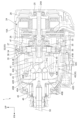
- FIG. 1 is a vertical sectional view showing an impact tool according to an embodiment of the present invention.
- FIG. 2 is an enlarged vertical cross-sectional view of an upper portion of the impact tool shown in FIG. 1 .
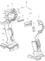
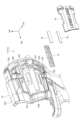
- 2 is a perspective view showing a left housing unit of the housing shown in FIG. 1, as viewed diagonally from the front left.
- FIG. 4 is an exploded perspective view of the housing unit shown in FIG. 3 .
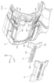
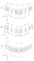
- 5 is an enlarged perspective view of the inner panel and the outer panel shown in FIG. 4. 4 is a side view showing an upper housing portion of the housing unit shown in FIG. 3 as viewed from the left side.
- FIG. 6 is a side view showing an upper housing portion of the housing unit shown in FIG. 3 as viewed from the left side.
- (A) is a cross-sectional view of the middle portion of the upper housing part in the fore-and-aft direction as viewed from the rear side (cross-sectional view taken along line 7A-7A in FIG. 6)
- (B) is a cross-sectional view of the rear portion of the upper housing part as viewed from the rear side (cross-sectional view taken along line 7B-7B in FIG. 6)
- (C) is a cross-sectional view of the rear portion of the upper housing part as viewed from the rear side (cross-sectional view taken along line 7C-7C in FIG. 6).
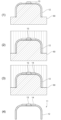
- 1A to 1C are explanatory views for explaining a first molding procedure of a housing unit.
- 11A to 11C are explanatory views for explaining a molding procedure 2 of the housing unit.
- FIG. 13 is a side view showing an upper housing portion of a housing unit according to a first modified example, as viewed from the left side.
- FIG. 10 ) and (B) is a cross-sectional view of the rear part of the upper housing part shown in FIG. 10 as viewed from the top side (cross-sectional view of line 11B-11B in FIG. 10 ).
- 11 is an exploded perspective view showing a state in which the outer panel and the inner panel shown in FIG. 10 are disassembled from a housing main body.
- FIG. 11 is an exploded perspective view showing a state in which an outer panel, an inner panel, and a magnet are disassembled from a housing main body in a housing unit of a second modified example.
- FIGS. 6A and 6B are cross-sectional views of the upper housing part in the housing unit of variant example 3, where (A) is a cross-sectional view seen from the rear side of the middle part of the front-to-rear direction of the upper housing part shown in Figure 6 (cross-sectional view taken along line 7A-7A in Figure 6), (B) is a cross-sectional view seen from the rear side of the rear part of the upper housing part shown in Figure 6 (cross-sectional view taken along line 7B-7B in Figure 6), and (C) is a cross-sectional view seen from the rear side of the rear part of the upper housing part shown in Figure 6 (cross-sectional view taken along line 7C-7C in Figure 6).
- the impact tool 1 as a work machine according to this embodiment, with reference to the drawings.
- the arrows UP, FR, and LH shown as appropriate in the drawings indicate the upper side, front side, and left side of the impact tool 1, respectively.
- the up-down, front-back, and left-right directions when used, they refer to the up-down, front-back, and left-right directions of the impact tool 1, unless otherwise specified.
- the impact tool 1 is configured as an electric tool that applies a rotational force and an impact force to a tip tool 50, such as a driver bit, attached to the front end of the impact tool 1 to perform fastening processing, etc.
- the impact tool 1 includes a housing 10 that forms the outer shell of the impact tool 1, a motor 24 housed in the housing 10, and a driving force transmission mechanism 30 that transmits the driving force of the motor 24 to the tip tool 50.
- a driving force transmission mechanism 30 that transmits the driving force of the motor 24 to the tip tool 50.
- the housing 10 is formed in a hollow, roughly I-shape when viewed from the left-right direction.
- the housing 10 includes an upper housing portion 10A as a body portion that forms the upper end of the housing 10 and extends in the front-to-rear direction, a handle portion 10B that extends downward from the middle portion of the upper housing portion 10A in the front-to-rear direction, and a lower housing portion 10C that forms the lower end of the housing 10.
- a trigger 20 is provided at the upper end of the handle portion 10B, and the trigger 20 protrudes forward from the handle portion 10B and can be pulled rearward.
- a switch mechanism 21 is provided on the handle portion 10B behind the trigger 20. The switch mechanism 21 has a switch (not shown), and pulling the trigger 20 switches the switch from off to on.
- a controller 22 is provided in the lower housing portion 10C.
- the switch of the switch mechanism 21 is electrically connected to the controller 22.
- a battery 23 is detachably attached to the lower housing portion 10C. The battery 23 is electrically connected to the controller 22, and supplies power to a motor 24, which will be described later. Details of the components of the housing 10 will be described later.
- the motor 24 is housed in the rear end of the upper housing part 10A and is electrically connected to the controller 22.
- the motor 24 has a drive shaft 24A whose axial direction is the front-rear direction.
- the rear end of the drive shaft 24A is rotatably supported by a first motor bearing 25 fixed to the housing 10.
- the front end portion of the drive shaft 24A is rotatably supported by a second motor bearing 26, which is fixed to a gear case 27 housed in the upper housing part 10A.
- the gear case 27 is formed in a stepped cylindrical shape whose axial direction is the front-rear direction, and the second motor bearing 26 is fitted into the approximate center of the gear case 27.
- the front end of the drive shaft 24A is disposed in the gear case 27, protruding forward from the second motor bearing 26.
- a fan 28 is provided on the rear end portion of the drive shaft 24A so as to be able to rotate integrally therewith.
- the driving force transmission mechanism 30 includes a rotary impact mechanism 40 that applies a rotational force and an impact force to the tip tool 50, and a speed reduction mechanism 32 that reduces the rotational force of the motor 24 and transmits it to the rotary impact mechanism 40.
- the reduction mechanism 32 is configured as a planetary gear mechanism and is disposed within the gear case 27. Specifically, the reduction mechanism 32 includes a sun gear 33 fixed to the front end of the drive shaft 24A of the motor 24, a ring-shaped ring gear 34 provided radially outside the sun gear 33, and a plurality of idle gears 35 (three in this embodiment) provided between the sun gear 33 and the ring gear 34.
- the ring gear 34 is held in the gear case 27 via a damper, and internal teeth are formed on the inner peripheral surface of the ring gear 34.
- the idle gear 35 is supported by a needle roller 36 provided on the carrier portion 41B of the spindle 41 so as to be rotatable with the front-to-rear direction as the axial direction.
- the idle gear 35 is also meshed with the internal teeth of the sun gear 33 and the ring gear 34.
- the rotary impact mechanism 40 includes a spindle 41, a hammer 42, and an anvil 45 as a tool holder.
- the spindle 41 has a spindle shaft 41A as a substantially cylindrical shaft portion with the axial direction being the front-to-rear direction, and the spindle shaft 41A is arranged coaxially with the drive shaft 24A of the motor 24.
- the sun gear 33 described above is inserted into the rear end portion of the spindle shaft 41A, and the rear end portion of the spindle shaft 41A is rotatably supported by a bearing 47 provided in the gear case 27.
- a carrier portion 41B extending radially outward from the spindle shaft 41A is provided on the rear end side portion of the outer periphery of the spindle shaft 41A, and the idle gear 35 described above is rotatably provided on the carrier portion 41B.
- a pair of spindle cam grooves 41C are formed on the outer peripheral surface of the front part of the spindle shaft 41A.
- the pair of spindle cam grooves 41C extend in a generally V-shape when viewed from the radial outside of the spindle shaft 41A.
- the spindle cam groove 41C is formed in a generally semicircular shape that is open to the radial outside of the spindle shaft 41A.
- a steel ball 43 is inserted in the front end of the spindle cam groove 41C so that it can roll.
- the hammer 42 is formed in a generally cylindrical shape with its axial direction extending in the front-to-rear direction, and an insertion hole 42A penetrates the center of the hammer 42 in the front-to-rear direction.
- the front part of the spindle 41 is inserted into the insertion hole 42A, and the hammer 42 is rotatably supported by the spindle 41.
- a pair of hammer cam grooves 42B are formed on the inner peripheral surface of the insertion hole 42A of the hammer 42.
- the hammer cam groove 42B extends along the circumferential direction of the hammer 42 when viewed from the front side, and is open to the front side.
- the rear end of the hammer cam groove 42B is formed in a roughly V-shape that is open to the front side when viewed from the radial inside of the hammer 42.
- the pair of hammer cam grooves 42B are arranged 180 degrees apart in the circumferential direction of the hammer 42.
- a steel ball 43 is inserted into the hammer cam groove 42B so as to be able to roll, and is located at the rear end of the hammer cam groove 42B.
- the rear surface of the hammer 42 is formed with a receiving groove 42C that is open to the rear side at the radial middle part.
- the receiving groove 42C extends along the circumferential direction of the hammer 42 and is formed around the entire circumferential direction of the hammer 42.
- the receiving groove 42C receives a hammer spring 44 configured as a compression spring, and the hammer 42 is biased forward by the hammer spring 44.
- the steel ball 43 is held in the front end of the spindle cam groove 41C and the rear end of the hammer cam groove 42B, and the hammer 42 and the spindle 41 are connected so that they can rotate together.
- Multiple hammer claws 42D are integrally provided on the front surface (one axial end surface) of the hammer 42.
- the thickness direction of the hammer claws 42D is the front-to-rear direction, and the hammer claws 42D are formed in a roughly sector-shaped block shape that protrudes radially inward of the hammer 42 when viewed from the front, and protrude forward from the hammer 42.
- the hammer claws 42D are arranged at equal intervals (every 120 degrees) around the circumference of the hammer 42.
- the anvil 45 is formed in a generally stepped cylindrical shape that opens to the front, and is disposed in front of the hammer 42. Specifically, a connecting shaft 45A having a smaller diameter than the other portions is formed at the rear end of the anvil 45, and the connecting shaft 45A is rotatably inserted into the front end of the spindle shaft 41A. The longitudinal middle portion of the anvil 45 is rotatably held by a sleeve 46 that is held at the front end of the upper housing portion 10A. The tip tool 50 is attached from the front side inside the anvil 45 so that it cannot move relative to the anvil 45.
- the anvil claws 45B are provided on the outer periphery of the rear end portion of the anvil 45.
- the anvil claws 45B are formed in a generally rectangular plate shape with the thickness direction being in the front-to-rear direction, and protrude radially outward from the anvil 45.
- the anvil claws 45B are arranged at equal intervals (every 120 degrees) around the circumference of the anvil 45, and are arranged between the hammer claws 42D of the hammer 42. In other words, when viewed from the front, the hammer claws 42D and the anvil claws 45B are arranged alternately around the circumference of the hammer 42.
- the housing 10 has a pair of left and right housing units 11 (only the left housing unit 11 is shown in FIG. 3), and the housing 10 is formed by assembling the pair of housing units 11 together. Below, the configuration of the housing units 11 will be explained using the left housing unit 11.
- the housing unit 11 is composed of a housing body 12 as a first housing, an inner plate 13 as a third housing, an outer plate 14 as a second housing, and a protective cover portion 15.
- the housing body 12 constitutes the framework of the housing unit 11 and is made of a resin material. That is, the housing body 12 constitutes the upper housing portion 10A, the handle portion 10B, and the lower housing portion 10C of the housing 10.
- the upper end portion of the housing body 12 (the portion constituting the upper housing portion 10A) is formed with a first recess 12A (see Figures 4 and 7(A)) for arranging the inner plate 13 and the outer plate 14 described later.
- the first recess 12A is formed in a generally rectangular recessed shape that is open to the left and has a longitudinal direction in the front-rear direction.
- the bottom surface of the first recess 12A is formed with a second recess 12B (see Figures 4 and 7(A)) at the middle portion in the vertical direction.
- the second recess 12B is formed in a generally rectangular recessed shape that is open to the left and has a longitudinal direction in the front-rear direction.
- the rear end portion of the first recess 12A is formed with an opening 12C (see Figures 4 and 7(B)) at the vertical outer side of the second recess 12B.
- the opening 12C is formed as a roughly rectangular hole with the vertical direction as the longitudinal direction.
- a pair of upper and lower body side air vents 12D are formed through the rear end of the housing body 12 on the vertical outside of the first recess 12A. That is, four body side air vents 12D are formed through the housing body 12.
- the body side air vents 12D are formed as approximately elongated holes with the longitudinal direction being the front-to-rear direction, and the front-to-rear length of the body side air vent 12D on the vertical outside is set shorter than the front-to-rear length of the body side air vent 12D on the vertical inside.
- the body side air vent 12D is positioned vertically outside the opening 12C, and the body side air vent 12D and the opening 12C are aligned vertically.
- the inner plate 13 is configured as a member for decorating the housing body 12.
- the inner plate 13 is formed from a metal material, a resin material, or the like, and is formed in a color different from the housing body 12.
- the inner plate 13 has an inner base portion 13A as a base portion and a mark portion 13B.
- the inner base portion 13A is formed in a substantially rectangular plate shape with the plate thickness direction being in the left-right direction and the longitudinal direction being in the front-rear direction.
- the outer shape of the inner base portion 13A corresponds to the outer shape of the second recess 12B of the housing body 12, and the inner base portion 13A is disposed within the second recess 12B and is formed integrally with the housing body 12 and the outer plate 14 described later (see FIG. 7(A)).
- the mark portion 13B is composed of letters, figures, symbols, etc., and protrudes to the left from the inner base portion 13A.
- the mark portion 13B is a character string of multiple alphabetical letters arranged in the front-to-back direction, and is written as "LOGOLOGO.” If the mark portion 13B contains an alphabetical letter with a closed hollow portion therein, such as the letter "O,” the hollow portion penetrates the inner base portion 13A. In this case, a slit portion 13C penetrating in the vertical direction is formed in the inner base portion 13A to the right of the letter, and the slit portion 13C is formed so as to bite into the right end portion of the mark portion 13B.
- the outer plate 14, like the inner plate 13, is configured as a member for decorating the housing body 12.
- the outer plate 14 is formed from a metal material, a resin material, or the like, and is formed in a color different from the housing body 12 and the inner plate 13.
- the outer plate 14 is formed from a metal material, it is set to be formed from a material that has higher mechanical strength (tensile strength, etc.) and thermal conductivity than the housing body 12.
- the outer plate 14 is formed in a generally rectangular plate shape with the plate thickness direction being the left-right direction and the longitudinal direction being the front-rear direction.
- the outer shape of the outer plate 14 corresponds to the outer shape of the first recess 12A of the housing body 12, and the outer plate 14 is disposed inside the first recess 12A and is formed integrally with the housing body 12 and the inner plate 13 (see FIG. 7(A)).
- the inner plate 13 is embedded in the outer plate 14 with the surface (left surface) of the mark portion 13B exposed so as to be visible. More specifically, the inner plate 13 is embedded in the outer plate 14 with the tip portion (left end portion) of the mark portion 13B protruding from the surface of the outer plate 14.
- the outer plate 14 is provided with a hole-shaped cutout 14A for locating the mark portion 13B, which penetrates the outer plate 14 in the left-right direction.
- a hole corresponding to the shape of the mark portion 13B is formed in the outer plate 14.
- the mark portion 13B contains an alphabetic character with a closed hollow portion such as the letter "O”
- a filled portion 14B corresponding to the hollow portion is formed inside the cutout 14A corresponding to this character.
- This filled portion 14B is connected to the outer plate 14 by a pair of upper and lower bridge portions 14C extending from the filled portion 14B to both sides in the up-down direction, and the bridge portion 14C is located one step lower to the right than the surface of the outer plate 14.
- the bridge portion 14C is disposed within the slit portion 13C of the outer plate 14 and is integrally formed with the inner plate 13 (see FIG. 7B).
- a pair of upper and lower ventilation cylinders 14D are formed on the vertical outside of the cutout portion 14A.
- the ventilation cylinders 14D are formed in a substantially rectangular tube shape, protrude from the outer plate 14 to the right, and are disposed within the opening 12C (see Figs. 7B and 7C).
- the inside of the ventilation cylinders 14D is a plate-side ventilation hole 14E as a ventilation hole.
- the plate-side ventilation hole 14E penetrates in the left-right direction, and the inside and outside of the housing 10 are connected by the plate-side ventilation hole 14E.
- the plate-side ventilation hole 14E and the main body-side ventilation hole 12D are located on the left-right outside of the motor 24, and airflow is taken into the housing 10 from the plate-side ventilation hole 14E and the main body-side ventilation hole 12D when the fan 28 rotates.
- the protective cover part 15 is made of an elastic material such as an elastomer.
- the protective cover part 15 is integrally formed on the surface of the housing main body 12 by two-color molding.
- the protective cover part 15 is formed over almost the entire housing main body 12 in the vertical direction, except for the outer plate 14 and the main body side ventilation hole 12D of the housing main body 12.
- molding procedure 1 of the housing unit 11 In molding procedure 1 of the housing unit 11, the housing main body 12 molded from a resin material and the inner plate 13 molded from a resin material or a metal material are prepared.
- the protective cover part 15 is integrally formed with the housing main body 12 by two-color molding. Then, the housing main body 12, the inner plate 13, and the outer plate 14 are integrally molded by insert molding.
- the mold 60 is opened, and the housing body 12 and the inner plate 13 are set in the core of the mold 60 (first step, see state (1) in FIG. 8).
- the mold 60 is clamped (see state (2) in FIG. 8).
- molten resin material is injected into the mold 60 to integrally mold the outer plate 14, the housing body 12, and the inner plate 13 (second step, see state (3) in FIG. 8). This forms the housing unit 11.
- the mold 60 is opened, and the housing unit 11 is removed from the mold 60 (see state (4) in FIG. 8).
- molding procedure 2 of the housing unit 11 the inner plate 13 and the outer plate 14 are prepared, and the inner plate 13 and the outer plate 14 are integrally molded by insert molding. Specifically, one of the inner plate 13 and the outer plate 14 is set in a molding die (not shown), and molten resin material is injected into the molding die to mold the other of the inner plate 13 and the outer plate 14, and to integrally mold the inner plate 13 and the outer plate 14. Note that the material of one of the inner plate 13 and the outer plate 14 set in the molding die is not limited, and is made of a material such as stone, wood, resin, or metal.
- the integrally formed inner plate 13 and outer plate 14 are molded with the housing body 12 by insert molding.
- the mold 62 is opened, and the inner plate 13 and outer plate 14 are set in the core of the mold 62 (first step, see state (1) in FIG. 9).
- the mold 62 is clamped (see state (2) in FIG. 9).
- molten resin material is injected into the mold 62 to integrally mold the housing body 12 with the inner plate 13 and outer plate 14 (second step, see state (3) in FIG. 9).
- the protective cover portion 15 is formed on the housing body 12 by two-color molding. This forms the housing unit 11.
- the housing unit 11 is removed from the two-color mold (see state (4) in FIG. 9).
- the housing unit 11 which is a component of the housing 10, is configured to include the housing main body 12 that constitutes the skeleton of the housing unit 11, and the inner plate 13 and the outer plate 14 that are configured as separate members from the housing main body 12.
- the outer plate 14 is formed integrally with the housing main body 12 in a state where it is exposed from the surface of the housing main body 12, and the inner plate 13 is formed integrally with the housing main body 12 and the outer plate 14 in a state where a part of it is exposed from the surface of the outer plate 14.
- the housing main body 12 can be decorated with the inner plate 13 and the outer plate 14 while the housing main body 12, the inner plate 13, and the outer plate 14 are formed integrally by insert molding.
- the housing main body 12 can be decorated while reducing the number of work steps. Therefore, the design of the impact tool 1 can be improved while suppressing an increase in cost.
- the outer plate 14 is constructed in a different color from the housing body 12, and the inner plate 13 is constructed in a different color from the housing body 12 and the outer plate 14.
- the outer plate 14 and the exposed portion of the inner plate 13 from the outer plate 14 can be effectively emphasized.
- the outer plate 14 when the outer plate 14 is made of a metal material, the outer plate 14 is made of a material that has high mechanical strength or thermal conductivity relative to the housing body 12. Therefore, the outer plate 14 can function as a reinforcing member for the housing body 12 while also functioning as a heat dissipation section. This makes it possible to increase the rigidity of the housing unit 11 and improve the heat dissipation of the housing unit 11. This improves the functionality of the housing unit 11. In addition, the housing body 12 and the outer plate 14 can be given different textures. This further improves the design of the impact tool 1.
- the housing main body 12 is also configured to include a handle portion 10B and an upper housing portion 10A provided above the handle portion 10B, and an inner plate 13 and an outer plate 14 are provided on the upper housing portion 10A.
- This allows the inner plate 13 and the outer plate 14 to be provided on the housing main body 12 while preventing the hand of the operator gripping the handle portion 10B from interfering with the inner plate 13 and the outer plate 14.
- the design of the impact tool 1 can be improved while ensuring the gripping performance of the housing 10.
- the outer plate 14 has plate-side ventilation holes 14E formed through it in the left-right direction, and the inside and outside of the housing unit 11 are connected by the plate-side ventilation holes 14E. This allows the outer plate 14, which is a decorative member, to pass airflow for cooling mechanical components such as the motor 24 inside the housing 10. This improves the functionality of the housing unit 11.
- the inner plate 13 is positioned so as to overlap with the plate-side ventilation holes 14E in the front-rear direction.
- the plate-side ventilation holes 14E are provided on both the top and bottom sides of the rear end of the inner plate 13. Therefore, compared to a structure in which the plate-side ventilation holes 14E and the inner plate 13 are offset in the front-rear direction, the inner plate 13 can be provided in the upper housing part 10A while preventing the upper housing part 10A from becoming larger in the front-rear direction.
- the inner plate 13 is composed of an inner base portion 13A and a mark portion 13B that protrudes outward in the plate thickness direction from the inner base portion 13A.
- the inner plate 13 is embedded in the outer plate 14 with the tip of the mark portion 13B protruding from the surface of the outer plate 14. This allows the mark portion 13B to be exposed three-dimensionally within the outer plate 14. This effectively improves the design of the impact tool 1.
- the outer plate 14 also has a cutout portion 14A, and the mark portion 13B of the inner plate 13 is disposed inside the cutout portion 14A of the outer plate 14.
- a filled portion 14B is disposed inside the cutout portion 14A, and the filled portion 14B is connected to the outer plate 14 by a bridge portion 14C.
- the housing body 12, inner plate 13, and outer plate 14 are molded integrally by insert molding. This reduces the number of molding steps for insert molding and allows the housing body 12, inner plate 13, and outer plate 14 to be formed integrally.
- the integrally formed inner plate 13 and outer plate 14 are integrally molded with the housing body 12 by insert molding.
- modification 1 of housing unit 11 Next, modification 1 of housing unit 11 will be described. As shown in Figs. 10 to 12, in modification 1, the vent cylinder portion 14D (plate side vent hole 14E) is omitted in the outer plate 14. In addition, a pair of upper and lower cover portions 13D are formed at the rear end of the inner plate 13, and the cover portions 13D extend outward in the vertical direction from the rear end of the inner plate 13. The cover portions 13D cover the entire opening 12C from the outside in the plate thickness direction while maintaining a state in which the inside of the opening 12C of the housing main body 12 is in communication with the outside of the housing unit 11. Specifically, the outer periphery of the cover portion 13D is disposed with a predetermined gap G1 on the outside in the plate thickness direction of the housing main body 12 relative to the edge portion 12C1 of the opening 12C.
- an outer plate 14 is provided on the surface of the cover portion 13D, and the outer plate 14 makes the cover portion 13D invisible from the surface side.
- the outer periphery of the cover portion 13D is surrounded by a protective cover portion 15 with a predetermined gap G2.
- the inside of the opening 12C communicates with the outside of the housing unit 11 through gaps G1 and G2 (see Figures 11 (A) and (B)).
- the cover portion 13D of the inner plate 13 covers the entire opening 12C from the outside in the plate thickness direction, and the outer periphery of the cover portion 13D is arranged with a predetermined gap G1 on the outside in the plate thickness direction of the housing body 12 relative to the edge portion 12C1 of the opening 12C. That is, the cover portion 13D of the inner plate 13 covers the opening 12C from the outside in the plate thickness direction while maintaining a communication state between the inside of the opening 12C of the housing body 12 and the outside of the housing unit 11. In other words, the opening 12C can be covered from the outside in the plate thickness direction of the housing body 12 while ensuring the ventilation function of the opening 12C. This ensures the cooling of mechanical components such as the motor 24, while improving the waterproofness and dustproofness of the impact tool 1. Therefore, the functionality of the housing unit 11 can be improved.
- the outer periphery of the cover portion 13D is surrounded by the protective cover portion 15 with a predetermined gap G2 therebetween.
- This allows a labyrinth structure consisting of the gaps G1 and G2 to be provided between the cover portion 13D and the housing main body 12. This effectively improves the waterproofness and dustproofness of the impact tool 1. It also improves the functionality of the housing unit 11.
- modification 2 of the housing unit 11 As shown in FIG. 13, in modification 2, a pair of upper and lower third recesses 12E are provided on the bottom surface of the first recess 12A of the housing main body 12, and the third recesses 12E are arranged on both sides of the second recess 12B in the up-down direction. Also, in modification 3, the housing unit 11 has a pair of magnets 16. The magnets 16 are formed in a substantially rectangular plate shape with the plate thickness direction in the left-right direction and the longitudinal direction in the front-rear direction. The magnets 16 are arranged in the third recesses 12E, are formed integrally with the housing main body 12 and the outer plate 14, and are embedded in the housing unit 11.
- the screws used in the fastening process can be magnetized on the surface of the outer plate 14. This improves the operability of the impact tool 1. It also improves the functionality of the housing unit 11.
- the magnet 16 is embedded in the housing unit 11, but the material embedded in the housing unit 11 is not limited to this.
- an insulating plate filled with gas may be embedded in the housing unit 11.
- the inner plate 13 is molded from a hard material such as a hard resin material or a metal material that is harder than the resin material that constitutes the outer plate 14, and the molded inner plate 13 is extended from the outer surface of the outer plate 14 to the inner surface of the outer plate 14 so as to fill the cutout portion 14A of the outer plate 14, and the outer base portion 13A that protrudes inward from the inner surface of the outer plate 14 supports the outer periphery of the driving force transmission mechanism 30.
- the driving force transmission mechanism 30 is formed from a hard material such as a metal material that is harder than the resin material that constitutes the outer plate 14.
- the driving force transmission mechanism 30 allows the driving force transmission mechanism 30 to be firmly supported, and the wear resistance of the housing unit 11 is improved. Furthermore, if the inner plate 13 is molded from a soft material such as an elastomer that is harder than the resin material that constitutes the outer plate 14, the driving force transmission mechanism 30 can be suppressed from vibrating. This improves the functionality of the housing unit 11. In this case, the outer periphery of the drive force transmission mechanism 30 may be supported only by the inner base part 13A, or the outer periphery of the hammer case may be supported by both the inner base part 13A and the housing main body 12.
- the inner plate 13 is molded from a hard material such as a hard resin material or a metal material having a higher hardness than the resin material constituting the outer plate 14, and the molded inner plate 13 is extended from the outer surface of the outer plate 14 to the inner surface of the outer plate 14 so as to fill the cutout portion 14A of the outer plate 14, and the outer periphery of the motor 24 is supported by the inner base portion 13A protruding inward from the inner surface of the outer plate 14.
- the motor 24 is formed from a hard material such as a metal material having a higher hardness than the resin material constituting the outer plate 14. This allows the motor 24 to be firmly supported and improves the wear resistance of the housing unit 11.
- the motor 24 can be suppressed from vibrating. Therefore, the functionality of the housing unit 11 can be improved.
- the outer periphery of the motor 24 may be supported only by the inner base part 13A, or the outer periphery of the motor 24 may be supported by both the inner base part 13A and the housing main body 12.
- the outer plate 14 is an example of a resin housing
- the inner plate 13 is an example of a support member
- the drive force transmission mechanism 30 and the motor 24 are examples of supported members
- the cutout part 14A is an example of a through hole
- the inner base part 13A is an example of a support part.
Landscapes
- Engineering & Computer Science (AREA)
- Mechanical Engineering (AREA)
- Manufacturing & Machinery (AREA)
- Portable Power Tools In General (AREA)
- Casings For Electric Apparatus (AREA)
Abstract
コストアップを抑制しつつ意匠性を向上する。インパクト工具1におけるハウジングユニット11は、ハウジングユニット11の骨格を構成するハウジング本体12と、ハウジング本体12とは別部材で構成されたインナプレート13及びアウタプレート14と、を含んで構成されている。アウタプレート14は、ハウジング本体12の表面から露出した状態で、ハウジング本体12に一体に形成され、インナプレート13は、一部がアウタプレート14の表面から露出した状態で、ハウジング本体12及びアウタプレート14に一体に形成されている。これにより、ハウジング本体12、インナプレート13、及びアウタプレート14を一体に形成しつつ、インナプレート13及びアウタプレート14によってハウジング本体12を加飾することができる。したがって、コストアップを抑制しつつインパクト工具1の意匠性を向上することができる。
Description
本発明は、ハウジングユニット、作業機、及びハウジングユニットの製造方法に関するものである。
下記特許文献1に記載のインパクトドライバ(作業機)では、インパクトドライバの外郭がハウジングにて構成されており、ハウジングは、2色成形にて形成されている。具体的には、インパクトドライバの骨格を構成する樹脂層が射出成形され、エラストマ等の弾性材にて構成された保護層が、樹脂層の表面上に形成される。また、ハウジングの表面には、飾り用プレートが設けられており、飾り用プレートは、樹脂層と保護層とを跨るように、ハウジングに貼り付けられている。これにより、保護層が連続して形成されるようになり、金型におけるゲート数を減少することができる。
しかしながら、上記ハウジングでは、以下に示す点において改善の余地がある。すなわち、飾り用プレートをハウジングに設けることで、インパクトドライバの意匠性等を向上できるものの、飾りプレートを、2色成形されたハウジングに貼着することで、ハウジングをユニット化している。このため、作業工数の増加等の要因で、ユニット化されたハウジングのコストアップを招く可能性がある。このため、インパクトドライバ等の作業機では、コストアップを抑制しつつ意匠性を向上できる構成にすることが望ましい。
本発明の第1の目的は、上記事実を考慮して、コストアップを抑制しつつ意匠性を向上できるハウジングユニット、作業機、及びハウジングユニットの製造方法を提供することを目的とするにある。また本発明の第2の目的は、機能性の高いハウジングユニット、作業機、及びハウジングユニットの製造方法を提供することある。
本発明の1又はそれ以上の実施形態は、作業機の外郭を構成するハウジングユニットであって、前記ハウジングユニットの骨格を構成する第1ハウジングと、前記第1ハウジングとは別部材で構成され、少なくとも一部が前記第1ハウジングの表面から露出した状態で前記第1ハウジングと一体に形成された第2ハウジングと、前記第2ハウジングとは別部材で構成され、少なくとも一部が前記第2ハウジングの表面から露出した状態で前記第1ハウジング及び第2ハウジングと一体に形成された第3ハウジングと、を備えたハウジングユニットである。
本発明の1又はそれ以上の実施形態は、前記第1ハウジングと前記第2ハウジングとが異なる色で構成され、前記第2ハウジングと前記第3ハウジングとが異なる色で構成されているハウジングユニットである。
本発明の1又はそれ以上の実施形態は、前記第2ハウジングは、前記第1ハウジングに対して機械的強度又は熱伝導性が高い材料で構成されているハウジングユニットである。
本発明の1又はそれ以上の実施形態は、前記第1ハウジングが樹脂材にて構成され、前記第2ハウジングが金属材にて構成されているハウジングユニットである。
本発明の1又はそれ以上の実施形態は、前記第1ハウジングは、作業者が把持するハンドル部と、前記作業機のモータを覆う胴体部と、を含んで構成され、前記第2ハウジング及び前記第3ハウジングが前記胴体部に設けられているハウジングユニットである。
本発明の1又はそれ以上の実施形態は、前記第2ハウジングには、通気孔が形成されており、前記通気孔によって前記ハウジングユニットの内部と外部とが連通しているハウジングユニットである。
本発明の1又はそれ以上の実施形態は、前記胴体部は、所定方向に延在されており、所定方向において第3ハウジングが前記通気孔と重なる位置に配置されているハウジングユニットである。
本発明の1又はそれ以上の実施形態は、前記胴体部には、開口部が板厚方向に貫通形成されており、前記第3ハウジングは、カバー部を有しており、前記カバー部は、前記開口部の全体を前記第1ハウジングの板厚方向外側から覆うと共に、前記カバー部の一部が前記開口部の縁部に対して前記板厚方向外側に離間して配置されているハウジングユニットである。
本発明の1又はそれ以上の実施形態は、前記第1ハウジングの表面には、弾性材で構成された保護カバー部が一体に形成されており、前記保護カバー部が、前記カバー部の外周部を、隙間を空けて囲んでいるハウジングユニットである。
本発明の1又はそれ以上の実施形態は、前記第3ハウジングは、ベース部と、前記ベース部から前記第3ハウジングの表面側へ突出するマーク部と、を含んで構成されており、前記第3ハウジングは、前記マーク部の先端部が前記第2ハウジングの表面から突出した状態で、前記第2ハウジングに埋設されているハウジングユニットである。
本発明の1又はそれ以上の実施形態は、前記第2ハウジングは、前記マーク部を内部に配置し、前記マーク部の側面と一体に形成された孔状の抜き部と、前記抜き部の内側に配置され、前記マーク部の側面と一体に形成された中埋め部と、前記第2ハウジングと中埋め部とを連結すると共に、前記第2ハウジングの表面よりも一段下がった位置に配置されたブリッジ部と、を含んで構成されているハウジングユニットである。
本発明の1又はそれ以上の実施形態は、前記第2ハウジングが前記第1ハウジングの板厚方向外側に設けられており、前記第1ハウジングと前記第2ハウジングとの間には、マグネット又は断熱部材が埋設されているハウジングユニットである。本発明の1又はそれ以上の実施形態は、作業機の外郭を構成するハウジングユニットであって、樹脂材で構成された樹脂製ハウジングと、前記ハウジングユニットの内側に位置し、前記樹脂製ハウジングよりも硬度の高い硬質材で構成された被支持部材と、前記第1ハウジングよりも硬度の高い硬質材で構成され、前記樹脂製ハウジングと一体に形成され、前記被支持部材を支持するよう構成された支持部材と、を有し、前記樹脂製ハウジングは前記樹脂製ハウジングの外側表面から内側表面まで延びる貫通穴を有し、前記支持部材は前記貫通穴を埋めるように前記樹脂製ハウジングの外側表面から内側表面まで延びており、前記支持部材は前記樹脂製ハウジングの内側表面より内側に突出した支持部を有し、前記支持部が前記被支持部材と接触し、前記被支持部材を支持するよう構成された、ハウジングユニットである。
本発明の1又はそれ以上の実施形態は、上記構成のハウジングユニットと、前記ハウジングユニットに収容されたモータと、先端工具を保持すると共に、前記モータの駆動によって作動する先端工具保持部と、を備えた作業機である。
本発明の1又はそれ以上の実施形態は、上記構成のハウジングユニットの製造方法であって、前記第1ハウジング及び前記第3ハウジングを成形型の内部にセットする第1工程と、前記成形型の内部に溶融樹脂材料を射出して、前記第2ハウジングを前記第1ハウジング及び前記第3ハウジングに一体に成形する第2工程と、を備えたハウジングユニットの製造方法である。
本発明の1又はそれ以上の実施形態は、上記構成のハウジングユニットの製造方法であって、一体形成された前記第2ハウジング及び前記第3ハウジングを成形型の内部にセットする第1工程と、前記成形型の内部に溶融樹脂材料を射出して、前記第1ハウジングを前記第2ハウジング及び前記第3ハウジングに一体に成形する第2工程と、を備えたハウジングユニットの製造方法である。
本発明の1又はそれ以上の実施形態によれば、コストアップを抑制しつつ意匠性を向上できるハウジングユニット、作業機、及びハウジングユニットの製造方法を提供することができる。また本発明の1又はそれ以上の実施形態によれば、機能性の高いハウジングユニット、作業機、及びハウジングユニットの製造方法を提供することができる。コストアップを抑制しつつ意匠性を向上できる。
以下、図面を用いて、本実施形態に係る作業機としてのインパクト工具1について説明する。なお、図面において適宜示される矢印UP、矢印FR、矢印LHは、それぞれインパクト工具1の上側、前側、左側を示している。以下の説明において、上下、前後、左右の方向を用いて説明するときには、特に断りのない限り、インパクト工具1の上下方向、前後方向、左右方向を示すものとする。
図1及び図2に示されるように、インパクト工具1は、インパクト工具1の前端部に取付けられるドライバビット等の先端工具50に回転力及び打撃力を付与して、締付加工等を行う電動工具として構成されている。
インパクト工具1は、インパクト工具1の外郭を構成するハウジング10と、ハウジング10に収容されたモータ24と、モータ24の駆動力を先端工具50に伝達する駆動力伝達機構30と、を含んで構成されている。以下、インパクト工具1の各構成について説明する。
(ハウジング10について) ハウジング10は、左右方向から見て、中空の略I字形状に形成されている。具体的には、ハウジング10は、ハウジング10の上端部を構成し且つ前後方向に延在された胴体部としてのアッパハウジング部10Aと、アッパハウジング部10Aの前後方向中間部から下側へ延出されたハンドル部10Bと、ハウジング10の下端部を構成するロアハウジング部10Cと、を含んで構成されている。
ハンドル部10Bの上端部には、トリガ20が設けられており、トリガ20は、ハンドル部10Bから前側へ突出すると共に、後側へ引き操作可能に構成されている。ハンドル部10Bには、トリガ20の後側において、スイッチ機構21が設けられている。スイッチ機構21は、図示しないスイッチを有しており、トリガ20が引き操作されることで、スイッチがオフからオンに切替る。
ロアハウジング部10Cには、コントローラ22が設けられている。コントローラ22には、スイッチ機構21のスイッチが電気的に接続されている。ロアハウジング部10Cには、バッテリ23が着脱可能に装着されている。バッテリ23は、コントローラ22に電気的に接続されており、バッテリ23によって、後述するモータ24に電力が供給される。ハウジング10の構成部品の詳細については、後述する。
(モータ24について) モータ24は、アッパハウジング部10Aの後端部に収容されると共に、コントローラ22に電気的に接続されている。モータ24は、前後方向を軸方向とする駆動軸24Aを有している。駆動軸24Aの後端部は、ハウジング10に固定された第1モータ軸受25によって回転可能に支持されている。一方、駆動軸24Aの前端側部分は、第2モータ軸受26によって回転可能に支持されており、第2モータ軸受26は、アッパハウジング部10A内に収容されたギヤケース27に固定されている。ギヤケース27は、前後方向を軸方向とする略段付円筒状に形成されており、第2モータ軸受26がギヤケース27の略中央部に嵌入されている。駆動軸24Aの前端部は、第2モータ軸受26よりも前側へ突出して、ギヤケース27内に配置されている。駆動軸24Aの後端側部分には、ファン28が一体回転可能に設けられている。
(駆動力伝達機構30について) 駆動力伝達機構30は、先端工具50に回転力及び打撃力を付与する回転打撃機構40と、モータ24の回転力を減速して回転打撃機構40に伝達する減速機構32と、を含んで構成されている。
(減速機構32について) 減速機構32は、遊星歯車機構として構成されて、ギヤケース27内に配置されている。具体的には、減速機構32は、モータ24の駆動軸24Aの前端部に固定されたサンギヤ33と、サンギヤ33の径方向外側に設けられたリング状のリングギヤ34と、サンギヤ33及びリングギヤ34の間に設けられた複数(本実施の形態では、3個)のアイドルギヤ35と、を含んで構成される。
リングギヤ34は、ダンパを介してギヤケース27に保持されており、リングギヤ34の内周面には内歯が形成されている。アイドルギヤ35は、スピンドル41のキャリア部41Bに設けられたニードルローラ36に前後方向を軸方向として回転可能に支持されている。また、アイドルギヤ35は、サンギヤ33及びリングギヤ34の内歯に噛合されている。これにより、サンギヤ33が回転すると、アイドルギヤ35がニードルローラ36の軸回りに自転しつつサンギヤ33の軸回りに公転して、スピンドル41が回転する構成になっている。
(回転打撃機構40について) 回転打撃機構40は、スピンドル41と、ハンマ42と、先端工具保持部としてのアンビル45と、を含んで構成されている。
スピンドル41は、前後方向を軸方向とする略円筒状の軸部としてのスピンドル軸41Aを有しており、スピンドル軸41Aが、モータ24の駆動軸24Aと同軸上に配置されている。具体的には、前述したサンギヤ33がスピンドル軸41Aの後端部内に挿入されており、スピンドル軸41Aの後端部が、ギヤケース27に設けられた軸受47によって、回転可能に支持されている。スピンドル軸41Aの外周部における後端側部には、スピンドル軸41Aから径方向外側へ延出したキャリア部41Bが設けられており、前述したアイドルギヤ35がキャリア部41Bに回転可能に設けられている。
スピンドル軸41Aの前部の外周面には、一対のスピンドルカム溝41Cが形成されている。一対のスピンドルカム溝41Cは、スピンドル軸41Aの径方向外側から見て、略V字形状に延在されている。スピンドルカム溝41Cは、その長手方向から見た断面視で、スピンドル軸41Aの径方向外側へ開放された略半円状に形成されている。スピンドルカム溝41Cの前端部内には、鋼球43が転動可能に挿入されている。
ハンマ42は、前後方向を軸方向とする略円筒状に形成されており、ハンマ42の中心部には、挿通孔42Aが前後方向に貫通している。スピンドル41の前部が、挿通孔42Aに挿入されて、ハンマ42がスピンドル41に回転可能に支持されている。
ハンマ42の挿通孔42Aの内周面には、一対のハンマカム溝42Bが形成されている。ハンマカム溝42Bは、前側から見てハンマ42の周方向に沿って延在すると共に、前方側へ開放されている。また、ハンマカム溝42Bの後端部は、ハンマ42の径方向内側から見て、前側へ開放された略V字形状に形成されている。一対のハンマカム溝42Bは、ハンマ42の周方向に180度離間して配置されている。そして、鋼球43が、ハンマカム溝42B内に転動可能に挿入されると共に、ハンマカム溝42Bの後端部に位置している。
ハンマ42の後面には、径方向中間部において、後側へ開放された収容溝部42Cが形成されている。収容溝部42Cは、ハンマ42の周方向に沿って延在されると共にハンマ42の周方向全周に亘って形成されている。そして、収容溝部42Cには、圧縮スプリングとして構成されたハンマスプリング44が収容されており、ハンマスプリング44によってハンマ42が前側に付勢している。これにより、鋼球43がスピンドルカム溝41Cの前端部及びハンマカム溝42Bの後端部内に保持されて、ハンマ42及びスピンドル41が、一体回転可能に連結されている。一方、回転打撃機構40の作動時には、鋼球43が、スピンドルカム溝41C及びハンマカム溝42B内を転動して、ハンマ42がスピンドル41に対して相対回転すると共に前後方向に相対移動する構成になっている。なお、ハンマスプリング44の後端部が、スピンドル41とハンマ42との間に配置された係止プレート48によって係止されている。
ハンマ42の前面(軸方向一方側端面)には、複数(本実施の形態では、3箇所)のハンマ爪42Dが一体に設けられている。ハンマ爪42Dは、前後方向を厚み方向とし、正面視でハンマ42の径方向内側へ凸となる略扇形ブロック状に形成されて、ハンマ42から前側へ突出している。ハンマ爪42Dは、ハンマ42の周方向に等間隔(120度毎)に配置されている。
アンビル45は、前側へ開放された略段付き円筒状に形成されて、ハンマ42の前側に配置されている。具体的には、アンビル45の後端部には、他の部分よりも小径の連結軸45Aが形成されており、連結軸45Aがスピンドル軸41Aの前端部に回転可能に挿入されている。アンビル45の長手方向中間部は、アッパハウジング部10Aの前端部に保持されたスリーブ46によって回転可能に保持されている。そして、先端工具50がアンビル45の内部に前側から相対移動不能に取付けられる。
アンビル45の後端側部分の外周部には、3箇所のアンビル爪45Bが設けられている。アンビル爪45Bは、前後方向を厚み方向とする略矩形プレート状に形成されて、アンビル45の径方向外側へ突出している。アンビル爪45Bは、アンビル45の周方向に等間隔(120度毎)に配置されると共に、ハンマ42のハンマ爪42Dの間に配置されている。すなわち、正面視で、ハンマ爪42Dとアンビル爪45Bとがハンマ42の周方向に交互に配置されている。
そして、ハンマ42の回転時には、ハンマ爪42Dの側面が、回転方向において隣り合うアンビル爪45Bの側面に当接し、ハンマ爪42Dとアンビル爪45Bとがハンマ42の周方向に係合する。これにより、ハンマ42からアンビル45に回転力が付与されて、アンビル45が先端工具50と共に回転する構成になっている。また、先端工具50を回転させるための回転力(トルク)が所定値を超えるときには、ハンマ爪42Dがアンビル爪45Bを乗り越えるように、ハンマ42がアンビル45に対して相対回転して、ハンマ42からアンビル45に打撃力が付与されるようになっている。
(ハウジング10の構成部品について) 図3に示されるように、ハウジング10は、左右一対のハウジングユニット11を有しており(図3では、左側のハウジングユニット11のみが図示されている)、一対のハウジングユニット11を互いに組付けることで、ハウジング10が形成されている。以下、左側のハウジングユニット11を用いて、ハウジングユニット11の構成について説明する。
図3~図7に示されるように、ハウジングユニット11は、第1ハウジングとしてのハウジング本体12と、第3ハウジングとしてのインナプレート13と、第2ハウジングとしてのアウタプレート14と、保護カバー部15と、を含んで構成されている。
ハウジング本体12は、ハウジングユニット11の骨格を構成しており、樹脂材によって形成されている。すなわち、ハウジング本体12は、ハウジング10のアッパハウジング部10A、ハンドル部10B、及びロアハウジング部10Cを構成している。ハウジング本体12の上端部(アッパハウジング部10Aを構成する部分)には、後述するインナプレート13及びアウタプレート14を配置するための第1凹部12A(図4及び図7(A)参照)が形成されている。第1凹部12Aは、左側へ開放され且つ前後方向を長手方向とする略矩形凹状に形成されている。第1凹部12Aの底面には、上下方向中間部において、第2凹部12B(図4及び図7(A)参照)が形成されている。第2凹部12Bは、左側へ開放され且つ前後方向を長手方向とする略矩形凹状に形成されている。第1凹部12Aの後端部には、第2凹部12Bの上下方向外側において、開口部12C(図4及び図7(B)参照)がそれぞれ貫通形成されている。開口部12Cは、上下方向を長手方向とする略矩形孔状に形成されている。
ハウジング本体12の後端部には、第1凹部12Aの上下方向外側において、上下一対の本体側通気孔12Dが貫通形成されている。すなわち、ハウジング本体12には、4箇所の本体側通気孔12Dが貫通形成されている。本体側通気孔12Dは、前後方向を長手方向とする略長孔状に形成されており、上下方向外側の本体側通気孔12Dの前後長が、上下方向内側の本体側通気孔12Dの前後長よりも短く設定されている。本体側通気孔12Dは、開口部12Cの上下方向外側に配置されており、本体側通気孔12Dと開口部12Cとが上下方向に並んでいる。
インナプレート13は、ハウジング本体12を加飾するための部材として構成されている。インナプレート13は、金属材や樹脂材等にて形成されると共に、ハウジング本体12とは異なる色で形成されている。インナプレート13は、ベース部としてのインナベース部13A及びマーク部13Bを有している。インナベース部13Aは、左右方向を板厚方向とし且つ前後方向を長手方向とする略矩形板状に形成されている。インナベース部13Aの外形は、ハウジング本体12の第2凹部12Bの外形に対応しており、インナベース部13Aが、第2凹部12B内に配置されて、ハウジング本体12及び後述するアウタプレート14と一体に形成されている(図7(A)参照)。
図5に示されるように、マーク部13Bは、文字、図形、記号等によって構成されており、インナベース部13Aから左側へ突出している。本実施の形態では、マーク部13Bが、複数のアルファベット文字を前後方向に並べた文字列であり、「LOGOLOGO」と表記されている。また、「O」文字のような、文字中に閉じた中空部があるアルファベット文字がマーク部13Bにある場合には、中空部がインナベース部13Aを貫通している。また、この場合には、上下方向に貫通するスリット部13Cが、当該文字の右側のインナベース部13Aに形成されており、スリット部13Cは、マーク部13Bの右端部に食い込むように形成されている。
アウタプレート14は、インナプレート13と同様に、ハウジング本体12を加飾するための部材として構成されている。アウタプレート14は、金属材や樹脂材等にて形成されると共に、ハウジング本体12及びインナプレート13とは異なる色で形成されている。ここで、アウタプレート14が金属材にて形成される場合には、機械的強度(引張強さ等)及び熱伝導率がハウジング本体12よりも高い材料でアウタプレート14が形成される設定になっている。
アウタプレート14は、左右方向を板厚方向とし且つ前後方向を長手方向とする略矩形板状に形成されている。アウタプレート14の外形は、ハウジング本体12の第1凹部12Aの外形に対応しており、アウタプレート14が、第1凹部12Aの内部に配置されて、ハウジング本体12及びインナプレート13と一体に形成されている(図7(A)参照)。具体的には、マーク部13Bの表面(左面)を視認可能に露出させた状態で、インナプレート13がアウタプレート14に埋設されている。より詳しくは、マーク部13Bの先端部(左端部)が、アウタプレート14の表面から突出した状態で、インナプレート13がアウタプレート14に埋設されている。
このため、アウタプレート14とインナプレート13とを分離した状態(アウタプレート14の単体状態)では、アウタプレート14において、マーク部13Bを配置するための孔状の抜き部14Aが、左右方向に貫通形成されるようになる。つまり、アウタプレート14の単体状態では、マーク部13Bの形状に対応する孔部がアウタプレート14に形成される。また、上述のように、「O」文字のような、文字中に閉じた中空部があるアルファベット文字がマーク部13Bにある場合には、この文字に対応する抜き部14Aの内側に、中空部に対応する中埋め部14Bが形成される。この中埋め部14Bは、中埋め部14Bから上下方向両側へ延出された上下一対のブリッジ部14Cによって、アウタプレート14と連結されており、ブリッジ部14Cは、アウタプレート14の表面よりも右側に一段下がった位置に配置されている。そして、インナプレート13のアウタプレート14との一体形成状態では、ブリッジ部14Cが、アウタプレート14のスリット部13C内に配置されて、インナプレート13と一体に形成されている(図7(B)参照)。
アウタプレート14の後端部には、抜き部14Aの上下方向外側において、上下一対の通気筒部14Dが形成されている、通気筒部14Dは、略矩形筒状に形成されて、アウタプレート14から右側へ突出して、開口部12C内に配置されている(図7(B)及び(C)参照)。通気筒部14Dの内部は、通気孔としてのプレート側通気孔14Eとされている。プレート側通気孔14Eは左右方向に貫通しており、プレート側通気孔14Eによってハウジング10の内部と外部とが連通している。プレート側通気孔14E及び本体側通気孔12Dは、モータ24の左右方向外側に位置しており、ファン28が回転することで、プレート側通気孔14E及び本体側通気孔12Dからハウジング10内に空気流が取り込まれるようになっている。
保護カバー部15は、エラストマ等の弾性材にて形成されている。保護カバー部15は、2色成形によってハウジング本体12の表面に一体に形成されている。保護カバー部15は、アウタプレート14及びハウジング本体12の本体側通気孔12Dを除く部分において、ハウジング本体12の上下方向の略全体に亘って形成されている。
(作用効果) 次に、ハウジングユニット11の成形手順を説明しつつ、本実施形態の作用及び効果について説明する。
(成形手順1について) ハウジングユニット11の成形手順1では、樹脂材にて成形されたハウジング本体12と、樹脂材又は金属材で成形されたインナプレート13と、を準備する。なお、ハウジング本体12では、2色成形によって、保護カバー部15がハウジング本体12に一体に形成されている。そして、インサート成形によって、ハウジング本体12及びインナプレート13とアウタプレート14と一体成形する。
具体的には、成形型60を開いて、ハウジング本体12及びインナプレート13を成形型60のコアにセットする(第1工程であり、図8の(1)の状態を参照)。次に、成形型60を型締めする(図8の(2)の状態を参照)。そして、溶融された樹脂材を成形型60内に射出して、アウタプレート14とハウジング本体12及びインナプレート13とを一体成形する(第2工程であり、図8の(3)の状態を参照)。これにより、ハウジングユニット11が形成される。その後に、成形型60を開いて、ハウジングユニット11を成形型60から取り出す(図8の(4)の状態を参照)。
(成形手順2について) ハウジングユニット11の成形手順2では、インナプレート13及びアウタプレート14を準備して、インサート成形によってインナプレート13とアウタプレート14とを一体成形する。具体的には、インナプレート13及びアウタプレート14の一方を成形型(図示省略)にセットし、溶融された樹脂材料を当該成形型内に射出して、インナプレート13及びアウタプレート14の他方を成形すると共に、インナプレート13とアウタプレート14とを一体成形する。なお、成形型にセットされるインナプレート13及びアウタプレート14の一方は、材質が限定されず、石材、木材、樹脂材又は金属材といった材質にて構成されている。
次に、インサート成形によって、一体に形成されたインナプレート13及びアウタプレート14とハウジング本体12と一体成形する。具体的には、成形型62を開いて、インナプレート13及びアウタプレート14を成形型62のコアにセットする(第1工程であり、図9の(1)の状態を参照)。次に、成形型62を型締めする(図9の(2)の状態を参照)。そして、溶融された樹脂材を成形型62内に射出して、ハウジング本体12とインナプレート13及びアウタプレート14とを一体成形する(第2工程であり、図9の(3)の状態を参照)。また、ハウジング本体12の成形後には、2色成形によって、保護カバー部15をハウジング本体12に形成する。これにより、ハウジングユニット11が形成される。そして、保護カバー部15の成形後、2色成形型からハウジングユニット11を取り出す(図9の(4)の状態を参照)。
このように、ハウジング10の構成部品であるハウジングユニット11は、ハウジングユニット11の骨格を構成するハウジング本体12と、ハウジング本体12とは別部材で構成されたインナプレート13及びアウタプレート14と、を含んで構成されている。アウタプレート14は、ハウジング本体12の表面から露出した状態で、ハウジング本体12に一体に形成され、インナプレート13は、一部がアウタプレート14の表面から露出した状態で、ハウジング本体12及びアウタプレート14に一体に形成されている。これにより、上述のように、インサート成形によって、ハウジング本体12、インナプレート13、及びアウタプレート14を一体に形成しつつ、インナプレート13及びアウタプレート14によってハウジング本体12を加飾することができる。すなわち、例えば、インナプレート13及びアウタプレート14をハウジング本体12に貼り付ける構造と比べて、作業工数を低減しつつ、ハウジング本体12を加飾することができる。したがって、コストアップを抑制しつつインパクト工具1の意匠性を向上することができる。
また、アウタプレート14がハウジング本体12とは異なる色で構成され、インナプレート13がハウジング本体12及びアウタプレート14と異なる色で構成されている。これにより、アウタプレート14をハウジング本体12に対して強調させつつ、インナプレート13のアウタプレート14からの露出部をアウタプレート14に対して強調させることができる。また、例えば、アウタプレート14の色とハウジング本体12の色とを、補色の関係となる色に設定し、インナプレート13の色とアウタプレート14の色とを、補色の関係となる色に設定することで、アウタプレート14、及びインナプレート13のアウタプレート14からの露出部を、効果的に強調させることができる。
また、アウタプレート14が金属材で形成される場合には、アウタプレート14が、ハウジング本体12に対して機械的強度又は熱伝導性が高い材料で構成される。このため、アウタプレート14を、ハウジング本体12の補強部材として機能させつつ、放熱部としても機能させることができる。これにより、ハウジングユニット11の剛性を高くすることができると共に、ハウジングユニット11の放熱性を向上することができる。よってハウジングユニット11の機能性を向上することができる。また、ハウジング本体12とアウタプレート14とを異なる質感にすることができる。これにより、インパクト工具1の意匠性をより一層向上することができる。
また、ハウジング本体12は、ハンドル部10Bと、ハンドル部10Bの上側に設けられたアッパハウジング部10Aと、を含んで構成されており、インナプレート13及びアウタプレート14がアッパハウジング部10Aに設けられている。これにより、ハンドル部10Bを把持する作業者の手がインナプレート13及びアウタプレート14に干渉することを抑制しつつ、インナプレート13及びアウタプレート14をハウジング本体12に設けることができる。すなわち、ハウジング10における把持性能を確保しつつ、インパクト工具1の意匠性を向上することができる。
また、アウタプレート14には、プレート側通気孔14Eが左右方向に貫通形成されており、プレート側通気孔14Eによってハウジングユニット11の内部と外部とが連通している。これにより、加飾部材であるアウタプレート14を用いて、ハウジング10内のモータ24等の機構部品を冷却するための空気流を通過させることができる。よってハウジングユニット11の機能性を向上することができる。
また、前後方向においてインナプレート13がプレート側通気孔14Eと重なる位置に配置されている。具体的には、プレート側通気孔14Eがインナプレート13の後端部の上下方向両側に設けられている。このため、前後方向において、プレート側通気孔14Eとインナプレート13とをずらし配置する構造と比べて、アッパハウジング部10Aの前後方向の体格の大型化を抑制しつつ、インナプレート13をアッパハウジング部10Aに設けることができる。
また、インナプレート13は、インナベース部13Aと、インナベース部13Aから板厚方向外側へ突出したマーク部13Bと、を含んで構成されている。そして、マーク部13Bの先端部がアウタプレート14の表面から突出した状態で、インナプレート13がアウタプレート14に埋設されている。このため、アウタプレート14内をおいてマーク部13Bを立体的に露出させることができる。これにより、インパクト工具1の意匠性を効果的に向上することができる。
また、アウタプレート14は、抜き部14Aを有しており、インナプレート13のマーク部13Bが、アウタプレート14の抜き部14Aの内部に配置されている。また、抜き部14Aの内部には、中埋め部14Bが配置されており、ブリッジ部14Cによって中埋め部14Bがアウタプレート14に連結されている。これにより、「O」文字等のように閉じた中空部がマーク部13Bにある場合でも、中空部に対応する中埋め部14Bをアウタプレート14に連結して、アウタプレート14をインナプレート13と一体に形成することができる。これにより、マーク部13Bにおける意匠性を向上することができる。
また、ハウジングユニット11の成形手順1では、インサート成形によって、ハウジング本体12及びインナプレート13とアウタプレート14とを一体成形している。これにより、インサート成形の成形工程を少なくして、ハウジング本体12、インナプレート13、及びアウタプレート14を一体に形成することができる。
また、ハウジングユニット11の成形手順2では、一体に形成されたインナプレート13及びアウタプレート14と、ハウジング本体12と、をインサート成形によって一体成形している。これにより、例えば、用途に応じて、インナプレート13及びアウタプレート14の一方の材料を樹脂材や金属材等の何れかの材料に選択して、ハウジング本体12、インナプレート13、及びアウタプレート14を一体に形成することができる。
(ハウジングユニット11の変形例1) 次に、ハウジングユニット11の変形例1について説明する。図10~図12に示されるように、変形例1では、アウタプレート14において通気筒部14D(プレート側通気孔14E)が省略されている。また、インナプレート13の後端部には、上下一対のカバー部13Dが形成されており、カバー部13Dは、インナプレート13の後端部から上下方向外側へ延出している。カバー部13Dは、ハウジング本体12の開口部12Cの内部とハウジングユニット11の外部との連通状態を維持したまま、開口部12Cの全体を板厚方向外側から覆っている。具体的には、カバー部13Dの外周部が、開口部12Cの縁部12C1に対してハウジング本体12の板厚方向外側に所定の隙間G1を空けて配置されている。
また、カバー部13Dの表面には、アウタプレート14が設けられており、アウタプレート14によって、カバー部13Dが、表面側から視認不能になっている。また、カバー部13D部の外周部が、保護カバー部15によって、所定の隙間G2を空けて囲まれている。これにより、隙間G1及び隙間G2によって、開口部12Cの内部とハウジングユニット11の外部とが連通している(図11(A)及び(B)参照)。
そして、ハウジングユニット11の変形例1では、上述のように、インナプレート13のカバー部13Dが、開口部12Cの全体を板厚方向外側から覆うと共に、カバー部13Dの外周部が、開口部12Cの縁部12C1に対してハウジング本体12の板厚方向外側に所定の隙間G1を空けて配置されている。すなわち、インナプレート13のカバー部13Dが、ハウジング本体12の開口部12Cの内部とハウジングユニット11の外部との連通状態を維持したまま、開口部12Cを板厚方向外側から覆っている。つまり、開口部12Cの通気機能を確保したまま、開口部12Cをハウジング本体12の板厚方向外側から覆うことができる。これにより、モータ24等の機構部品に対する冷却性を確保しつつ、インパクト工具1の防水性及び防塵性を向上することができる。よってハウジングユニット11の機能性を向上することができる。
また、ハウジングユニット11の変形例1では、カバー部13Dの外周部が、所定の隙間G2を空けて保護カバー部15に囲まれている。これにより、隙間G1及び隙間G2によるラビリンス構造を、カバー部13Dとハウジング本体12との間に設けることができる。したがって、インパクト工具1の防水性及び防塵性を効果的に向上することができる。またハウジングユニット11の機能性を向上することができる。
(ハウジングユニット11の変形例2) 次に、ハウジングユニット11の変形例2について説明する。図13に示されるように、変形例2では、ハウジング本体12の第1凹部12Aの底面に、上下一対の第3凹部12Eが設けられており、第3凹部12Eは、第2凹部12Bの上下方向両側にそれぞれ配置されている。また、変形例3では、ハウジングユニット11が一対のマグネット16を有している。マグネット16は、左右方向を板厚方向とし前後方向を長手方向とする略矩形板状に形成されている。マグネット16は、第3凹部12Eに配置され、ハウジング本体12とアウタプレート14と一体に形成されて、ハウジングユニット11内に埋設されている。
これにより、ハウジングユニット11の変形例2では、例えば、締付加工に用いるネジをアウタプレート14の表面に着磁させることができる。これにより、インパクト工具1の作業性を向上することができる。またハウジングユニット11の機能性を向上することができる。
なお、変形例2では、マグネット16がハウジングユニット11に埋設されているが、ハウジングユニット11に埋設する部材はこれに限らない。例えば、図示は省略するが、ガスが注入された断熱プレートをハウジングユニット11に埋設してもよい。
(ハウジングユニット11の変形例3) 次に、ハウジングユニット11の変形例3について説明する。図14(A)に示されるように、変形例3では、アウタプレート14を構成する樹脂材よりも硬度の高い硬質樹脂材や金属材などの硬質材でインナプレート13を成形し、成形したインナプレート13をアウタプレート14の抜き部14Aを埋めるようにアウタプレート14の外側表面からアウタプレート14の内側表面まで延ばして、アウタプレート14の内側表面より内側に突出したインナベース部13Aで駆動力伝達機構30の外周を支持している。駆動力伝達機構30は、アウタプレート14を構成する樹脂材よりも硬度の高い金属材などの硬質材で形成されている。これにより強固に駆動力伝達機構30を支持することができるとともに、ハウジングユニット11の耐摩耗性が向上する。またインナプレート13をアウタプレート14を構成する樹脂材よりも硬度の低いエラストマ等の軟質材で成形した場合は、駆動力伝達機構30が振動するのを抑制することができる。よってハウジングユニット11の機能性を向上することができる。この際、インナベース部13Aのみで駆動力伝達機構30の外周を支持してもよいし、インナベース部13Aとハウジング本体12の両方でハンマケースの外周を支持してもよい。
また図14(C)に示されるように、変形例3では、アウタプレート14を構成する樹脂材よりも硬度の高い硬質樹脂材や金属材などの硬質材でインナプレート13を成形し、成形したインナプレート13をアウタプレート14の抜き部14Aを埋めるようにしてアウタプレート14の外側表面からアウタプレート14の内側表面まで延ばして、アウタプレート14の内側表面より内側に突出したインナベース部13Aでモータ24の外周を支持している。モータ24は、アウタプレート14を構成する樹脂材よりも硬度の高い金属材などの硬質材で形成されている。これにより強固にモータ24を支持することができるとともに、ハウジングユニット11の耐摩耗性が向上する。またインナプレート13をアウタプレート14を構成する樹脂材よりも硬度の低いエラストマ等の軟質材で成形した場合は、モータ24が振動するのを抑制することができる。よってハウジングユニット11の機能性を向上することができる。図14(C)において、インナベース部13Aのみでモータ24の外周を支持してもよいし、インナベース部13Aとハウジング本体12の両方でモータ24の外周を支持してもよい。アウタプレート14は樹脂製ハウジングの一例であり、インナプレート13は支持部材の一例であり、駆動力伝達機構30及びモータ24は被支持部材の一例であり、抜き部14Aは貫通穴の一例であり、インナベース部13Aは支持部の一例である。
1…インパクト工具(作業機)、10A…アッパハウジング部(胴体部)、10B…ハンドル部、11…ハウジングユニット、1112…ハウジング本体(第1ハウジング)、12C…開口部、13…インナプレート(第3ハウジング)、13A…インナベース部(ベース部)、13B…マーク部、13D…カバー部、14…アウタプレート(第2ハウジング)、14A…抜き部、14B…中埋め部、14C…ブリッジ部、14E…プレート側通気孔(通気孔)、15…保護カバー部、24…モータ、45…アンビル(先端工具保持部)、50…先端工具、60…成形型、62…成形型、G2…隙間
Claims (16)
- 作業機の外郭を構成するハウジングユニットであって、
前記ハウジングユニットの骨格を構成する第1ハウジングと、
前記第1ハウジングとは別部材で構成され、少なくとも一部が前記第1ハウジングの表面から露出した状態で前記第1ハウジングと一体に形成された第2ハウジングと、
前記第2ハウジングとは別部材で構成され、少なくとも一部が前記第2ハウジングの表面から露出した状態で前記第1ハウジング及び第2ハウジングと一体に形成された第3ハウジングと、
を備えたハウジングユニット。 - 前記第1ハウジングと前記第2ハウジングとが異なる色で構成され、前記第2ハウジングと前記第3ハウジングとが異なる色で構成されている請求項1に記載のハウジングユニット。
- 前記第2ハウジングは、前記第1ハウジングに対して機械的強度又は熱伝導性が高い材料で構成されている請求項1に記載のハウジングユニット。
- 前記第1ハウジングが樹脂材にて構成され、前記第2ハウジングが金属材にて構成されている請求項3に記載のハウジングユニット。
- 前記第1ハウジングは、
作業者が把持するハンドル部と、
前記作業機のモータを覆う胴体部と、
を含んで構成され、
前記第2ハウジング及び前記第3ハウジングが前記胴体部に設けられている請求項1に記載のハウジングユニット。 - 前記第2ハウジングには、通気孔が形成されており、前記通気孔によって前記ハウジングユニットの内部と外部とが連通している請求項5に記載のハウジングユニット。
- 前記胴体部は、所定方向に延在されており、所定方向において第3ハウジングが前記通気孔と重なる位置に配置されている請求項6に記載のハウジングユニット。
- 前記胴体部には、開口部が板厚方向に貫通形成されており、
前記第3ハウジングは、カバー部を有しており、前記カバー部は、前記開口部の全体を前記第1ハウジングの板厚方向外側から覆うと共に、前記カバー部の一部が前記開口部の縁部に対して前記板厚方向外側に離間して配置されている請求項5に記載のハウジングユニット。 - 前記第1ハウジングの表面には、弾性材で構成された保護カバー部が一体に形成されており、
前記保護カバー部が、前記カバー部の外周部を、隙間を空けて囲んでいる請求項8に記載のハウジングユニット。 - 前記第3ハウジングは、
ベース部と、
前記ベース部から前記第3ハウジングの表面側へ突出するマーク部と、
を含んで構成されており、
前記第3ハウジングは、前記マーク部の先端部が前記第2ハウジングの表面から突出した状態で、前記第2ハウジングに埋設されている請求項1に記載のハウジングユニット。 - 前記第2ハウジングは、
前記マーク部を内部に配置し、前記マーク部の側面と一体に形成された孔状の抜き部と、
前記抜き部の内側に配置され、前記マーク部の側面と一体に形成された中埋め部と、
前記第2ハウジングと中埋め部とを連結すると共に、前記第2ハウジングの表面よりも一段下がった位置に配置されたブリッジ部と、
を含んで構成されている請求項10に記載のハウジングユニット。 - 前記第2ハウジングが前記第1ハウジングの板厚方向外側に設けられており、
前記第1ハウジングと前記第2ハウジングとの間には、マグネット又は断熱部材が埋設されている請求項1に記載のハウジングユニット。 - 作業機の外郭を構成するハウジングユニットであって、
樹脂材で構成された樹脂製ハウジングと、
前記ハウジングユニットの内側に位置し、前記樹脂製ハウジングよりも硬度の高い硬質材で構成された被支持部材と、
前記第1ハウジングよりも硬度の高い硬質材で構成され、前記樹脂製ハウジングと一体に形成され、前記被支持部材を支持するよう構成された支持部材と、を有し、
前記樹脂製ハウジングは前記樹脂製ハウジングの外側表面から内側表面まで延びる貫通穴を有し、
前記支持部材は前記貫通穴を埋めるように前記樹脂製ハウジングの外側表面から内側表面まで延びており、前記支持部材は前記樹脂製ハウジングの内側表面より内側に突出した支持部を有し、前記支持部が前記被支持部材と接触し、前記被支持部材を支持するよう構成された、ハウジングユニット。 - 請求項1~請求項13の何れか1項に記載のハウジングユニットと、
前記ハウジングユニットに収容されたモータと、
先端工具を保持すると共に、前記モータの駆動によって作動する先端工具保持部と、
を備えた作業機。 - 請求項1に記載のハウジングユニットの製造方法であって、
前記第1ハウジング及び前記第3ハウジングを成形型の内部にセットする第1工程と、
前記成形型の内部に溶融樹脂材料を射出して、前記第2ハウジングを前記第1ハウジング及び前記第3ハウジングに一体に成形する第2工程と、
を備えたハウジングユニットの製造方法。 - 請求項1に記載のハウジングユニットの製造方法であって、
一体形成された前記第2ハウジング及び前記第3ハウジングを成形型の内部にセットする第1工程と、
前記成形型の内部に溶融樹脂材料を射出して、前記第1ハウジングを前記第2ハウジング及び前記第3ハウジングに一体に成形する第2工程と、
を備えたハウジングユニットの製造方法。
Priority Applications (2)
| Application Number | Priority Date | Filing Date | Title |
|---|---|---|---|
| CN202480043240.1A CN121398936A (zh) | 2023-06-30 | 2024-06-28 | 壳体单元、作业机以及壳体单元的制造方法 |
| JP2025530234A JPWO2025005244A1 (ja) | 2023-06-30 | 2024-06-28 |
Applications Claiming Priority (2)
| Application Number | Priority Date | Filing Date | Title |
|---|---|---|---|
| JP2023-107680 | 2023-06-30 | ||
| JP2023107680 | 2023-06-30 |
Publications (1)
| Publication Number | Publication Date |
|---|---|
| WO2025005244A1 true WO2025005244A1 (ja) | 2025-01-02 |
Family
ID=93939127
Family Applications (1)
| Application Number | Title | Priority Date | Filing Date |
|---|---|---|---|
| PCT/JP2024/023508 Ceased WO2025005244A1 (ja) | 2023-06-30 | 2024-06-28 | ハウジングユニット、作業機、及びハウジングユニットの製造方法 |
Country Status (3)
| Country | Link |
|---|---|
| JP (1) | JPWO2025005244A1 (ja) |
| CN (1) | CN121398936A (ja) |
| WO (1) | WO2025005244A1 (ja) |
Citations (5)
| Publication number | Priority date | Publication date | Assignee | Title |
|---|---|---|---|---|
| JP2017136666A (ja) * | 2016-02-04 | 2017-08-10 | 株式会社マキタ | 電動工具 |
| JP6615298B2 (ja) * | 2018-10-03 | 2019-12-04 | 株式会社マキタ | 動力工具 |
| JP7096032B2 (ja) * | 2018-03-28 | 2022-07-05 | 株式会社マキタ | マルチツール |
| JP2023061256A (ja) * | 2021-10-19 | 2023-05-01 | 株式会社マキタ | 動力工具 |
| JP7276492B2 (ja) * | 2019-10-31 | 2023-05-18 | 工機ホールディングス株式会社 | 電動作業機 |
-
2024
- 2024-06-28 JP JP2025530234A patent/JPWO2025005244A1/ja active Pending
- 2024-06-28 WO PCT/JP2024/023508 patent/WO2025005244A1/ja not_active Ceased
- 2024-06-28 CN CN202480043240.1A patent/CN121398936A/zh active Pending
Patent Citations (5)
| Publication number | Priority date | Publication date | Assignee | Title |
|---|---|---|---|---|
| JP2017136666A (ja) * | 2016-02-04 | 2017-08-10 | 株式会社マキタ | 電動工具 |
| JP7096032B2 (ja) * | 2018-03-28 | 2022-07-05 | 株式会社マキタ | マルチツール |
| JP6615298B2 (ja) * | 2018-10-03 | 2019-12-04 | 株式会社マキタ | 動力工具 |
| JP7276492B2 (ja) * | 2019-10-31 | 2023-05-18 | 工機ホールディングス株式会社 | 電動作業機 |
| JP2023061256A (ja) * | 2021-10-19 | 2023-05-01 | 株式会社マキタ | 動力工具 |
Also Published As
| Publication number | Publication date |
|---|---|
| JPWO2025005244A1 (ja) | 2025-01-02 |
| CN121398936A (zh) | 2026-01-23 |
Similar Documents
| Publication | Publication Date | Title |
|---|---|---|
| JP7398894B2 (ja) | 工具保持装置、及び電動作業機 | |
| JP2009083058A (ja) | 電動工具 | |
| CN101687318A (zh) | 电动工具 | |
| JP2014124751A (ja) | インパクト工具 | |
| JPH0957650A (ja) | ハンマードリル | |
| WO2020235614A1 (ja) | 操作入力装置及びボタン駆動ユニット | |
| CN1990331A (zh) | 车辆用锁止装置 | |
| WO2025005244A1 (ja) | ハウジングユニット、作業機、及びハウジングユニットの製造方法 | |
| CN102689334A (zh) | 电动工具 | |
| DE102021121505A1 (de) | Bohrwerkzeug | |
| JP2007295773A (ja) | Dcブラシレスモータ | |
| JP6957220B2 (ja) | 回転打撃工具 | |
| JP5413039B2 (ja) | 携帯用工具 | |
| JP5724381B2 (ja) | 携帯型作業機 | |
| JP6036320B2 (ja) | 携帯型作業機 | |
| JP2017144523A5 (ja) | ||
| JP7276492B2 (ja) | 電動作業機 | |
| JP2012257452A (ja) | Dcブラシレスモータ | |
| JP2023079884A (ja) | インパクトドライバ | |
| JP2009113131A (ja) | ソフトタッチ弾性層付工具 | |
| KR101364897B1 (ko) | 구동 장치, 폐쇄 시스템 및 이를 포함하는 자동차 | |
| JP4655655B2 (ja) | 電動工具 | |
| JP2009023024A (ja) | 携帯用工具 | |
| JP2011136384A (ja) | 手持ち式電動工具及びハウジングの製造方法 | |
| JP2023061296A (ja) | インパクト工具 |
Legal Events
| Date | Code | Title | Description |
|---|---|---|---|
| 121 | Ep: the epo has been informed by wipo that ep was designated in this application |
Ref document number: 24832102 Country of ref document: EP Kind code of ref document: A1 |
|
| ENP | Entry into the national phase |
Ref document number: 2025530234 Country of ref document: JP Kind code of ref document: A |
|
| WWE | Wipo information: entry into national phase |
Ref document number: 2025530234 Country of ref document: JP |
|
| NENP | Non-entry into the national phase |
Ref country code: DE |