WO2025005199A1 - 電子機器 - Google Patents
電子機器 Download PDFInfo
- Publication number
- WO2025005199A1 WO2025005199A1 PCT/JP2024/023412 JP2024023412W WO2025005199A1 WO 2025005199 A1 WO2025005199 A1 WO 2025005199A1 JP 2024023412 W JP2024023412 W JP 2024023412W WO 2025005199 A1 WO2025005199 A1 WO 2025005199A1
- Authority
- WO
- WIPO (PCT)
- Prior art keywords
- light
- diaphragm
- electronic device
- receiving element
- signal
- Prior art date
- Legal status (The legal status is an assumption and is not a legal conclusion. Google has not performed a legal analysis and makes no representation as to the accuracy of the status listed.)
- Ceased
Links
Images


































Classifications
-
- A—HUMAN NECESSITIES
- A61—MEDICAL OR VETERINARY SCIENCE; HYGIENE
- A61B—DIAGNOSIS; SURGERY; IDENTIFICATION
- A61B5/00—Measuring for diagnostic purposes; Identification of persons
- A61B5/103—Measuring devices for testing the shape, pattern, colour, size or movement of the body or parts thereof, for diagnostic purposes
- A61B5/11—Measuring movement of the entire body or parts thereof, e.g. head or hand tremor or mobility of a limb
- A61B5/1101—Detecting tremor
-
- A—HUMAN NECESSITIES
- A61—MEDICAL OR VETERINARY SCIENCE; HYGIENE
- A61B—DIAGNOSIS; SURGERY; IDENTIFICATION
- A61B7/00—Instruments for auscultation
- A61B7/02—Stethoscopes
-
- A—HUMAN NECESSITIES
- A61—MEDICAL OR VETERINARY SCIENCE; HYGIENE
- A61B—DIAGNOSIS; SURGERY; IDENTIFICATION
- A61B5/00—Measuring for diagnostic purposes; Identification of persons
-
- A—HUMAN NECESSITIES
- A61—MEDICAL OR VETERINARY SCIENCE; HYGIENE
- A61B—DIAGNOSIS; SURGERY; IDENTIFICATION
- A61B5/00—Measuring for diagnostic purposes; Identification of persons
- A61B5/0059—Measuring for diagnostic purposes; Identification of persons using light, e.g. diagnosis by transillumination, diascopy, fluorescence
-
- A—HUMAN NECESSITIES
- A61—MEDICAL OR VETERINARY SCIENCE; HYGIENE
- A61B—DIAGNOSIS; SURGERY; IDENTIFICATION
- A61B5/00—Measuring for diagnostic purposes; Identification of persons
- A61B5/74—Details of notification to user or communication with user or patient; User input means
- A61B5/7405—Details of notification to user or communication with user or patient; User input means using sound
-
- A—HUMAN NECESSITIES
- A61—MEDICAL OR VETERINARY SCIENCE; HYGIENE
- A61B—DIAGNOSIS; SURGERY; IDENTIFICATION
- A61B5/00—Measuring for diagnostic purposes; Identification of persons
- A61B5/74—Details of notification to user or communication with user or patient; User input means
- A61B5/742—Details of notification to user or communication with user or patient; User input means using visual displays
-
- A—HUMAN NECESSITIES
- A61—MEDICAL OR VETERINARY SCIENCE; HYGIENE
- A61B—DIAGNOSIS; SURGERY; IDENTIFICATION
- A61B5/00—Measuring for diagnostic purposes; Identification of persons
- A61B5/74—Details of notification to user or communication with user or patient; User input means
- A61B5/7475—User input or interface means, e.g. keyboard, pointing device, joystick
-
- A—HUMAN NECESSITIES
- A61—MEDICAL OR VETERINARY SCIENCE; HYGIENE
- A61B—DIAGNOSIS; SURGERY; IDENTIFICATION
- A61B7/00—Instruments for auscultation
- A61B7/02—Stethoscopes
- A61B7/04—Electric stethoscopes
-
- G—PHYSICS
- G01—MEASURING; TESTING
- G01B—MEASURING LENGTH, THICKNESS OR SIMILAR LINEAR DIMENSIONS; MEASURING ANGLES; MEASURING AREAS; MEASURING IRREGULARITIES OF SURFACES OR CONTOURS
- G01B11/00—Measuring arrangements characterised by the use of optical techniques
- G01B11/02—Measuring arrangements characterised by the use of optical techniques for measuring length, width or thickness
-
- G—PHYSICS
- G01—MEASURING; TESTING
- G01H—MEASUREMENT OF MECHANICAL VIBRATIONS OR ULTRASONIC, SONIC OR INFRASONIC WAVES
- G01H17/00—Measuring mechanical vibrations or ultrasonic, sonic or infrasonic waves, not provided for in the other groups of this subclass
-
- G—PHYSICS
- G01—MEASURING; TESTING
- G01H—MEASUREMENT OF MECHANICAL VIBRATIONS OR ULTRASONIC, SONIC OR INFRASONIC WAVES
- G01H3/00—Measuring characteristics of vibrations by using a detector in a fluid
- G01H3/04—Frequency
-
- G—PHYSICS
- G01—MEASURING; TESTING
- G01H—MEASUREMENT OF MECHANICAL VIBRATIONS OR ULTRASONIC, SONIC OR INFRASONIC WAVES
- G01H9/00—Measuring mechanical vibrations or ultrasonic, sonic or infrasonic waves by using radiation-sensitive means, e.g. optical means
-
- G—PHYSICS
- G10—MUSICAL INSTRUMENTS; ACOUSTICS
- G10K—SOUND-PRODUCING DEVICES; METHODS OR DEVICES FOR PROTECTING AGAINST, OR FOR DAMPING, NOISE OR OTHER ACOUSTIC WAVES IN GENERAL; ACOUSTICS NOT OTHERWISE PROVIDED FOR
- G10K9/00—Devices in which sound is produced by vibrating a diaphragm or analogous element, e.g. fog horns, vehicle hooters or buzzers
- G10K9/12—Devices in which sound is produced by vibrating a diaphragm or analogous element, e.g. fog horns, vehicle hooters or buzzers electrically operated
Definitions
- the present invention relates to electronic devices.
- Patent Document 1 proposes an electronic auscultation device that acquires living body sounds using a capacitive microphone.
- Patent Document 2 proposes an auscultation device that uses a vibration sensor in the acquisition section that acquires living body sounds.
- an auscultation device that detects vibrations of a living body using a vibration sensor as in Patent Document 2
- a certain pressure is applied as the vibration sensor is pressed against the surface of the living body, reducing the amount of displacement of the surface of the living body and worsening the S/N ratio.
- an electronic device includes a diaphragm that contacts an object to be measured, the diaphragm having a light reflecting portion on a surface of the diaphragm opposite to the contact surface that contacts the object to be measured, a light emitting diode, an aperture portion that narrows down the light emitted from the light emitting diode, a light receiving element having a light receiving surface that receives light that passes through the aperture portion and is specularly reflected by the light reflecting portion, an output means that outputs a signal corresponding to the light of a light irradiation area formed by the specularly reflected light that reaches the light receiving surface, and a housing that houses the light emitting diode, the aperture portion, and the light receiving element.
- the diaphragm together with the housing, forms part of the exterior of the electronic device, and is configured to elastically deform when pressed by a measured object that contacts the contact surface, and the boundary between the light-irradiated area on the light-receiving surface and the area other than the light-irradiated area, which is formed by the light narrowed by the narrowing section and specularly reflected by the light reflecting section, moves in response to the displacement of the contact surface due to the elastic deformation of the diaphragm, thereby changing the area of the light-irradiated area on the light-receiving surface and changing the output of the output means.
- the above embodiment allows the displacement of the object to be measured to be measured with high accuracy.
- FIG. 1 is a schematic diagram illustrating an example of the appearance of an electronic auscultation device according to a first embodiment
- 1 is a schematic diagram illustrating an example of the appearance of an electronic auscultation device according to a first embodiment
- FIG. 2 is a schematic diagram illustrating a configuration example of a chest piece according to the first embodiment
- FIG. 13 is a schematic diagram illustrating a modified example of the chest piece of the first embodiment.
- FIG. 13 is a schematic diagram illustrating a modified example of the chest piece of the first embodiment.
- 5A to 5C are schematic diagrams illustrating an example of the operation of the chest piece of the first embodiment.
- 5A to 5C are schematic diagrams illustrating an example of the operation of the chest piece of the first embodiment.
- 5A to 5C are schematic diagrams illustrating an example of movement of reflected light in the first embodiment.
- 5A to 5C are schematic diagrams illustrating an example of movement of reflected light in the first embodiment.
- 5A to 5C are schematic diagrams illustrating an example of movement of reflected light in the first embodiment.
- 5A to 5C are schematic diagrams illustrating an example of movement of reflected light in the first embodiment.
- 5A to 5C are schematic diagrams illustrating an example of movement of reflected light in the first embodiment.
- 5A to 5C are schematic diagrams illustrating an example of movement of reflected light in the first embodiment.
- FIG. 1 is a block diagram illustrating an example of the configuration of an electronic auscultation device according to a first embodiment.
- 5A to 5C are schematic diagrams illustrating an example of the operation of the chest piece of the first embodiment.
- 5A to 5C are schematic diagrams illustrating an example of the operation of the chest piece of the first embodiment.
- 5A to 5C are schematic diagrams illustrating an example of the operation of the chest piece of the first embodiment.
- 5A to 5C are schematic diagrams illustrating an example of the operation of the chest piece of the first embodiment.
- 5A and 5B are schematic diagrams illustrating an example of change in the light receiving range according to the first embodiment.
- FIG. 1 is a block diagram illustrating an example of the configuration of an electronic auscultation device according to a first embodiment.
- 5A to 5C are schematic diagrams illustrating an example of the operation of the chest piece of the first embodiment.
- 5A to 5C are schematic diagrams illustrating an example of the operation of the chest piece of the first embodiment.
- FIG. 13 is a schematic diagram illustrating a first modified example of the chest piece of the first embodiment.
- FIG. 13 is a schematic diagram illustrating a first modified example of the chest piece of the first embodiment.
- FIG. 13 is a schematic diagram illustrating a second modified example of the chest piece of the first embodiment.
- FIG. 13 is a schematic diagram illustrating a second modified example of the chest piece of the first embodiment.
- 13A and 13B are diagrams illustrating the relationship between the amount of displacement and the displacement signal in the second modified example.
- FIG. 13 is a schematic diagram illustrating a third modified example of the chest piece of the first embodiment.
- FIG. 13 is a schematic diagram illustrating a third modified example of the chest piece of the first embodiment.
- FIG. 13 is a schematic diagram illustrating a third modified example of the chest piece of the first embodiment.
- FIG. 11 is a block diagram illustrating an example of the configuration of an electronic auscultation device according to a second embodiment.
- FIG. 13 is a schematic diagram illustrating a configuration example of a chest piece according to a second embodiment.
- FIG. 13 is a schematic diagram illustrating a configuration example of a chest piece according to a second embodiment.
- FIG. 13 is a schematic diagram illustrating a configuration example of a chest piece according to a second embodiment.
- FIG. 13 is a schematic diagram illustrating a configuration example of a chest piece according to a second embodiment.
- FIG. 13 is a schematic diagram illustrating a configuration example of a chest piece according to a second embodiment.
- FIG. 13 is a schematic diagram illustrating a configuration example of a chest piece according to a second embodiment.
- FIG. 11 is a block diagram illustrating an example of the configuration of an electronic auscultation device according to a second embodiment.
- FIG. 13 is a schematic diagram illustrating a configuration example of a chest piece according to a second
- FIG. 13 is a schematic diagram illustrating a configuration example of a chest piece according to a second embodiment.
- FIG. 13 is a schematic diagram illustrating a configuration example of a chest piece according to a second embodiment.
- FIG. 13 is a schematic diagram illustrating a configuration example of a chest piece according to a second embodiment.
- FIG. 13 is a schematic diagram illustrating a configuration example of a chest piece according to a second embodiment.
- FIG. 13 is a schematic diagram illustrating a configuration example of a chest piece according to a second embodiment.
- FIG. 13 is a schematic diagram illustrating a configuration example of a chest piece according to a second embodiment.
- FIG. 13 is a schematic diagram illustrating a configuration example of a chest piece according to a second embodiment.
- FIG. 13 is a schematic diagram illustrating a configuration example of a chest piece according to a second embodiment.
- FIG. 13 is a schematic diagram illustrating a configuration example of a chest piece according to a second embodiment.
- FIG. 13 is a schematic diagram illustrating a configuration example of a chest piece according to a second embodiment.
- FIG. 13 is a schematic diagram illustrating a configuration example of a chest piece according to a second embodiment.
- FIG. 13 is a schematic diagram illustrating a configuration example of a chest piece according to a second embodiment.
- FIG. 13 is a schematic diagram illustrating a configuration example of a chest piece according to a second embodiment.
- FIG. 13 is a schematic diagram illustrating a modified example of the chest piece of the second embodiment.
- FIG. 13 is a schematic diagram illustrating a modified example of the chest piece of the second embodiment.
- FIG. 13 is a schematic diagram illustrating a modified example of the chest piece of the second embodiment.
- FIG. 13 is a schematic diagram illustrating a modified example of the chest piece of the second embodiment.
- FIG. 13 is a schematic diagram illustrating a modified example of the chest piece of the second embodiment.
- FIG. 13 is a schematic diagram illustrating a modified example of the chest piece of the second embodiment.
- FIG. 13 is a schematic diagram illustrating a modified example of the chest piece of the second embodiment.
- FIG. 13 is a schematic diagram illustrating a modified example of the chest piece of the second embodiment.
- FIG. 13 is a schematic diagram illustrating a modified example of the chest piece of the second embodiment.
- FIG. 13 is a schematic diagram illustrating a modified example of the chest piece of the second embodiment.
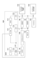
- FIG. 11 is a block diagram illustrating an example of a circuit configuration of an electronic auscultation device according to a second embodiment.
- FIG. 11 is a block diagram illustrating an example of a circuit configuration of an electronic auscultation device according to a second embodiment.
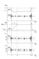
- FIG. 13 is a diagram for explaining the effect of an example of the circuit configuration of the electronic auscultation device according to the second embodiment.
- FIG. 13 is a diagram for explaining the effect of an example of the circuit configuration of the electronic auscultation device according to the second embodiment.
- FIG. 13 is a diagram for explaining the effect of an example of the circuit configuration of the electronic auscultation device according to the second embodiment.
- FIG. 13 is a diagram for explaining the effect of an example of the circuit configuration of the electronic auscultation device according to the second embodiment.
- FIG. 13 is a diagram for explaining the effect of an example of the circuit configuration of the electronic auscultation device according to the second embodiment.
- FIG. 13 is a diagram for explaining the effect of an example of the circuit configuration of the electronic auscultation device according to the second embodiment.
- FIG. 13 is a diagram for explaining the effect of an example of the circuit configuration of the electronic auscultation device according to the second embodiment.
- FIG. 13 is a diagram for explaining the effect of an example of the circuit configuration of the electronic auscultation device according to the second embodiment.
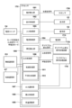
- FIG. 11 is a block diagram illustrating an example of the functional configuration of an electronic auscultation device according to a second embodiment.
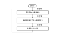
- FIG. 11 is a flowchart illustrating an example of the operation of the electronic auscultation device according to the second embodiment.
- FIG. 11 is a flowchart illustrating an example of the operation of the electronic auscultation device according to the second embodiment.
- FIG. 11 is a schematic diagram illustrating an example of the operation of the electronic auscultation device according to the second embodiment.
- FIG. 11 is a flowchart illustrating an example of the operation of the electronic auscultation device according to the second embodiment.
- FIG. 11 is a schematic diagram illustrating an example of the operation of the electronic auscultation device according to the second embodiment.
- FIG. 13 is a schematic diagram illustrating a display example of the electronic auscultation device according to the second embodiment.
- FIG. 13 is a schematic diagram illustrating a modified example of the electronic auscultation device of the second embodiment.
- FIG. 13 is a schematic diagram illustrating a modified example of the electronic auscultation device of the second embodiment.
- FIG. 13 is a schematic diagram illustrating a modified example of the electronic auscultation device of the second embodiment.
- FIG. 13 is a schematic diagram illustrating a modified example of the electronic auscultation device of the second embodiment.
- FIG. 13 is a schematic diagram illustrating a modified example of the electronic auscultation device of the second embodiment.
- FIG. 13 is a schematic diagram illustrating a modified example of the electronic auscultation device of the second embodiment.
- FIG. 13 is a schematic diagram illustrating a modified example of the electronic auscultation device of the second embodiment.
- FIG. 11 is a state transition diagram for explaining an example of state transition of the electronic auscultation device according to the second embodiment.
- FIG. 11 is a flow diagram illustrating an example of state transition of the electronic auscultation device according to the second embodiment.
- FIG. 11 is a flow diagram illustrating an example of state transition of the electronic auscultation device according to the second embodiment.
- 5 is a schematic diagram for explaining an example of the operation of the electronic auscultation device according to the second embodiment;
- FIG. 5 is a schematic diagram for explaining an example of the operation of the electronic auscultation device according to the second embodiment;
- FIG. 13 is a schematic diagram illustrating an example of the configuration of an electronic auscultation device according to a third embodiment.
- FIG. 11 is a state transition diagram for explaining an example of state transition of the electronic auscultation device according to the second embodiment.
- FIG. 11 is a flow diagram illustrating an example of state transition of the electronic auscultation device according to the second embodiment.
- FIG. 11 is a flow diagram illustrating an example of
- FIG. 13 is a schematic diagram illustrating an example of the configuration of an electronic auscultation device according to a third embodiment.
- FIG. 13 is a schematic diagram illustrating an example of the configuration of an electronic auscultation device according to a third embodiment.
- FIG. 13 is a schematic diagram illustrating an example of the configuration of an electronic auscultation device according to a third embodiment.
- FIG. 13 is a schematic diagram illustrating an example of the configuration of an electronic auscultation device according to a third embodiment.
- FIG. 13 is a schematic diagram illustrating an example of the configuration of an electronic auscultation device according to a third embodiment.
- FIG. 13 is a schematic diagram illustrating an example of the configuration of an electronic auscultation device according to a third embodiment.
- FIG. 13 is a schematic diagram illustrating an example of the configuration of an electronic auscultation device according to a third embodiment.
- FIG. 13 is a schematic diagram illustrating an example of the configuration of an electronic auscultation device according to a third embodiment.
- FIG. 13 is a schematic diagram illustrating an example of the configuration of an electronic auscultation device according to a third embodiment.
- FIG. 13 is a schematic diagram illustrating a modified example of the electronic auscultation device of the third embodiment.
- FIG. 13 is a schematic diagram illustrating a modified example of the electronic auscultation device of the third embodiment.
- FIG. 13 is a schematic diagram illustrating a modified example of the electronic auscultation device of the third embodiment.
- FIG. 13 is a schematic diagram illustrating an example of the configuration of an electronic auscultation device according to a fourth embodiment.
- FIG. 13 is a schematic diagram illustrating an example of the configuration of an electronic auscultation device according to a fourth embodiment.
- FIG. 13 is a schematic diagram illustrating an example of the configuration of an electronic auscultation device according to a fourth embodiment.
- FIG. 13 is a schematic diagram illustrating an example of the configuration of an electronic auscultation device according to a fourth embodiment.
- FIG. 13 is a schematic diagram illustrating an example of the configuration of an electronic auscultation device according to a fourth embodiment.
- FIG. 13 is a schematic diagram illustrating an example of the configuration of an electronic auscultation device according to a fourth embodiment.
- FIG. 13 is a schematic diagram illustrating an example of the configuration of an electronic auscultation device according to a fourth embodiment.
- FIG. 13 is a schematic diagram illustrating an example of the configuration of an electronic auscultation device according to a fourth embodiment.
- FIG. 13 is a schematic diagram illustrating an example of the configuration of an electronic auscultation device according to a fourth embodiment.
- FIG. 13 is a schematic diagram illustrating a modified example of the electronic auscultation device of the fourth embodiment.
- FIG. 13 is a schematic diagram illustrating a modified example of the electronic auscultation device of the fourth embodiment.
- FIG. 13 is a schematic diagram illustrating a modified example of the electronic auscultation device of the fourth embodiment.
- FIG. 13 is a schematic diagram illustrating a modified example of the electronic auscultation device of the fourth embodiment.
- FIG. 13 is a schematic diagram illustrating a modified example of the electronic auscultation device of the fourth embodiment.
- FIG. 13 is a schematic diagram illustrating a modified example of the electronic auscultation device of the fourth embodiment.
- FIG. 13 is a schematic diagram illustrating a modified example of the electronic auscultation device of the fourth embodiment.
- FIG. 13 is a schematic diagram illustrating a modified example of the electronic auscultation device of the fourth embodiment.
- FIG. 13 is a schematic diagram illustrating a modified example of the electronic auscultation device of the fourth embodiment.
- FIG. 13 is a schematic diagram illustrating a modified example of the electronic auscultation device of the fourth embodiment.
- FIG. 13 is a schematic diagram illustrating a modified example of the electronic auscultation device of the fourth embodiment.
- FIG. 13 is a schematic diagram illustrating a modified example of the electronic auscultation device of the fourth embodiment.
- FIG. 13 is a schematic diagram illustrating a modified example of the electronic auscultation device of the fourth embodiment.
- FIG. 13 is a schematic diagram illustrating a modified example of the electronic auscultation device of the fourth embodiment.
- FIG. 13 is a schematic diagram illustrating a modified example of the electronic auscultation device of the fourth embodiment.
- FIG. 13 is a schematic diagram illustrating a modified example of the electronic auscultation device of the fourth embodiment.
- FIG. 13 is a schematic diagram illustrating a modified example of the electronic auscultation device of the fourth embodiment.
- a coordinate system CS which is a three-dimensional Cartesian coordinate system having an x-axis, a y-axis, and a z-axis, may be attached to explain the directions.
- the positive direction of the z-axis may be expressed as the upper side
- the negative direction of the z-axis may be expressed as the lower side.
- Fig. 1A shows the appearance of the electronic auscultation device 100 when viewed from a certain direction
- the electronic auscultation device 100 is an electronic device used as a diagnostic tool for listening to the internal sounds of a living body such as a human or an animal.
- the electronic auscultation device 100 is mainly used to listen to heartbeat sounds and respiratory sounds.
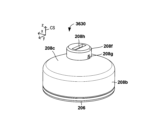
- the electronic auscultation device 100 has a chest piece 110 and a gripping portion 120.
- the chest piece 110 is a unit that is brought into contact with the surface of a living body, which is an example of a subject to be measured, during diagnosis using the electronic auscultation device 100, to measure minute vibrations (displacements) on the surface of the living body and capture biological sounds.
- the chest piece 110 detects minute displacements on the surface of the living body that it is in close contact with via a diaphragm 206, which will be described later. Therefore, the chest piece 110 can also be referred to as a displacement detection device or a diaphragm displacement detection device.
- the chest piece 110 is used to detect vibrations on the surface of the living body, it can also be referred to as a biological vibration detection device.
- the gripping part 120 is gripped by a user of the electronic auscultation device 100 (e.g., a doctor, nurse, or public health nurse) when the diaphragm 206 is brought into close contact with the surface of a living body.
- a user of the electronic auscultation device 100 e.g., a doctor, nurse, or public health nurse
- the gripping part 120 is rod-shaped as shown in Figs. 1A and 1B, and the chest piece 110 is attached to one end (the negative x-axis direction in Figs. 1A and 1B).
- the gripping part 120 is also called a handle, a grip, a handle, or the like.
- the gripping part 120 and the chest piece 110 are configured to be able to swing relative to each other, but the present invention is not limited to this, and may be fixed to the gripping part 120, or the chest piece 110 may also function as the gripping part.
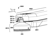
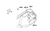
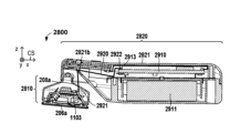
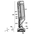
- the grip part 120 has a housing 121.
- the grip part 120 houses a battery and a circuit board inside the housing 121.
- the battery stores operating power for the electronic auscultation device 100.
- the circuit board has circuit elements for controlling the operation of the electronic auscultation device 100.
- the grip part 120 has a display unit 122, an operation unit 123, a power switch 124, and a connector 125 on the outer surface of the housing 121.
- the display unit 122 displays the state of the electronic auscultation device 100.
- the display unit 122 may include multiple indicators (four indicators in the example of FIG. 1A). Each indicator is composed of a light-emitting diode (LED).
- the multiple indicators include an indicator that indicates whether the power of the electronic auscultation device 100 is on or off.
- the multiple indicators also include an indicator that indicates the current operating mode of the electronic auscultation device 100.
- the multiple indicators also include an indicator that indicates whether the electronic auscultation device 100 is wirelessly connected to an external device.
- the multiple indicators also include an indicator that indicates whether the chest piece 110 is pressed against the surface of the living body. As shown in FIG.
- the display unit 122 is disposed near the chest piece 110, which is one end side in the x-axis direction, on the surface of the outer surface of the housing 121 opposite the chest piece 110.
- the vicinity of the chest piece 110 means that it is closer to the chest piece 110 than the center of the grip part 120.
- the operation unit 123 accepts operations from the user.
- the operation unit 123 includes multiple physical buttons (three buttons in the example of FIG. 1A) for accepting settings of the electronic auscultation device 100.
- the operation unit 123 includes volume adjustment buttons (volume up button 123a and volume down button 123b) for adjusting the volume of the sound output.
- volume adjustment button When the volume adjustment button is pressed, the electronic auscultation device 100 adjusts the gain of the signal output from the light receiving element 204 and adjusts the volume of the sound output through the earphones.
- the operation unit 123 includes a mode switching button 123c for switching the operation mode of the electronic auscultation device 100. When the mode switching button 123c is pressed, the operation mode is switched as described below.
- the mode switching button 123c accepts instructions from the user regarding the mode transition of the electronic auscultation device 100.
- the operation unit 123 may include a touch panel instead of multiple physical buttons.
- the display unit 122 and the operation unit 123 may be integrated into a touch screen.
- the operation unit 123 like the display unit 122, is arranged on the outer surface of the housing 121 opposite the chestpiece 110, near one end of the chestpiece 110 in the x-axis direction. This arrangement allows the user to operate the operation unit 123 (e.g., with their thumb) while holding the grip unit 120 while using the electronic auscultation device 100.
- the display unit 122 is also arranged in a position farther away from the center of the grip unit 120 in the x-axis direction than the operation unit 123. This arrangement allows the user to maintain visibility of the display unit 122 even when operating the operation unit 123 while using the electronic auscultation device 100.
- the power switch 124 is a switch that switches the power of the electronic auscultation device 100 on and off.
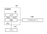
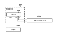
- the connector 125 is a connector for receiving a cable or a connector of an external device. Power is supplied from the external device to the battery included in the grip portion 120 through the connector 125.
- the power switch 124 may be provided on the chest piece 110 instead of the grip portion 120.
- the connector 125 may be provided on the chest piece 110 instead of the grip portion 120.
- the electronic auscultation device 100 may not include the connector 125. In this case, the electronic auscultation device 100 may have a wireless charging function and may be configured so that the battery is replaceable.
- the electronic stethoscope device 100 includes both the chest piece 110 and the gripping portion 120, but alternatively, the electronic stethoscope device 100 may include only the chest piece 110 and not include the gripping portion 120.
- FIG. 2A shows a configuration example of the chest piece 110
- the upper side of Fig. 2A shows a cross-sectional view of the chest piece 110
- the lower side of Fig. 2A shows a plan view of the chest piece 110.
- the plan view in order to clarify the positional relationship of the components, only the light emitting circuit board 203, the light receiving circuit board 205, the diaphragm 206, and the light reflecting portion 207 are shown.
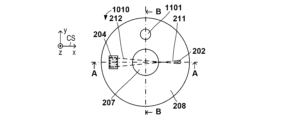
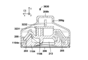
- the chest piece 110 has a holding member 201, a light emitting element 202, a light emitting circuit board 203, a light receiving element 204, a light receiving circuit board 205, a diaphragm 206, a light reflecting portion 207, and a housing 208.
- the housing 208 houses the holding member 201, the light emitting element 202, the light emitting circuit board 203, the light receiving element 204, the light receiving circuit board 205, and the light reflecting portion 207. Since the holding member 201 has the diaphragm portions 209 and 210, the housing 208 also houses the diaphragm portions 209 and 210 inside.
- the diaphragm 206 and the housing 208 form part of the exterior of the electronic stethoscope device 100.
- the components of the chest piece 110 described here are examples, and in addition to the components shown in FIG. 2A, the chest piece 110 may have a circuit board on which a circuit element for controlling the operation of the chest piece 110 is mounted.
- the light-emitting element 202 is a light source that emits light. Power is supplied to the light-emitting element 202 from a power source external to the chest piece 110 (the battery in the grip portion 120). In this embodiment, the light-emitting element 202 is a light-emitting diode (LED).
- LED light-emitting diode
- the light-emitting element 202 is mounted on a light-emitting circuit board 203.
- a peripheral circuit for regulating the amount of light emitted by the light-emitting element 202 and a power terminal for receiving power from a power source external to the chest piece 110 are mounted on the light-emitting circuit board 203.
- the light-emitting circuit board 203 may be a printed wiring board such as a flexible circuit board, or may be a paper phenol board or a glass epoxy board.
- the light-emitting circuit board 203 including the light-emitting element 202 functions as a light-emitting unit.
- the light receiving element 204 generates an electrical signal based on the amount of light received, using power supplied from a power source external to the chest piece 110 (the battery of the gripping portion 120).
- the power supplied to the light receiving element 204 is supplied from a power source external to the chest piece 110 (for example, the battery of the gripping portion 120).
- the light receiving element 204 may be, for example, a phototransistor or a complementary metal oxide semiconductor (CMOS) sensor.
- CMOS complementary metal oxide semiconductor
- the number of light receiving elements 204 is one, but the present invention is not limited to this.
- a line sensor (light receiving elements arranged in a 1 ⁇ n (n ⁇ 2)) or an area sensor (light receiving elements arranged in an m ⁇ n (m ⁇ 2, n ⁇ 2)) may be configured using multiple light receiving elements 204.
- the light receiving element 204 is mounted on a light receiving circuit board 205.
- the light receiving circuit board 205 is also mounted with peripheral circuits for reading out signals from the light receiving element 204, a signal terminal for outputting signals to an external device of the chest piece 110, and a power supply terminal for receiving power from a power supply external to the chest piece 110.
- the light receiving circuit board 205 may be a printed wiring board such as a flexible circuit board, or may be a paper phenol board or a glass epoxy board.
- the light receiving circuit board 205 including the light receiving element 204 functions as a light receiving unit.
- the holding member 201 holds the light-emitting circuit board 203 and the light-receiving circuit board 205.
- the light-emitting circuit board 203 and the light-receiving circuit board 205 are fixed to the holding member 201. These boards may be fixed to the holding member 201 using an adhesive or a fastening member such as a screw.
- the diaphragm 206 has a contact surface 206a that contacts the surface of a living body, which is an example of a measured object, and an inner surface 206b that is the surface opposite to the contact surface 206a.
- the diaphragm 206 is configured to elastically deform when pressed by the measured object contacting the contact surface 206a.
- the inner surface 206b of the diaphragm 206 is provided with a light reflecting portion 207, which will be described later.
- the diaphragm 206 uses a laminated plate of glass epoxy resin in which epoxy resin is impregnated into glass fiber and then heat-cured. The thickness is 230 ⁇ m.
- a ring-shaped rim for fixing the diaphragm 206 to the holding member 201 or the housing 208 is integrated with the diaphragm 206.
- the contact surface 206a and the inner surface 206b of the diaphragm 206 refer to the portion that does not include the ring-shaped rim integrated with the diaphragm 206.
- the diaphragm 206 may have a multi-layer structure. In this case, the outermost layer of the multi-layered diaphragm 206 that contacts the object to be measured is defined as the contact surface 206a, and the innermost layer on which the light reflecting portion 207 is provided is defined as the inner surface 206b.
- the diaphragm 206 may be composed of multiple layers or members as long as it is a means for vibrating integrally with the object to be measured when it comes into contact with it. In this embodiment, even if a separate cover is attached to the contact surface 206, this configuration is considered to be one form of the diaphragm 206 as long as the cover and the contact surface 206a are a means for vibrating integrally with the object to be measured.
- the contact surface 206a of the diaphragm 206 is exposed to the outside when the electronic auscultation device 100 is in use, but when it is unused, a protective cover may be attached to cover the contact surface 206a in order to prevent damage or deterioration of the contact surface 206a.
- the diaphragm 206 is held by the holding member 201.
- the diaphragm 206 extends along the xy plane of the coordinate system CS.
- the diaphragm 206 is arranged so as to contact the surface of a living body, which is an example of a subject to be measured.
- the diaphragm 206 forms part of the exterior of the chest piece 110.
- the diaphragm 206 has a contact surface 206a arranged so as to contact the surface of a living body when the electronic auscultation device 100 is in use, and an inner surface 206b opposite the contact surface 206a.
- Diaphragm 206 has a fixed portion 206c, and is fixed to holding member 201. Fixed portion 206c is located on the outer periphery of diaphragm 206. The inner periphery of diaphragm 206 (i.e., the part inside fixed portion 206c) is not fixed to holding member 201. Therefore, diaphragm 206 can vibrate in the z-axis direction with fixed portion 206c as a node. Specifically, when chestpiece 110 is in use, diaphragm 206 vibrates with fixed portion 206c as a node in response to the displacement of the body surface. In this vibration, center 206e of diaphragm 206 becomes an antinode. Diaphragm 206 functions as a vibrating part that vibrates together with the object to be measured.
- the light reflecting portion 207 reflects the light emitted from the light emitting element 202.
- the light reflecting portion 207 is adhered to the inner surface 206b of the diaphragm 206, and moves in the z-axis direction together with the diaphragm 206 in conjunction with the vibration of the diaphragm 206 in close contact with the surface of the living body.
- the light reflecting portion 207 has a circular outer edge in a plan view.
- the light reflecting portion 207 may have a diameter of 15 mm to 20 mm. Alternatively, the outer edge of the light reflecting portion 207 may have another shape.
- the light reflecting portion 207 is positioned to cover the region 206d including the center 206e of the circle of the diaphragm 206.
- the displacement of the diaphragm 206 can be detected with high sensitivity by reflecting the light from the light emitting element 202 in the region including the center 206e.
- the light reflecting portion 207 is disposed in a position covering the center 206e, but it may be disposed in a position covering an area of the diaphragm 206 that does not include the center 206e.
- the light reflecting portion 207 is formed, for example, from an aluminum vapor deposition film.
- the light reflecting portion 207 may also be a sheet-like member attached to the surface of the diaphragm 206 opposite the contact surface 206a.
- the light-emitting element 202 emits light toward the inner surface 206b of the diaphragm 206 (strictly speaking, the light reflecting portion 207).
- the upper surface of the light reflecting portion 207 reflects the light emitted from the light-emitting element 202. That is, the upper surface of the light reflecting portion 207 functions as a light reflecting surface.
- the reflection of light at the upper surface (i.e., the light reflecting surface) of the light reflecting portion 207 is simply referred to as light being reflected at the light reflecting portion 207.
- the light reflecting portion 207 specularly reflects (in other words, specularly reflects) the light emitted from the light-emitting element 202.
- the light traveling from the light-emitting element 202 toward the light reflecting portion 207 is referred to as incident light 211, and the light after the incident light 211 is reflected is referred to as reflected light 212.
- the light reflecting portion 207 is a separate member from the diaphragm 206.
- the light reflecting portion 207 may be configured as the same member as the diaphragm 206, with at least a portion of the inner surface 206b of the diaphragm 206 also serving as the light reflecting portion.
- a coating layer may be applied to the diaphragm 206, and the coating layer may be configured as the light reflecting portion.
- the entire inner surface 206b of the diaphragm 206 has a high reflectance that can reflect light to an extent that can be detected by the light receiving element 204.
- the area of the inner surface 206b of the diaphragm 206 where the light emitted from the light emitting element 202 reaches may have such a high reflectance.
- the light-emitting element 202 is arranged so that, when the diaphragm 206 is not in contact with the surface of the living body, it emits light toward the region 207a of the light-reflecting portion 207 including the portion covering the center 206e of the diaphragm 206. When the diaphragm 206 is not in contact with the surface of the living body, the diaphragm 206 is flat.
- the light-emitting element 202 emits light toward a specific region (e.g., region 207a) of the light-reflecting portion 207. In this embodiment, as described above, an LED that emits diffuse light is used as the light-emitting element 202.
- the chest piece 110 has an aperture portion 209 that narrows the light emitted from the light-emitting element 202.
- the aperture portion 209 allows only a portion of the light emitted from the light-emitting element 202 to enter the light-reflecting portion 207.
- the portion of the holding member 201 where an opening is formed corresponds to the aperture portion 209.
- a component that emits diffuse light has been described as an example of the light-emitting element 202, but instead, a laser diode that emits linear light may be used as the light-emitting element 202, and the linear light may be emitted toward the region 207a.
- the aperture section 209 may be omitted.
- the portion of the holding member 201 in which an opening is formed has been described as an example of the aperture section 209, but a one-sided aperture may be used instead of an opening.
- a light-shielding wall for narrowing down one side (upper or lower side) of the light emitted from the light-emitting element 202 is provided instead of the opening.
- the light receiving element 204 is positioned to receive the reflected light 212. Specifically, the light receiving element 204 is positioned at a position where the amount of reflected light 212 received changes due to the vibration of the diaphragm 206 in the z-axis direction. The light receiving element 204 is positioned so that when the diaphragm 206 is not in contact with the surface of the living body (i.e., when the diaphragm 206 is flat), more light in the reflected light 212 is received than when the diaphragm 206 is vibrating.
- the chest piece 110 has an aperture section 210 that narrows down the light reflected specularly by the light reflecting section 207.
- the aperture section 210 prevents diffusely reflected light from entering the light receiving element 204, and allows only at least a portion of the light from the light reflecting section 207 (i.e., the primarily reflected light) to reach the light receiving element 204.
- the portion of the holding member 201 where the opening is formed functions as the aperture section 210.
- the portion of the holding member 201 where the opening is formed is described as an example of the aperture section 210, but a one-sided aperture may be used instead of an aperture.
- a light blocking wall for restricting one side (upper or lower side) of the light from the light reflecting section 207 is provided instead of the aperture.
- a housing 208 is attached to the outer periphery of the holding member 201.
- the housing 208 covers the light-emitting circuit board 203 and the light-receiving circuit board 205, and prevents ambient sound from entering the housing 208.
- the outer edge of the diaphragm 206, the outer edge of the holding member 201, and the outer edge of the housing 208 are approximately aligned with each other in a plan view of the contact surface 206a of the diaphragm 206.
- the housing 208 is made of metal, and the grounds of the circuit boards (e.g., the light-emitting circuit board 203 and the light-receiving circuit board 205) in the chest piece 110 are electrically connected to the housing 208. This stabilizes the ground potential.
- an internal space 213 surrounded by the diaphragm 206 and the holding member 201 is formed.
- the internal space 213 is sealed to prevent the light receiving element 204 from receiving any light other than that emitted by the light emitting element 202.
- the diaphragm 206 and the holding member 201 have light blocking properties to prevent the light receiving element 204 from receiving any light other than that emitted by the light emitting element 202.
- the fixed portion 206c of the diaphragm 206 is fixed to the holding member 201.
- the fixed portion 206c of the diaphragm 206 may be fixed to the housing 208.
- FIG. 2A a configuration has been described in which the light-emitting circuit board 203 and the light-receiving circuit board 205 are held by the holding member 201 provided in the housing 208.
- FIG. 2B a configuration may also be used in which the light-emitting circuit board 203 formed integrally with the housing 208 holds the light-emitting unit 203, and the holding unit 221 formed integrally with the housing 208 holds the light-receiving circuit board 205.
- the holding member 201 is omitted.
- the holding unit 220 has a light-shielding wall and functions as an aperture unit 209 that forms the incident light 211.
- the holding unit 221 has a light-shielding wall and functions as an aperture unit 210 that regulates the reflected light 212 that reaches the light-receiving element 204.
- FIG. 2A a configuration has been described in which the light-emitting circuit board 203 and the light-receiving circuit board 205 are held by the holding member 201 provided in the housing 208.
- a configuration may also be used in which a member 230 extending from the housing 208 presses the light-emitting circuit board 203 toward the holding member 201, thereby holding the light-emitting circuit board 203.
- a configuration may also be used in which a member 231 extending from the housing 208 presses the light-receiving circuit board 205 toward the holding member 201, thereby holding the light-receiving circuit board 205.
- FIG. 3A and 3B An example of the operation of the chest piece 110 of the electronic stethoscope device 100 in the first embodiment will be described with reference to Figures 3A and 3B.
- the chest piece 110 is used in a state of contacting the biological surface 300, which is an object to be measured. That is, during use, the contact surface 206a of the diaphragm 206 of the chest piece 110 is in close contact with the biological surface 300, which is an example of an object to be measured.
- the biological surface 300, the diaphragm 206, and the light reflecting part 207 vibrate together.
- the chest piece 110 detects the displacement of the upper surface of the light reflecting part 207 in the z-axis direction as the displacement of the biological surface 300 in the z-axis direction.
- the displacement of the biological surface 300 occurs in response to the physical movements of the person having the biological surface 300, such as heartbeat and breathing.
- FIG. 3A shows a cross-sectional view of chestpiece 110 when diaphragm 206 is flat.
- light-emitting element 202 and light-receiving element 204 are arranged so that when diaphragm 206 is flat, more reflected light 212 is received by light-receiving element 204 than when diaphragm 206 is vibrating.
- Light-receiving element 204 amplifies and outputs a photocurrent according to the amount of light received.
- the peripheral circuit of light-receiving circuit board 205 converts the photocurrent output from light-receiving element 204 into a voltage to generate an output value as a displacement signal, and outputs the displacement signal to an external device.
- the displacement signal refers to the output value of light-receiving element 204 that reflects the state and deformation of diaphragm 206 at each time.
- Figure 3B shows a cross-sectional view of the chest piece 110 when the biological surface 300 is displaced upward.
- the distance between the light-emitting element 202 and the upper surface of the light reflecting portion 207 is represented by d1.
- the distance d1 decreases.
- the area 207a of the light reflecting portion 207 where the incident light 211 reaches moves closer to the light-emitting element 202, and the reflected light 212 also moves closer to the light-emitting element 202.
- the light of the reflected light 212 that reaches the light-receiving element 204 decreases, and the value of the displacement signal generated by the light-receiving circuit board 205 decreases.
- the reflected light 212 does not reach the light-receiving element 204 at all, so the value of the displacement signal is ideally zero.
- the light emitting element 202 and the light receiving element 204 are arranged so that the amount of light reaching the light receiving element 204 changes according to the movement of the biological surface 300, the diaphragm 206, and the light reflecting portion 207. Since the light reflecting portion 207 displaces in conjunction with the displacement of the biological surface 300, the displacement signal generated by the light receiving circuit board 205 represents the displacement of the biological surface 300.
- a position 401 indicates a reference position of the upper surface of the light reflecting portion 207.
- the upper surface of the light reflecting portion 207 when the diaphragm 206 is flat is set as the reference position.
- a position 402 indicates a position where the upper surface of the light reflecting portion 207 is displaced upward from the position 401 by a displacement amount d2. Since the displacement amount d2 of the light reflecting portion 207 is minute, even when the upper surface of the light reflecting portion 207 is at the position 402, the upper surface of the light reflecting portion 207 is considered to be flat.
- the optical axis 403 indicates the optical axis of the incident light 211.
- the angle of incidence of the light emitted from the light emitting element 202 and incident on the light reflecting portion 207 is represented by ⁇ .
- the angle of incidence ⁇ of the incident light 211 is defined by the angle between the optical axis 403 of the incident light 211 and the normal to the upper surface of the light reflecting portion 207.
- the optical axis 404 is the optical axis of the reflected light 212 when the upper surface of the light reflecting portion 207 is at position 401.
- the optical axis 405 is the optical axis of the reflected light 212 when the upper surface of the light reflecting portion 207 is at position 402.
- the reflection angle of the reflected light 212 is also ⁇ .
- the optical axis 404 and the optical axis 405 are parallel to each other.
- the angle of incidence of the reflected light 212 to the light receiving element 204 is represented by ⁇ .
- the incidence angle ⁇ of the reflected light 212 is defined by the angle between the optical axis 404 or 405 of the reflected light 212 and the normal to the light receiving surface of the light receiving element 204.
- the incidence angle ⁇ is 0°, so ⁇ is not shown in the figures.
- the displacement amount of the position where the light receiving element 204 receives the reflected light 212 when the upper surface of the light reflecting portion 207 is displaced from position 401 to position 402 is represented as d3.
- the displacement amount d3 may be defined by the displacement amount from the position where the light receiving element 204 receives the optical axis 404 to the position where the light receiving element 204 receives the optical axis 405.
- the ratio of the displacement amount d3 to the displacement amount d2 is represented as the displacement magnification G.
- Table 1 shows the displacement magnification G when the incident angle ⁇ is changed in various ways with respect to the incident angle ⁇ in Figures 4A and 4C to 4E. In Table 1, the values are rounded off to the third decimal place. (Table 1)
- the configuration example of FIG. 4F differs from the configuration example of FIG. 4A in that it further includes a lens 410 on the optical path of the reflected light 212.
- the lens 410 is located between the light reflecting portion 207 and the light receiving element 204.
- the lens 410 refracts the reflected light 212 in a direction away from the center of the light receiving element 204. This further increases the displacement amount d3, and therefore the displacement magnification G.
- the lens 410 is added to the configuration example of FIG. 4A.
- the lens 410 may be added to any of the configuration examples of FIG. 4C to FIG. 4E.
- the displacement signal represents a voltage output from the optical receiver circuit board 205.
- a graph 500 in Fig. 5 represents the relationship between the displacement amount of the biological surface 300 and the displacement signal.
- the horizontal axis of the graph 500 represents the displacement amount of the biological surface 300, and represents the displacement signal generated by the optical receiver circuit board 205.
- the displacement of the biological surface 300 is equal to the displacement d2 of the upper surface of the light reflecting portion 207.
- Vmax is the value of the displacement signal when the displacement amount d3 of the reflected light 212 is zero
- k is a proportionality coefficient determined by the amplification factor of the amplifier circuit of the light receiving circuit board 205.
- the proportional coefficient k, the incident angle ⁇ , and the incident angle ⁇ are set so that the displacement amount d2 is in the range of 0 to dmax in the range in which the vibration of the diaphragm 206 is expected (this is represented as the operating range of the diaphragm 206).
- the light emitting element 202 and the light receiving element 204 are arranged so that the amount of light (received light amount) reaching the light receiving element 204 changes monotonically in response to the movement of the light reflecting portion 207 in one direction within the operating range of the diaphragm 206.
- the light receiving elements 204 are arranged so that the amount of received light monotonically decreases, but the light receiving elements 204 may be arranged so that the amount of received light monotonically increases.
- the incident angle ⁇ can take a value in the range of more than 0° and less than 90°.
- the incident angle ⁇ can take a value in the range of more than 0° and less than 90°.
- the larger the displacement factor G the higher the sensitivity of the chest piece 110. Therefore, the chest piece 110 may be configured so that the displacement factor G is greater than 1, that is, so that the displacement amount d3 is greater than the displacement amount d2.
- the chest piece 110 may be configured so that the displacement factor G is greater than 1.5, or so that the displacement factor G is greater than 2.
- the chest piece 110 may satisfy the relationship 45° ⁇ 90°, or may further satisfy the relationship 45° ⁇ 90°.
- the incident angle ⁇ may be 45°, 60°, or 70°.
- the angle of incidence ⁇ may be 0°, 30°, 45°, 60°, or 70°.
- the light emitting element 202 and the light receiving element 204 are positioned so that all of the reflected light 212 reaches the light receiving element 204 when the diaphragm 206 is flat (i.e., so that the displacement signal is Vmax).
- the light emitting element 202 and the light receiving element 204 may be positioned so that all of the reflected light 212 reaches the light receiving element 204 when the diaphragm 206 is in a position displaced downward from the flat position.
- the chest piece 110 can detect the displacement of the biological surface 300 with high accuracy. Specifically, in the chest piece 110 described above, when the biological surface, which is an example of a measurement target, is in close contact with the diaphragm 206, a displacement signal is generated based on the displacement amount d2 of the biological surface vibrating integrally with the diaphragm 206. Therefore, regardless of the frequency at which the biological surface 300 vibrates, the displacement of the biological surface 300 can be detected with high accuracy. For example, the displacement of the biological surface 300 caused by low-frequency vibrations of about 10 Hz can also be detected with high accuracy. Such low-frequency vibrations are included in sounds (e.g., heart sounds) generated by vibrations propagated from inside the body by heartbeats.
- sounds e.g., heart sounds
- the displacement signal does not change unless the diaphragm 206 is displaced. Therefore, ambient sounds and vibrations or accelerations caused by the movement of the chest piece 110 are not detected as noise, and output characteristics with a high S/N ratio can be obtained.
- the electronic auscultation device 100 includes the above-mentioned chest piece 110 and a sound output unit 610.
- the sound output unit 610 is realized by a plurality of circuit elements mounted on a circuit board included in the grip unit 120.
- the plurality of circuit elements include a processor.
- the processor constituting the sound output unit 610 transmits a sound signal based on a displacement signal generated by the chest piece 110 to an external sound output device.
- the sound signal transmitted by the sound output unit 610 is also called a biosignal because it represents the biosound of a living body (e.g., a human) having a biosurface 300.
- the sound signal is transmitted to a sound output device 620 such as an earphone or a headphone.
- the sound signal is also transmitted to a computer 630 (e.g., a personal computer, a smartphone, a tablet, etc.) at the same time as transmitting the sound signal to the sound output device 620.
- a user such as a doctor, a nurse, or a public health nurse, can use the sound output device 620 or the computer 630 to hear the biosound represented by the digitally converted sound signal.
- the sound output device 620 is a wired or wireless communication type earphone or headphone.
- the sound output unit 610 has the components shown in FIG. 6.
- the sound output unit 610 is compliant with the above-mentioned earphones or headphones, and is therefore capable of transmitting sound signals by both wireless communication and wired communication.
- the following describes the process by which the sound output device 620 outputs a sound signal by wired communication.
- the displacement signal output from the chest piece 110 is filtered and amplified by the filter/amplifier 618, and is supplied to the A/D converter 611 and the amplifier 615, respectively.
- the amplifier 615 further amplifies the output from the filter/amplifier 618 and supplies it to the wired communication unit 617.
- the wired communication unit 617 provides the amplified sound signal to the sound output device 620.
- the wired communication unit 617 is, for example, a 3.5 mm AUX terminal.
- the amplification gain of the amplifier 615 is adjusted by the volume adjustment unit 616.
- the sound output device 620 may be considered to constitute a part of the electronic auscultation device 100.
- the electronic stethoscope device 100 has a chest piece 110, a gripping portion 120, and a sound output device 620.
- the A/D converter 611 digitizes the output from the filter/amplifier 618.
- the digital displacement signal is then amplified by the amplifier 612 and supplied to the encoder 613.
- the encoder 613 performs signal processing such as data compression and encoding on the amplified sound signal to generate sound data for wireless communication.
- the order of processing by the amplifier 612 and the encoder 613 may be reversed.
- the wireless communication unit 614 which complies with a wireless communication standard such as Bluetooth (registered trademark), provides the processed sound data to the sound output device 620.
- the amplification gain of the amplifier 612 is adjusted by the volume adjustment unit 616.
- the above-mentioned electronic auscultation device 100 has been described as an example capable of outputting a sound signal by both wireless communication and wired communication, but the sound signal may be output by only one of these communications.
- the transmission of the sound signal to the computer 630 is similar to the transmission of the sound signal to the sound output device 620.
- the computer 630 can also visually display waveform data generated based on the sound signal.
- the waveform data may be generated by the computer 630 or by the electronic auscultation device 100.
- some or all of the signal processing and sound output processing by the electronic auscultation device 100 may be performed by an external device (e.g., the sound output device 620 or the computer 630).
- the electronic auscultation device 100 can accurately detect the displacement of the biological surface 300 regardless of the frequency at which the biological surface 300 vibrates. Therefore, the electronic auscultation device 100 enables good auscultation of both relatively low-frequency biological sounds of about 10 Hz, such as the heartbeat sound produced by the body due to heartbeat, and relatively high-frequency biological sounds produced by the body due to breathing.
- Figs. 7A and 7B show a state in which the diaphragm 206 is not pressed (i.e., a flat state).
- Figs. 7C and 7D show a state in which the diaphragm 206 is pressed by the biological surface 300.
- the lower side shows a cross-sectional view of the chest piece 110
- the upper side shows a plan view of the chest piece 110.
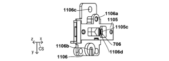
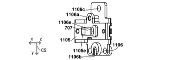
- Figs. 7B and 7D are perspective views focusing on the light-emitting element 202, the light-receiving element 204, the light-reflecting portion 207, the light-shielding wall 704, and the light-shielding wall 705.
- the light-shielding wall 704 in which an opening 706 is formed functions as the aperture section 209 on the incident light 211 side
- the light-shielding wall 705 in which an opening 707 is formed functions as the aperture section 210 on the reflected light 212 side.
- the portion of the light-shielding wall 704 above the upper edge of the opening 706 corresponds to the first aperture section. Therefore, part of the light emitted by the light-emitting element 202 is blocked by the light-shielding wall 704 and does not reach the light reflecting section 207.
- both openings 706 and 707 are rectangular.
- the side that is parallel to the diaphragm 206 and closer to the diaphragm 206 is referred to as the lower side
- the side that is parallel to the diaphragm 206 and farther from the diaphragm 206 is referred to as the upper side
- the side to the left as viewed from the light-emitting element 202 is referred to as the left side
- the side to the right as viewed from the light-emitting element 202 is referred to as the right side.
- incident light 211 and reflected light 212 represent light beams that reach the light receiving element 204.
- some of the light emitted from the light emitting element 202, light 710 passes through the opening 706 in the light shielding wall 704 and is reflected by the light reflecting portion 207 to become light 711, but is blocked by a portion of the light shielding wall 705 that is above the reflected light 212 and does not reach the light receiving element 204.
- the same is true in Figure 7D.
- the portion of the light reflecting portion 207 where the incident light 211 reaches when the diaphragm 206 is not pressed by the biological surface 300 is referred to as the effective range 700.
- the effective range 700 is the portion of the light reflecting portion 207 that reflects the light that reaches the light receiving element 204. When the diaphragm 206 is not pressed, the effective range 700 is equal to the range where the light from the light emitting element 202 reaches.
- the effective range 700 is a rectangular area.
- the outer periphery of the effective range 700 is referred to as the boundary line of the effective range 700.
- the boundary line of the effective range 700 is located between the effective range 700 and the area other than the effective range 700. In the following description, part of the boundary line is also referred to as the boundary line.
- the line segment that includes the farthest position in the x-axis direction from the light-emitting element 202 is represented as the far boundary 700a.
- the portion of the incident light 211 that reaches the far boundary 700a is represented as the far incident light 211a.
- the far incident light 211a means that it includes the portion where the optical path from the light-emitting element 202 to the light reflecting portion 207 is the longest.
- the angle of incidence of the incident light 211 to the light reflecting portion 207 is maximum value 703a at a position on the far boundary 700a.
- the line segment that includes the position closest to the light-emitting element 202 in the x-axis direction is represented as the near boundary 700b.
- the portion of the incident light 211 that reaches the near boundary 700b is represented as the near incident light 211b.
- the near incident light 211b means that it includes the portion where the optical path from the light-emitting element 202 to the light reflecting portion 207 is the shortest.
- the angle of incidence of the incident light 211 to the light reflecting portion 207 becomes a minimum value 703b at a position on the near boundary 700b.
- the light that is not included between the far incident light 211a and the near incident light 211b is attenuated by being reflected multiple times by the light-shielding wall 704.
- the two line segments other than the far boundary 700a and the near boundary 700b are referred to as lateral boundary lines 700c and 700d.
- the lateral boundary line 700c is located on the right side of the effective range 700 as seen from the light-emitting element 202
- the lateral boundary line 700d is located on the left side of the effective range 700 as seen from the light-emitting element 202.
- the area of the light receiving element 204 formed by the reflected light 212 specularly reflected by the light reflecting portion 207 is represented as the light irradiation area 701.
- the light irradiation area 701 is a portion of the light receiving element 204 where the light emitted from the light emitting element 202 and specularly reflected by the light reflecting portion 207 reaches. In addition to the light specularly reflected by the light reflecting portion 207, scattered light may also reach the light receiving element 204.
- the light irradiation area 701 is defined as the area formed by the specularly reflected light.
- the amount of light that reaches the light receiving element 204 is proportional to the area of the light irradiation area 701.
- the light irradiation area 701 is a rectangular area.
- the outer periphery of the light irradiation area 701 is represented as the boundary line of the light irradiation area 701.
- the boundary line of the light irradiation area 701 is located between the light irradiation area 701 and an area other than the light irradiation area 701.
- the line segment formed by the light narrowed by the aperture section 209 and specularly reflected by the light reflection section 207 is represented as the lower boundary 701a.
- the line segment on the opposite side of the lower boundary 701a is represented as the upper boundary 701b.
- the lower boundary 701a is an example of a boundary formed by the light narrowed by the aperture section 209 and specularly reflected by the light reflection section 207.
- the lower boundary 701a is a boundary that moves in response to the displacement of the contact surface 206a, as described below.
- the area of the light irradiation area 709 changes due to the movement of the lower boundary 701a, and the output of the light receiving element 204 changes.
- the upper boundary 701b is an example of a boundary that does not move in response to the displacement of the contact surface 206a and does not change in length even if the contact surface 206a is displaced.
- the two line segments other than the lower boundary 701a and the upper boundary 701b are represented as side boundary lines 701c and 701d.
- the side boundary line 701c is located on the right side of the light-irradiated region 701 as seen from the light-emitting element 202, and the side boundary line 701d is located on the left side of the light-irradiated region 701 as seen from the light-emitting element 202.
- the side boundary lines 701c and 701d are examples of boundary lines that do not move in response to the displacement of the contact surface 206a, as described below, but whose length changes when the contact surface 206a is displaced.
- the light passing through the opening 706 along the upper edge of the opening 706 is specularly reflected by the light reflecting portion 207, and then reaches the lower boundary line 701a of the light irradiation area 701 of the light receiving element 204 without being blocked by the light-shielding wall 705. Therefore, the upper edge of the opening 706 defines the lower boundary line 701a of the light irradiation area 701.
- the light passing through the opening 706 along the lower edge of the opening 706 is specularly reflected by the light reflecting portion 207, and then is blocked by the light-shielding wall 705, and does not reach the light receiving element 204. Therefore, the lower edge of the opening 706 does not define the light irradiation area 701.
- the near incident light 211b is not narrowed by the aperture portion 209.
- the light passing through the opening 706 along the lower edge of the opening 706 may be configured to be specularly reflected by the light reflecting portion 207, and then reaches the light receiving element 204 without being blocked by the light-shielding wall 705.
- the bottom side of the opening 706 defines the light irradiation area 701.
- the displacement signal in FIG. 5 remains constant when the displacement of the diaphragm 206 ranges from zero to a predetermined value. Thereafter, when the bottom side of the opening 706 no longer defines the light irradiation area 701, the displacement signal begins to decrease monotonically.
- the light that passes through the opening 706, is specularly reflected by the light reflecting portion 207, and then passes through the opening 707 along the upper edge of the opening 707 reaches the upper boundary 701b of the light irradiation area 701 of the light receiving element 204. Therefore, the upper edge of the opening 707 defines the upper boundary 701b of the light irradiation area 701.
- the upper edge of the opening 707 is an example of an aperture section that narrows down the light specularly reflected by the light reflecting portion 207.
- the lower edge of the opening 707 does not define the light irradiation area 701.
- the lateral boundary lines 701c and 701d of the light irradiation area 701 are defined by the right and left sides of the opening 707.
- the lateral boundary lines 701c and 701d of the light irradiation area 701 may be defined by the right and left sides of the opening 706.
- the reflected light of the distant incident light 211a is represented as the lower end reflected light 212a.
- the lower end reflected light 212a is the light located at the lowest position in the z-axis direction among the reflected light 212 (i.e., the part closest to the diaphragm 206).
- the lower end reflected light 212a reaches the lower boundary line 701a of the light irradiation area 701.
- the lower boundary line 701a is formed by light narrowed by the aperture section 209 and specularly reflected by the light reflection section 207.
- the lower end reflected light 212a is away from each side of the opening 705. In other words, the lower end reflected light 212a is not narrowed by the aperture section 210.
- the lower boundary line 701a includes the position of the light irradiation area 701 closest to the diaphragm 206 in the normal direction (i.e., the z-axis direction) of the diaphragm 206 when not pressed by the biological surface 300.
- the lower boundary line 701a includes the position in the light irradiation area 701 where the light reaches with the maximum reflection angle at the light reflecting portion 207. This maximum reflection angle is equal to the maximum incidence angle 703a.
- the lower boundary line 701a includes the position farthest from the light emitting element 202 in a plan view of the diaphragm 206 in an unpressed state.
- the reflected light of the near incident light 211b is represented as the upper end reflected light 212b.
- the upper end reflected light 212b is the light located at the top of the reflected light 212 in the z-axis direction (i.e., the part farthest from the diaphragm 206).
- the upper end reflected light 212b reaches the upper boundary line 701b of the light irradiation area 701.
- the upper boundary line 701b includes the position in the light irradiation area 701 that is farthest from the diaphragm 206 in the normal direction (i.e., the z-axis direction) of the diaphragm 206 in the unpressed state.
- the upper boundary line 701b includes the position in the light irradiation area 701 where the light reaches with the smallest reflection angle at the light reflecting portion 207. This minimum reflection angle is equal to the minimum incident angle 703b. Furthermore, in the configurations of Figures 7A and 7B, the upper boundary 701b includes the position closest to the light emitting element 202 in a plan view of the diaphragm 206 in an unpressurized state.
- the positions of the effective range 700, the far boundary 700a, the near boundary 700b, the light irradiation area 701, the lower boundary 701a, and the upper boundary 701b change.
- the part of the reflected light 212 that is farthest from the light-emitting element 202 in the x-axis direction is called the lower end reflected light 212a.
- the lower end reflected light 212a reaches the lower boundary 701a of the light irradiation area 701.
- the lower boundary 701a is determined by the upper side of the opening 706 of the aperture section 209 on the light-emitting element 202 side.
- the lower boundary 701a moves in response to the displacement of the contact surface 206a due to the elastic deformation of the diaphragm 206, which changes the area of the light irradiation area 701 and the output of the light-receiving element 204, as described below.
- the displacement of the lower boundary 701a corresponds to the displacement d3 of the reflected light 212 described in Figures 4A to 4F. That is, the lower boundary 701a is displaced by a displacement magnification G relative to the displacement d2 of the diaphragm 206.
- the position where the farthest part of the reflected light 212 from the light emitting element 202 (within three-dimensional space, not in the x-axis direction) reaches the light receiving element 204 is also displaced by the displacement magnification G.
- the upper boundary 701b is determined by the portion of the light-shielding wall 705 that is above the reflected light 212, and is a boundary that does not move in response to the displacement of the contact surface 206a and does not change in length even if the contact surface 206a is displaced.
- the portion of the light-shielding wall 704 that is below the incident light 211 does not need to block the light emitted from the light-emitting element 202.
- the portion of the light-shielding wall 704 that is below the incident light 211 does not need to be provided.
- the lower boundary 701a is determined by the portion of the light-shielding wall 704 that is above the incident light 211.
- the portion of the light-shielding wall 705 that is below the reflected light 212 does not need to block the light that is specularly reflected by the light reflecting portion 207.
- the portion of the light-shielding wall 705 that is below the reflected light 212 does not need to be provided.
- Fig. 7E shows a plan view of the light receiving surface of the light receiving element 204.
- the left side of Fig. 7E shows the position of the light irradiation area 701 when the diaphragm 206 is not pressed.
- the right side of Fig. 7E shows the position of the light irradiation area 701 when the diaphragm 206 is pressed by the biological surface 300.
- Coordinate system CS' is a two-dimensional Cartesian coordinate system with mutually orthogonal x' and y' axes.
- the y' axis coincides with the y axis of coordinate system CS.
- the x' axis is parallel to the xz plane of coordinate system CS.
- the positive direction of the x' axis is referred to as the upper side, and the negative direction of the x' axis is referred to as the lower side.
- the surface of the light receiving element 204 that faces the internal space 213 is the light receiving surface.
- the light receiving element 204 detects the amount of light that reaches the light receiving surface.
- the light receiving element 204 is a single light receiving element. Instead of a single light receiving element, a line sensor or an area sensor may be used.
- the light receiving surface may have a rectangular shape. Of the four sides of the light receiving surface, the side that is parallel to the diaphragm 206 and closer to the diaphragm 206 is represented as side 204a.
- the area of the light irradiation region 701 is determined by the lower boundary line 701a, the upper boundary line 701b, and the side boundary lines 701c and 701d.
- the lower boundary line 701a of the light irradiation region 701 changes in the x'-axis direction in response to the displacement of the contact surface 206a.
- the upper boundary line 701b and the side boundary lines 701c and 701d do not substantially move in response to the displacement of the contact surface 206a. Therefore, the area of the light irradiation region 701 changes in response to the movement of the lower boundary line 701a.
- the length of the upper boundary line 701b does not change even if the contact surface 206a is displaced.
- the lengths of the side boundary lines 701c and 701d change when the contact surface 206a is displaced.
- the signal output from the light-receiving element 204 also changes. Specifically, the greater the displacement of the contact surface 206a of the diaphragm 206 from the flat state, the shorter the distance between the lower boundary 701a and the upper boundary 701b (i.e., the length of the lateral boundary lines 701c and 701d), and the smaller the area of the light-irradiated region 701. Therefore, the greater the displacement of the diaphragm 206 from the flat state, the less light the light-receiving element 204 receives. Accordingly, the signal output from the light-receiving element 204 also becomes smaller. As shown in FIG. 7E, the amount of movement of the lower boundary line 701a accompanying the movement of the light-reflecting portion 207 is greater than the amount of movement of the upper boundary line 701b accompanying the movement of the light-reflecting portion 207.
- the change in the light irradiation area 701 in the x'-axis direction is greater than the change in the light irradiation area 701 in the y'-axis direction. Therefore, in order to increase the dynamic range of the light receiving element 204, it is preferable that the width of the light receiving element 204 in the x'-axis direction be greater than the width of the light receiving element 204 in the y'-axis direction. More specifically, it is preferable that the width of the light receiving element 204 in the x'-axis direction be three or more times the width of the light receiving element 204 in the y'-axis direction.
- FIG. 8A and 8B A first modified example of the chestpiece 110 will be described with reference to Figures 8A and 8B. In Figures 8A and 8B, differences from Figures 7B and 7D will be mainly described.
- the light-shielding wall 705 is omitted. Therefore, the chestpiece 110 does not have the aperture section 210.
- the upper boundary line 701b of the light irradiation area 701 is defined by a line segment that forms the edge of the light receiving area of the light receiving element 204 (specifically, the upper edge of the light receiving area of the light receiving element 204).
- the lateral boundaries 701c and 701d of the light irradiation region 701 are defined by the line segments that form the edges of the light receiving region of the light receiving element 204 (specifically, the right and left sides of the light receiving region of the light receiving element 204).
- the lateral boundaries 701c and 701d of the light irradiation region 701 may be defined by the right and left sides of the opening 706.
- the light that passes through the opening 706, is specularly reflected by the light reflecting portion 207, and then passes through the opening 707 along the lower edge of the opening 707 reaches the lower boundary line 701a of the light irradiation area 701 of the light receiving element 204. Therefore, the lower edge of the opening 707 defines the lower boundary line 701a of the light irradiation area 701. On the other hand, since it is blocked by the light shielding wall 704, the light does not pass through the portion along the lower edge of the opening 707. Therefore, the upper edge of the opening 707 does not define the light irradiation area 701.
- the positions of the effective range 700, the far boundary 700a, the near boundary 700b, the light irradiation area 701, the lower boundary 701a, and the upper boundary 701b change.
- the upper boundary 701b is defined by the lower side of the opening 706 of the aperture section 209 on the light-emitting element 202 side.
- the upper boundary 701b moves in response to the displacement of the contact surface 206a.
- the lower boundary 701a and the lateral boundary lines 701c and 701d do not substantially move in response to the displacement of the contact surface 206a.
- the upper boundary 701b is displaced by a displacement magnification G with respect to the displacement amount d2 of the diaphragm 206.
- the displacement magnification G has the same value as that in Table 1 above.
- the displacement signal represents a voltage output from the optical receiver circuit board 205.
- a graph 800 in Fig. 8E represents the relationship between the displacement amount of the biological surface 300 and the displacement signal.
- the horizontal axis of the graph 800 represents the displacement amount of the biological surface 300, and represents the displacement signal generated by the optical receiver circuit board 205.
- the displacement signal When the displacement of the biological surface 300 is zero, the displacement signal has a value according to the area of the light irradiation region 701 shown in FIG. 8C.
- the displacement of the contact surface 206a increases, the upper end reflected light 212b moves in a direction away from the diaphragm 206, and the area of the light irradiation region 701 increases monotonically and linearly.
- the amount of light that reaches the light receiving element 204 out of the light emitted by the light emitting element increases monotonically and linearly.
- the displacement signal output from the light receiving element 204 also increases monotonically and linearly. Thereafter, when the upper end reflected light 212b reaches the light shielding wall 705, the displacement signal becomes constant.
- the light shielding wall 705 is omitted. Therefore, the chest piece 110 does not have the diaphragm portion 210.
- the light passing through the opening 706 along the lower side of the opening 706 is specularly reflected by the light reflecting portion 207, and then reaches the upper side of the light irradiation area 701 of the light receiving element 204. Therefore, the lower side of the opening 706 defines the upper side of the light irradiation area 701.
- the light passing through the opening 706 along the upper side of the opening 706 is specularly reflected by the light reflecting portion 207, and then reaches the outside of the light receiving element 204. Therefore, the upper side of the opening 706 does not define the light irradiation area 701.
- the lower side of the light irradiation area 701 is defined by the lower side of the light receiving element 204.
- the left and right sides of the light irradiation area 701 are defined by the left and right sides of the light receiving element 204.
- the left and right sides of the light irradiation area 701 may be defined by the left and right sides of the opening 706 .
- the chest piece 110 further has a lens 900 between the light emitting element 202 and the light reflecting portion 207.
- the lens 900 converts the diffuse light emitted by the light emitting element 202 into parallel light. Because this parallel light reaches the light reflecting portion 207, the chest piece 110 can eliminate the aperture portion 209 on the side of the incident light 211.
- the change in the light irradiation area 701 is the same as that described in Figures 7A and 7C. Therefore, the range of light that reaches the light receiving element 204 (i.e., the light irradiation area 701) changes in the x'-axis direction as the light reflecting portion 207 moves.
- Fig. 9C is a diagram summarizing whether the upper and lower sides of the openings 706 and 707 define the light irradiation area 701 in each of the first embodiment and the first to fourth modified examples.
- the "cross-sectional configuration" in Fig. 9C shows the cross-sectional configuration of the light emitting element 202, the light receiving element 204, the light reflecting portion 207, the openings 706 and 707 in each configuration in a simplified manner.
- the "change in displacement signal" in Fig. 9C shows whether the signal decreases monotonically as in the graph 500 in Fig. 5 or increases monotonically as in the graph 800 in Fig. 8E.
- the normal to the light receiving surface of the light receiving element 204 is inclined with respect to the z-axis direction (i.e., the normal direction of the diaphragm 206).
- the normal to the light receiving surface of the light receiving element 204 may coincide with the z-axis direction.
- the light receiving surface is parallel to the diaphragm 206.
- the chestpiece 110 includes only one light-emitting element 202.
- the chestpiece 110 may include multiple light-emitting elements 202.
- the light emitted by the multiple light-emitting elements 202 may be reflected by the light reflecting portion 207 and reach the light-receiving element 204.
- the light-receiving element 204 may detect the displacement of the diaphragm 206 based on the total amount of light.
- the chestpiece 110 may include multiple light-receiving elements 204.
- Each of the multiple light-receiving elements 204 may receive light emitted from a separate light-emitting element 202 and reflected by the light reflecting portion 207.
- the displacement of the diaphragm 206 may be detected based on the total amount of light received by the multiple light-receiving elements 204.
- the electronic auscultation device 100 generates a displacement signal (i.e., a signal representing the displacement of the diaphragm 206) based on the amount of light emitted from the light-emitting element 202, reflected by the light reflecting portion 207, and received by the light-receiving element 204.
- the electronic auscultation device 100 may detect the displacement signal based on the light received by the light-receiving element 204 in another manner.
- the light-emitting element 202 may emit laser light toward the light reflecting portion 207. The laser light reflected by the light reflecting portion 207 reaches the light-receiving element 204.
- the position at which the laser light reaches the light-receiving element 204 differs depending on the displacement of the diaphragm 206. Therefore, the electronic auscultation device 100 may detect the displacement signal based on the position of the light received by the light-receiving element 204.
- the chestpiece 110 may not include the aperture portions 209 and 210.
- the light-receiving element 204 may be a two-dimensional area sensor or a one-dimensional line sensor.
- Second Embodiment A configuration example of an electronic auscultation device 1000 according to the second embodiment will be described with reference to Figures 10 to 13K. Differences from the electronic auscultation device 100 according to the first embodiment will be mainly described below. The appearance of the electronic auscultation device 1000 is similar to that of the electronic auscultation device 100 described with reference to Figures 1A and 1B. The modified examples described in the first embodiment may also be applied to the second embodiment.
- the hardware configuration of the electronic auscultation device 1000 will be described with reference to Figure 10.
- the difference between Figure 10 and Figure 6 is that the electronic auscultation device 1000 has a chest piece 1010 and a sound output unit 1020 instead of the chest piece 110 and sound output unit 610 of the electronic auscultation device 100.
- the electronic auscultation device 1000 is composed of the chest piece 1010 and the sound output unit 1020 included in the grip unit 120 ( Figures 1A and 1B).
- the chest piece 1010 has a displacement detection unit 1011 and a vibration detection unit 1012.
- the displacement detection unit 1011 like the electronic auscultation device 100, is composed of main components including a light-emitting element 202, a light-receiving element 204, and a light reflecting unit 207.
- the displacement detection unit 1011 generates a displacement signal (i.e., a signal representing the displacement of the diaphragm 206) based on the amount of light emitted from the light emitting element 202, reflected by the light reflecting unit 207, and received by the light receiving element 204.
- the displacement detection unit 1011 may detect the displacement signal based on the light received by the light receiving element 204 in another manner.
- the light emitting element 202 may emit a laser beam toward the light reflecting unit 207.
- the laser beam reflected by the light reflecting unit 207 reaches the light receiving element 204.
- the position at which the laser beam reaches the light receiving element 204 differs depending on the displacement of the diaphragm 206.
- the displacement detection unit 1011 may detect the displacement signal based on the position of the light received by the light receiving element 204.
- the chest piece 1010 may not include the aperture units 209 and 210.
- the light-receiving element 204 may be a two-dimensional area sensor or a one-dimensional array sensor.
- the vibration detection unit 1012 detects air vibrations caused by the displacement of the diaphragm 206.
- the vibration detection unit 1012 is also called a sound detection unit because it detects the sound represented by the air vibrations.
- the vibration detection unit 1012 is configured, for example, with a capacitor-type microphone 1101 ( Figure 11C).
- the vibration detection unit 1012 generates a sound signal representing the detected air vibrations.
- the sound signal may be an electrical signal (for example, a voltage signal).
- the displacement signal generated by the displacement detection unit 1011 and the sound signal generated by the vibration detection unit 1012 are each supplied to the sound output unit 1020.
- the sound output unit 1020 performs signal processing on the displacement signal and sound signal supplied from the chest piece 1010 in the same manner as the sound output unit 610 of the electronic auscultation device 100, and transmits the signals to the outside of the sound output unit 1020 (e.g., the sound output device 620 or the computer 630).
- the frequency bands to which the displacement detection unit 1011 and the vibration detection unit 1012 have high sensitivity may differ.
- the displacement detection unit 1011 can detect vibrations (e.g., heartbeat sounds) in a low frequency band (e.g., 100 Hz or less) with better sensitivity than the vibration detection unit 1012.
- the vibration detection unit 1012 can detect vibrations (e.g., breathing sounds) in a high frequency band (e.g., 100 Hz or more) with better accuracy than the displacement detection unit 1011. Therefore, since the sound output unit 1020 can output both the displacement signal and the sound signal, the electronic auscultation device 1000 can detect vibrations in a wide frequency band with better accuracy.
- a high frequency band e.g. 100 Hz or more
- the sound output unit 1020 includes an output selection unit 1021 in addition to each of the components included in the sound output unit 610 of the electronic auscultation device 100.
- the output selection unit 1021 selects whether the displacement signal or the sound signal supplied from the chestpiece 1010 is to be output to the outside. For example, when the destination is the sound output device 620, the output selection unit 1021 outputs only the selected one of the displacement signal or the sound signal. When the destination is the computer 630, the output selection unit 1021 may output only the selected one of the displacement signal or the sound signal, or may output both the displacement signal and the sound signal. In this way, the sound output unit 1020 can selectively output the displacement signal or the sound signal to the outside.
- the operation unit 123 of the electronic auscultation device 1000 obtains a designation from the user as to whether to output a displacement signal or a sound signal.
- a mode switching button 123c is provided on the operation unit 123 in FIG. 1A.
- the output selection unit 1021 switches the signal to be output to the external device between the displacement signal and the sound signal.
- the mode switching button 123c provided on the operation unit 123 to select the heartbeat mode, which is one of the auscultation modes.
- auscultating respiratory sounds the user operates the mode switching button 123c provided on the operation unit 123 to select the respiratory sound mode, which is one of the auscultation modes.
- the output selection unit 1021 selects whether to output a displacement signal indicating the displacement detected by the displacement detection unit 1011 or a sound signal detected by the vibration detection unit 1012.
- the operation unit 123 is also provided with volume adjustment buttons 123a and 123b for adjusting the gain of the displacement signal output by the electronic auscultation device 100.
- the volume adjustment buttons 123a and 123b are used to adjust the volume of the sound output by the electronic auscultation device 100.
- the display unit 122 of the electronic auscultation device 1000 is provided with an LED as an indicator that indicates whether the signal currently selected as the output target is a displacement signal or a sound signal. Depending on the lighting state of this LED, the user can visually confirm whether the operating mode is the heartbeat sound mode or the breath sound mode.
- the heartbeat sound mode and the breath sound mode are each an example of an auscultation mode.
- the output selection unit 1021 controls the wireless communication unit 614 and the wired communication unit 617 to determine the type of signal to be output externally. Alternatively, the output selection unit 1021 may determine whether the displacement signal or the sound signal is to be supplied to the A/D converter 611 and the amplifier 615. Furthermore, in the example of FIG. 10, the sound output unit 1020 includes the output selection unit 1021, but instead, the chest piece 1010 may include the output selection unit 1021. The output selection unit 1021 in the chest piece 1010 may determine the type of signal to be supplied to the sound output unit 1020.
- FIG. 11A is a plan view of the chest piece 1010.
- Fig. 11B is an enlarged cross-sectional view of the chest piece 1010 taken along line A-A in Fig. 11A.
- Fig. 11C is an enlarged cross-sectional view of the chest piece 1010 taken along line B-B in Fig. 11A.
- Fig. 12A is a perspective view of the chest piece 1010 disassembled and with each component separated.
- Fig. 12B is a perspective view showing the shape of the sealed space 1100.
- Figs. 11A is a plan view of the chest piece 1010.
- Fig. 11B is an enlarged cross-sectional view of the chest piece 1010 taken along line A-A in Fig. 11A.
- Fig. 11C is an enlarged cross-sectional view of the chest piece 1010 taken along line B-B in Fig. 11A.
- Fig. 12A is a perspective view of the chest piece 1010 disassembled and with each component separated.
- FIGS. 13A to 13C are perspective views of the lower holding member 1105 as viewed from various angles.
- Figs. 13D to 13F are perspective views of the upper holding member 1106 as viewed from various angles.
- Fig. 13G is a perspective view of the base holding member 1104 as viewed from a certain angle.
- Figs. 13H to 13K are perspective views of the lower holding member 1105 and the upper holding member 1106 as viewed from various angles in a combined state.
- Fig. 13H is a perspective view seen from an angle where the light emitting element 202 is seen through the opening 706, and
- Fig. 13I is a perspective view seen from an angle where the light receiving element 204 is seen through the opening 707.
- Fig. 13H is a perspective view seen from an angle where the light emitting element 202 is seen through the opening 706
- Fig. 13I is a perspective view seen from an angle where the light receiving element 204 is seen through the opening 707.
- Fig. 13H is a
- FIG. 11A the light emitting element 202, the light receiving element 204, the light reflecting portion 207, and the microphone 1101 are depicted as visible for ease of understanding, but these components are covered and hidden by the housing 208.
- FIGs. 11B and 11C for ease of understanding, the same hatching is applied to cross sections of the same components, and different hatching is applied to cross sections of different components.
- a mechanism for attaching the chest piece 1010 to the grip portion 120 is omitted.
- the chest piece 1010 further includes a microphone 1101, a sealing member 1102, and a relay circuit board 1103 in addition to the components included in the chest piece 110 of the electronic stethoscope device 100.
- the microphone 1101 constitutes the vibration detection unit 1012.
- the relay circuit board 1103 is connected to the light-emitting circuit board 203 by a lead wire (not shown). Through this lead wire, the relay circuit board 1103 transmits a control signal to the light-emitting circuit board 203 to instruct it to emit light, and supplies power.
- the relay circuit board 1103 is also connected to the light-receiving circuit board 205 by a lead wire (not shown). Through this lead wire, the relay circuit board 1103 receives a displacement signal from the light-receiving circuit board 205, and supplies power to the light-receiving circuit board 205.
- the relay circuit board 1103 is also connected to the microphone 1101 by a lead wire (not shown).
- the relay circuit board 1103 receives a sound signal from the microphone 1101, and supplies power to the microphone 1101.
- the relay circuit board 1103 is also connected to the circuit board in the gripping portion 120 by a cable (not shown).
- the relay circuit board 1103 transmits a displacement signal and a sound signal to the circuit board in the gripping portion 120 via this cable, receives a control signal for controlling the operation of the chest piece 110 from the circuit board in the gripping portion 120, and receives a supply of power.
- a hole 208a is formed in the housing 208 for passing a cable connecting the relay circuit board 1103 and the circuit board in the gripping portion 120.
- a "hole” means a through hole that penetrates the member in which the hole is formed.
- a "recess" means that the recess does not penetrate the member in which the recess is formed.
- the holding member 201 is composed of a base holding member 1104, a lower holding member 1105, and an upper holding member 1106.
- a diaphragm 206 is attached to the base holding member 1104 so as to cover the lower surface of the base holding member 1104.
- the outer periphery of the diaphragm 206 is folded back to form a recess, and the diaphragm 206 is attached to the base holding member 1104 by fitting a protrusion on the outer periphery of the base holding member 1104 into this recess of the diaphragm 206.
- the diaphragm 206 may be attached to the base holding member 1104 by, for example, gluing.
- the diaphragm 206 can be displaced relative to the lower surface of the base holding member 1104.
- the lower surface of the base holding member 1104 has a recess near its center so as not to hinder the displacement of the diaphragm 206.
- the housing 208 is attached to the base holding member 1104 so as to cover the upper surface of the base holding member 1104.
- the base holding member 1104 has a screw thread or a thread groove on its outer periphery, and the housing 208 has a screw groove or a screw thread on the inside of its lower end. These screw threads and screw grooves fit together to attach the housing 208 to the base holding member 1104.
- the housing 208 may be attached to the base holding member 1104 by, for example, gluing.
- the housing 208 covers the light-emitting element 202, the light-emitting circuit board 203, the light-receiving element 204, the light-receiving circuit board 205, and the microphone 1101 attached to the holding member 201, and has the function of blocking sound so that ambient sound is not detected as noise.
- Two further holding members (lower holding member 1105 and upper holding member 1106) are arranged on the base holding member 1104.
- the lower holding member 1105 is located on the opposite side of the base holding member 1104 from the diaphragm 206 in the z direction.
- a convex portion 1104d formed on the upper surface of the base holding member 1104 fits into a concave portion 1105d formed on the underside of the lower holding member 1105, and the lower holding member 1105 is aligned with the base holding member 1104.
- the upper holding member 1106 is disposed above the base holding member 1104 and the lower holding member 1105 in the z-direction.
- the upper holding member 1106 is located on the opposite side of the base holding member 1104 from the diaphragm 206.
- the lower holding member 1105 is located between the upper holding member 1106 and the base holding member 1104.
- the upper holding member 1106 is aligned with the lower holding member 1105 by fitting a convex portion 1106a formed on the underside of the upper holding member 1106 into a hole 1105b formed in the lower holding member 1105.
- the relay circuit board 1103 is disposed on the upper holding member 1106.
- a screw (not shown) passing through a hole 1103a formed in the relay circuit board 1103 and a hole 1106c formed in the upper holding member 1106 is engaged with a screw hole 1104c formed in the base holding member 1104.
- three screw holes are formed in the base holding member 1104, and a screw passing through the relay circuit board 1103 and the upper holding member 1106 is engaged with each of these.
- the method of fixing the lower holding member 1105, the upper holding member 1106, and the relay circuit board 1103 to the base holding member 1104 is not limited to this, and they may be fixed, for example, by adhesive.
- the light emitting element 202 is inserted into a hole formed by the engagement of the upper holding member 1106 and the lower holding member 1105.
- the light receiving element 204 is arranged so as to cover the hole formed by the engagement of the upper holding member 1106 and the lower holding member 1105.
- the microphone 1101 is arranged in a hole 1104b formed in the base holding member 1104.
- a sealing member 1102 is arranged between the microphone 1101 and the base holding member 1104 to seal the gap between these members, improving the airtightness in the sealed space described below.
- a convex portion 1106b formed on the lower surface of the upper holding member 1106 is arranged above the hole 1104b of the base holding member 1104.
- the convex portion 1106b may press the microphone 1101 downward (i.e., toward the diaphragm 206).
- the microphone 1101 is positioned so as not to overlap the optical path of the light (i.e., incident light 211 and reflected light 212) traveling from the light-emitting element 202 to the light-receiving element 204 via the light reflecting portion 207 in a plan view of the diaphragm 206 (i.e., when viewed from the positive z-axis direction).
- a T-shaped hole 1104a is formed near the center of the base holding member 1104.
- a hole 1105a is formed near the center of the lower holding member 1105.
- the incident light 211 passes through the holes 1104a and 1105a from the light emitting element 202 to the light reflecting portion 207.
- the reflected light 212 passes through the holes 1104a and 1105a from the light reflecting portion 207 to the light receiving element 204. In this way, no other components are arranged on the optical path of the light (i.e., the incident light 211 and the reflected light 212) traveling from the light emitting element 202 to the light receiving element 204 via the light reflecting portion 207.
- the base holding member 1104 covers the area of the inner surface 206b of the diaphragm 206 other than the area where the light reflecting portion 207 is fixed.
- the upper holding member 1106 has a light-shielding wall 1106d that extends in a direction intersecting the diaphragm 206 (the yz plane in the example of FIG. 11B).
- the upper part of the light-shielding wall 1106d on the upper side of the opening 706 corresponds to the first diaphragm portion.
- the lower holding member 1105 has a light-shielding wall 1105c that extends in a direction along the diaphragm 206 (the xy plane in the example of FIG. 11B).
- the light-shielding wall 1106d and the light-shielding wall 1105c form the diaphragm portion 209 on the incident light 211 side.
- the light-shielding wall 1106d and the light-shielding wall 1105c each block a portion of the light emitted by the light-emitting element 202.
- a portion of the light-shielding wall 1105c may enter the hole 1104a of the base holding member 1104. This allows the diaphragm portion 209 to be closer to the light reflecting portion 207, thereby reducing the spread of the incident light 211.
- the upper holding member 1106 has a light-shielding wall 1106e that protrudes downward in the z direction at a position where the reflected light by the light reflecting portion 207 reaches.
- the lower holding member 1105 has a light-shielding wall 1105e at a position where the reflected light by the light reflecting portion 207 reaches.
- the light-shielding wall 1106e and the light-shielding wall 1105e form the aperture section 210 on the reflected light 212 side. That is, the light-shielding wall 1106e and the light-shielding wall 1105e each block a part of the light specularly reflected by the light reflecting portion 207.
- the light-shielding wall 1106d provided on the upper holding member 1106 and the light-shielding wall 1105c provided on the lower holding member 1105 serve as an aperture section that blocks the incident light 211 and the reflected light 212, and also serve to narrow the sealed space. In other words, the light-shielding walls 1105c and 1106d narrow the volume of the enclosed space (internal space), increasing the volume change rate described below, and as a result, the sensitivity of the microphone 1101 can be improved.
- the sealed space 1100 is defined by the diaphragm 206, the light reflecting portion 207, the base holding member 1104, the lower holding member 1105, the upper holding member 1106, the light emitting element 202, the light receiving element 204, and the microphone 1101. Therefore, the space facing the inner surface 206b of the diaphragm 206 is a sealed space.
- a sealed space is a space that is sealed against a specific substance. In other words, a sealed space is a space in which the inflow of a specific substance from an external space or external environment and the outflow of a specific substance to an external space or external environment are suppressed. Therefore, there are no passages such as gaps or holes connecting the sealed space 1100 to the outside.
- the substance to be sealed may vary depending on the usage environment of the electronic auscultation device 1000.
- the substance to be sealed may be a gas (e.g., air)
- the substance to be sealed may be a liquid (e.g., water).
- the sealed space 1100 is the space facing the inner surface 206b of the diaphragm 206 and surrounded by the hatched components.
- the portion of the lower holding member 1105 that defines the sealed space 1100 includes the above-mentioned light-shielding wall 1105c.
- the portion of the upper holding member 1106 that defines the sealed space 1100 includes the above-mentioned light-shielding wall 1106d.
- the sealed space 1100 is further defined by the light-receiving circuit board 205.
- the sealed space 1100 is further defined by the seal member 1102.
- the sealed space 1100 does not have to be sealed when the electronic auscultation device 100 is not in use.
- the diaphragm 206 and the base holding member 1104 may not be in close contact when the electronic auscultation device 100 is not in use, but may be in close contact when the diaphragm 206 is pressed against the surface of the living body, thereby forming the sealed space 1100.
- the sound detection surface 1101a of the microphone 1101 faces the sealed space 1100. This allows the microphone 1101 to detect air vibrations in the internal space 212 caused by the displacement of the contact surface 206a of the diaphragm 206. The microphone 1101 generates a sound signal that represents these air vibrations.
- the portion of diaphragm 206 that comes into contact with the surface of the living body is composed of a sheet-like flexible material.
- Diaphragm 206 separates sealed space 1100 from the outside of chest piece 1010.
- Diaphragm 206 has the property of deforming in response to an external force applied to diaphragm 206 (e.g., a force from the surface of the living body) and returning to its original shape when the external force is removed. Due to this property, the air pressure in sealed space 1100 changes in response to vibrations transmitted from the surface of the living body to diaphragm 206.
- Sound detection surface 1101a of microphone 1101 vibrates in response to the air pressure in sealed space 1100, and microphone 1101 converts the vibrations of sound detection surface 1101a into an electrical signal.
- the inner surface 206b of the diaphragm 206 and the sound detection surface 1101a of the microphone 1101 face the sealed space 1100, allowing the microphone 1101 to efficiently detect sound signals corresponding to the displacement of the surface of the living body.
- the sealed space 1100 is configured so that the volume of the sealed space 1100 is smaller than the volume of the internal space of the chest piece 110. That is, in this embodiment, the sealed space 1110 does not face the housing 208, and is separated from the space facing the inner surface of the housing 208. However, it goes without saying that the space facing the inner surface of the housing 208 may also be the sealed space.
- the internal space other than the sealed space 1110 of the chest piece 110 is not sealed, but may be sealed if, for example, the electronic stethoscope device 1000 is required to be waterproof or dustproof.
- the housing 208 is formed with a hole 208a for passing a cable. The gap between this hole 208a and the cable is sealed with a sealing member, and the internal space of the chest piece 110 is sealed against water or dust.
- the sealability can be similarly improved by sealing the gap between the thread and the screw groove with a sealing member.
- the space facing the inner surface 206b of the diaphragm 206 is a sealed space 1100, but for example, holes or gaps may be formed to the extent that the sensitivity is not reduced in the frequency band to be measured.
- the space facing the inner surface 206b of the diaphragm 206 is sealed using the base holding member 1104, the lower holding member 1105, and the upper holding member 1106.
- this space may be sealed using parts of these holding members, or other members may be used to seal this space.
- a buffer member may be placed between two adjacent components.
- a buffer member may be placed in the gap at the contact portion between the light-emitting circuit board 203 and the holding member 201, the gap at the contact portion between the light-receiving circuit board 205 and the holding member 201, or the gap at the contact portion between the diaphragm 206 and the holding member 201. This can improve the sealability of the sealed space 1100.
- Microphone 1101 can detect not only air vibrations occurring in sealed space 1100, but also sounds transmitted through housing 208 from outside chest piece 1010. For this reason, housing 208 is preferably formed from a material with excellent sound insulation properties.
- the sound transmission loss of the housing 208 is calculated by a function that inputs the frequency of the sound, the angle of incidence of the sound, and the surface density of the material of the housing 208.
- the areal density of the material of the housing 208 is calculated by multiplying the density of the material of the housing 208 by the thickness of the housing 208.
- the housing 208 is made of a metal material.
- the surface density of the housing 208 may be greater than the surface density of the diaphragm. Specifically, the surface density of the housing 208 may be 5 kg/m2 or more , and may even be 10 kg/m2 or more .
- the holding member 201 may be made of a resin material in order to reduce the weight and cost of the chest piece 1010.
- the modified example shown in Figures 14A to 14C differs from the description of the second embodiment shown in Figures 11A to 11C in the position of the microphone 1101.
- the microphone 1101 is arranged at a position overlapping the optical path of the light (i.e., incident light 211 and reflected light 212) traveling from the light-emitting element 202 to the light-receiving element 204 via the light reflecting portion 207 in a plan view of the diaphragm 206 (i.e., when viewed from the positive z-axis direction).
- the microphone 1101 is arranged above this optical path in the z-axis direction (positive z-axis direction), and therefore does not block this optical path.
- the microphone 1101 is arranged between the light-emitting element 202 and the light-receiving element 204 in the x-axis direction.
- the sound detection surface 1101a of the microphone 1101 faces the sealed space 1100 facing the inner surface 206b of the diaphragm 206.
- [Modification of the chest piece configuration of the electronic auscultation device in the second embodiment] 15A to 15C differs from the second embodiment described above in Fig. 11A to 11C in that the chest piece 1010 further includes a light-transmitting member 1501.
- the light-transmitting member 1501 has a property of transmitting light emitted by the light-emitting element 202.
- the light-transmitting member 1501 is formed of glass, acrylic, polystyrene, or the like.
- the hole 1104a in the base holding member 1104 is sealed by the translucent member 1501 and the lower holding member 1105. Therefore, the diaphragm 206, the base holding member 1104, the lower holding member 1105, the translucent member 1501, the microphone 1101, and the seal member 1102 define an enclosed space 1502.
- the inner surface 206b of the diaphragm 206 faces this enclosed space 1502.
- the light-emitting element 202 and the light-receiving element 204 do not face this enclosed space 1502.
- the sound detection surface 1101a of the microphone 1101 faces the enclosed space 1502 that faces the inner surface 206b of the diaphragm 206.
- the light-transmitting member 1501 is disposed on the optical path of the light (i.e., the incident light 211 and the reflected light 212) traveling from the light-emitting element 202 to the light-receiving element 204 via the light-reflecting portion 207. However, since the light-transmitting member 1501 is translucent, the displacement detection portion 1011 can still detect the displacement of the diaphragm 206. Furthermore, since the volume of the sealed space 1502 is smaller than the volume of the sealed space 1100, the microphone 1101 can detect the vibration of the diaphragm 206 with even greater accuracy.
- the modified example shown in Fig. 16A to Fig. 16C differs from the embodiment shown in Fig. 14A to Fig. 14C in the position of the microphone 1101 and in that the chest piece 1010 further has light-transmitting members 1601 and 1602.
- the microphone 1101 is arranged at a position overlapping the optical path of light (i.e., light combining the incident light 211 and the reflected light 212) from the light-emitting element 202 toward the light-receiving element 204 via the light reflecting portion 207 in a plan view (i.e., when viewed from the z-axis positive direction) with respect to the diaphragm 206.
- the microphone 1101 is arranged above this optical path (in the z-axis positive direction), and therefore does not block this optical path.
- the microphone 1101 may be arranged between the light-emitting element 202 and the light-receiving element 204 in a three-dimensional space.
- Translucent members 1601 and 1602 have the property of transmitting the light emitted by light-emitting element 202.
- translucent members 1601 and 1602 are made of glass, acrylic, polystyrene, etc.
- a sealed space 1603 is defined by the diaphragm 206, the base holding member 1104, the lower holding member 1105, the light-transmitting member 1601, the light-transmitting member 1602, the microphone 1101, and the seal member 1102.
- the inner surface 206b of the diaphragm 206 faces this sealed space 1603.
- the light-emitting element 202 and the light-receiving element 204 do not face this sealed space 1603.
- the sound detection surface 1101a of the microphone 1101 faces the sealed space 1603, which faces the inner surface 206b of the diaphragm 206.
- the light-transmitting member 1601 is disposed on the optical path of the light (i.e., incident light 211) traveling from the light-emitting element 202 to the light-reflecting portion 207.
- the light-transmitting member 1601 is disposed on the optical path of the light (i.e., reflected light 212) traveling from the light-reflecting portion 207 to the light-receiving element 204.
- the displacement detection unit 1011 can still detect the displacement of the diaphragm 206.
- the volume of the sealed space 1603 is smaller than the volume of the sealed space 1100, the microphone 1101 can detect the vibration of the diaphragm 206 with even greater accuracy.
- the chest piece 1010 includes both the light-transmitting member 1601 and the light-transmitting member 1602, but a configuration including only one of them may also be used.
- the upper limit of the displacement of the operating range of diaphragm 206 i.e., the range in which diaphragm 206 is expected to vibrate
- the amount of change in volume of the internal space of chestpiece 1010 is, for example, 680 mm3 .
- the volume of the internal space of the chest piece 1010 is, for example, 17005 mm3 . Therefore, the volume change rate of the internal space when the diaphragm 206 changes to its upper limit is 680/17005 ⁇ 4%.
- the volume of the sealed space 1100 described in FIGS. 11A to 11C is, for example, 2085 mm3 . Therefore, the volume change rate of the sealed space 1100 when the diaphragm 206 changes to its upper limit is 680/2085 ⁇ 33%.
- the volume of the sealed space 1502 described in FIGS. 15B and 15C is, for example, 1021 mm3 . Therefore, the volume change rate of the sealed space 1502 when the diaphragm 206 changes to its upper limit is 680/1021 ⁇ 67%.
- the volumetric change rate of this sealed space increases, thereby increasing the sensitivity of microphone 1101.
- the sealed space may be defined so that the volumetric change rate of the sealed space in response to the displacement of diaphragm 206 to the upper limit of the operating range is 30%.
- circuit configuration of the electronic auscultation device in the second embodiment Next, an example of the circuit configuration of the electronic auscultation device 1000 according to the second embodiment will be described with reference to Fig. 17A.
- the circuit configuration in Fig. 17A is a diagram showing in more detail the hardware configuration in Fig. 10.
- the chest piece 1010 includes a light emitting element 202, a light receiving element 204, and a microphone 1101. Furthermore, in the example of FIG. 17A, the chest piece 1010 includes a three-axis type acceleration sensor 1750.
- the acceleration sensor 1750 is a sensor that measures three-dimensional acceleration.
- the acceleration sensor 1750 is a sensor for detecting the movement (motion) of the electronic auscultation device 1000, and for example, detects that the electronic auscultation device 1000 has been lifted by the user. In other words, it is used to determine whether the electronic auscultation device 1000 is in a state of use.
- the acceleration sensor 1750 is included in the chest piece 1010, but it may be included in the grip part 120 instead of the chest piece 1010. Also, if a different configuration is adopted to determine the use state of the electronic auscultation device 1000, the acceleration sensor 1750 may not be included.
- the grip portion 120 includes a display unit 122, an operation unit 123, a power switch 124, and a connector 125. Furthermore, the grip portion 120 includes a microcontroller 1700, a power supply unit 1710, a UART integrated circuit 1720, a diaphragm displacement signal processing unit 1730, and a microphone signal processing unit 1740.
- the multiple circuit elements included in the grip portion 120 may be implemented on the same circuit board included in the grip portion 120, or may be distributed and implemented on multiple circuit boards.
- the microcontroller 1700 is a control means for controlling the overall operation of the electronic auscultation device 1000.
- the electronic auscultation device 1000 includes one or more microcontrollers 1700.
- the microcontroller 1700 includes a processor 1701, a non-volatile memory 1702, a Bluetooth (registered trademark) circuit 1703, and a RAM 1704.
- the processor 1701 controls the operation of the electronic auscultation device 1000 by executing a program stored in the non-volatile memory 1702.
- the non-volatile memory 1702 is a storage means for storing programs and various setting data that define the operation of the electronic auscultation device 1000, and maintains the stored contents even without external power supply.
- the Bluetooth circuit 1703 is a control unit that controls the wireless communication unit 614 that complies with the Bluetooth wireless communication standard.
- the wireless communication unit 614 includes an antenna for wireless communication.
- the microcontroller 1700 has a built-in Bluetooth circuit 1703, but the Bluetooth circuit 1703 may be external to the microcontroller 1700.
- the RAM 1704 is a storage means for temporarily storing programs and various setting data read from the non-volatile memory 1702.
- the microcontroller 1700 is realized by a plurality of circuit elements mounted on a circuit board included in the gripping unit 120.
- the microcontroller 1700 transmits a sound signal based on a displacement signal generated by the light receiving element 204 to an external sound output device via the wireless communication unit 614 or the wired communication unit 617.
- the sound output device 620 is, for example, a wired connection type or wireless communication type earphone or headphone.
- the microcontroller 1700 can transmit a sound signal to the sound output device 620 as well as to a computer 630 (for example, a personal computer, a smartphone, a tablet, etc.).
- a doctor, a nurse, or a public health nurse can listen to the biological sound represented by the digitalized sound signal using the sound output device 620 or the computer 630.
- the displacement signal output from the light receiving element 204 is filtered and amplified by the diaphragm displacement signal processing unit 1730 described later, and is supplied to the A/D converter 611.
- the A/D converter 611 digitizes the output from the diaphragm displacement signal processing unit 1730.
- the digital displacement signal is then subjected to signal processing such as data compression and encoding by the microcontroller 1700 in accordance with a format conforming to the communication standard by the encoder, and is converted into sound data for wireless communication.
- This conversion into sound data is, for example, conversion into Pulse Code Modulation (PCM) format.
- PCM Pulse Code Modulation
- the wireless communication unit 614 conforming to a wireless communication standard such as Bluetooth (registered trademark) transmits the sound data converted into the PCM format to the sound output device 620.
- the sound output device 620 that receives the sound data outputs sound corresponding to the sound data.
- the above-mentioned electronic auscultation device 1000 has been described as being capable of transmitting sound data by both wireless and wired communication, it may be capable of transmitting sound data by only one of these types of communication.
- the transmission of sound data to the computer 630 is similar to the transmission of sound data to the sound output device 620.
- the computer 630 can also visually display waveform data generated based on the received sound data.
- the waveform data may be generated by the computer 630 or may be generated by the electronic auscultation device 1000.
- a part or all of the signal processing and sound output processing by the electronic auscultation device 1000 may be performed by an external device (e.g., the sound output device 620 or the computer 630).
- the UART integrated circuit 1720 is connected to both the microcontroller 1700 and the connector 125 (specifically, its data terminal).
- the UART integrated circuit 1720 performs communication conforming to the UART.
- the UART integrated circuit 1720 and the connector 125 function as the wired communication unit 617.
- the microcontroller 1700 may be capable of wired communication with an external device through the UART integrated circuit 1720 and the connector 125.
- the UART integrated circuit 1720 may also be connected to a power supply terminal of the connector 125.
- a voltage VBUS may be applied to the UART integrated circuit 1720 from an external device (e.g., a charger or a computer 630) connected to the connector 125 through the power supply terminal of the connector 125.
- the UART integrated circuit 1720 may be capable of operating using the voltage VBUS as an operating voltage.
- the power supply unit 1710 includes a battery 1711, a charging integrated circuit 1712, a boost converter 1713, a voltage regulator 1714, a load switch 1715, and a voltage regulator 1716.
- the power supply unit 1710 supplies power to a number of circuit elements included in the electronic auscultation device 1000.
- the power supply unit 1710 may supply power at a number of different voltages. Alternatively, the power supply unit 1710 may supply power at a single voltage, and may drop the voltage in front of each circuit element to an appropriate operating voltage.
- the battery 1711 stores electrical energy used by the electronic stethoscope device 1000.
- the battery 1711 may have a function of cutting off the current flowing through the battery 1711 when the current exceeds a threshold value.
- the charging integrated circuit 1712 is an integrated circuit (IC) that controls charging to the battery 1711 and discharging from the battery 1711.
- the charging integrated circuit 1712 charges the battery 1711 using electrical energy supplied from an external device such as a charger connected to the connector 125 or a computer 630.
- the charging integrated circuit 1712 also supplies the electrical energy stored in the battery 1711 to the boost converter 1713.
- the voltage provided by the charging integrated circuit 1712 is represented as voltage VBAT.
- the voltage VBAT is, for example, 3.7 V.
- the boost converter 1713 boosts a DC voltage to another DC voltage.
- the boost converter 1713 is also called a DC/DC converter.
- the boost converter 1713 boosts the voltage VBAT supplied from the charging integrated circuit 1712 to a voltage V0.
- the voltage V0 is, for example, 6.8 V.
- the voltage regulator 1714 generates and outputs a voltage of a specific value.
- the voltage regulator 1714 may be a linear regulator and is also called a low dropout regulator (LDO).
- LDO low dropout regulator
- the voltage regulator 1714 generates an operating voltage for some circuit elements of the electronic stethoscope device 1000.
- the voltage generated by the voltage regulator 1714 is represented as voltage V1.
- the voltage regulator 1714 may generate an operating voltage for the microcontroller 1700, and for example, the voltage V1 is 3.3 V.
- the operating voltage of the acceleration sensor 1750 is also voltage V1.
- voltage V1 is applied to each of microcontroller 1700 and acceleration sensor 1750.
- Power is supplied to microcontroller 1700 and acceleration sensor 1750 from voltage regulator 1714 of power supply unit 1710.
- Voltage regulator 1714 outputs voltage V1 when a voltage higher than voltage V1 is applied to its input terminal. Therefore, voltage regulator 1714 outputs voltage V1 when voltage V0 is supplied from boost converter 1713.
- the load switch 1715 is a switch that switches between on (conducting state) and off (non-conducting state) in response to a control signal from the microcontroller 1700.
- the voltage regulator 1716 generates and outputs a voltage of a specific value.
- the voltage regulator 1716 may be a linear regulator or an LDO.
- the voltage regulator 1716 generates an operating voltage for some of the circuit elements of the electronic stethoscope device 1000.
- the voltage generated by the voltage regulator 1716 is represented as voltage V2.
- the voltage regulator 1716 may generate an operating voltage for the light-emitting element 202 and the light-receiving element 204, and for example, the voltage V2 is 5.8 V. In the example of FIG.
- the voltage V2 is applied to each of the light-emitting element 202 and the light-receiving element 204.
- the light-emitting element 202 and the light-receiving element 204 are supplied with power from the voltage regulator 1716 of the power supply unit 1710.
- the voltage regulator 1716 outputs voltage V2 when a voltage higher than voltage V2 is applied to its input terminal. Therefore, the voltage regulator 1716 outputs voltage V2 when the load switch 1715 is on.
- the voltage regulator 1716 does not output voltage V2 when the load switch 1715 is off. When not outputting voltage V2, the potential of the output terminal of the voltage regulator 1716 is ground potential.
- the diaphragm displacement signal processing unit 1730 processes the diaphragm displacement signal to generate a sound signal representing the sound transmitted from the surface of the living body to the diaphragm 206, and outputs this sound signal to the microcontroller 1700. Specifically, the diaphragm displacement signal processing unit 1730 extracts a specific frequency band component contained in the diaphragm displacement signal to generate a sound signal. As described below, the specific frequency band components extracted include frequency band components in the range of 10 Hz to 1 kHz.
- the diaphragm displacement signal is a signal generated and output by the light receiving element 204 according to the amount of light reaching the light receiving element 204.
- the diaphragm displacement signal may be simply called a displacement signal.
- the amount of light reaching the light receiving element 204 changes according to the displacement of the diaphragm 206.
- the diaphragm displacement signal may be a signal generated and output by the light receiving element 204 according to the position of the light reaching the light receiving element 204. Even when realized with a laser diode, the diaphragm displacement signal still represents the displacement of the diaphragm 206.
- the sound signal generated by the diaphragm displacement signal processing unit 1730 based on the diaphragm displacement signal is output in the heartbeat sound mode, and is therefore referred to as a heartbeat sound signal in the following description.
- the heartbeat sound signal is also a type of diaphragm displacement signal, as it represents the displacement of the diaphragm 206 (specifically, the components in that specific frequency band).
- the diaphragm displacement signal processing unit 1730 includes a buffer circuit 1731, a high-pass filter (HPF) 1732, and amplifier circuits 1733 and 1734 with low-pass filters on the signal path between the light receiving element 204 and the microcontroller 1700. These circuit elements are connected in series.
- the diaphragm displacement signal processing unit 1730 receives a diaphragm displacement signal from the light receiving element 204 and outputs a heartbeat sound signal to the microcontroller 1700.
- the buffer circuit 1731 receives a diaphragm displacement signal from the light receiving element 204 and outputs the diaphragm displacement signal to the HPF 1732.
- the buffer circuit 1731 performs impedance conversion of the signal path between the light receiving element 204 and the HPF 1732. For example, the output impedance of the buffer circuit 1731 is lower than the output impedance of the light receiving element 204.
- the operating power of the buffer circuit 1731 is supplied from the voltage regulator 1716.
- the HPF 1732 attenuates the low-frequency components (i.e., frequency components lower than a specific cutoff frequency) of the diaphragm displacement signal received from the buffer circuit 1731, and outputs the signal obtained by passing the high-frequency components (i.e., frequency components higher than the cutoff frequency) of the diaphragm displacement signal to the amplifier circuit 1733.
- the HPF 1732 attenuates components of at least less than 10 Hz from the diaphragm displacement signal received from the buffer circuit 1731, so the cutoff frequency of the HPF 1732 is set to, for example, 10 Hz.
- the cutoff frequency may be a value greater than 10 Hz, for example, 15 Hz or 20 Hz.
- the cutoff frequency may also be greater than 10 Hz and less than 20 Hz. Therefore, the HPF 1732 removes or attenuates components of at least less than 10 Hz from the diaphragm displacement signal received from the buffer circuit 1731.
- the HPF 1732 is disposed on the signal path between the light receiving element 204 and the microcontroller 1700, and removes or attenuates low-frequency noise contained in the diaphragm displacement signal.
- the low-frequency noise contained in the diaphragm displacement signal is a component that does not originate from vibrations transmitted from the surface of the living body to the diaphragm 206.
- the low-frequency noise may include components caused by shaking of the user of the electronic stethoscope device 1000.
- the low-frequency noise may also include changes in the direct current component caused by the diaphragm 206 being pressed against the surface of the living body.
- Such low-frequency noise has a much larger amplitude than the components (hereinafter referred to as biological components) that originate from vibrations transmitted from the surface of the living body to the diaphragm 206. Therefore, by amplifying the diaphragm displacement signal in which the low-frequency noise is suppressed, the biological components can be appropriately acquired within the dynamic range of the amplifier circuit.
- a bandpass filter that removes at least components below 10 Hz may be used.
- Graph 1771 in Figure 17B shows the change over time of the diaphragm displacement signal when only the heartbeat sound is generated without camera shake.
- the diaphragm displacement signal shown in graph 1771 is the diaphragm displacement signal output from node 1735 located on the signal path between buffer circuit 1731 and HPF 1732, and is acquired and visualized by microcontroller 1700.
- the amplitude of the biosignal of the heartbeat sound is only a few mV, which is very small compared to the dynamic range of the output voltage of the light receiving element (about 5 V).
- the area indicated by the dotted circle in Figure 17B is the first sound of the heartbeat sound, but it is difficult to accurately extract the heartbeat sound from the signal as it is, and it is necessary to amplify it using an amplifier circuit.
- Graph 1772 in FIG. 17C shows the change over time in the diaphragm displacement signal when only hand shaking is generated without generating heartbeat sounds.
- the diaphragm displacement signal in graph 1772 is a diaphragm displacement signal output from node 1735 located on the signal path between buffer circuit 1731 and HPF 1732, and is acquired and visualized by microcontroller 1700.
- the amplitude of the signal of the hand shaking component may be as much as several hundred mV, which is much larger than the amplitude of the signal of the heartbeat sound component.
- Graph 1773 in FIG. 17D shows a signal waveform in which the diaphragm displacement signal when hand shaking and heartbeat sound are generated is amplified 100 times by the amplifier circuit.
- Graph 1773 in FIG. 17D shows the output signal of the light receiving element 204 amplified 100 times by the amplifier circuit 1733 without passing through the HPF 1732, acquired and visualized by the microcontroller 1700.
- the signal is amplified with a large gain by the amplifier circuit without removing the signal of the hand shaking component, as shown in the solid circle mark in graph 1773, there are parts where the signal value partially exceeds the dynamic range and the peak is cut.
- graph 1774 in FIG. 17E is an example in which the amplification factor of the amplifier circuit is set small so as not to exceed the dynamic range.
- Graph 1774 in FIG. 17E shows a waveform after the diaphragm displacement signal is amplified 25 times by the amplifier circuit when hand shaking and heartbeat sound are occurring.
- Graph 1773 in FIG. 17E shows a waveform after the diaphragm displacement signal is amplified 25 times by the amplifier circuit when hand shaking and heartbeat sound are occurring.
- the 17E shows a signal output from the light receiving element 204, which is amplified 25 times by the amplifier circuit 1733 without passing through the HPF 1732, and acquired and visualized by the microcontroller 1700.
- the signal value does not exceed the dynamic range, the heartbeat sound cannot be sufficiently amplified.
- the area marked with a dotted circle corresponds to the first sound of the heartbeat sound, but the heartbeat sound is buried in the hand shaking component, and the heartbeat sound cannot be accurately extracted. Therefore, in this embodiment, the HPF 1732 attenuates components below 10 Hz, and then the signal is amplified by the amplifier circuit.
- Graph 1775 in FIG. 17F shows the frequency spectrum of the diaphragm displacement signal when hand shaking and heartbeat sound are occurring.
- Graph 1775 in FIG. 17F shows the signal level according to frequency, obtained by performing frequency analysis on the diaphragm displacement signal when the hand shaking shown in FIG. 17C is generated.
- the signal level of the hand shaking component peaks at a frequency of 5 kHz, and decreases rapidly from 5 kHz to 10 kHz. Then, when it exceeds 10 kHz, the signal level gradually converges. Therefore, it can be said that the part of the diaphragm displacement signal output from the light receiving element 204 whose frequency is less than 10 Hz is caused by hand shaking.
- the graphs in FIG. 17G show the frequency characteristics of HPF 1732 when the capacitance value of the capacitor is changed in various ways.
- Graph 1776 shows the frequency characteristics when the capacitance value of the capacitor of HPF 1732 is 0.47 ⁇ F and the cutoff frequency is 10 Hz.
- Graph 1777 shows the frequency characteristics when the capacitance value of the capacitor of HPF 1732 is 0.22 ⁇ F and the cutoff frequency is 20 Hz.
- Graph 1778 shows the frequency characteristics when the capacitance value of the capacitor of HPF 1732 is 0.1 ⁇ F and the cutoff frequency is 30 Hz.
- the cutoff frequency when the cutoff frequency was set to less than 10 Hz, the hand shake signal could not be effectively attenuated by the high pass filter, and hand shake noise was output.
- the cutoff frequency is set to a value greater than 20 Hz, for example 30 Hz as in graph 1778, the heartbeat sound components are significantly attenuated, making it impossible to accurately extract the heartbeat sound.
- Graph 1779 in FIG. 17H shows the waveform of the signal after processing by diaphragm displacement signal processor 1730, i.e., the heartbeat signal.
- graph 1779 in FIG. 17H shows the signal output from light receiving element 204 processed by HPF 1732, amplified 100 times by amplifier circuits 1733 and 1734, and acquired and visualized by microcontroller 1700.
- HPF 1732 effectively attenuates the large amplitude camera shake components. Therefore, as shown in FIG. 17H, it is possible to prevent the signal value amplified by the amplifier circuit from exceeding the dynamic range and being peak-cut.
- HPF 1732 attenuates the camera shake components from the diaphragm displacement signal without attenuating the heartbeat components as much as possible.
- the amplifier circuits 1733 and 1734 amplify the small amplitude components of the heartbeat sound by 100 times. Therefore, as shown in FIG. 17H, the first and second sounds contained in the heartbeat sound can be accurately extracted.
- a buffer circuit 1731 is placed on the signal path between the light receiving element 204 and the HPF 1732. In this way, by lowering the output impedance of the circuit elements in the stage preceding the HPF 1732, sufficient power is supplied to the capacitor of the HPF 1732, improving the output characteristics of the HPF 1732 signal. This improves the quality of the heartbeat sound signal.
- the amplifier circuit 1733 amplifies the signal received from the HPF 1732, attenuates high-frequency components (i.e., frequency components higher than a specific cutoff frequency) and passes low-frequency components (i.e., frequency components lower than the specific cutoff frequency).
- the amplifier circuit 1733 attenuates high-frequency noise contained in the diaphragm displacement signal and outputs the diaphragm displacement signal to the amplifier circuit 1734.
- the cutoff frequency of the amplifier circuit 1733 is 1 kHz in this embodiment. However, the cutoff frequency of the amplifier circuit 1733 may be 1 kHz or less, for example, 950 Hz or 900 Hz.
- the cutoff frequency of the amplifier circuit 1733 may be 1 kHz or more and less than 2 kHz.
- the operating power of the amplifier circuit 1733 is supplied from the voltage regulator 1716.
- the amplifier circuit 1734 amplifies the signal received from the amplifier circuit 1734, attenuates the high-frequency component of the signal, and outputs the signal with the low-frequency component passed to the microcontroller 1700.
- the cutoff frequency of the amplifier circuit 1734 may be the same as or different from the cutoff frequency of the amplifier circuit 1733.
- the operating power of the amplifier circuit 1734 is supplied from the voltage regulator 1716.
- the amplifier circuits 1733 and 1734 may both be inverting amplifier circuits. In this case, the two amplifier circuits 1733 and 1734 are connected in series, so that the polarity of the diaphragm displacement signal and the polarity of the heartbeat sound signal match.
- the diaphragm displacement signal processing unit 1730 may include only one amplifier circuit with a low-pass filter, and this amplifier circuit may be a non-inverting amplifier circuit.
- the polarity of the diaphragm displacement signal and the polarity of the heartbeat sound signal may be different from each other.
- the amplifier circuits 1733 and 1734 include a low-pass filter.
- the amplifier circuits 1733 and 1734 may not include a low-pass filter.
- a separate low-pass filter may be placed on the signal path between the HPF 1732 and the microcontroller 1700.
- a band-pass filter may be placed on this signal path instead of the low-pass filter.
- the diaphragm displacement signal processing unit 1730 has an amplifier circuit on the signal path between the HPF 1732 and the microcontroller 1700, and further on the signal path between the light receiving element 204 and the microcontroller 1700, and the amplifier circuit amplifies the heartbeat sound signal. Note that in this embodiment, a configuration in which the diaphragm displacement signal processing unit 1730 has an amplifier circuit is described as an example, but a configuration in which the microcontroller 1700 has an amplifier circuit may also be used.
- the diaphragm displacement signal processing unit 1730 further outputs the diaphragm displacement signal before being processed by the HPF 1732 to the microcontroller 1700.
- a node 1735 located on the signal path between the buffer circuit 1731 and the HPF 1732 is connected to the microcontroller 1700.
- the diaphragm displacement signal is output from this node 1735 to the microcontroller 1700.
- the microcontroller 1700 detects the pressing state (also called the contact state) of the diaphragm 206 based on this diaphragm displacement signal, and performs a volume setting operation, which will be described later.
- the diaphragm displacement signal to the microcontroller 1700 may be output from another node on the signal path between the light receiving element 204 and the HPF 1732.
- the diaphragm displacement signal to the microcontroller 1700 may be output from a node on the signal path between the light receiving element 204 and the buffer circuit 1731.
- the microphone signal processing unit 1740 processes the microphone signal to generate a sound signal representing the sound transmitted from the surface of the living body to the diaphragm 206, and outputs this sound signal to the microcontroller 1700. Specifically, the microphone signal processing unit 1740 generates the sound signal by extracting a specific frequency band component contained in the microphone signal.
- the microphone signal is a signal generated by the microphone 1101 based on air vibrations generated in the internal space 213 (see FIG. 2A, etc., which may be a sealed space) facing the inner surface 206b of the diaphragm 206.
- the microphone signal is also called a vibration signal.
- the sound signal generated by the microphone signal processing unit 1740 based on the microphone signal is output in the breathing sound mode, and is therefore referred to as a breathing sound signal in the following description.
- the microphone signal is a type of breathing sound signal, as it also represents the sound transmitted from the surface of the living body to the diaphragm 206.
- the microphone signal processing unit 1740 includes an amplifier circuit 1741 with a low-pass filter on the signal path between the microphone 1101 and the microcontroller 1700.
- the microphone signal processing unit 1740 receives a microphone signal from the microphone 1101 and outputs a respiratory sound signal to the microcontroller 1700.
- the amplifier circuit 1741 amplifies the signal received from the microphone 1101 and attenuates the high-frequency components to output the resulting signal to the microcontroller 1700. This allows the amplifier circuit 1741 to appropriately remove high-frequency noise contained in the microphone signal.
- the cutoff frequency of the amplifier circuit 1741 may be, for example, 1 kHz or less, and may be, for example, 1 kHz, 950 Hz, or 900 Hz.
- the operating power of the amplifier circuit 1741 may be supplied from the voltage regulator 1716.
- the microphone signal processing unit 1740 does not include an HPF on the signal path between the microphone 1101 and the microcontroller 1700.
- the signal path between the microphone 1101 and the microcontroller 1700 passes components below the cutoff frequency of the amplifier circuit 1741.
- an HPF may be placed on the signal path between the microphone 1101 and the amplifier circuit 1741.
- the cutoff frequency of the HPF placed on the signal path between the microphone 1101 and the amplifier circuit 1741 is lower than the cutoff frequency of the HPF 1732 (for example, 5 Hz, 3 Hz, etc.).
- the amplifier circuit 1741 may be omitted, and the microphone signal may be output directly from the microphone 1101 to the microcontroller 1700 as a breathing sound signal.
- the microcontroller 1700 may amplify this breathing sound signal.
- circuit elements may be disposed on the signal path between the buffer circuit 1731 and the light receiving element 204.
- the diaphragm displacement signal, heartbeat signal, respiratory sound signal, and acceleration signal are supplied to the corresponding input terminals of the microcontroller 1700.
- the microcontroller 1700 includes an A/D converter 611 that converts these analog signals into digital signals, and processing by the microcontroller 1700 is performed using the digital signals.
- FIG. 18 The functional blocks realized by the processor 1701 of the microcontroller 1700 will be described with reference to Fig. 18.
- Each functional block in Fig. 18 is realized by loading a program stored in the non-volatile memory 1702 into the RAM 1704 and executing it by the processor 1701.
- some or all of the functional blocks in Fig. 18 may be realized by a dedicated integrated circuit such as an application specific integrated circuit (ASIC).
- ASIC application specific integrated circuit
- the motion detection unit 1801 detects the motion of the electronic auscultation device 1000 based on the acceleration signal acquired from the acceleration sensor 1750. For example, the motion detection unit 1801 determines that the electronic auscultation device 1000 is moving when the acceleration in at least any of the three axial directions of the x-axis, y-axis, and z-axis is non-zero or exceeds a threshold value. Conversely, the motion detection unit 1801 determines that the electronic auscultation device 1000 is stationary when the acceleration in all axial directions is zero or less than a threshold value.
- the display control unit 1802 controls the display of the display unit 122.
- the input acquisition unit 1803 acquires user input using the operation unit 123 and the power switch 124.
- the power management unit 1804 controls the operation of the power supply unit 1710, for example, to generate a specific voltage. Specifically, the power management unit 1804 switches the level of a control signal supplied to the load switch 1715, and switches the load switch 1715 on and off. As described above, when the load switch 1715 is turned off, the voltage V0 is no longer supplied to the voltage regulator 1716, so the power supply from the voltage regulator 1716 is stopped and the system transitions to a power saving mode 2601, which will be described later.
- the pressure detection unit 1805 detects that the diaphragm 206 is pressed or contacted based on the diaphragm displacement signal acquired from the diaphragm displacement signal processing unit 1730.
- the pressed state of the diaphragm 206 is simply referred to as the pressed state.
- the pressure detection unit 1805 can identify which of a plurality of states the pressed state is in. Specifically, the pressure detection unit 1805 identifies whether the pressed state is in a used state (first state) or a non-used state (second state).
- the non-used state (second state) refers to a pressed state when the user does not press the diaphragm 206 against the surface of the living body.
- the used state refers to a pressed state when the user presses the diaphragm 206 against the surface of the living body.
- the amount of displacement of the diaphragm 206 in the non-used state is smaller than the amount of displacement of the diaphragm 206 in the used state. Therefore, the pressure detection unit 1805 determines that the pressed state is the unused state when the amount of displacement of the diaphragm 206 identified from the diaphragm displacement signal is less than a threshold value. On the other hand, the pressure detection unit 1805 determines that the pressed state is the used state when the amount of displacement of the diaphragm 206 exceeds the threshold value.
- the use state is further classified into two states: a proper state and an overpressure state.
- the pressure detection unit 1805 determines whether the pressure state is one of the three states: a proper state (first state), a non-use state (second state), or an overpressure state (third state).
- the overpressure state (third state) is a pressure state in which the pressure of the diaphragm 206 against the body surface is too strong, and sound is not properly transmitted from the body surface to the diaphragm 206.
- the proper state is a pressure state in which sound is properly transmitted from the body surface to the diaphragm 206.
- the amount of displacement of the diaphragm 206 in the overpressure state is greater than the amount of displacement of the diaphragm 206 in the proper state.
- the pressure detection unit 1805 determines that the pressure state is a non-use state when the amount of displacement of the diaphragm 206 is less than a threshold value. On the other hand, the pressure detection unit 1805 determines that the pressure state is appropriate when the amount of displacement of the diaphragm 206 exceeds the threshold and is less than another threshold that is greater than the threshold.Then, the pressure detection unit 1805 determines that the pressure state is an overpressure state when the amount of displacement of the diaphragm 206 exceeds this other threshold.
- the output control unit 1806 transmits the heartbeat sound signal acquired from the diaphragm displacement signal processing unit 1730 and the respiratory sound signal acquired from the microphone signal processing unit 1740 to an external device such as the computer 630 or the sound output device 620 via the wireless communication unit 614 or the wired communication unit 617.
- the output selection unit 1807 selects the sound signal (heartbeat sound signal, respiratory sound signal, or both) to be output by the output control unit 1806.
- the output selection unit 1807 selects the sound signal to be output based on the user input acquired by the input acquisition unit 1803.
- the output control unit 1806 performs signal processing on the sound signal before outputting it.
- the output control unit 1806 includes a reduction processing unit 1811 and a smoothing processing unit 1812.
- the reduction processing unit 1811 performs reduction processing to compare the amplitude of the sound signal with a threshold amplitude and reduce amplitude that exceeds the threshold amplitude.
- the smoothing processing unit 1812 performs smoothing processing to remove components above the cutoff frequency (i.e., high-frequency components) from the sound signal after reduction processing.
- the reduction processing and smoothing processing will be described in detail later.
- the detection control unit 1808 controls the operation of the displacement detection unit 1011, which includes the light emitting element 202 and the light receiving element 204, and the vibration detection unit 1012, which includes the microphone 1101. For example, if the displacement detection unit 1011 and the vibration detection unit 1012 have adjustable parameters, the detection control unit 1808 adjusts these parameters.
- the volume adjustment unit 1809 adjusts the volume of the sound signal (heartbeat sound signal or breathing sound signal) output to the outside.
- the volume of the sound signal output to the outside may be simply referred to as the volume.
- the volume adjustment unit 1809 adjusts the volume based on the user input acquired by the input acquisition unit 1803. For example, when the user operates the volume up button 123a included in the operation unit 123 in FIG. 1A and instructs the user to increase the volume, the volume adjustment unit 1809 increases the volume. When the user operates the volume down button 123b included in the operation unit 123 in FIG. 1A and instructs the user to decrease the volume, the volume adjustment unit 1809 decreases the volume.
- the volume adjustment unit 1809 also adjusts the volume based on the pressure state. For example, when the diaphragm 206 is being pressed by the object being measured to a certain degree or more (i.e., when it is determined that the object is in use), the volume adjustment unit 1809 can set the volume to a normal level. The operation of setting the volume based on the pressure state will be described later.
- the normal level of volume is a volume suitable for listening to the sound signal reproduced by the sound output device 620.
- the volume adjustment unit 1809 adjusts the value of the normal level based on the user input acquired by the input acquisition unit 1803.
- the volume adjustment unit 1809 sets the volume to the mute level when the diaphragm 206 is not pressed by the object to be measured (when it is determined to be in an unused state).
- the volume of the mute level means zero or a volume lower than the volume of the normal level.
- the volume of the mute level may be a volume so low that it is not suitable for listening to the sound signal reproduced by the sound output device 620.
- the mute level can also be a constant multiple (e.g., 10%) of the normal level.
- the mute level when the mute level is configured to depend on the normal level, if the normal level changes due to user input via a volume adjustment button included in the operation unit 123, for example, the mute level also changes depending on the normal level.
- the mute level can also be set independently of the normal level. When the mute level is independent of the normal level, the mute level does not change even if the normal level changes due to user input, for example.
- the volume adjustment unit 1809 sets the volume to the normal level when the diaphragm 206 is being pressed by the object being measured to a certain degree or more (i.e., when it is determined that the object is in use).
- the normal level is set according to user input via a volume adjustment button included in the operation unit 123.
- the volume adjustment unit 1809 sets the volume to the mute level when the diaphragm 206 is being pressed by the object being measured with more pressure than necessary (i.e., when it is determined that the pressure state is an overpressure state).
- the volume adjustment unit 1809 may set the volume to the normal level in the same way as when the pressure state is appropriate.
- the volume adjustment unit 1809 adjusts the gain of at least one of the amplifier circuits 1733 and 1734 to adjust the volume level of the heartbeat sound signal. Alternatively, the volume adjustment unit 1809 may adjust the digital value of the sound signal that the output control unit 1806 outputs to the outside to adjust the volume level of the heartbeat sound signal. The volume adjustment unit 1809 adjusts the gain of the amplifier circuit 1741 to adjust the volume level of the respiratory sound signal. Alternatively, the volume adjustment unit 1809 may adjust the digital value of the sound signal that the output control unit 1806 outputs to the outside to adjust the volume level of the respiratory sound signal.
- FIG. 19A is a flow chart for describing a process for identifying whether the pressing state is a non-use state or a use state.
- Each step of the method of FIG. 19A is realized by the processor 1701 executing a program stored in the non-volatile memory 1702. However, some or all of the steps of the method of FIG. 19A may be realized by a dedicated integrated circuit.
- the processor 1701 starts the method of FIG. 19A in response to the power-on of the electronic auscultation device 1000, and ends the method of FIG.
- the processor 1701 stores the volume setting value at the normal level in the non-volatile memory 1702. Then, when the power of the electronic auscultation device 10000 is turned on, the processor 1701 reads out the setting value of the volume at the normal level stored in the non-volatile memory 1702 and sets it as the initial value of the normal level.
- the volume is set to a mute level at the start of the flowchart in FIG. 19A, but it may be set to an initial value of a normal level.
- the processor 1701 acquires a diaphragm displacement signal from the diaphragm displacement signal processing unit 1730. Since the diaphragm displacement signal is output from node 1735 (see FIG. 17A) of the diaphragm displacement signal processing unit 1730 while the power of the electronic auscultation device 1000 is on, the processor 1701 acquires this diaphragm displacement signal.
- the processor 1701 determines whether the pressing state is the unused state. If the processor 1701 determines that the pressing state is the unused state ("YES" in S1902), it transitions the process to S1904, and otherwise ("NO” in S1902), it transitions the process to S1903. In the method of FIG. 19A, the fact that the pressing state is not the unused state means that the pressing state is determined to be the used state.
- the processor 1701 sets the volume to the normal level. Specifically, if the current volume is at the normal level, the processor 1701 maintains the current volume, and if the current volume is at the mute level, the processor 1701 switches the volume to the normal level.
- the normal level volume setting value is stored in the non-volatile memory 1702 when the power to the electronic auscultation device 1000 is turned off, and the setting value is read out as the initial value of the normal level when the power is turned on. Therefore, if the volume adjustment button included in the operation unit 123 is not operated by the user, the initial value is set to the normal level volume.
- the processor 1701 notifies the user that the pressed state is in use and that the volume is at the normal level.
- the output control unit 1806 issues the above notification by voice via the wireless communication unit 614 or the wired communication unit 617, and the display control unit 1802 issues the above notification by turning on an LED included in the display unit 122.
- the notification method is not limited to this, and either voice or turning on an LED may be used, or the above notification may be issued by vibrating the electronic auscultation device 1000, for example.
- the processor 1701 sets the volume to the mute level. That is, if the current volume is at the mute level, the processor 1701 maintains the current volume, and if the current volume is at the normal level, the processor 1701 switches the volume to the mute level. In addition, the processor 1701 notifies the user that the pressed state is an unused state and that the volume is at the mute level.
- the output control unit 1806 may perform the above notification via the wireless communication unit 614 or the wired communication unit 617, or the display control unit 1802 may perform the above notification by turning on an LED included in the display unit 122.
- the processor 1701 repeats steps S1901 to S1904. In this embodiment, the processor 1701 repeats steps S1901 to S1904 at a predetermined cycle (for example, 1 ms to 100 ms).
- a predetermined cycle for example, 1 ms to 100 ms.
- the displacement amount of the diaphragm specified from the diaphragm displacement signal exceeds or is less than the threshold, it is determined whether the living body has come into contact with the diaphragm (pressed by a predetermined amount or more), and the volume is automatically adjusted according to the determination result. Therefore, it is possible to output sound only when the user wants to make auscultation by contacting the electronic auscultation device with the living body. In addition, it is possible to suppress the rubbing noise and contact noise when making contact with the living body, and to perform auscultation without noise.
- FIG. 19B The sound signal output operation by the electronic auscultation device 1000 will be described with reference to Fig. 19B.
- Each step of the method of Fig. 19B is executed by, for example, the processor 1701. However, some or all of the steps of the method of Fig. 19B may be realized by a dedicated integrated circuit.
- the processor 1701 starts the method of Fig. 19B in response to the electronic auscultation device 1000 being powered on or returning from the power saving mode 2601.
- the processor 1701 ends the method of Fig. 19B in response to the electronic auscultation device 1000 being powered off or transitioning to the power saving mode 2601.
- the processor 1701 (e.g., the output control unit 1806) A/D converts the heartbeat sound signal or the respiratory sound signal supplied to the input terminal. Whether the heartbeat sound signal or the respiratory sound signal is A/D converted is determined according to the operation mode of the electronic auscultation device 1000. Specifically, when the electronic auscultation device 1000 is in a heartbeat sound mode, which is an example of an auscultation mode, the processor 1701 A/D converts the heartbeat sound signal. When the electronic auscultation device 1000 is in a respiratory sound mode, which is an example of an auscultation mode, the processor 1701 A/D converts the respiratory sound signal. The A/D converted sound signal becomes the output target from the electronic auscultation device 1000. In the following description of FIG. 19B, the sound signal to be output is simply referred to as a sound signal. In S1911, the processor 1701 may A/D convert both the heartbeat sound signal and the respiratory sound signal, or may perform subsequent processing only on the sound signal to be output.
- the processor 1701 repeats the following steps S1911 to S1913 at a predetermined sampling rate (e.g., 2 ms).
- the numerical value corresponding to the time when S1911 is started in each trial of this repetition is represented as sampling time t.
- the sound signal after A/D conversion i.e., a digital sound signal
- the signal value of the sound signal X at sampling time t is represented as X(t).
- the processor 1701 quantizes the voltage (i.e., an analog sound signal) supplied to the input terminal to, for example, a 12-bit signal value. For subsequent processing, the processor 1701 stores the sound signal X in the RAM 1704.
- the processor 1701 performs signal processing on the sound signal X. Specifically, first, the processor 1701 (e.g., the reduction processing unit 1811) performs reduction processing on the sound signal X to generate a sound signal Y.
- the sound signal Y is a signal in which the amplitude of the sound signal X that exceeds an amplitude threshold has been reduced.
- the signal value of the sound signal Y at the sampling time t is represented as Y(t).
- the processor 1701 stores the sound signal Y in the RAM 1704.
- the processor 1701 performs the reduction process according to the following equation 9. (Equation 9)
- the baseline value B is a value that represents the baseline of an analog sound signal.
- the amplitude of the sound signal X is given by the difference between the signal value X(t) of the sound signal X and the baseline value B, i.e.,
- the amplitude threshold C represents the amplitude threshold used in the reduction process.
- the processor 1701 compares the amplitude of the sound signal X with the amplitude threshold C, and determines Y(t) based on the comparison result. When the amplitude of the sound signal X is equal to or less than the amplitude threshold C, the processor 1701 sets the signal value X(t) of the sound signal X as the signal value Y(t) of the sound signal Y.
- the processor 1701 sets the value obtained by reducing the amplitude of sound signal X as the amplitude of sound signal Y. Specifically, the processor 1701 sets the amplitude of sound signal Y to the sum of the difference between the amplitude of sound signal X and the amplitude threshold C, i.e.,
- sound signal X may contain noise components with a larger amplitude than the body sound.
- the processor 1701 e.g., the smoothing processing unit 1812 performs a smoothing process on the sound signal Y after the reduction process, thereby generating a sound signal Z.
- the sound signal Z is a signal that has been smoothed by removing high-frequency components equal to or higher than the cutoff frequency from the sound signal Y.
- the signal value of the sound signal Z at the sampling time t is represented as Z(t).
- the processor 1701 stores the sound signal Z in the RAM 1704 for subsequent processing.
- the processor 1701 performs the smoothing process according to the following equation 10. (Equation 10)
- the sampling rate r is the sampling rate of the A/D conversion.
- the number of terms N is the number of signal values of the sound signal Y used for the moving average.
- the processor 1701 e.g., the output control unit 1806 outputs the sound signal Z.
- the sound signal Z is output according to the volume determined in the operation of FIG. 19A.
- the processor 1701 generates a sound signal Z by performing both reduction processing and smoothing processing on the sound signal X, and outputs this sound signal Z.
- the processor 1701 may perform reduction processing on the sound signal X without performing smoothing processing.
- the processor 1701 may output a sound signal Y. If the value of the reduction factor k is large, the amount of change in the slope of the sound signal Y before and after the amplitude threshold C is small, so that even if the sound signal Y is output, there is little noise that the user finds unpleasant.
- the processor 1701 always performs reduction and smoothing processing while the sound signal is being output. That is, the processor 1701 performs reduction and smoothing processing not only while the pressing state is determined to be the use state, but also during other periods. Alternatively, the processor 1701 may perform reduction and smoothing processing only during a portion of the period during which the sound signal is being output. When reduction and smoothing processing are not performed, the processor 1701 outputs a sound signal X that has not been subjected to signal processing. In the electronic auscultation device 1000, when the pressing state changes from a non-use state to a use state, or when the pressing state changes from a use state to a non-use state, noise of large amplitude is likely to occur.
- the processor 1701 immediately after it is determined that the pressing state has changed from the use state to the non-use state, the volume is in the middle of transitioning from the normal level to the mute level, so that a noise of large volume may reach the user. Therefore, after it is determined that the pressing state has changed from the in-use state to the non-use state, the processor 1701 performs the reduction process and smoothing process until a predetermined condition is satisfied, and does not need to perform the reduction process and smoothing process during other periods. This makes it possible to prevent high-volume noise from reaching the user.
- the specified condition for terminating the reduction process and the smoothing process may be that the volume has finished transitioning to the mute level, that a specified time has elapsed since it was determined that the pressing state has changed from a used state to a non-used state, that it has been determined that the pressing state has changed from a non-used state back to a used state, or a combination of these.
- the processor 1701 may always perform the smoothing process while the sound signal is being output, and may perform the reduction process only during a portion of the time period during which the sound signal is being output. For example, after it is determined that the pressing state has changed from a used state to a non-used state, the processor 1701 may perform the reduction process until a specified condition is satisfied, and may not perform the reduction process during any other period. This specified condition is the same as described above.
- the processor 1701 may switch whether to perform reduction processing and smoothing processing for each mode. For example, the processor 1701 performs both reduction processing and smoothing processing in the heartbeat sound mode.
- the period during which the reduction processing and smoothing processing are performed in the heartbeat sound mode may be the entire period during which the sound signal is output, or only a portion of that period, as described above.
- the processor 1701 performs smoothing processing but does not perform reduction processing in the breath sound mode.
- the period during which the smoothing processing is performed in the breath sound mode may be the entire period during which the sound signal is output, or only a portion of that period, as described above.
- the processor 1701 may switch the cutoff frequency of the smoothing process for each mode. For example, the processor 1701 sets the number of terms N to 32 in the heart sound mode, and sets the number of terms N to 16 in the breath sound mode. This makes the cutoff frequency of the smoothing process in the breath sound mode higher than the cutoff frequency of the smoothing process in the heart sound mode. In the breath sound mode, the frequency of the biological sounds of the observation target is higher than in the heart sound mode. Therefore, by raising the cutoff frequency of the smoothing process in the breath sound mode, the risk of even the biological sounds being filtered can be reduced.
- the processor 1701 may determine the amplitude threshold C while the sound signal is being output, and perform the reduction process using the determined amplitude threshold C. For example, the processor 1701 may determine the amplitude threshold C based on the amplitude of the sound signal X on which the reduction process has not been performed while the pressed state is determined to be the use state. For example, the processor 1701 may determine the amplitude threshold C based on the maximum value of the amplitude of the sound signal X on which the reduction process has not been performed while the pressed state is determined to be the use state.
- the processor 1701 may use this maximum value as the amplitude threshold C when the maximum value of the amplitude is greater than the default value of the amplitude threshold C.
- the processor 1701 may use this value as the amplitude threshold C when the value obtained by adding or multiplying the maximum value of the amplitude by a predetermined value is greater than the default value.
- the processor 1701 may use another representative value, for example, the average value of the peak amplitude, instead of the maximum value of the amplitude of the sound signal X. It is considered that there is a low possibility that noise of a large amplitude will occur in the sound signal X while the pressed state is determined to be the use state. Therefore, by determining the amplitude threshold C based on the amplitude of the sound signal X during this period, the amplitude of only the noise can be reduced.
- the processor 1701 may reset the amplitude threshold C determined as described above to a default value based on the satisfaction of a predetermined condition.
- the predetermined condition for resetting the amplitude threshold C may be that the volume has finished transitioning to a mute level, that a predetermined time has elapsed since it was determined that the pressing state has changed from a used state to a non-used state, that it has been determined that the pressing state has changed from a non-used state back to a used state, or a combination of these.
- Graph 2001 shows the time change of the diaphragm displacement signal supplied to the microcontroller 1700.
- Graph 2002 shows the time change of the heartbeat sound signal supplied to the microcontroller 1700.
- Graph 2003 shows the time change of the volume.
- Graph 2004 shows the time change of the sound signal X.
- Graph 2005 shows the time change of the sound signal Z.
- the reference voltage Vfl indicates the value of the diaphragm displacement signal when the diaphragm 206 is not in contact with the surface of the living body, i.e., when it is flat.
- the reference voltage Vfl is determined when the electronic auscultation device 1000 is manufactured and is stored in the non-volatile memory 1702.
- the threshold voltage Th1 indicates the value of the diaphragm displacement signal at the boundary between the unused state and the used state. Like the reference voltage Vfl, the threshold voltage Th1 is also determined when the electronic auscultation device 1000 is manufactured and is stored in the non-volatile memory 1702.
- the pressure detection unit 1805 determines that the pressed state is the unused state when the value of the diaphragm displacement signal is greater than the threshold voltage Th1. On the other hand, the pressure detection unit 1805 determines that the pressed state is the used state when the value of the diaphragm displacement signal is less than the threshold voltage Th1. The pressure detection unit 1805 may determine either state when the value of the diaphragm displacement signal is equal to the threshold voltage Th1. Instead of comparing the value of the diaphragm displacement signal with the threshold voltage Th1, the pressure detection unit 1805 may compare the difference between the reference voltage Vfl and the value of the diaphragm displacement signal with the threshold.
- the pressure detection unit 1805 may determine that the pressed state is the unused state when the difference between the voltage Vfl and the value of the diaphragm displacement signal is less than the threshold.
- the pressure detection unit 1805 may determine that the pressed state is the used state when the difference between the voltage Vfl and the value of the diaphragm displacement signal is greater than the threshold.
- the pressure detection unit 1805 may also count the number of times the value of the diaphragm displacement signal falls below the threshold voltage Th1, and if that number exceeds a predetermined number within a certain period of time, determine that the pressure state is in use.
- the volume adjustment unit 1809 sets the volume to the mute level. Between times t0 and t1, the value of the diaphragm displacement signal is greater than the threshold voltage Th1. Therefore, the volume adjustment unit 1809 maintains the volume at the mute level.
- the volume adjustment unit 1809 switches the volume from the mute level to the normal level. However, if the volume is suddenly switched from the mute level to the normal level, it may cause discomfort to the user. Therefore, in this embodiment, the volume adjustment unit 1809 changes the volume from the mute level to the normal level over a time length L1.
- the time length L1 is the time required to reduce the volume from the mute level to the normal level.
- the time length L1 is preferably, for example, 100 ms to 500 ms.
- the change in volume may be linear or non-linear.
- the volume adjustment unit 1809 finishes setting the volume to the normal level at time t2, it maintains the volume at the normal level.
- the pressure detection unit 1805 determines that the pressure state has changed from the use state to the non-use state. In this embodiment, if the value of the diaphragm displacement signal exceeds the threshold voltage Th1 even once, it is determined that the pressure state has changed from the use state to the non-use state. However, taking into account the effect of momentary noise, it may be determined that the pressure state has changed from the use state to the non-use state when the value of the diaphragm displacement signal exceeds the threshold voltage Th1 a predetermined number of times within a certain period of time.
- the volume adjustment unit 1809 switches the volume from the normal level to the mute level.
- the volume adjustment unit 1809 switches to the mute level in a short time, unlike when switching the volume from the mute level to the normal level. This is because, in the process of changing the pressed state of diaphragm 206 to the unused state, the vibration of diaphragm 206 caused by the rustling of the patient's clothes, etc., is extracted as a heartbeat sound signal, and if this is output as audio, it may result in an unpleasant sound being output.
- volume adjustment unit 1809 changes the volume from the mute level to the normal level in a time length L2 that is shorter than time length L1.
- time length L2 is the time required to increase the volume from the normal level to the mute level.
- Time length L2 may be, for example, 10 ms to 100 ms.
- the change in volume may be linear or nonlinear.
- the volume adjustment unit 1809 maintains the volume at the mute level after the volume has been switched to the mute level.
- the sound signal does not contain any biological components and is all noise. Therefore, the user of the electronic auscultation device 1000 does not need such a sound signal.
- the user moves the electronic auscultation device 1000 to bring the diaphragm 206 into close contact with the surface of the living body. As shown in graph 2002, this user action can cause the heartbeat sound signal to contain large noise. Therefore, when the pressing state is the unused state, the electronic auscultation device 1000 sets the volume to a mute level to prevent the user from hearing the noise.
- the volume adjustment unit 1809 gradually increases the volume from the mute level to the normal level over a relatively long period of time L1. This prevents the user from being confused by a sudden increase in volume.
- the volume adjustment unit 1809 decreases the volume from the normal level to the mute level over a relatively short period of time L2. This allows the user to quickly transition to a mute state, which relieves them from noise.
- Processor 1701 outputs sound signal Z.
- Processor 1701 does not perform reduction processing and smoothing processing during periods other than time t3 to t4. Therefore, the signal value of sound signal Z is equal to the signal value of sound signal X.
- Processor 1701 performs reduction processing and smoothing processing during the period from time t3 to t4. Therefore, the amplitude of sound signal Z is a value obtained by reducing the amplitude of sound signal X.
- the processor 1701 determines that the pressure state is not an unused state ("NO” in S1902), it transitions the process to S2101.
- the processor 1701 determines whether the pressure state is an overpressure state. If the processor 1701 determines that the pressure state is an overpressure state ("YES" in S2101), it transitions the process to S2102, and otherwise ("NO" in S2101), it transitions the process to S1903.
- the fact that the pressure state is determined to be neither an unused state nor an overpressure state means that the pressure state is determined to be an appropriate state.
- the processor 1701 sets the volume to the mute level. That is, if the current volume is at the mute level, the processor 1701 maintains the current volume, and if the current volume is at the normal level, the processor 1701 switches the volume to the mute level. In addition, the processor 1701 notifies the user of information regarding the pressure state of the diaphragm 206 and that the volume is at the mute level.
- the information regarding the pressure state of the diaphragm 206 includes that the pressure state is an overpressure state or that the pressure state is an unused state.
- the output control unit 1806 may perform the above notification via the wireless communication unit 614 or the wired communication unit 617, or the display control unit 1802 may perform the above notification by turning on an LED included in the display unit 122.
- the processor 1701 e.g., the output control unit 1806 notifies the user of information regarding the pressure state of the diaphragm 206 (e.g., that the pressure state is not an overpressure state).
- the processor 1701 e.g., the volume adjustment unit 1809 sets the volume to a mute level, but it may also set the volume to a normal level, for example.
- the volume level is set to the normal level. If the pressing state is the unused state or the overpressure state, the volume level is set to the mute level.
- the method of setting the volume when the pressing state is the appropriate state or the unused state is the same as in FIG. 19A.
- Graph 2201 shows the change over time of the diaphragm displacement signal supplied to the microcontroller 1700.
- Graph 2202 shows the change over time of the heartbeat sound signal supplied to the microcontroller 1700.
- Graph 2203 shows the change over time of the volume.
- the reference voltage Vfl indicates the value of the diaphragm displacement signal when the diaphragm 206 is not pressed (flat).
- the reference voltage Vfl may be determined by testing during manufacture of the electronic auscultation device 1000 and stored in the non-volatile memory 1702.
- the threshold voltage Th1 indicates the value of the diaphragm displacement signal at the boundary between the unused state and the proper state.
- the threshold voltage Th1 may be determined during manufacture of the electronic auscultation device 1000 and stored in the non-volatile memory 1702.
- the threshold voltage Th2 indicates the value of the diaphragm displacement signal at the boundary between the proper state and the overpressure state.
- the threshold voltage Th2 may be determined during manufacture of the electronic auscultation device 1000 and stored in the non-volatile memory 1702.
- the pressure detection unit 1805 may determine that the pressure state is an unused state when the value of the diaphragm displacement signal is greater than the threshold voltage Th1.
- the pressure detection unit 1805 may determine that the pressure state is an appropriate state when the value of the diaphragm displacement signal is less than the threshold voltage Th1 and greater than the threshold voltage Th2.
- the pressure detection unit 1805 may determine that the pressure state is an overpressure state when the value of the diaphragm displacement signal is less than the threshold voltage Th2.
- the pressure detection unit 1805 may determine that the value is on either side of the boundary.
- the pressure detection unit 1805 may compare the difference between the reference voltage Vfl and the value of the diaphragm displacement signal with a threshold.
- the volume adjustment unit 1809 sets the volume to the mute level. Between times t0 and t1, the value of the diaphragm displacement signal is greater than the threshold voltage Th1. Therefore, the volume adjustment unit 1809 maintains the volume at the mute level.
- the value of the diaphragm displacement signal falls below threshold voltage Th1.
- pressure detection unit 1805 determines that the pressure state has changed from a non-use state to an appropriate state.
- the volume adjustment unit 1809 then switches the volume from the mute level to the normal level.
- threshold voltage Th2 the value of the diaphragm displacement signal falls below threshold voltage Th2.
- pressure detection unit 1805 determines that the pressure state has changed from an appropriate state to an overpressure state.
- the volume adjustment unit 1809 then switches the volume from the normal level to the mute level.
- the volume adjustment unit 1809 maintains the volume at the mute level.
- the user reduces the pressure on the diaphragm 206, and the value of the diaphragm displacement signal exceeds the threshold voltage Th2.
- the pressure detection unit 1805 determines that the pressure state has changed from an overpressure state to an appropriate state.
- the volume adjustment unit 1809 then switches the volume from the mute level to the normal level.
- the volume adjustment unit 1809 may change the volume from the mute level to the normal level over a period of time L3.
- the period of time L3 may be, for example, 100 ms to 500 ms.
- the change in volume may be linear or nonlinear.
- the time length L3 may be the same as the time length L1, or may be shorter than the time length L1.
- the time length L3 may be the same as the time length L2, or may be longer than the time length L2.
- the value of the diaphragm displacement signal is smaller than threshold voltage Th1 and larger than threshold voltage Th2. Therefore, after the volume adjustment unit 1809 finishes switching the volume to the normal level at time t15, it maintains the volume at the normal level.
- the operation from time t16 onwards is the same as the operation from time t3 onwards in FIG. 20, so a duplicated explanation will be omitted.
- the display unit 122 includes four light-emitting units 2301-2304.
- Each of the light-emitting units 2301-2304 is composed of an LED, for example.
- the light-emitting unit 2301 lights up when the electronic auscultation device 1000 is powered on, and turns off when the electronic auscultation device 1000 is powered off.
- the display control unit 1802 turns the light-emitting unit 2301 on or off, allowing the user to easily understand the power status of the electronic auscultation device 1000. Note that the display control unit 1802 may turn off not only the light-emitting unit 2301 but also the light-emitting units 2302 to 2304 when the electronic auscultation device 1000 is powered off.
- the display control unit 1802 may also blink the light-emitting unit 2301 for a few seconds after the electronic auscultation device 1000 is powered on, to notify the user that the startup process is being prepared.
- the light-emitting unit 2302 notifies the user that the volume level is at the mute level. For example, the display control unit 1802 turns on the light-emitting unit 2302 when the volume level is at the mute level. The display control unit 1802 turns off the light-emitting unit 2302 when the volume level is at the normal level. This allows the user to easily know that the volume level is at the mute level.
- the light-emitting unit 2303 may notify the user that the pressed state is the in-use state. Specifically, the display control unit 1802 turns on the light-emitting unit 2303 when the pressed state is the in-use state. The display control unit 1802 turns off the light-emitting unit 2303 when the pressed state is not the in-use state (i.e., the unused state). This allows the user to easily understand that the pressed state is the in-use state.
- the light-emitting unit 2304 notifies the user that the pressing state is an overpressure state.
- the display control unit 1802 turns on the light-emitting unit 2304 when the pressing state is an overpressure state.
- the display control unit 1802 turns off the light-emitting unit 2304 when the pressing state is not an overpressure state (i.e., an appropriate state or an unused state). This allows the user to easily understand that the pressing state is an overpressure state.
- the display control unit 1802 uses the light-emitting units 2301 to 2304 to notify the status of the electronic auscultation device 1000, but the present invention is not limited to this.
- the display unit 122 includes a liquid crystal display
- a message may be displayed on the liquid crystal display.
- a voice message indicating the status of the electronic auscultation device 1000 may be sent to the sound output device 620.
- the power supply unit 2400 according to the modified example described in FIG. 24A is different from the power supply unit 1710 in the position of the boost converter 1713.
- the boost converter 1713 is disposed on the path between the load switch 1715 and the voltage regulator 1716.
- the voltage VBAT from the charging integrated circuit 1712 is supplied to each of the voltage regulator 1714 and the load switch 1715.
- the voltage VBAT (e.g., 3.7 V) is higher than the output voltage (e.g., 3.3 V) of the voltage regulator 1714. Therefore, the voltage regulator 1714 outputs the voltage V1 while the voltage VBAT is supplied.
- the voltage VBAT from the charging integrated circuit 1712 is supplied to the boost converter 1713.
- the boost converter 1713 boosts the voltage VBAT to a voltage (e.g., 6.8 V) higher than the output voltage of the voltage regulator 1716 (e.g., 5.8 V) and supplies this voltage to the voltage regulator 1716.
- the voltage regulator 1716 outputs a voltage V2 while the voltage is being supplied from the boost converter 1713.
- the power supply unit 2410 differs from the power supply unit 1710 in that it further includes a load switch 2411.
- the boost converter 1713 may be disposed in the position illustrated in FIG. 24A instead of the position illustrated in FIG. 24B.
- the load switch 2411 is a switch that switches between on (conducting state) and off (non-conducting state) in response to a control signal from the microcontroller 1700.
- a voltage V2 is supplied to the load switch 2411 from the voltage regulator 1716. When the load switch 2411 is on, this voltage V2 is output from the output terminal of the load switch 2411. When the load switch 2411 is off, this voltage V2 is not output from the output terminal of the load switch 2411. When the load switch 2411 is off, the voltage of the output terminal of the load switch 2411 may be the ground voltage.
- the operating power of the microphone 1101 may be provided from the voltage regulator 1716 through the load switch 2411.
- the operating power of the circuit elements included in the microphone signal processing unit 1740 may also be provided from the voltage regulator 1716 through the load switch 2411.
- the operating power of the light emitting element 202 and the light receiving element 204 may be provided directly from the voltage regulator 1716 (i.e., not via the load switch 2411).
- the operating power of the circuit elements included in the diaphragm displacement signal processing unit 1730 may also be provided from the voltage regulator 1716 through the load switch 2411.
- the power supply unit 2410 allows the microcontroller 1700 (e.g., the power management unit 1804) to stop supplying power to the vibration detection unit 1012 (e.g., including the microphone 1101) while supplying power to the displacement detection unit 1011 (e.g., including the light emitting element 202 and the light receiving element 204).
- the power supply unit 2410 a voltage generated by the same voltage regulator 1716 is supplied to the displacement detection unit 1011 and the vibration detection unit 1012.
- the power supply unit 2410 may include a voltage regulator separate from the voltage regulator 1716 for generating the voltage supplied to the vibration detection unit 1012.
- the power supply unit 2420 differs from the power supply unit 1710 in that it has load switches 2421-2425 instead of the load switch 1715.
- the voltage V0 is supplied directly from the boost converter 1713 to the voltage regulator 1716.
- the load switches 2421-2425 are switches that switch between on and off in response to a control signal from the microcontroller 1700.
- the voltage V1 is supplied from the voltage regulator 1714 to the load switches 2421-2423. When the load switch 2421 is on, this voltage V1 is output from the output terminal of the load switch 2421. When the load switch 2421 is off, this voltage V1 is not output from the output terminal of the load switch 2421.
- the voltage of the output terminal of the load switch 2421 may be the ground voltage. The same applies to the voltages output from the load switches 2422-2423.
- a voltage V2 is supplied from the voltage regulator 1716 to the load switches 2424 and 2425. When the load switch 2424 is on, this voltage V2 is output from the output terminal of the load switch 2424. When the load switch 2424 is off, this voltage V2 is not output from the output terminal of the load switch 2424. When the load switch 2424 is off, the voltage of the output terminal of the load switch 2424 may be the ground voltage. The same applies to the voltage output from the load switch 2425.
- the output terminal of the load switch 2421 is connected to the display unit 122. While the load switch 2421 is on, the power supply unit 2420 supplies the voltage V1 to the display unit 122. The display unit 122 operates using the voltage V1. While the load switch 2421 is off, the voltage V1 is not supplied to the display unit 122.
- the output terminal of the load switch 2422 is connected to the operation unit 123. While the load switch 2422 is on, the power supply unit 2420 supplies the voltage V1 to the operation unit 123. The operation unit 123 operates using the voltage V1. While the load switch 2422 is off, the voltage V1 is not supplied to the operation unit 123.
- the output terminal of the load switch 2423 is connected to the acceleration sensor 1750. While the load switch 2423 is on, the power supply unit 2420 supplies the voltage V1 to the acceleration sensor 1750. The acceleration sensor 1750 operates using the voltage V1. While the load switch 2423 is off, voltage V1 is not supplied to the acceleration sensor 1750.
- the output terminal of the load switch 2424 is connected to the light-emitting element 202, the light-receiving element 204, and the diaphragm displacement signal processing unit 1730. While the load switch 2424 is on, the power supply unit 2420 supplies the voltage V2 to the light-emitting element 202, the light-receiving element 204, and the diaphragm displacement signal processing unit 1730. The light-emitting element 202, the light-receiving element 204, and the diaphragm displacement signal processing unit 1730 operate using the voltage V2.
- the load switch 2424 While the load switch 2424 is off, the voltage V2 is not supplied to the light-emitting element 202, the light-receiving element 204, and the diaphragm displacement signal processing unit 1730.
- the output terminal of the load switch 2425 is connected to the microphone 1101 and the microphone signal processing unit 1740. While the load switch 2425 is on, the power supply unit 2420 supplies the voltage V2 to the microphone 1101 and the microphone signal processing unit 1740. The microphone 1101 and the microphone signal processing unit 1740 operate using the voltage V2. While the load switch 2425 is off, the voltage V2 is not supplied to the microphone 1101 and the microphone signal processing unit 1740.
- the microcontroller 1700 can individually control the on/off of the load switches 2421-2425. Therefore, the microcontroller 1700 can individually set whether or not to supply operating power to each of the multiple components connected to the output terminals of the load switches 2421-2425. In the power supply unit 2420, one or more of the load switches 2421-2425 may be omitted, and the voltage V1 or V2 may be directly supplied to the components.
- the wired communication unit 617 in FIG. 17A is configured by the connector 125 and the charging integrated circuit 1712.
- the microcontroller 1700 may be able to communicate with the charging integrated circuit 1712, for example, by I2C.
- the charging integrated circuit 1712 may also be able to communicate with an external device connected to the connector 125. In such a configuration, the charging integrated circuit 1712 may support charging by USB power delivery (USB PD).
- USB PD USB power delivery
- the wired communication unit 617 is configured by the connector 125.
- the microcontroller 1700 may be able to directly communicate with the external device connected to the connector 125.
- the electronic auscultation device 1000 in the second embodiment can operate in a plurality of operation modes including a power saving mode 2601, a heartbeat mode 2602, and a breath sound mode 2603.
- the power saving mode 2601 is an operation mode that consumes less power than the heartbeat mode 2602 and the breath sound mode 2603.
- the electronic auscultation device 1000 is configured to transition to the power saving mode 2601 under certain conditions, such as when not in use.
- the heartbeat mode 2602 is an operation mode used to auscultate the heartbeat, and is one of the auscultation modes.
- a voltage V1 is supplied to the microcontroller 1700, and a voltage V2 is also supplied to the optical sensor including the light emitting element 202 and the light receiving element 204.
- the heartbeat sound mode 2602 it is possible to transmit a heartbeat sound signal to the outside (for example, the computer 630 or the sound output device 620) using the light emitting element 202 and the light receiving element 204.
- the breath sound mode 2603 is an operation mode used to auscultate breath sounds, and is one of the auscultation modes.
- the voltage V1 is supplied to the microcontroller 1700, and the voltage V2 is also supplied to the microphone 1101.
- the breath sound mode 2603 it is possible to output a breath sound signal to an external device using the microphone 1101.
- the electronic auscultation device 1000 may further be operable in an operation mode in which both the heartbeat sound signal and the breath sound signal are transmitted to the outside (for example, the computer 630).
- the breath sound mode 2603 is not included.
- the power supply unit 2400 supplies operating power to the microcontroller 1700.
- the voltage regulator 1714 generates a voltage V1 and supplies the voltage V1 to the microcontroller 1700.
- the voltage V1 is also supplied to the acceleration sensor 1750.
- the microcontroller 1700 turns off the load switch 1715 at least intermittently.
- the microcontroller 1700 turns off the load switch 1715 intermittently (i.e., turns on intermittently).
- the voltage regulator 1716 generates the voltage V2 intermittently.
- the microcontroller 1700 may keep the load switch 1715 off all the time. In this case, the voltage regulator 1716 does not generate the voltage V2.
- the supply of operating power to the light emitting element 202, the light receiving element 204, and the microphone 1101 is stopped, and these circuit elements do not operate.
- the microcontroller 1700 may keep the load switch 1715 on at all times. Alternatively, in the heartbeat sound mode 2602 and the breath sound mode 2603, the microcontroller 1700 may keep the load switch 1715 on more frequently than in the power saving mode 2601.
- the voltage regulator 1716 When the load switch 1715 is on, the voltage regulator 1716 generates a voltage V2.
- the voltage V2 When the voltage V2 is generated, an operating voltage is supplied to the light-emitting element 202 and the light-receiving element 204, so that these circuit elements operate. In the above example, the voltage V2 is higher than the voltage V1.
- the voltage V2 may be lower than the voltage V1.
- the load switch 1715 is turned on to supply operating power to the microphone 1101 as well.
- the microcontroller 1700 may keep the load switch 2411 always off in the heartbeat sound mode 2602. If the electronic auscultation device 1000 has a power supply unit 2410, the microcontroller 1700 may keep the load switch 2411 always on in the breath sound mode 2603.
- the power supplied to the light-emitting element 202 and the light-receiving element 204 in the power saving mode 2601 is less than the power supplied to the light-emitting element 202 and the light-receiving element 204 in the heartbeat sound mode 2602 and the breath sound mode 2603.
- the power supplied to the microphone 1101 in the power saving mode 2601 is less than the power supplied to the microphone 1101 in the breath sound mode 2603.
- the power supplied to the microphone 1101 in the heartbeat sound mode 2602 may be less than the power supplied to the microphone 1101 in the heartbeat sound mode 2602.
- the electronic auscultation device 1000 may have multiple power saving modes.
- the multiple power saving modes are realized by the electronic auscultation device 1000 having a power supply unit 2420 (FIG. 24C).
- the power supply to the components in each mode will be described with reference to Table 4 below.
- Table 4 In the example of Table 4, the electronic stethoscope device 1000 has four power saving modes A to D. In Table 4, “ON” indicates that power is supplied to the components, and “OFF” indicates that power is not supplied to the components.
- the displacement detection unit 1011 includes a light emitting element 202, a light receiving element 204, and a diaphragm displacement signal processing unit 1730.
- the vibration detection unit 1012 includes a microphone 1101 and a microphone signal processing unit 1740.
- the microcontroller 1700 When the electronic auscultation device 1000 is operating in the heartbeat sound mode, the microcontroller 1700 turns on the load switches 2421-2424 and turns off the load switch 2425. This allows operating power to be supplied to the display unit 122, the operation unit 123, the acceleration sensor 1750 and the displacement detection unit 1011, and no operating power is supplied to the vibration detection unit 1012.
- the microcontroller 1700 turns on the load switches 2421-2423 and 2425 and turns off the load switch 2424. This allows operating power to be supplied to the display unit 122, the operation unit 123, the acceleration sensor 1750 and the vibration detection unit 1012, and no operating power is supplied to the displacement detection unit 1011.
- the microcontroller 1700 While the electronic auscultation device 1000 is operating in power saving mode A, the microcontroller 1700 turns on the load switch 2422 and turns off the load switches 2421 and 2423 to 2425. This causes operating power to be supplied to the operation unit 123, and no operating power to be supplied to the display unit 122, the acceleration sensor 1750, the displacement detection unit 1011, and the vibration detection unit 1012.
- the microcontroller 1700 returns from power saving mode A in response to the operation unit 123 being operated by the user. Specifically, the microcontroller 1700 returns from power saving mode A in response to any one of the multiple buttons of the operation unit 123 being operated by the user. In this case, each button of the operation unit 123 has the function of receiving instructions from the user regarding the mode transition of the electronic auscultation device 1000.
- the operating power of the operation unit 123 is less than the operating power of any of the display unit 122, the acceleration sensor 1750, the displacement detection unit 1011, and the vibration detection unit 1012. Therefore, power saving mode A consumes less power than any of power saving modes B to D.
- the microcontroller 1700 While the electronic auscultation device 1000 is operating in power saving mode B, the microcontroller 1700 turns on the load switch 2423 and turns off the load switches 2421, 2422, 2424 and 2425. As a result, operating power is supplied to the acceleration sensor 1750, and operating power is not supplied to the display unit 122, the operation unit 123, the displacement detection unit 1011 and the vibration detection unit 1012.
- the microcontroller 1700 returns from power saving mode B in response to the acceleration sensor 1750 detecting a predetermined operation. For example, the microcontroller 1700 returns from power saving mode B when the upward acceleration (opposite direction to gravity) of the electronic auscultation device 1000 is greater than a threshold value. Such acceleration may occur when the electronic auscultation device 1000 is lifted by the user. Therefore, the microcontroller 1700 returns from power saving mode B in response to a natural operation performed by the user to use the electronic auscultation device 1000.
- the acceleration sensor 1750 is used to return from power saving mode B, but an electrostatic sensor may be used instead of the acceleration sensor 1750.
- the electrostatic sensor is provided on the surface of the gripping portion 120 and is used to detect when the user grips the gripping portion 120.
- the microcontroller 1700 supplies operating power to the electrostatic sensor.
- the microcontroller 1700 returns from power saving mode B in response to detecting contact of the electrostatic sensor by the user. Even in this case, the microcontroller 1700 returns from power saving mode B in response to a natural action performed by the user to use the electronic auscultation device 1000.
- the microcontroller 1700 While the electronic auscultation device 1000 is operating in power saving mode C, the microcontroller 1700 turns on the load switch 2424 and turns off the load switches 2421 to 2423 and 2425. This causes operating power to be supplied to the displacement detection unit 1011, and no operating power to be supplied to the display unit 122, the operation unit 123, the acceleration sensor 1750, and the vibration detection unit 1012.
- the microcontroller 1700 returns from power saving mode C in response to the diaphragm 206 being pressed. For example, the microcontroller 1700 returns from power saving mode C when the output from the light receiving element 204 corresponding to the amount of displacement of the diaphragm 206 (i.e., the diaphragm displacement signal) exceeds a threshold value. In this way, the microcontroller 1700 returns from power saving mode C in response to a natural action performed by the user to use the electronic auscultation device 1000.
- the microcontroller 1700 While the electronic auscultation device 1000 is operating in power saving mode D, the microcontroller 1700 turns on the load switch 2425 and turns off the load switches 2421 to 2424. This causes operating power to be supplied to the vibration detection unit 1012, and no operating power to be supplied to the display unit 122, the operation unit 123, the acceleration sensor 1750, and the displacement detection unit 1011.
- the microcontroller 1700 returns from power saving mode D in response to the microphone 1101 detecting a predetermined sound. For example, the microcontroller 1700 returns from power saving mode D in response to the microphone 1101 detecting a sound with a wavelength corresponding to a breathing sound. In this way, the microcontroller 1700 returns from power saving mode D in response to a natural action performed by the user to use the electronic auscultation device 1000.
- power saving modes B to D the device returns from the power saving modes without the user operating the operation unit 123.
- Which of power saving modes A to D is to be used may be set when the electronic auscultation device 1000 is shipped. Furthermore, which of power saving modes A to D is to be used may be set by the user. Furthermore, the electronic auscultation device 1000 may not have one or more of power saving modes A to D.
- the electronic auscultation device 1000 may have a power saving mode other than power saving modes A to D in Table 4. For example, the electronic auscultation device 1000 may have a power saving mode in which only two or more specific load switches among the load switches 2422 to 2425 are turned on.
- the operation for transitioning from the heartbeat sound mode 2602 to the power saving mode 2601 will be described with reference to FIG. 26B.
- the power saving mode 2601 is a pre-set power saving mode among the power saving modes A to D.
- Each step of the method in FIG. 26B is realized by the processor 1701 executing a program stored in the non-volatile memory 1702. However, some or all of the steps of the method in FIG. 26B may be realized by a dedicated integrated circuit.
- the processor 1701 starts the method in FIG. 26B in response to the electronic auscultation device 1000 entering the heartbeat sound mode 2602.
- the operation for transitioning from the breath sound mode 2603 to the power saving mode 2601 is also similar to that in FIG. 26B.
- the processor 1701 starts a timer.
- the processor 1701 determines whether the user is using the electronic auscultation device 1000. If the processor 1701 determines that the user is using the electronic auscultation device 1000 ("YES" at S2612), the processor 1701 resets the timer at S2613 and then transitions the process to S2614. If the processor 1701 determines that the user is not using the electronic auscultation device 1000 ("NO" at S2612), the processor 1701 transitions the process to S2614 without resetting the timer. If the timer is not reset, the timer value continues to increment.
- the processor 1701 may determine whether the user is using the electronic auscultation device 1000 based on at least one of a plurality of conditions. For example, the processor 1701 determines that the user is using the electronic auscultation device 1000 when at least one of the following conditions is met: the diaphragm 206 is in a used state, the microphone 1101 is detecting sound, the measurement value of the acceleration sensor 1750 exceeds a threshold value, and Bluetooth communication is established. Alternatively, the processor 1701 may determine that the user is using the electronic auscultation device 1000 when all of these conditions are met.
- the processor 1701 determines whether an instruction to transition to power saving mode has been received from the user. If it is determined that an instruction to transition to power saving mode has been received from the user ("YES" at S2614), the processor 1701 transitions the process to S2616, otherwise ("NO" at S2614), the processor 1701 transitions the process to S2615. At S2615, the processor 1701 determines whether the timer value has exceeded the threshold. If it is determined that the timer value has exceeded the threshold ("YES" at S2615), the processor 1701 transitions the process to S2616, otherwise ("NO" at S2615), the processor 1701 transitions the process to S2612.
- the processor 1701 when the processor 1701 receives an instruction from the user to transition to power saving mode or the timer value exceeds the threshold, the processor 1701 transitions to the power saving mode in S2616. Otherwise, the processor 1701 repeats S2612 to S2615.
- the timer represents the elapsed time since it was determined that the user had finished using the electronic auscultation device 1000. Therefore, the processor 1701 transitions to the power saving mode without an explicit transition instruction from the user in response to the passage of a predetermined time (the threshold of S2615) since it was determined that the user had finished using the electronic auscultation device 1000.
- the processor 1701 determines that a predetermined time (threshold of S2615) has elapsed since it was determined that the user had finished using the electronic auscultation device 1000, and transitions the mode of the electronic auscultation device 1000 to the power saving mode.
- a predetermined time threshold of S2615
- the power saving mode 2601 is a pre-set power saving mode among the power saving modes A to D.
- Each step of the method of FIG. 26C is executed by, for example, the processor 1701. However, some or all of the steps of the method of FIG. 26C may be realized by a dedicated integrated circuit.
- the processor 1701 starts the method of FIG. 26C in response to the electronic auscultation device 1000 entering the power saving mode 2601.
- the processor 1701 determines whether the conditions for returning from the power saving mode 2601 (hereinafter, the return conditions) have been met. If it is determined that the return conditions have been met ("YES" at S2621), the processor 1701 transitions the process to S2622, and otherwise ("NO" at S2621), repeats S2621. At S2622, the processor 1701 returns from the power saving mode 2601.
- the recovery condition differs depending on the power saving mode 2601, as described above with reference to Table 4.
- the recovery condition is that the operation unit 123 is operated by the user.
- the recovery condition may also be that at least one of the conditions related to the components to which operating power is supplied through the on-load switches is satisfied while the electronic auscultation device 1000 is operating in a power saving mode in which only two or more specific load switches among the load switches 2422 to 2425 are turned on.
- the microcontroller 1700 identifies the state of the electronic auscultation device 1000.
- the microcontroller 1700 may transition from the power saving mode 2601 to the heartbeat sound mode 2602 or the breath sound mode 2603 based on the identified state.
- the microcontroller 1700 transitions to the heartbeat sound mode 2602 when the current setting by the output selection unit 1807 is the heartbeat sound signal, and transitions to the breath sound mode 2603 when the current setting is the breath sound signal.
- the setting by the output selection unit 1807 may be changeable by a user input via the operation unit 123. In the following description, it is assumed that the heartbeat sound signal is set by the output selection unit 1807.
- the microcontroller 1700 identifies the state of the diaphragm 206 based on the diaphragm displacement signal.
- the identified state of the electronic stethoscope device 1000 is specifically the state of the diaphragm 206.
- the microcontroller 1700 transitions from the power saving mode 2601 to the heartbeat mode 2602 based on the state of the diaphragm 206.
- the microcontroller 1700 turns on the load switch 1715 intermittently (e.g., at intervals of 10 ms to 100 ms) to acquire the diaphragm displacement signal, and turns off the load switch 1715 in response to acquiring the diaphragm displacement signal.
- the microcontroller 1700 transitions from the power saving mode 2601 to the heartbeat mode 2602 based on the change in the pressure state of the diaphragm 206 from the unused state to the used state described above. For example, the microcontroller 1700 transitions from the power saving mode 2601 to the heartbeat mode 2602 based on the change in the pressure state of the diaphragm 206 from the unused state to the used state.
- the microcontroller 1700 identifies the movement of the electronic auscultation device 1000 based on the acceleration signal output from the acceleration sensor 1750. That is, the identified state of the electronic auscultation device 1000 is the movement of the electronic auscultation device 1000. In this case, the microcontroller 1700 transitions from the power saving mode 2601 to the heartbeat mode 2602 based on the movement of the electronic auscultation device 1000 detected by the acceleration sensor 1750.
- the microcontroller 1700 can also keep the load switch 1715 off at all times in the power saving mode 2601.
- the microcontroller 1700 transitions from the power saving mode 2601 to the heartbeat sound mode 2602 when the acceleration of the electronic auscultation device 1000 exceeds a threshold acceleration.
- the microcontroller 1700 may immediately transition from the power saving mode 2601 to the heartbeat sound mode 2602 when the acceleration of the electronic auscultation device 1000 exceeds a threshold acceleration.
- the threshold acceleration is set to a value that can detect when the user moves the electronic auscultation device 1000.
- the microcontroller 1700 may transition from the power saving mode 2601 to the heartbeat sound mode 2602 when either a condition related to the diaphragm displacement signal or a condition related to the acceleration signal is satisfied.
- the microcontroller 1700 may transition from the power saving mode 2601 to the heartbeat sound mode 2602 when both a condition related to the diaphragm displacement signal and a condition related to the acceleration signal are satisfied.
- the microcontroller 1700 can also make this transition based on receiving an instruction from the user to transition from the power saving mode 2601 to the heartbeat sound mode 2602. For example, when the power switch 124 is operated by the user, the microcontroller 1700 receives an instruction to transition from the power saving mode 2601 to the heartbeat sound mode 2602. Alternatively, the operation unit 123 may include a button for receiving such an instruction from the user. In addition, the microcontroller 1700 may monitor a pairing request from an external device to the Bluetooth circuit 1703 in the power saving mode 2601. The microcontroller 1700 may transition from the power saving mode 2601 to the heartbeat sound mode 2602 based on receiving a pairing request from the external device.
- the microcontroller 1700 also identifies the state of the electronic auscultation device 1000 in the heartbeat sound mode 2602. The microcontroller 1700 may transition from the heartbeat sound mode 2602 to the power saving mode 2601 based on this identified state.
- the microcontroller 1700 identifies the state of the diaphragm 206 based on the diaphragm displacement signal.
- the microcontroller 1700 transitions from the heartbeat mode 2602 to the power saving mode 2601 based on the fact that the pressing state of the diaphragm 206 is the above-mentioned unused state.
- the microcontroller 1700 transitions from the heartbeat mode 2602 to the power saving mode 2601 in response to a change in the pressing state of the diaphragm 206 from a used state to a unused state.
- the microcontroller 1700 may transition from the heartbeat mode 2602 to the power saving mode 2601 in response to the unused state continuing for a predetermined threshold time (e.g., 5 seconds) or more.
- a predetermined threshold time e.g., 5 seconds
- the microcontroller 1700 identifies the movement of the electronic auscultation device 1000 based on the acceleration signal output from the acceleration sensor 1750.
- the microcontroller 1700 may transition from the heartbeat sound mode 2602 to the power saving mode 2601 based on the acceleration of the electronic auscultation device 1000 being lower than a threshold acceleration.
- the microcontroller 1700 may transition from the heartbeat sound mode 2602 to the power saving mode 2601 in response to the state in which the acceleration of the electronic auscultation device 1000 is lower than the threshold acceleration continuing for a predetermined threshold time (e.g., 5 seconds) or more.
- a predetermined threshold time e.g., 5 seconds
- the microcontroller 1700 may transition from the heartbeat sound mode 2602 to the power saving mode 2601 when either a condition related to the diaphragm displacement signal or a condition related to the acceleration signal is satisfied.
- the microcontroller 1700 may transition from the heartbeat sound mode 2602 to the power saving mode 2601 when both a condition related to the diaphragm displacement signal and a condition related to the acceleration signal are satisfied.
- the microcontroller 1700 can also make the above-mentioned transition based on receiving an instruction from the user to transition from the heartbeat mode 2602 to the power saving mode 2601. For example, when the power switch 124 is operated by the user, an instruction to transition from the power saving mode 2601 to the heartbeat mode 2602 may be received, and the transition may be made from the heartbeat mode 2602 to the power saving mode 2601, or the transition may be made from the heartbeat mode 2602 to the power saving mode 2601 based on an instruction via a button included in the operation unit 123.
- Figure 27A describes a transition based on an acceleration signal.
- Graph 2701 shows the voltage at the output terminal of the voltage regulator 1716.
- Graph 2702 shows the acceleration signal.
- the electronic auscultation device 1000 is operating in the power saving mode 2601. Therefore, the voltage at the output terminal of the voltage regulator 1716 becomes the ground voltage.
- the acceleration signal exceeds the threshold acceleration Th3.
- the microcontroller 1700 transitions the electronic auscultation device 1000 from the power saving mode 2601 to the heartbeat mode 2602. As a result, the voltage at the output terminal of the voltage regulator 1716 becomes the voltage V2.
- the microcontroller 1700 transitions the electronic auscultation device 1000 from the heartbeat sound mode 2602 to the power saving mode 2601. As a result, the voltage at the output terminal of the voltage regulator 1716 becomes the ground voltage.
- FIG. 27B describes the transition based on the diaphragm displacement signal.
- Graph 2711 shows the voltage at the output terminal of the voltage regulator 1716.
- Graph 2712 shows the diaphragm displacement signal.
- Graph 2713 shows the heartbeat sound signal.
- Time t30 shows the point in time when the electronic auscultation device 1000 is started and operates in the heartbeat sound mode 2602. At time t30, the voltage at the output terminal of the voltage regulator 1716 becomes voltage V2.
- the microcontroller 1700 sets a timer and measures the time.
- the microcontroller 1700 executes a process to transition to the power saving mode 2601.
- the microcontroller 1700 detects that the diaphragm displacement signal has fallen below the threshold voltage Th1 during the period in which the timer is set and time is being measured, it resets the timer.
- the duration during which the diaphragm displacement signal is greater than the threshold voltage Th1 reaches a predetermined time (e.g., 5 seconds).
- the microcontroller 1700 transitions the electronic auscultation device 1000 from the heartbeat sound mode 2602 to the power saving mode 2601. As a result, the voltage at the output terminal of the voltage regulator 1716 becomes the ground voltage.
- the power saving mode 2601 is entered when a predetermined time has elapsed since the diaphragm displacement signal exceeded the threshold voltage Th1.
- the power saving mode 2601 may be entered when the number of times the diaphragm displacement signal has exceeded the threshold voltage Th1 exceeds a predetermined number.
- the condition for entering the power saving mode 2601 in this embodiment is set to 5 seconds from the time the diaphragm displacement signal exceeded the threshold voltage Th1.
- the time for entering the power saving mode may be variably set by the user depending on the environment in which the electronic auscultation device 1000 is used.
- the microcontroller 1700 intermittently turns on the load switch 1715. This causes the voltage at the output terminal of the voltage regulator 1716 to be V2 intermittently. At time t32, the diaphragm displacement signal falls below the threshold voltage Th1. In response, the microcontroller 1700 transitions the electronic auscultation device 1000 from the power saving mode 2601 to the heartbeat mode 2602. This causes the voltage at the output terminal of the voltage regulator 1716 to be maintained at voltage V2.
- the electronic auscultation device 1000 in this embodiment has multiple operating modes including a heartbeat mode 2602, a breath sound mode 2603, and a power saving mode 2601.
- the microcontroller 1700 executes a transition process to one of the multiple operating modes based on (1) a diaphragm displacement signal output from the light receiving element 204, (2) an acceleration signal output from the acceleration sensor 1750, and/or (3) a user input through the operation unit 123.
- the electronic auscultation device 1000 when the electronic auscultation device 1000 is not in use, it transitions to the power saving mode 2601, so that power consumption can be reduced and battery consumption can be suppressed.
- the operating time of the electronic auscultation device 1000 can be increased.
- the electronic auscultation device 1000 when the electronic auscultation device 1000 is in a state where it can be used, it returns from the power saving mode 2601, improving user operability.
- the conditions for transitioning to the power saving mode 2601 and the conditions for returning from the power saving mode 2601 are not limited to the above (1) to (3), and transitioning to the power saving mode 2601 or returning from the power saving mode 2601 may be made under other conditions.
- the microcontroller 1700 may monitor a pairing request from an external device to the Bluetooth circuit 1703, and control the transition of the operation mode based on the monitoring result.
- the microcontroller 1700 receives a pairing request from an external device, it transitions from the power saving mode 2601 to the heartbeat sound mode 2602 or the breath sound mode 2603.
- the power saving mode 2601 may be switched to or returned from by pressing and holding the power switch 124.
- the user may be notified of the transition of the operation mode when transitioning from the heartbeat sound mode 2603 or the breath sound mode 2603 to the power saving mode 2601, or when returning from the power saving mode 2601 to the heartbeat sound mode 2603 or the breath sound mode 2603.
- the display control unit 1802 controls the light emitting unit 2301 to blink for a certain period of time (e.g., several seconds). This blinking process notifies the user of the transition of the operation mode.
- FIG. 28A to 30 A configuration example of an electronic auscultation device 2800 according to the third embodiment will be described with reference to Figs. 28A to 30.
- the electronic auscultation device described above has a chest piece, which is a part that is applied to the patient's skin, and a grip part that has relatively heavy parts such as a battery.
- a chest piece which is a part that is applied to the patient's skin
- a grip part that has relatively heavy parts such as a battery.
- the grip part held by the user is fixed to the chest piece, it may be difficult to apply the chest piece to the skin evenly depending on the patient's posture (sleeping, sitting, standing, etc.).
- one of the features of the electronic auscultation device 2800 according to the third embodiment is that the chest piece 2810 is coupled to the grip part 2820 so as to be swingable relative to the grip part 2820.
- differences from the electronic auscultation device 1000 according to the second embodiment will be mainly described.
- the differences between the second embodiment and the third embodiment may be applied to the first embodiment.
- the appearance of the electronic auscultation device 2800 is similar to that of the electronic auscultation device 100 described with reference to Figs. 1A and 1B.
- the modified examples described in the first or second embodiment may also be applied to the third embodiment.
- the displacement detection unit 1011 and the vibration detection unit 1012 according to the second embodiment may be provided in the chest piece 2810 of the electronic auscultation device 2800 according to the third embodiment.
- the relay circuit board 1103 and the hole 208a may be disposed inside the chest piece 2810 and outside the sealed space 1100. This makes it possible to swing the chest piece 2810 without impairing the sound detection sensitivity of the microphone.
- the electronic auscultation device 2800 has a chest piece 2810 and a gripping portion 2820.
- the chest piece 2810 is similar to the chest piece 1010 of the electronic auscultation device 1000, except for the differences described below, and the gripping portion 2820 is similar to the gripping portion 120 of the electronic auscultation device 1000.
- FIGS. 28A and 28B are perspective views of a portion of an electronic stethoscope device 2800, including a chestpiece 2810, as viewed from various angles.
- Fig. 28C is a perspective view of the chestpiece 2810.
- Fig. 28D is a perspective view of a gripping portion 2820.
- the chestpiece 2810 is connected to the gripping portion 2820 so as to be able to swing relative to the gripping portion 2820.
- the chestpiece 2810 may be made swingable relative to the gripping portion 2820 in a configuration different from that described below.
- the chestpiece 2810 includes a connecting member 2811 attached to approximately the center of the top surface of the housing 208.
- the connecting member 2811 is provided on a protrusion formed approximately in the center of the top surface of the housing 208.
- the connecting member 2811 may be made of the same material as the housing 208, that is, metal, or may be made of a different material (e.g., resin).
- the connecting member 2811 may also be part of the housing 208, or the connecting member 2811 and the housing 208 may be molded as a single unit.
- the connecting member 2811 includes a central portion 2811a and a pivot shaft 2811b.
- the pivot shaft 2811b extends outward from the central portion 2811a.
- the pivot shaft 2811b has two ends located opposite each other, and the central portion 2811a is located between the two ends.
- the pivot shaft 2811b extends approximately parallel to the contact surface 206a of the diaphragm 206.
- the pivot shaft 2811b has a cylindrical surface. Specifically, the cross section of the pivot shaft 2811b in the xz plane is circular. In this specification, "a straight line and a plane are approximately parallel" means that the angle between the straight line and the plane is 0° or more and 10° or less.
- a straight line and a plane are approximately perpendicular means that the angle between the straight line and the plane is 80° or more and 90° or less.
- two straight lines are approximately perpendicular means that the angle between the two straight lines is 80° or more and 90° or less.
- the angle refers to the angle between the two lines that is in the range of 0° or more and 90° or less.
- the grip portion 2820 has a housing 2821 made of resin that houses a battery 2911 and a main circuit board 2910, which will be described later.
- the grip portion 2820 has a rod shape, and the chest piece 2810 is connected to one end.
- the direction in which the grip portion 2820 extends is referred to as the longitudinal direction of the grip portion 2820.
- the longitudinal direction of the grip portion 2820 is the direction in which the longest line segment included in the outer surface of the housing 2821 of the grip portion 2820 extends.
- the longitudinal direction of the grip portion 2820 is also the direction in which the long side of the circuit board (described later) housed in the housing 2821 extends.
- the housing 2821 is of a size that can be held by the user.
- the length of the housing 2821 (for example, the size of the grip portion 2820 in the longitudinal direction) is within the range of 50 mm to 150 mm, for example.
- the length of the perimeter of the housing 2821 centered on the longitudinal direction is, for example, within the range of 50 mm to 200 mm.
- the housing 2821 has two receiving portions 2821a.
- One receiving portion 2821a engages with one end of the pivot shaft 2811b, and the other receiving portion 2821a engages with the other end of the pivot shaft 2811b.
- the chestpiece 2810 rotates relative to the grip portion 2820 around the pivot shaft 2811b along a plane (xz plane) perpendicular to the direction in which the pivot shaft 2811b extends.
- the chestpiece 2810 is swingable relative to the grip portion 2820
- the angle of the contact surface 206a of the diaphragm 206 relative to the longitudinal direction of the grip portion 2820 is changeable.
- the chestpiece 2810 may be able to pivot relative to the gripping portion 2820 in other ways.
- the chestpiece 2810 may be able to pivot relative to the gripping portion 2820 without having a specific pivot axis, for example, by sliding on a rail that includes a curved portion.
- the receiving portion 2821a has a recess or hole into which the rotating shaft 2811b is inserted, and rotatably supports the rotating shaft 2811b.
- the two receiving portions 2821a are provided at positions facing each other across a space, and the central portion 2811a of the connecting member 2811 is disposed in this space.
- the chestpiece 2810 is connected to the gripping portion 2820 so that the rotating shaft 2811b overlaps the diaphragm 206 in a plan view of the contact surface 206a of the diaphragm 206. This allows the user to naturally grip the gripping portion 2820 while closely adhering the contact surface 206a of the diaphragm 206 to the surface of the living body.
- FIG. 29A shows a case where the chestpiece 2810 is located at one end of the range in which it can swing relative to the gripping portion 2820
- Fig. 29B shows a case where the chestpiece 2810 is located at the other end of the range in which it can swing relative to the gripping portion 2820. That is, the chestpiece 2810 can swing (specifically, rotate) relative to the gripping portion 2820 between the position shown in Fig. 29A and the position shown in Fig. 29B.
- the position shown in FIG. 29A is referred to as the home position of the chestpiece 2810, and the position shown in FIG. 29B is referred to as the inverted position of the chestpiece 2810.
- the home position may be the position where the chestpiece 2810 stops when the chestpiece 2810 is rotated counterclockwise around the rotation axis 2811b in FIGS. 29A to 29D.
- the inverted position is the position where the chestpiece 2810 stops when the chestpiece 2810 is rotated clockwise around the rotation axis 2811b in FIGS. 29A to 29D.
- the upper limit of the range in which the chestpiece 2810 can be rotated with respect to the gripping portion 2820 may be 80°, 90°, or 100°.
- the angle between the longitudinal direction (e.g., the x-axis direction) of the gripping portion 2820 and the contact surface 206a of the diaphragm 206 is greater than or equal to 0° and less than or equal to 45°. Furthermore, this angle may be less than or equal to 30°, or less than or equal to 15°.
- the angle between the longitudinal direction (e.g., the x-axis direction) of the gripping portion 2820 and the contact surface 206a of the diaphragm 206 may be greater than or equal to 80° and less than or equal to 90°. Furthermore, this angle may be greater than or equal to 70°, or greater than or equal to 60°.
- the gripping portion 2820 has a main circuit board 2910 and a battery 2911.
- the main circuit board 2910 includes circuit elements (e.g., integrated circuits, electrode pads, conductive patterns, etc.) for controlling the operation of the entire electronic auscultation device 2800.
- the main circuit board 2910 controls the operation of the chest piece 2810, the operation of the display unit 122, and the operation of the operation unit 123.
- the main circuit board 2910 constitutes the above-mentioned sound output unit 1020 (FIG. 10).
- the main circuit board 2910 may be plate-shaped and may have a mounting surface parallel to the xy plane.
- the longitudinal direction of the main circuit board 2910 (e.g., the direction in which the long side of the mounting surface extends) may be considered to be the longitudinal direction of the gripping portion 2820.
- the battery 2911 stores the power used by the electronic stethoscope device 2800.
- the battery 2911 has a plate-like or columnar shape, and the longitudinal direction of the battery 2911 coincides with the longitudinal direction of the gripping portion 2820.
- the electronic stethoscope device 2800 includes a cable 2920 that connects the relay circuit board 1103 of the chest piece 2810 and the main circuit board 2910 of the gripping portion 2820.
- the cable 2920 includes a connector 2922 for connecting to the connector 2913 provided on the main circuit board 2910 of the gripping portion 2820, and a connector 2921 for connecting to the relay circuit board 1103 (specifically, its connector) of the chest piece 2810.
- the connectors 2921 and 2922 are located at opposite ends of the cable 2920.
- the chest piece 2810 is formed with a hole 208a through which the cable 2920 passes.
- the gripping portion 2820 (specifically, its housing 2821) is formed with a hole 2821b through which the cable 2920 passes.
- the hole 208a is formed at a position that overlaps with the gripping portion 2820 in a plan view of the contact surface 206a of the diaphragm 206 when the chest piece 2810 is in the home position. This reduces the risk that the cable 2920 passing through the hole 208a will be damaged by external influences of the electronic stethoscope device 2800, since the cable 2920 passing through the hole 208a is hidden by the gripping portion 2820. As shown in FIG.
- the hole 208a is formed at a position different from the connecting member 2811. However, the hole 208a may be located at a position that penetrates the connecting member 2811.
- the hole 2821b is formed on the surface facing the chestpiece 2810 when the chestpiece 2810 is in the home position. This allows the length of the cable 2920 to be shortened. In addition, the risk of the cable 2920 being damaged by external influences of the electronic stethoscope device 2800 is reduced.
- the hole 2821b may not be formed in the gripping portion 2820. In this case, the gripping portion 2820 may have a connector that connects the inside of the housing 2821 to the outside.
- the part of this connector inside the housing 2821 may be connected to the main circuit board 2910, and the part of this connector outside the housing 2821 may be connected to the cable 2920.
- a connector may be formed in the chestpiece 2810 instead of the hole 208a.
- Fig. 29C is a diagram focusing on a portion including the cable 2920 in Fig. 29A.
- Fig. 29D is a diagram focusing on a portion including the cable 2920 in Fig. 29B.
- the distance between the connector 2921 of the chestpiece 2810 and the hole 2821b of the gripping portion 2820 may be the distance between the center of the connector and the center of the hole, the distance between the part of the connector closest to the hole and the part of the hole closest to the connector, or a distance measured in some other way.
- the sum of these distances changes as the chestpiece 2810 swings relative to the gripping portion 2820. Because the cable 2920 passes through the hole 2821b in the gripping portion 2820, the length of the cable 2920 is greater than the maximum value of the sum of these distances within the range in which the chestpiece 2810 can swing.
- the distance between the connector 2921 of the chestpiece 2810 and the hole 2821b of the gripping portion 2820 is L1
- the distance between the connector 2922 of the gripping portion 2820 and the hole 2821b of the gripping portion 2820 is L2.
- the distance between the connector 2921 of the chestpiece 2810 and the hole 2821b of the gripping portion 2820 is L3
- the distance between the connector 2922 of the gripping portion 2820 and the hole 2821b of the gripping portion 2820 is L4.
- the distance between the connector 2921 of the chestpiece 2810 and the center of the pivot shaft 2811b is L5
- the distance between the connector 2922 of the grip 2820 and the center of the pivot shaft 2811b is L6.
- L5 and L6 are constant regardless of the position of the chestpiece 2810 relative to the grip 2820.
- the sum of the above-mentioned distances increases as the connector 2921 of the chestpiece 2810 moves away from the hole 2821b of the gripping portion 2820. Therefore, L3+L4>L1+L2 holds.
- the housing 2821 of the gripping part 2820 is provided with a storage section having a space 2912 that stores the bent portion of the cable 2920.
- the cable 2920 is not included in this space 2912, and when the chestpiece 2810 is in the home position, a portion of the cable 2920 is included in this space 2912.
- the electronic stethoscope device 2800 in this embodiment includes a holding mechanism for holding the chestpiece 2810 in an inverted position.
- this holding mechanism may be composed of a protrusion 2811c (FIG. 28B) provided on the pivot shaft 2811b of the connecting member 2811 and a rotation stopper 2821c (FIG. 28B) provided on the receiving portion 2821a of the gripping portion 2820.
- FIG. 30 Each view of Figure 30 is a portion of a cross-sectional view of the electronic auscultation device 2800 in a plane parallel to the xz plane.
- the chestpiece 2810 is in the home position.
- the convex portion 2811c approaches the rotation stopper 2821c.
- the convex portion 2811c and the rotation stopper 2821c are configured such that the convex portion 2811c overcomes the rotation stopper 2821c when a torque equal to or greater than a threshold value is applied to the chestpiece 2810.
- this torque threshold value may be a value greater than the torque generated by the weight of the chestpiece 2810, for example, about 0.5 [N ⁇ m].
- the convex portion 2811c overcomes the rotation stopper 2821c, the chestpiece 2810 is in the inverted position.
- the chestpiece 2810 When the chestpiece 2810 is in the inverted position, the chestpiece 2810 is held in the inverted position by the convex portion 2811c and the rotation stopper 2821c unless a torque equal to or greater than the threshold value is applied to the chestpiece 2810.
- the contact surface 206a of the diaphragm 206 When the contact surface 206a of the diaphragm 206 is placed on a horizontal surface (e.g., a table top) with the chestpiece 2810 held in the inverted position, the electronic auscultation device 2800 becomes self-supporting. This allows the user to place the electronic auscultation device 2800 on a table with the contact surface 206a of the diaphragm 206 protected (e.g., by the table top) when temporarily suspending use of the electronic auscultation device 2800. Furthermore, by holding the chestpiece 2810 in the inverted position, the electronic auscultation device 2800 can be easily stored or kept after use.
- FIG. 31A shows a perspective view of an electronic auscultation device 2800 according to a modified example
- Figs. 31B to 31C are perspective views of a part of the modified example seen from different angles.
- the chestpiece 2810 has a convex portion 3100 instead of the pivot shaft 2811b, and the grip portion 2820 has a receiving portion 3101 instead of the receiving portion 2821a.
- the convex portion 3100 has a spherical surface.
- the housing 2821 of the grip portion 2820 has two receiving portions 3101.
- One receiving portion 3101 supports a portion of the spherical surface of the convex portion 3100
- the other receiving portion 3101 supports the other portion of the spherical surface of the convex portion 3100.
- the two receiving portions 3101 come into uniform contact with and engage with the spherical surface of the convex portion 3100.
- the chestpiece 2810 can rotate in multiple axial directions relative to the gripping portion 2820 by sliding the spherical surface of the convex portion 3100 on the receiving portion 3101. Specifically, the chestpiece 2810 can rotate along the xz plane, similar to the electronic auscultation device 2800 described in Figures 28A to 28D, and can also rotate along the yz plane as shown in Figure 31C. This configuration makes it easier for the contact surface 206a of the diaphragm 206 to come into close contact with the surface of the living body when the electronic auscultation device 2800 is in use.
- FIG. 32A to 33D A configuration example of an electronic auscultation device 3200 according to the fourth embodiment will be described with reference to Figs. 32A to 33D.
- the electronic auscultation device may need to be replaced due to aging of the diaphragm or wear of the contact surface.
- the diaphragm is used as a replacement part, there is a risk that the user may touch the optical sensor during replacement, or the positional relationship between the diaphragm and the optical sensor may change.
- the measurement accuracy is affected by the characteristics of the diaphragm and the accuracy of the parts that attach the optical sensor and the optical characteristics.
- one of the features of the electronic auscultation device according to the fourth embodiment is that it includes a base unit and a replacement unit, and is provided with a detachment mechanism that allows the replacement unit including the diaphragm to be easily attached and detached from the base unit.
- differences from the electronic auscultation device 2800 according to the third embodiment will be mainly described, and the same points as those of the electronic auscultation device 2800 will be omitted.
- the differences between the third embodiment and the fourth embodiment may be applied to the first embodiment or the second embodiment.
- the appearance of the electronic auscultation device 3200 is similar to that of the electronic auscultation device 100 described with reference to Figs. 1A and 1B.
- the modifications described in the first to third embodiments can also be applied to the fourth embodiment.
- the electronic auscultation device 3200 includes a chestpiece 3210 and a gripping portion 2820.
- the chestpiece 3210 is similar to the chestpiece 2810 of the electronic auscultation device 2800, except for the differences described below, and the gripping portion 2820 is similar to the gripping portion 2820 of the electronic auscultation device 2800.
- FIG. 32A is a cross-sectional view of the electronic stethoscope device 2800 in a plane parallel to the xz plane.
- FIG. 32B is a perspective view of the chest piece 3210.
- FIG. 32C is a cross-sectional view of FIG. 32A, focusing on the chest piece 3210.
- FIG. 32D is a schematic view explaining a user operation for removing the replacement unit 3230 from the base unit 3220.
- FIG. 33A is a perspective view of a part of the base unit 3220 (a part included in the chest piece 3210).
- FIG. 33B is a cross-sectional view of FIG. 32A, focusing on a part of the base unit 3220 (a part included in the chest piece 3210).
- FIG. 33C is a perspective view of the replacement unit 3230.
- FIG. 33D is a cross-sectional view of FIG. 32A, focusing on the replacement unit 3230.
- the electronic auscultation device 3200 includes a base unit 3220 and a replacement unit 3230.
- the base unit 3220 is a part that is not expected to be replaced by user operation during the product life of the electronic auscultation device 3200.
- the base unit 3220 includes a gripping portion 2820 and a part of the chest piece 3210.
- the components of the base unit 3220 will not be replaced, and some of the components of the base unit 3220 can be replaced by repairs at the factory, for example.
- the battery 2911 of the gripping portion 2820 can be replaced by the user.
- the replacement unit 3230 is a part that is expected to be replaced by user operation during the product life of the electronic auscultation device 3200.
- the replacement unit 3230 is coupled to the base unit 3220 so that the replacement unit 3230 can be attached and detached by user operation.
- the electronic auscultation device 3200 has a detachment mechanism that couples the replacement unit 3230 to the base unit 3220 so that the replacement unit 3230 can be attached and detached by user operation.
- a detachment mechanism will be referred to as the detachment mechanism of the electronic auscultation device 3200, or simply as the detachment mechanism.
- the chest piece 3210 differs from the chest piece 2810 of the third embodiment in that it includes a relay circuit board 3231, a connector 3232, a lock pin 3233, a relay circuit board 3221, a connector 3222, and a connector 3223.
- the relay circuit board 3231 is connected to the holding member 201 (e.g., the upper holding member 1106). In the electronic stethoscope device 3200, this connection is made by a fastener such as a screw.
- the relay circuit board 3231 is connected to the light-emitting circuit board 203 by a lead wire (not shown). Through this lead wire, the relay circuit board 3231 transmits a control signal to instruct the light-emitting circuit board 203 to emit light and supplies power.
- the relay circuit board 3231 is also connected to the light-receiving circuit board 205 by a lead wire (not shown). Through this lead wire, the relay circuit board 3231 receives a displacement signal from the light-receiving circuit board 205 and supplies power to the light-receiving circuit board 205.
- the relay circuit board 3231 is also connected to the microphone 1101 by a lead wire (not shown). Through this lead wire, the relay circuit board 3231 receives a sound signal from the microphone 1101 and supplies power to the microphone 1101.
- the relay circuit board 3221 is connected to the inner surface of the housing 208. In the electronic stethoscope device 3200, this connection is made with screws.
- a connector 3232 is mounted on the upper surface of the relay circuit board 3231, and connectors 3222 and 3223 are mounted on the lower surface of the relay circuit board 3221.
- the connectors 3222 and 3223 are electrically connected to each other by a conductive pattern formed on the relay circuit board 3221.
- the connector 3223 of the relay circuit board 3221 is connected to the connector 2921 of the cable 2920 extending through the hole 208a of the housing 208.
- the connector 3222 of the relay circuit board 3221 is connected to the connector 3232 of the relay circuit board 3231.
- a signal from the relay circuit board 3231 is transmitted to the main circuit board 2910 through the connector 3232, the connector 3222, the connector 3223, and the cable 2920.
- power from the main circuit board 2910 is supplied to the relay circuit board 3231 through connector 3232, connector 3222, connector 3223, and cable 2920.
- the replacement unit 3230 includes the retaining member 201, the light-emitting element 202, the light-emitting circuit board 203, the light-receiving element 204, the light-receiving circuit board 205, the diaphragm 206, the light reflecting portion 207, the relay circuit board 3231, and the connector 3232 among the components of the chest piece 3210.
- the base unit 3220 includes the housing 208, the coupling member 2811, the relay circuit board 3221, the connector 3222, and the connector 3223 among the components of the chest piece 3210.
- the electronic stethoscope device 3200 not only the diaphragm 206 is replaced, but the components that make up the displacement detection unit 1011 (i.e., the light-emitting element 202, the light-receiving element 204, and the light reflecting portion 207) are replaced together with the diaphragm 206.
- the light reflecting portion 207 is attached to the diaphragm 206. Therefore, when the diaphragm 206 is removed from the holding member 201 by a user operation and replaced with another diaphragm 206, the positional relationship between the light emitting element 202 and the light reflecting portion 207, or the positional relationship between the light receiving element 204 and the light reflecting portion 207 may change. If these positional relationships change, there is a risk that the displacement of the living body surface cannot be detected accurately. Therefore, in this embodiment, by including the components that make up the displacement detection portion 1011 and the diaphragm 206 in the replacement unit 3230, it becomes possible to replace the diaphragm 206 without reducing the detection accuracy of the displacement of the living body surface.
- the holding member 201 holds the light emitting element 202, the light receiving element 204, and the diaphragm 206 in a predetermined positional relationship.
- the replacement unit 3230 can be attached to and detached from the base unit 3220 by a user operation while the holding member 201 holds the light emitting element 202, the light receiving element 204, and the diaphragm 206 in this positional relationship. This prevents a decrease in the detection accuracy of the displacement of the biological surface due to a shift in their positional relationship.
- the replacement unit 3230 can be attached to and detached from the base unit 3220 while maintaining the internal space 213 facing the inner surface 206b of the diaphragm 206.
- the light reflecting unit 207, the light emitting element 202, and the light receiving element can be prevented from being touched by the user when replacing the units. This prevents a decrease in the detection accuracy of the displacement of the biological surface due to the light reflecting unit 207, the light emitting element 202, and the light receiving element 204 becoming dirty due to user operation.
- the connector 2913 of the main circuit board 2910 included in the gripping portion 2820 and the connector 3223 of the relay circuit board 3221 coupled to the housing 208 are electrically connected by the cable 2920.
- the connector 3222 of the relay circuit board 3221 included in the base unit 3220 and the relay circuit board 3231 included in the replacement unit 3230 are electrically connected by coupling the base unit 3220 and the replacement unit 3230 by a detachable mechanism.
- This configuration allows the chest piece 3210 to be swung relative to the gripping portion 2820, while enabling the replacement unit 3230 including the displacement detection unit 1011 and the diaphragm 206 to be detached.
- the electronic stethoscope device 3200 achieves both improved operability for the user and ease of replacement of the replacement unit 3230.
- the chestpiece 3210 includes the microphone 1101 and the sealing member 1102 as in the third embodiment, these components are also included in the replacement unit 3230. This allows the replacement unit 3230 to be replaced by a user operation while maintaining the internal space 213 of the chestpiece 3210 as an airtight space.
- the holding member 201 includes a side wall 1104e that extends along the outer periphery of the diaphragm 206.
- the base holding member 1104 has a side wall 1104e.
- the housing 208 has a cylindrical portion 208b and a top plate portion 208c.
- the top plate portion 208c is connected to the upper end of the cylindrical portion 208b around its entire circumference, and is a curved portion molded integrally with the cylindrical portion 208b.
- the center of the top plate portion 208c protrudes upward, and a connecting member 2811 is connected to this protruding portion.
- the connecting member 2811 is connected to the housing 208 in a manner that does not anticipate removal by user operation.
- the housing 208 is connected to the grip portion 2820 via the connecting member 2811 in a manner that allows it to swing.
- the cylindrical portion 208b When the replacement unit 3230 is connected to the base unit 3220, the cylindrical portion 208b is located outside the side wall 1104e and surrounds the periphery of the side wall 1104e. The outer diameter of the side wall 1104e and the inner diameter of the cylindrical portion 208b are approximately equal. The lower end of the cylindrical portion 208b of the housing 208 contacts the holding member 201.
- the housing 208 When the housing 208 is connected to the holding member 201, the housing 208 covers the components held by the holding member 201, namely, the light-emitting circuit board 203 on which the light-emitting element 202 is formed, the light-receiving circuit board 205 on which the light-receiving element 204 is formed, and the relay circuit board 3231 on which the connector 3232 is mounted.
- the attachment/detachment mechanism of the electronic auscultation device 3200 is composed of a lock pin 3233 and a hole 208d formed in the housing 208.
- a hole for passing the lock pin 3233 is formed in the side wall 1104e.
- the side wall 1104e supports the lock pin 3233 so that the lock pin 3233 can move in the longitudinal direction of the lock pin 3233.
- the lock pin 3233 passes through both the hole in the side wall 1104e and the hole 208d in the housing 208, and its tip protrudes from the housing 208.
- the lock pin 3233 is biased toward the outside of the chest piece 3210 by a biasing member such as a spring. Therefore, unless an external force is applied, the lock pin 3233 maintains a state in which its tip protrudes from the housing 208.
- the base side of the lock pin 3233 is thicker than the hole in the side wall 1104e to prevent it from falling out of the chest piece 3210.
- the lock pin 3233 has a spherical portion that forms the tip, and a cylindrical portion that extends from the spherical portion.
- the cylindrical portion of the lock pin 3233 is located inside the hole 208d in the side wall 1104e.
- the range of movement of the replacement unit 3230 relative to the base unit 3220 is limited to the gap between the lock pin 3233 and the housing 208. In other words, movement of the replacement unit 3230 relative to the base unit 3220 is locked by the lock pin 3233.
- the lock pin 3233 when the lock pin 3233 is pushed inward by a user operation, the spherical portion of the lock pin 3233 is located inside the hole 208d of the side wall 1104e.
- the side wall 1104e pushes the lock pin 3233 further inward, making it possible to move the replacement unit 3230 to remove it from the base unit 3220.
- the lock on the movement of the replacement unit 3230 relative to the base unit 3220 by the lock pin 3233 is released.
- the electronic stethoscope device 3200 further has a restriction mechanism that restricts the movement path of the replacement unit 3230 relative to the base unit 3220.
- the restriction mechanism is composed of a convex portion 208e provided on the inner surface of the cylindrical portion 208b of the housing 208 and a slit 1104f provided in the side wall 1104e of the holding member 201.
- the convex portion 208e and the slit 1104f restrict the movement path of the replacement unit 3230 relative to the base unit 3220 to movement in the normal direction of the contact surface 206a of the diaphragm 206. This allows the connector 3222 and the connector 3232 to be connected at the correct angle.
- the convex portion 208e is a rectangular parallelepiped in the example shown in FIG. 33A, but it may be another shape that can pass through the slit 1104f, such as a cube.
- the slit 1104f penetrates the side wall 1104e, but it may also be configured to form a recess in the side wall 1104e.
- This user operation disconnects the connector 3232 on the replacement unit 3230 side from the connector 3222 on the base unit 3220 side (see Figures 32C, 33A, and 33B), and the electrical contacts of the connector 3222 and the electrical contacts of the connector 3232 are separated from each other.
- the user aligns the convex portion 208e with the slit 1104f, and then, while pressing the lock pin 3233, moves the replacement unit 3230 in the z-axis direction toward the base unit 3220.
- the lock pin 3233 protrudes from the hole 208d, and the movement of the replacement unit 3230 relative to the base unit 3220 is locked.
- This user operation couples the connector 3222 on the base unit 3220 side with the connector 3232 on the replacement unit 3230 side, and the electrical contacts of the connector 3222 and the electrical contacts of the connector 3232 come into contact with each other. Since the connector 3232 included in the replacement unit 3230 is located outside the internal space 213, the connector 3232 is coupled to the connector 3222 while maintaining the airtightness of the internal space 213.
- the electronic auscultation device 3200 includes two lock pins 3233.
- the number of lock pins 3233 does not have to be two, and may be one or three or more, but the number of lock pins 3233 may be two or less so that the user can easily operate the lock pin 3233 with his/her fingertips.
- the lock pin 3233 is included in the replacement unit 3230, and the hole 208d that engages with the lock pin 3233 is included in the base unit 3220.
- the lock pin may be included in the base unit 3220, and the hole that engages with the lock pin may be included in the replacement unit 3230.
- the chest piece 3210 is swingably connected to the grip portion 2820.
- the chest piece 3210 may be non-swingably connected to the grip portion 2820.
- the electronic stethoscope device 3200 may not include the gripping portion 2820, and may be configured with the chest piece 3210 alone.
- the chest piece 3210 may also be divided into a base unit and a replacement unit.
- the attachment/detachment mechanism using the lock pin 3233 allows attachment/detachment without the need for a tool such as a screwdriver.
- the operation of attaching/detaching the replacement unit 3230 to/from the base unit 3220 may include an operation using a tool, such as using a screwdriver to remove a screw.
- the same replacement unit 3230 may be attached to the base unit 3220, or another replacement unit 3230 may be attached to the base unit 3220.
- the positional relationship between the light reflecting portion 207, the light emitting element 202, and the light receiving element 204 in the replacement unit 3230 varies for each replacement unit 3230 due to manufacturing errors, etc. Therefore, the parameters determined by this positional relationship have values unique to each replacement unit 3230. Such parameters may include the amount of light reaching the light receiving element 204 when the diaphragm 206 is not pressed, and the amount of change in the amount of light reaching the light receiving element 204 per unit displacement of the diaphragm 206.
- the replacement unit 3230 may further include a memory 3234 that stores parameters determined by the positional relationship between the light reflecting portion 207, the light emitting element 202, and the light receiving element 204.
- the memory 3234 may be implemented, for example, on the relay circuit board 3231.
- FIG. 34A to 35D corresponds to each of Figures 32A to 33D.
- the electronic auscultation device 3400 differs from the electronic auscultation device 3200 in that it has a chest piece 3410 instead of the chest piece 3210.
- the electronic auscultation device 3400 also differs from the electronic auscultation device 3200 in that it has a base unit 3420 and a replacement unit 3430 instead of the base unit 3220 and the replacement unit 3230. In other respects, it is similar to the electronic auscultation device 3200.
- the electronic stethoscope device 3400 has connectors 3422 and 3432 instead of connectors 3222 and 3232.
- Connector 3432 is mounted on the upper surface of relay circuit board 3231.
- Connector 3422 is mounted on the lower surface of relay circuit board 3221.
- Connectors 3422 and 3223 are electrically connected to each other by a conductive pattern formed on relay circuit board 3221.
- Connector 3422 includes multiple electrical contacts, and a portion of each electrical contact is exposed on the lower surface of connector 3422.
- Connector 3432 includes multiple electrical contacts, and a portion of each electrical contact is exposed on the upper surface of connector 3432.
- the shape of the convex portion 208e and the shape of the slit 1104f are different from those of the electronic auscultation device 3200 described above.
- the slit 1104f has an L-shape. Specifically, the slit 1104f includes a vertical portion extending from the upper end of the side wall 1104e in the normal direction of the contact surface 206a of the diaphragm 206, and a horizontal portion extending from the lower end of this vertical portion along the outer periphery of the diaphragm 206.
- the convex portion 208e may be a cube as shown in the figure, or may have another shape that can pass through the slit 1104f.
- the user operation for removing the replacement unit 3430 from the base unit 3420 includes rotating the replacement unit 3430 relative to the base unit 3420 while pressing the lock pin 3233, and then moving the replacement unit 3430 away from the base unit 3420.
- the lock pin 3233 is pressed in, thereby releasing the lock on the movement of the replacement unit 3430 relative to the base unit 3420.
- the replacement unit 3430 is removed from the base unit 3420 by moving the replacement unit 3430 relative to the base unit 3420 so that the convex portion 208e moves along the slit 1104f.
- This user operation causes the electrical contacts of the connector 3422 and the electrical contacts of the connector 3432 to move away from each other.
- the user operation for attaching the replacement unit 3430 to the base unit 3420 includes aligning the convex portion 208e with the slit 1104f, then moving the replacement unit 3430 in a direction approaching the base unit 3420 while pressing the lock pin 3233, and then rotating the replacement unit 3430 relative to the base unit 3420.
- the lock pin 3233 protrudes from the hole 208d, and the movement of the replacement unit 3430 relative to the base unit 3420 is locked.
- This user operation causes the electrical contacts of the connector 3422 and the electrical contacts of the connector 3432 to come into contact with each other. Since the connector 3432 included in the replacement unit 3430 is located outside the internal space 233, the connector 3432 is coupled to the connector 3422 while maintaining the internal space 233.
- the restriction mechanism that restricts the movement path of the replacement unit 3230 relative to the base unit 3220 may be configured in other ways.
- the restriction mechanism may be configured by a screw thread provided on the inner surface of the cylindrical portion 208b of the housing 208 and a screw groove provided on the outer surface of the side wall 1104e.
- the user operation for removing the replacement unit 3430 from the base unit 3420 may be to rotate the replacement unit 3430 relative to the base unit 3420 while pressing the lock pin 3233.
- an electronic auscultation device 3600 according to a modified example of the electronic auscultation device 3200 of the fourth embodiment will be described.
- Each of Figures 36A to 37D corresponds to each of Figures 32A to 33D.
- the electronic auscultation device 3600 differs from the electronic auscultation device 3200 in that it has a chest piece 3610 instead of the chest piece 3210.
- the electronic auscultation device 3600 also differs from the electronic auscultation device 3200 in that it has a base unit 3620 and a replacement unit 3630 instead of the base unit 3220 and the replacement unit 3230.
- the housing 208 is included in the replacement unit 3630 rather than the base unit 3620.
- the housing 208 is coupled to the holding member 201 in a manner that does not anticipate removal by user operation. Therefore, the replacement unit 3630 does not include the attachment/detachment mechanism (lock pin 3233, hole 208d, protrusion 208e, and slit 1104f) described in FIG. 33A to FIG. 33D.
- the coupling member 2811 includes a connector 3621 and a connector 3622.
- the connectors 3621 and 3622 are electrically connected to each other.
- the connector 3621 is exposed to the outside of the chest piece 3610, and is connected to the connector 2921 of the cable bundle 2920.
- the connector 3622 is located inside the chest piece 3610, and is connected to the connector 3232.
- a hole 208h is formed on the top surface of the housing 208 to pass the connector 3622 through.
- the housing 208 is connected to the connecting member 2811 by a detachment mechanism so that it can be attached and detached by user operation.
- the detachment mechanism is composed of a recess 208g, a protrusion 2811d, and a flap 2811f.
- the recess 208g is formed on the side of the protrusion 208f located in the center of the top surface of the housing 208.
- the flap 2811f is included in the connecting member 2811. Specifically, the flap 2811f is formed by two slits 2811e extending from the lower end of the central portion 2811a of the connecting member 2811.
- the protrusion 2811d is formed on the inner surface of the flap 2811f.
- the protrusion 2811d is sometimes called a claw.
- the convex portion 2811d engages with the concave portion 208g.
- the convex portion 2811d maintains its engagement with the concave portion 208g unless a force of a predetermined magnitude or more is applied to the housing 208 in a direction away from the connecting member 2811.
- the surface of the convex portion 2811d is inclined obliquely with respect to the normal to the contact surface 206a of the diaphragm 206. Therefore, when a force is applied to the housing 208 in a direction away from the connecting member 2811, the flap 2811f deforms so as to bulge outward, and the convex portion 2811d comes off the concave portion 208g.
- the user operation for removing the replacement unit 3630 from the base unit 3620 includes moving the replacement unit 3630 relative to the base unit 3620 so as to deform the flap 2811f.
- the user operation includes moving the replacement unit 3630 away from the base unit 3620.
- the user operation may include moving the replacement unit 3630 in another direction relative to the base unit 3620 by changing the orientation of the convex portion 2811d.
- the user operation causes the connector 3232 to be detached from the connector 3622, and the electrical contacts of the connector 3622 and the electrical contacts of the connector 3232 to be separated from each other.
- a user operation for attaching the replacement unit 3630 to the base unit 3620 includes passing the connector 3622 through the hole 208h, and then moving the replacement unit 3630 relative to the base unit 3620 so as to deform the flap 2811f.
- the connector 3622 and the hole 208h function as a regulating mechanism that regulates the movement path of the replacement unit 3630 relative to the base unit 3620.
- the user operation includes bringing the replacement unit 3630 closer to the base unit 3620.
- the convex portion 2811d engages with the concave portion 208g.
- This user operation couples the connector 3622 and the connector 3232, and the electrical contacts of the connector 3622 and the connector 3232 come into contact with each other.
- the connector 3232 included in the replacement unit 3630 is located outside the internal space 213, so the connector 3232 is coupled to the connector 3622 while maintaining the internal space 213.
- the electronic auscultation device 3600 includes two flaps 2811f each having a convex portion 2811d. Alternatively, the number of flaps 2811f each having a convex portion 2811d may be one, or three or more. In the electronic auscultation device 3600, the flap 2811f has a convex portion 2811d, and the housing 208 has a concave portion 208g. Alternatively, the flap 2811f may have a concave portion, and the housing 208 may have a convex portion.
- the electronic auscultation device that can accurately detect displacements on the surface of a living body.
- the electronic auscultation device according to this embodiment has various advantages over conventional stethoscopes. Some examples are described below.
- the volume can be adjusted.
- the electronic auscultation device of this embodiment adjusts the gain of the digitally converted sound signal and transmits it to the sound output device. This makes it easy to change the volume manually or automatically. For example, the volume can be increased as needed to suit the doctor's hearing or the patient's constitution, improving audibility and ease of use.
- one of the advantages is that it allows for low-noise auscultation of biological sounds.
- various noises may be present in the displacement signal, such as ambient noise or the friction noise of the diaphragm 206 against clothing when the auscultation device is placed against the patient's skin through clothing.
- Such noises are removed or reduced by various signal processing circuits and microcontrollers. As a result, the audibility of biological sounds is improved.
- one of the advantages is that it is possible to auscultate low-frequency and infrasound.
- auscultating heartbeats it may be necessary to listen to sounds with frequencies of several tens of Hz that are difficult for the human ear to hear.
- heartbeat sounds 20 Hz or less, which are considered inaudible to the human ear.
- the electronic auscultation device of this embodiment is capable of listening to low-frequency biological sounds of around 10 Hz.
- the data of vital sounds can be saved in the computer's large-capacity storage device, allowing the vital sounds to be listened to again or linked to electronic medical records that record the patient's diagnosis.
- Doctors can use a computer to visualize the sound signals in a report and diagnose the patient's illness.
- the electronic stethoscope device in this embodiment can wirelessly output vital sound data to earphones or mobile devices in real time. As a result, diagnoses can be made even when the doctor and patient are in separate environments.
- the main intended use of the electronic auscultation device described above is as a diagnostic tool whereby a doctor, nurse, or public health nurse places a diaphragm against the surface of a patient's body to listen to heartbeat and breathing sounds.
- the electronic auscultation device is used by general users other than medical professionals, rather than as a diagnostic tool.
- general users will use the electronic auscultation device for the purposes of health promotion and health management.
- this electronic auscultation device will be mounted on a health management device that has the function of measuring vital data such as pulse and body temperature. Therefore, the electronic auscultation device in this embodiment can also be applied to a health management device that can acquire biological information other than biological sounds at the same time as biological sounds.
- the electronic stethoscope in this embodiment may be used to diagnose animals other than humans.
- the electronic auscultation device in this embodiment is sometimes called a "displacement detection device" because it detects the displacement of the diaphragm.
- Other uses of the displacement detection device besides auscultation include detection of abnormal sounds in industry. For example, when there is an abnormality in a pipeline for gas or water, low-frequency sounds that are difficult for the human ear to hear can be generated.
- the displacement detection device of this embodiment can be applied to a device for identifying the source of such low-frequency sounds and listening to the low-frequency sounds. When using the displacement detection device for such an application, the user brings the diaphragm of the displacement detection device into contact with the target object.
- the displacement detection device then detects the vibration of the object, converts the displacement signal representing the vibration into a sound signal, and transmits it to the sound output device. This allows the user to identify the source of the low-frequency sound.
- the target object that is the source of the low-frequency sound can be a pipeline for gas or water, as well as the outdoor unit of an air conditioner.
- a motor that is a source of vibration can also be a target object.
- various industrial machines can also be target objects.
- the displacement detection device can be used for various applications as a device that detects the vibration of a target object and outputs sound.
- the present invention can also be realized by a process in which a program for implementing one or more of the functions of the above-described embodiments is supplied to a system or device via a network or a storage medium, and one or more processors in a computer of the system or device read and execute the program.
- the present invention can also be realized by a circuit (e.g., ASIC) that implements one or more of the functions.
- a diaphragm that contacts an object to be measured, the diaphragm having a light reflecting portion provided on a surface of the diaphragm opposite to a contact surface that contacts the object to be measured;
- a light emitting diode A diaphragm for diaphragming light emitted from the light emitting diode;
- a light receiving element having a light receiving surface that receives light that passes through the diaphragm portion and is specularly reflected by the light reflecting portion; an output means for outputting a signal corresponding to the light of a light irradiation area formed by the specularly reflected light reaching the light receiving surface;
- a housing that accommodates the light emitting diode, the diaphragm portion, and the light receiving element therein;
- An electronic device comprising: the diaphragm forms a part of an exterior of the electronic device together with the housing, and is configured to be elastically deformed when pressed by a measurement target contacting the
- the electronic device according to any one of claims 1 to 7, further comprising a transmitting unit configured to transmit a sound signal corresponding to the output by the output unit to an external sound output device.
- the electronic device includes: A chest piece including the housing for measuring vibrations of the object to be measured; A grip portion attached to the chest piece and gripped by a user; 8.
- the electronic device according to item 9, wherein the grip portion is provided with a display portion that displays a status of the electronic device.
- the grip portion includes an operation portion for receiving settings of the electronic device.
- the electronic device according to any one of claims 1 to 11, wherein the light reflecting portion is provided on a surface opposite to the contact surface, in a partial area including a center of the circle of the diaphragm. (Item 13) 13.
- the electronic device according to any one of items 1 to 12, wherein when an incident angle of light incident on a surface of the light reflecting portion is ⁇ , the relationship of 45° ⁇ 90° is satisfied.
- the light reflecting portion is a sheet-like member attached to a surface of the diaphragm opposite to the contact surface. (Item 15) 15.
- a diaphragm that contacts an object to be measured the diaphragm having a light reflecting portion provided on a surface of the diaphragm opposite to a contact surface that contacts the object to be measured;
- a light emitting diode A diaphragm for diaphragming light emitted from the light emitting diode; a light receiving element having a light receiving surface that receives light that passes through the diaphragm portion and is specularly reflected by the light reflecting portion; an output means for outputting a signal corresponding to the light reaching the light receiving surface; a housing that accommodates the light emitting diode, the diaphragm portion, and the light receiving element therein;
- An electronic device comprising: The diaphragm, together with the housing, forms part of the exterior of the electronic device, and is configured
- a diaphragm that contacts an object to be measured, the diaphragm having a light reflecting portion provided on a surface of the diaphragm opposite to a contact surface that contacts the object to be measured;
- a light emitting diode A diaphragm for diaphragming light emitted from the light emitting diode;
- a light receiving element having a light receiving surface that receives light that has passed through the diaphragm and is specularly reflected by the light reflecting portion, and that generates a signal according to the light that has reached the light receiving surface; an extracting means for extracting a signal of a specific frequency band component contained in the signal generated by the light receiving element;
- a sound output means for outputting a sound corresponding to the signal extracted by the extraction means;
- a control means for increasing or decreasing the volume of the sound output means based on the signal generated by the light receiving element and before being extracted by the extraction means;
- An electronic device comprising: (Item 18) The electronic device described in
- (Item 19) 20 The electronic device of claim 18, wherein the time required to lower the volume from the second volume to the first volume is shorter than the time required to increase the volume from the first volume to the second volume.
- (Item 20) The electronic device described in any one of items 17 to 19, characterized in that it is provided with a notification means for notifying a user of information regarding the pressing state of the diaphragm determined based on the signal generated by the light receiving element before being extracted by the extraction means.
- the specific frequency band components include components in a frequency band ranging from 10 Hz to 1 kHz.
- a diaphragm that contacts an object to be measured, the diaphragm having a light reflecting portion provided on a surface opposite to a contact surface that contacts the object to be measured;
- a light emitting diode A diaphragm for diaphragming light emitted from the light emitting diode;
- a light receiving element having a light receiving surface that receives light emitted from the light emitting diode and specularly reflected by the light reflecting portion, and that generates a signal according to the light that reaches the light receiving surface; a high-pass filter that passes frequency components of the signal generated by the light receiving element that are higher than a cutoff frequency, the cutoff frequency being equal to or higher than 10 Hz and lower than 20 Hz;
- an amplifier circuit that amplifies the signal processed by the high-pass filter;
- a signal processing unit that processes a signal generated by the light receiving element;
- a transmitting means for transmitting a sound signal corresponding to the signal amplified by the amplifier circuit to an
- An electronic device capable of operating in a plurality of modes including a first mode and a second mode consuming less power than the first mode, a diaphragm that contacts an object to be measured, the diaphragm having a light reflecting portion provided on a surface of the diaphragm opposite to a contact surface that contacts the object to be measured; A light emitting diode; A diaphragm for diaphragming light emitted from the light emitting diode; a light receiving element having a light receiving surface that receives light that has passed through the diaphragm and been reflected by the light reflecting portion, and that generates a signal according to the light that has reached the light receiving surface; a sound output means for outputting a sound corresponding to a signal generated by the light receiving element; a control means for transitioning a mode of the electronic device to the first mode or the second mode based on an output of the light receiving element; An electronic device comprising: (Item 25) 25.
- control means transitions the mode of the electronic device to the second mode when the output from the light receiving element does not change for a certain period of time in the first mode.
- control means transitions the mode of the electronic device to the first mode when the output from the light receiving element exceeds a threshold value in the second mode.
- Item 27 an acceleration sensor for detecting a motion of the electronic device; The electronic device described in any one of items 24 to 26, characterized in that the control means transitions the mode of the electronic device to the second mode or the first mode based on the output of the light receiving element and the output of the acceleration sensor.
- (Item 28) a receiving unit for receiving an instruction from a user regarding a mode transition of the electronic device, The electronic device described in any one of items 24 to 27, characterized in that the control means transitions the mode of the electronic device from the second mode to the first mode based on the output of the light receiving element and the instructions accepted by the acceptance means.
- (Item 29) a display unit that displays a state of the electronic device, 29. The electronic device according to any one of items 24 to 28, wherein power is supplied to the display unit in the first mode, and power supply to the display unit is stopped in the second mode.
- a diaphragm that contacts an object to be measured, the diaphragm having a light reflecting portion provided on a surface of the diaphragm opposite to a contact surface that contacts the object to be measured;
- a light emitting diode A diaphragm for diaphragming light emitted from the light emitting diode;
- a light receiving element having a light receiving surface that receives light that passes through the diaphragm portion and is specularly reflected by the light reflecting portion; an output means for outputting a signal corresponding to light in a light irradiation area formed by the specularly reflected light reaching the light receiving surface; Equipped with the diaphragm is configured to be elastically deformed by pressure from an object to be measured that is in contact with the contact surface, a boundary line between the light-irradiated region on the light-receiving surface and a region other than the light-irradiated region, the boundary line being formed by the light narrowed by the narrowing section
- An electronic device comprising: an electronic device having a contact surface and a movement path of the contact surface; a contact member for moving the contact surface;
- An electronic device having a chest piece for measuring vibrations of a measurement target and a grip operated by a user The chest piece includes: a diaphragm that contacts the object to be measured, the diaphragm having a light reflecting portion provided on a surface of the diaphragm opposite to a contact surface that contacts the object to be measured; A light emitting diode; A diaphragm for diaphragming light emitted from the light emitting diode; a light receiving element having a light receiving surface that receives light that passes through the diaphragm portion and is specularly reflected by the light reflecting portion; Equipped with The gripping portion is an output means for outputting a signal corresponding to the light reaching the light receiving surface to the outside;
- the electronic device characterized in that the chest piece is connected to the grip portion so as to be pivotable relative to the grip portion
- An electronic device having a base unit and a replacement unit,
- the replacement unit comprises: a diaphragm that contacts an object to be measured, the diaphragm having a light reflecting portion provided on a surface of the diaphragm opposite to a contact surface that contacts the object to be measured; A light emitting diode; A diaphragm for diaphragming light emitted from the light emitting diode; a light receiving element that receives light that passes through the diaphragm and is specularly reflected by the light reflecting portion; a holding member for holding the light emitting diode and the light receiving element; Equipped with
- the base unit includes: a housing that accommodates the light emitting diode, the diaphragm portion, the light receiving element, and the holding member therein; an output means for outputting a signal corresponding to the output of the light receiving element to an outside; Equipped with The electronic device is characterized in that it comprises an attachment/detachment mechanism that connects the holding member to the
- a diaphragm that contacts an object to be measured, the diaphragm having a light reflecting portion provided on a surface of the diaphragm opposite to a contact surface that contacts the object to be measured;
- a light emitting diode A diaphragm for diaphragming light emitted from the light emitting diode;
- a light receiving element having a light receiving surface that receives light that passes through the diaphragm portion and is specularly reflected by the light reflecting portion;
- a vibration detection means for detecting air vibration in a space facing the light reflecting portion, the air vibration being generated by the displacement of the contact surface of the diaphragm; an output means for outputting to the outside a signal corresponding to the light reaching the light receiving surface and a signal corresponding to the air vibration detected by the vibration detection means;
- An electronic device comprising:
Landscapes
- Health & Medical Sciences (AREA)
- Life Sciences & Earth Sciences (AREA)
- Physics & Mathematics (AREA)
- Engineering & Computer Science (AREA)
- Veterinary Medicine (AREA)
- General Health & Medical Sciences (AREA)
- Public Health (AREA)
- Biomedical Technology (AREA)
- Heart & Thoracic Surgery (AREA)
- Medical Informatics (AREA)
- Molecular Biology (AREA)
- Surgery (AREA)
- Animal Behavior & Ethology (AREA)
- Acoustics & Sound (AREA)
- Pathology (AREA)
- Biophysics (AREA)
- General Physics & Mathematics (AREA)
- Multimedia (AREA)
- Physiology (AREA)
- Dentistry (AREA)
- Oral & Maxillofacial Surgery (AREA)
- Measuring Pulse, Heart Rate, Blood Pressure Or Blood Flow (AREA)
Abstract
Description
[第1の実施形態における電子聴診装置の外観]
図1A乃至図9Bを参照して、第1の実施形態に係る電子聴診装置100の外観について説明する。なお、以下の各図面には、方向を説明するために、x軸、y軸およびz軸を有する3次元の直交座標系である座標系CSを付すことがある。それらの説明において、z軸正の方向を上側と表し、z軸負の方向を下側と表すことがある。図1Aは電子聴診装置100をある方向から見た場合の外観を示し、図1Bは電子聴診装置100を別の方向から見た場合の外観を示す。電子聴診装置100は、ヒトまたは動物等の生体の内部音を聴くための診断器具として使用される電子機器である。電子聴診装置100は、主に心拍音や呼吸音を聴くために使用される。
図2Aを参照して、チェストピース110の構成例について説明する。図2Aの上側はチェストピース110の断面図を示し、図2Aの下側はチェストピース110の平面図を示す。平面図では、構成要素の位置関係を明確にするために、発光回路基板203、受光回路基板205、ダイヤフラム206および光反射部207のみを示している。
図3Aおよび図3Bを参照して、第1の実施形態における電子聴診装置100のチェストピース110の動作例について説明する。図3Aおよび図3Bに示されるように、チェストピース110は、被測定対象である生体表面300に接触した状態で使用される。すなわち使用時は、チェストピース110のダイヤフラム206の接触面206aが被測定対象の一例である生体表面300に密着する。これによって、生体表面300、ダイヤフラム206、および光反射部207は一体となって振動する。そこで、チェストピース110は、光反射部207の上面のz軸方向の変位を生体表面300のz軸方向の変位として検出する。生体表面300の変位は、生体表面300を有する人間の鼓動や呼吸などの身体動作に応じて発生する。
図4A~図4Fを参照して、生体表面300の変位量と、入射光211の入射角と、反射光212の入射角と、受光素子204が反射光212を受光する位置の変位量との関係について説明する。図4A~図4Fの各図において、位置401は、光反射部207の上面の基準位置を示す。本実施形態では、ダイヤフラム206が平坦である場合の光反射部207の上面を基準位置とする。位置402は、光反射部207の上面が位置401から変位量d2だけ上方に変位した位置を示す。光反射部207の変位量d2は微小であるため、光反射部207の上面が位置402にある場合であっても、光反射部207の上面は平坦であるとする。
G=2×sinθ/cosφ …(式1)
の関係が成り立つ。したがって、光反射部207の変位量d2が同一であったとしても、入射角θが大きいほど変位倍率Gも大きくなり、入射角φが大きいほど変位倍率Gも大きくなる。
G=2×sinθ …(式2)
となる。図4Aと図4Bとの対比によって示されるように、入射角θが大きいほど変位量d3が大きい。
G=2 …(式3)
となる。
G=1/cosθ …(式4)
となる。
G=2tanθ …(式5)
となる。
(表1)
図5を参照して、生体表面300の変位量と変位信号との関係について説明する。変位信号は、受光回路基板205から出力された電圧を表す。図5のグラフ500は、生体表面300の変位量と変位信号との関係を表す。グラフ500の横軸は生体表面300の変位量を表し、受光回路基板205によって生成される変位信号を表す。
Sd=Vmax-k×d3 …(式6)
となる。ここで、Vmaxは、反射光212の変位量d3がゼロの時の変位信号の値であり、kは、受光回路基板205の増幅回路の増幅率によって定まる比例係数である。式6に式1を代入することによって、
Sd=Vmax-2k×d2×sinθ/cosφ …(式7)
が得られる。したがって、変位信号Sdは、グラフ500によって示されるように、生体表面300の変位量d2が増加するにつれて、単調かつ線形に減少する。変位信号Sdがゼロとなる変位量をdmaxと表す。変位量がdmaxを超えると、反射光212が受光素子204に到達しなくなるため、変位量d2が増加しても、変位信号Sdはゼロのままとなる。そこで、ダイヤフラム206の振動が想定される範囲(これを、ダイヤフラム206の動作範囲と表す)において変位量d2が0以上dmax以下の範囲となるように、比例係数k、入射角θおよび入射角φが設定される。グラフ500に示されるように、発光素子202および受光素子204は、ダイヤフラム206の動作範囲内で光反射部207が一方向に移動したことに応じて、受光素子204に到達する光の量(受光量)が単調に変化するように配置される。図5の例では、受光量が単調減少するように受光素子204を配置しているが、受光量が単調増加するように受光素子204を配置してもよい。
図6を参照して、第1の実施形態における電子聴診装置100のハードウェア構成例について使用する。電子聴診装置100は、上述のチェストピース110と、音出力部610とを備える。音出力部610は、把持部120に含まれる回路基板に実装された複数の回路素子によって実現される。複数の回路素子は、プロセッサを含む。音出力部610を構成するプロセッサは、チェストピース110によって生成された変位信号に基づく音信号を外部の音出力デバイスに送信する。音出力部610によって送信される音信号は、生体表面300を有する生体(例えば、ヒト)の生体音を表すため、生体信号ともいう。音信号は、イヤホンやヘッドホンなどの音出力デバイス620へ送信される。また音信号は、音出力デバイス620に送信するのと同時に、コンピュータ630(例えば、パーソナルコンピュータ、スマートフォン、タブレットなど)へ送信される。ユーザである医師や看護師や保健師は、音出力デバイス620またはコンピュータ630を使用して、デジタルに変換された音信号によって表される生体音を聴き取ることができる。音出力デバイス620は、有線接続タイプおよび無線通信タイプのイヤホンやヘッドホンである。
図7A~図7Dを参照して、第1の実施形態における電子聴診装置100のチェストピース110の動作についてさらに詳細に説明する。図7Aおよび図7Bは、ダイヤフラム206が押圧されていない状態(すなわち、平坦である状態)を示す。図7Cおよび図7Dは、ダイヤフラム206が生体表面300によって押圧されている状態を示す。図7Aおよび図7Cのそれぞれにおいて、下側はチェストピース110の断面図を示し、上側はチェストピース110の平面図を示す。平面図では、構成要素の位置関係を明確にするために、発光素子202、受光素子204、光反射部207、遮光壁704および遮光壁705のみを示している。図7Bおよび図7Dは、発光素子202、受光素子204、光反射部207、遮光壁704および遮光壁705に着目した斜視図である。
図7Eを参照して、受光素子204の受光面に到達した反射光212によって形成される光照射領域701の変化について説明する。図7Eは、受光素子204の受光面に対する平面視を示す。図7Eの左側は、ダイヤフラム206が押圧されていない状態における光照射領域701の位置を示す。図7Eの右側は、ダイヤフラム206が生体表面300によって押圧されている状態における光照射領域701の位置を示す。
図8Aおよび図8Bを参照して、チェストピース110の第1の変形例について説明する。図8Aおよび図8Bでは、図7Bおよび図7Dとの相違点について主に説明する。第1の変形例に係るチェストピース110では、遮光壁705が省略される。そのため、チェストピース110は、絞り部210を有していない。
図8C~図8Eを参照して、チェストピース110の第2の変形例について説明する。図8C~図8Eでは、図7B、図7Dおよび図5との相違点について主に説明する。
図8Eを参照して、生体表面300の変位量と変位信号との関係について説明する。変位信号は、受光回路基板205から出力された電圧を表す。図8Eのグラフ800は、生体表面300の変位量と変位信号との関係を表す。グラフ800の横軸は生体表面300の変位量を表し、受光回路基板205によって生成される変位信号を表す。
第3の変形例に係るチェストピース110では、遮光壁705が省略される。そのため、チェストピース110は、絞り部210を有していない。開口706の下辺に沿って開口706を通過する光は、光反射部207で正反射した後、受光素子204の光照射領域701の上辺に到達する。そのため、開口706の下辺は、光照射領域701の上辺を規定する。一方、開口706の上辺に沿って開口706を通過する光は、光反射部207で正反射した後、受光素子204の外側に到達する。そのため、開口706の上辺は、光照射領域701を規定しない。光照射領域701の下辺は、受光素子204の下辺によって規定される。また、光照射領域701の左辺および右辺は、受光素子204の左辺および右辺によって規定される。これに代えて、光照射領域701の左辺および右辺は、開口706の左辺および右辺によって規定されてもよい。
図9Aおよび図9Bを参照して、チェストピース110の第4の変形例について説明する。図9Aおよび図9Bでは、図7Aおよび図7Cとの相違点について主に説明する。
図9Cは、第1の実施形態および第1の変形例~第4の変形例のそれぞれにおいて、開口706および707の上辺および下辺が光照射領域701を規定するかどうかをまとめた図である。図9Cの「断面構成」は、それぞれの構成の発光素子202、受光素子204、光反射部207、開口706および開口707の断面構成を簡略的に示す。開口706および開口707の上辺および下辺のうち光照射領域701を規定する辺が黒三角で示され、光照射領域701を規定しない辺が白三角で示される。図9Cの「変位信号の変化」は、図5のグラフ500のように単調減少するか、図8Eのグラフ800のように単調増加するかを示す。
[第2の実施形態における電子聴診装置のハードウェア構成]
図10~図13Kを参照して、第2の実施形態に係る電子聴診装置1000の構成例について説明する。以下では、第1の実施形態に係る電子聴診装置100との相違点について主に説明する。電子聴診装置1000の外観は、図1Aおよび図1Bを参照して説明された電子聴診装置100と同様である。第1の実施形態で説明された変形例は、第2の実施形態に対しても適用されてもよい。
図11A~図13Kを参照して、チェストピース1010の構造例について説明する。図11Aは、チェストピース1010の平面図である。図11Bは、図11AのA-A線におけるチェストピース1010の拡大断面図である。図11Cは、図11AのB-B線におけるチェストピース1010の拡大断面図である。図12Aは、チェストピース1010を分解し、各構成要素を離して描いた斜視図である。図12Bは、密閉空間1100の形状を表す斜視図である。図13A~図13Cは、下側保持部材1105を様々な角度から見た斜視図である。図13D~図13Fは、上側保持部材1106を様々な角度から見た斜視図である。図13Gは、ベース保持部材1104をある角度から見た斜視図である。図13H~図13Kは、下側保持部材1105と上側保持部材1106とを結合した状態で様々な角度から見た斜視図である。特に、図13Hは、開口706を通じて発光素子202が見える角度から見た斜視図であり、図13Iは、開口707を通じて受光素子204が見える角度から見た斜視図である。図11Aでは、理解を容易にするために、発光素子202、受光素子204、光反射部207およびマイクロフォン1101が視認可能に描かれているが、これらの構成要素は筐体208によって覆い隠されている。図11Bおよび図11Cにおいて、理解を容易にするために、同じ構成要素の断面に同じハッチングを付し、異なる構成要素の断面に異なるハッチングを付す。図11A~図13Kでは、チェストピース1010を把持部120に取り付けるための機構を省略している。
図11Bおよび図11Cにおいて、ダイヤフラム206の内面206bに面する空間であって、ハッチングが付された構成要素によって囲まれた空間が密閉空間1100である。下側保持部材1105のうち密閉空間1100を画定する部分は、上述の遮光壁1105cを含む。上側保持部材1106のうち密閉空間1100を画定する部分は、上述の遮光壁1106dを含む。発光素子202と保持部材201との間に隙間が存在する場合に、さらに発光回路基板203によっても密閉空間1100が画定される。同様に、受光素子204と保持部材201との間に隙間が存在する場合に、さらに受光回路基板205によって密閉空間1100が画定される。マイクロフォン1101と保持部材201との間に隙間が存在する場合に、さらにシール部材1102によって密閉空間1100が画定される。
マイクロフォン1101は、密閉空間1100に生じた空気振動だけでなく、チェストピース1010の外部から筐体208を透過した音も検出しうる。そのため、筐体208は、遮音性に優れた材料で形成されることが好ましい。
TL=18×log10(σ×f)-44 …(式8)
によって与えられる。また、筐体208の材料の面密度は、筐体208の材料の面密度は、筐体208の材料の密度に筐体208の厚さを乗算することによって算出される。
(表2)
図15A~図15Cに示される変形例は、チェストピース1010が透光部材1501をさらに有する点で上述の図11A~図11Cに示す第2の実施形態の説明とは異なる。透光部材1501は、発光素子202によって発光される光を透過する性質を有する。例えば、透光部材1501は、ガラス、アクリル、ポリスチレンなどで形成される。
図16A~図16Cに示される変形例は、マイクロフォン1101の位置と、チェストピース1010が透光部材1601および1602をさらに有する点で上述の図14A~図14Cに示す実施形態の説明とは異なる。マイクロフォン1101は、ダイヤフラム206に対する平面視(すなわち、z軸正から見た場合)において光反射部207を介して発光素子202から受光素子204に向かう光(すなわち、入射光211と反射光212とを合わせた光)の光路に重なる位置に配置される。マイクロフォン1101は、この光路の上方(z軸正の方向)に配置されているため、この光路を遮らない。例えば、マイクロフォン1101は、3次元空間において、発光素子202と受光素子204との間に配置されてもよい。
ダイヤフラム206の内面206bに面する密閉空間の体積とマイクロフォン1101の感度との関係について、以下の表3を参照して具体的に説明する。
(表3)
続いて、図17Aを参照して、第2の実施形態に係る電子聴診装置1000の回路構成の例について説明する。図17Aの回路構成は、図10のハードウェア構成をより詳細に示した図である。
図18を参照して、マイクロコントローラ1700のプロセッサ1701によって実現される機能ブロックについて説明する。図18の各機能ブロックは、不揮発性メモリ1702に記憶されているプログラムをRAM1704に展開し、プロセッサ1701が実行することによって実現される。ただし、図18の機能ブロックの一部または全部を、特定用途向け集積回路(ASIC)などの専用集積回路によって実現してもよい。
図19Aを参照して、電子聴診装置1000による音量の設定動作について説明する。図19Aは、押圧状態が不使用状態と使用状態との二つの状態の何れであるかを特定する処理を説明するためのフローチャートである。図19Aの方法の各工程は、不揮発性メモリ1702に記憶されているプログラムをプロセッサ1701が実行することによって実現される。ただし、図19Aの方法の一部または全部の工程は、専用集積回路によって実現されてもよい。プロセッサ1701は、電子聴診装置1000の電源がオンになったことに応じて図19Aの方法を開始し、電子聴診装置1000の電源がオフになったことに応じて図19Aの方法を終了する。なお本実施形態において、電子聴診装置1000の電源がオフされたとき、プロセッサ1701は、通常レベルにおける音量設定値を不揮発性メモリ1702に記憶する。そして、電子聴診装置10000の電源がオンされたとき、プロセッサ1701は、不揮発性メモリ1702に記憶した通常レベルの音量の設定値を読み出し、通常レベルの初期値として設定する。本実施形態では、図19Aのフローチャートの開始時の音量をミュートレベルに設定しているが、通常レベルの初期値に設定してもよい。
図19Bを参照して、電子聴診装置1000による音信号出力動作について説明する。図19Bの方法の各工程は、例えばプロセッサ1701によって実行される。ただし、図19Bの方法の一部または全部の工程は、専用集積回路によって実現されてもよい。プロセッサ1701は、電子聴診装置1000の電源がオンになったことに応じて、または省電力モード2601から復帰したことに応じて、図19Bの方法を開始する。プロセッサ1701は、電子聴診装置1000の電源がオフになったことに応じて、または省電力モード2601に移行したことに応じて、図19Bの方法を終了する。
(式9)
(式10)
図20を参照して、図19Aおよび図19Bの方法による音量および振幅の変化の具体例について説明する。グラフ2001は、マイクロコントローラ1700に供給されるダイヤフラム変位信号の時間変化を示す。グラフ2002は、マイクロコントローラ1700に供給される心拍音信号の時間変化を示す。グラフ2003は、音量の時間変化を示す。グラフ2004は、音信号Xの時間変化を示す。グラフ2005は、音信号Zの時間変化を示す。
図21を参照して、電子聴診装置1000による音量の別の設定動作について説明する。以下では、図19Aの方法との相違点について説明する。図21の方法では、押圧検出部1805は、押圧状態が不使用状態と適正状態と過圧状態との三つの状態の何れであるかを特定する。
図22を参照して、図21の方法による音量の変化の具体例について説明する。グラフ2201は、マイクロコントローラ1700に供給されるダイヤフラム変位信号の時間変化を示す。グラフ2202は、マイクロコントローラ1700に供給される心拍音信号の時間変化を示す。グラフ2203は、音量の時間変化を示す。
図24A~図24Cを参照して、図17Aの電源部1710の変形例について説明する。図24Aに説明される変形例に係る電源部2400は、昇圧コンバータ1713の位置が電源部1710とは異なる。電源部2400では、ロードスイッチ1715と電圧レギュレータ1716との間の経路上に昇圧コンバータ1713が配置される。充電集積回路1712からの電圧VBATは、電圧レギュレータ1714とロードスイッチ1715とのそれぞれに供給される。電圧VBAT(例えば、3.7V)が電圧レギュレータ1714の出力電圧(例えば、3.3V)よりも高い。そのため、電圧レギュレータ1714は、電圧VBATが供給されている間に、電圧V1を出力する。
図25Aおよび図25Bを参照して、図17Aの有線通信部617の変形例について説明する。図25Aに説明される変形例では、有線通信部617が、コネクタ125と充電集積回路1712とによって構成される。マイクロコントローラ1700は、例えばI2Cによって充電集積回路1712と通信可能であってもよい。また、充電集積回路1712は、コネクタ125に接続された外部装置と通信可能であってもよい。このような構成において、充電集積回路1712は、USBパワーデリバリー(USB PD)による充電をサポートしてもよい。図25Bに説明される変形例では、有線通信部617が、コネクタ125によって構成される。マイクロコントローラ1700は、コネクタ125に接続された外部装置と直接に通信可能であってもよい。
図26Aを参照して、電子聴診装置1000の動作モードの遷移例について説明する。第2の実施形態における電子聴診装置1000は、省電力モード2601と、心拍音モード2602と、呼吸音モード2603とを含む複数の動作モードで動作可能である。省電力モード2601は、心拍音モード2602および呼吸音モード2603よりも消費電力が小さい動作モードである。消費電力を抑えるため、本実施形態では、使用されていない時などの一定条件下では電子聴診装置1000は省電力モード2601に移行するように構成されている。心拍音モード2602は、心拍音を聴診するために使用される動作モードであり、聴診モードの一つである。本実施形態における心拍音モード2602は、マイクロコントローラ1700に電圧V1が供給されるとともに、発光素子202および受光素子204を含む光学センサにも電圧V2が供給されている。心拍音モード2602では、発光素子202および受光素子204を用いて心拍音信号を外部(例えば、コンピュータ630または音出力デバイス620)に送信することが可能である。呼吸音モード2603は呼吸音を聴診するために使用される動作モードであり、聴診モードの一つである。本実施形態における呼吸音モード2603は、マイクロコントローラ1700に電圧V1が供給されるとともに、マイクロフォン1101にも電圧V2が供給されている。呼吸音モード2603では、マイクロフォン1101を用いて呼吸音信号を外部装置に出力することが可能である。電子聴診装置1000はさらに、心拍音信号と呼吸音信号との両方を外部(例えば、コンピュータ630)に送信する動作モードで動作可能であってもよい。ただし、第1の実施形態のようにマイクロフォン1101を含まない電子聴診装置である場合、呼吸音モード2603は含まれない。
(表4)
表4の例では、電子聴診装置1000は、四つの省電力モードA~Dを有する。表4において、「ON」は構成要素に電力が供給されることを示し、「OFF」は構成要素に電力が供給されないことを示す。変位検出部1011は、発光素子202と、受光素子204と、ダイヤフラム変位信号処理部1730とを含む。振動検出部1012は、マイクロフォン1101と、マイクロフォン信号処理部1740とを含む。
続いて、動作モード間の遷移について説明する。省電力モード2601において、マイクロコントローラ1700は、電子聴診装置1000の状態を特定する。マイクロコントローラ1700は、この特定された状態に基づいて、省電力モード2601から心拍音モード2602または呼吸音モード2603に遷移してもよい。マイクロコントローラ1700は、出力選択部1807による現在の設定が心拍音信号である場合に心拍音モード2602に遷移し、この設定が呼吸音信号である場合に呼吸音モード2603に遷移する。上述のように、出力選択部1807による設定は、操作部123を通じたユーザ入力によって変更可能であってもよい。以下の説明では、出力選択部1807によって心拍音信号が設定されているとする。
[第3の実施形態における電子聴診装置の構成例]
図28A~図30を参照して、第3の実施形態に係る電子聴診装置2800の構成例について説明する。上述した電子聴診装置は、患者の皮膚に当てる部分であるチェストピースと、バッテリなど比較的重量のある部品を有する把持部を有している。チェストピースを患者の皮膚等に当てるとき、ユーザが持つ把持部がチェストピースに固定されていると、患者の姿勢(寝ている状態、座っている状態、立っている状態等)によってはチェストピースを皮膚に均一に当てることが難しい場合がある。また、電子聴診装置を使用していないときには、チェストピースと把持部の角度によっては、スペースを取ってしまったり、収納し難かったりすることもある。そこで、第3の実施形態に係る電子聴診装置2800は、チェストピース2810が把持部2820に対して揺動可能に把持部2820に結合されている点を特徴の一つとする。以下では、第2の実施形態に係る電子聴診装置1000との相違点について主に説明する。第2の実施形態と第3の実施形態との相違点は、第1の実施形態に適用されてもよい。電子聴診装置2800の外観は、図1Aおよび図1Bを参照して説明された電子聴診装置100と同様である。第1の実施形態または第2の実施形態で説明された変形例は、第3の実施形態に対しても適用されてもよい。具体的に、第3の実施形態に係る電子聴診装置2800のチェストピース2810内に、第2の実施形態に係る変位検出部1011および振動検出部1012を設けてもよい。その場合に、中継回路基板1103や穴208aはチェストピース2810の内部であって密閉空間1100の外部に配置されてもよい。これにより、マイクロフォンの音の検出感度を損ねることなくチェストピース2810を揺動させることが可能となる。
図28Aおよび図28Bは、電子聴診装置2800のうちチェストピース2810を含む部分を様々の角度から見た斜視図である。図28Cは、チェストピース2810の斜視図である。図28Dは、把持部2820の斜視図である。
図29A~図29Dを参照して、xz平面に平行で結合部材2811の中央部分2811aを通る平面における電子聴診装置2800の断面図について説明する。図29Aは、チェストピース2810が把持部2820に対して揺動可能な範囲の一端に位置する場合を示し、図29Bは、チェストピース2810が把持部2820に対して揺動可能な範囲の他端に位置する場合を示す。すなわち、チェストピース2810は、把持部2820に対して図29Aに示される位置と図29Bに示される位置との間を揺動(具体的には回動)可能である。
続いて、図29Cおよび図29Dを参照して、束線2920についてより詳細に説明する。図29Cは、図29Aのうち束線2920を含む部分に着目した図である。図29Dは、図29Bのうち束線2920を含む部分に着目した図である。
図30を参照して、チェストピース2810を倒立位置に保持するための保持機構についてさらに詳細に説明する。図30の各図は、xz平面に平行な平面における電子聴診装置2800の断面図の一部である。
図31A~図31Cを参照して、電子聴診装置2800の変形例について説明する。図31Aは、変形例に係る電子聴診装置2800の斜視図を示し、図31B~図31Cは、その一部を別の角度から見た斜視図である。
[第4の実施形態における電子聴診装置の構成例]
図32A~図33Dを参照して、第4の実施形態に係る電子聴診装置3200の構成例について説明する。電子聴診装置は、ダイヤフラムの経年劣化や接触面の摩耗によって交換が必要になることがある。しかし、ダイヤフラムのみを交換パーツとすると、交換時に光学センサにユーザが触れてしまったり、ダイヤフラムと光学センサの間の位置関係が変わってしまったりする虞がある。その場合、ダイヤフラムの特性や光学センサを取り付ける部品精度や光学特性によって測定精度に影響する。そこで第4の実施形態に係る電子聴診装置は、ベースユニットと交換ユニットとを含み、ダイヤフラムを含む交換ユニットをベースユニットから容易に着脱できる着脱機構を設けたことをその特徴の一つとする。以下では、第3の実施形態に係る電子聴診装置2800との相違点について主に説明し、電子聴診装置2800と同様の点については説明を省略する。第3の実施形態と第4の実施形態との相違点は、第1の実施形態または第2の実施形態に適用され得る。電子聴診装置3200の外観は、図1Aおよび図1Bを参照して説明された電子聴診装置100と同様である。第1の実施形態から第3の実施形態で説明された変形例は、第4の実施形態に対しても適用することもできる。
続いて、図32A~図32Dを参照して、電子聴診装置3200の着脱機構について説明する。電子聴診装置3200の着脱機構は、ロックピン3233と、筐体208に形成された穴208dによって構成される。側壁1104eには、ロックピン3233を通すための穴が形成されている。側壁1104eは、ロックピン3233の長手方向にロックピン3233が移動可能なように、ロックピン3233を支持する。
図34A~図35Dを参照して、第4の実施形態の電子聴診装置3200の着脱機構の変形例について説明する。図34A~図35Dのそれぞれの図は、図32A~図33Dのそれぞれの図に対応する。電子聴診装置3400は、チェストピース3210の代わりにチェストピース3410を有する点で電子聴診装置3200とは異なる。また、電子聴診装置3400は、ベースユニット3220および交換ユニット3230の代わりにベースユニット3420および交換ユニット3430を有する点で電子聴診装置3200とは異なる。その他の点は、電子聴診装置3200と同様である。
本発明は、上述の実施形態の1以上の機能を実現するプログラムを、ネットワークまたは記憶媒体を介してシステムまたは装置に供給し、そのシステムまたは装置のコンピュータにおける一つ以上のプロセッサーがプログラムを読出し実行する処理でも実現可能である。また、1以上の機能を実現する回路(例えば、ASIC)によっても実現可能である。
(項目1)
被測定対象に接触するダイヤフラムであって、前記ダイヤフラムの前記被測定対象に接触する接触面とは反対側の面に光反射部が設けられたダイヤフラムと、
発光ダイオードと、
前記発光ダイオードから出射する光を絞る絞り部と、
前記絞り部を通過して前記光反射部により正反射した光を受光する受光面を有する受光素子と、
前記受光面に到達した正反射光によって形成される光照射領域の光に応じた信号を出力する出力手段と、
前記発光ダイオード、前記絞り部および前記受光素子を内部に収容する筐体と、
を備えた電子機器であって、
前記ダイヤフラムは、前記筐体とともに前記電子機器の外装の一部を成し、かつ前記接触面に接触した被測定対象による押圧を受けて弾性変形するように構成されており、
前記受光面上の前記光照射領域と前記光照射領域以外の領域との境界線であって、前記絞り部により絞られて前記光反射部により正反射した光によって形成される境界線は、前記ダイヤフラムの弾性変形による前記接触面の変位に応じて移動し、それにより、前記受光面上の前記光照射領域の面積が変化し前記出力手段の出力が変化することを特徴とする電子機器。
(項目2)
前記接触面の変位量が大きくなると、前記受光面上の前記光照射領域の面積が減少することを特徴とする項目1に記載の電子機器。
(項目3)
前記接触面の変位量が大きくなると、前記受光面上の前記光照射領域の面積が増加することを特徴とする項目1に記載の電子機器。
(項目4)
前記光照射領域の面積は、前記境界線と、前記接触面の変位に応じて移動せず且つ前記接触面の変位が生じても長さが変わらない第1の線分と、前記接触面の変位に応じて移動せず且つ前記接触面の変位が生じると長さが変わる第2の線分とにより特定されることを特徴とする項目1乃至3の何れか1項に記載の電子機器。
(項目5)
前記絞り部を第1の絞り部としたとき、前記光反射部により正反射した光を絞る第2の絞り部を備え、
前記第1の線分は、前記第2の絞り部により絞られた光によって形成される線分であることを特徴とする項目4に記載の電子機器。
(項目6)
前記第1の線分は、前記受光素子の受光可能領域の縁を形成する線分であることを特徴とする項目4に記載の電子機器。
(項目7)
前記電子機器は前記被測定対象の振動を測定する機器であることを特徴とする項目1乃至5の何れか1項に記載の電子機器。
(項目8)
前記出力手段による出力に応じた音信号を外部の音出力デバイスに送信する送信手段を備えることを特徴とする項目1乃至7の何れか1項に記載の電子機器。
(項目9)
前記電子機器は、
前記筐体を含む、前記被測定対象の振動を測定するチェストピースと、
前記チェストピースに取り付けられた、ユーザにより把持される把持部と、
を備えることを特徴とする項目6または7に記載の電子機器。
(項目10)
前記把持部は、前記電子機器の状態を表示する表示部を備えることを特徴とする項目9に記載の電子機器。
(項目11)
前記把持部は、前記電子機器の設定を受け付けるための操作部を備えることを特徴とする項目9または10に記載の電子機器。
(項目12)
前記光反射部は、前記接触面とは反対側の面において、前記ダイヤフラムの円の中心を含む一部の領域に設けられることを特徴とする項目1乃至11の何れか1項に記載の電子機器。
(項目13)
前記光反射部の表面に入射する光の入射角をθとしたとき、45°<θ<90°の関係を満たすことを特徴とする項目1乃至12の何れか1項に記載の電子機器。
(項目14)
前記光反射部は、前記ダイヤフラムの前記接触面とは反対側の面に貼り付けられたシート状の部材であることを特徴とする項目1乃至13の何れか1項に記載の電子機器。
(項目15)
前記筐体は金属材料で構成され、且つ前記筐体の面密度は前記ダイヤフラムの面密度より大きいことを特徴とする項目1乃至14の何れか1項に記載の電子機器。
(項目16)
被測定対象に接触するダイヤフラムであって、前記ダイヤフラムの前記被測定対象に接触する接触面とは反対側の面に光反射部が設けられたダイヤフラムと、
発光ダイオードと、
前記発光ダイオードから出射する光を絞る絞り部と、
前記絞り部を通過して前記光反射部により正反射した光を受光する受光面を有する受光素子と、
前記受光面に到達した光に応じた信号を出力する出力手段と、
前記発光ダイオード、前記絞り部および前記受光素子を内部に収容する筐体と、
を備えた電子機器であって、
前記ダイヤフラムは、前記筐体とともに前記電子機器の外装の一部を成し、かつ前記接触面に接触した被測定対象による押圧を受けて弾性変形するように構成されていることを特徴とする電子機器。
(項目17)
被測定対象に接触するダイヤフラムであって、前記ダイヤフラムの前記被測定対象に接触する接触面とは反対側の面に光反射部が設けられたダイヤフラムと、
発光ダイオードと、
前記発光ダイオードから出射する光を絞る絞り部と、
前記絞り部を通過して前記光反射部により正反射した光を受光する受光面を有し、前記受光面に到達した光に応じた信号を生成する受光素子と、
前記受光素子により生成された信号に含まれる特定の周波数帯の成分の信号を抽出する抽出手段と、
前記抽出手段により抽出された信号に応じた音を出力する音出力手段と、
前記受光素子により生成された前記抽出手段により抽出される前の信号に基づいて前記音出力手段の音量を増加または減少させる制御手段と、
を備えることを特徴とする電子機器。
(項目18)
前記制御手段は、前記受光素子により生成された前記抽出手段により抽出される前の信号に基づき前記ダイヤフラムが前記被測定対象に押圧されている状態であるか否かを判定し、前記ダイヤフラムが前記被測定対象に押圧されている状態であると判定した場合は前記音出力手段の音量を第1の音量から前記第1の音量より大きい第2の音量まで上げ、前記ダイヤフラムが前記被測定対象に押圧されている状態でないと判定した場合は前記第2の音量から前記第1の音量まで下げることを特徴とする項目17に記載の電子機器。
(項目19)
前記第2の音量から前記第1の音量まで下げるのに要する時間は、前記第1の音量から前記第2の音量まで上げるのに要する時間より短いことを特徴とする項目18に記載の電子機器。
(項目20)
前記受光素子により生成された前記抽出手段により抽出される前の信号に基づいて判定した前記ダイヤフラムの押圧状態に関する情報をユーザに通知する通知手段を備えることを特徴とする項目17乃至19の何れか1項に記載の電子機器。
(項目21)
前記特定の周波数帯の成分は10Hzから1kHzの範囲の周波数帯の成分を含むことを特徴とする項目17乃至20の何れか1項に記載の電子機器。
(項目22)
被測定対象に接触するダイヤフラムであって、前記ダイヤフラムの前記被測定対象に接触する接触面とは反対側の面 に光反射部が設けられたダイヤフラムと、
発光ダイオードと、
前記発光ダイオードから出射する光を絞る絞り部と、
前記発光ダイオードから出射し前記光反射部により正反射した光を受光する受光面を有し、前記受光面に到達した光に応じた信号を生成する受光素子と、
前記受光素子により生成された信号のうちカットオフ周波数より高い周波数成分を通過させるハイパスフィルタであって、前記カットオフ周波数が10Hz以上20Hz未満であるハイパスフィルタと、
前記ハイパスフィルタにより処理された信号を増幅する増幅回路と、
前記受光素子により生成された信号を処理する信号処理部と、
前記増幅回路により増幅された信号に応じた音信号を外部の音出力デバイスに送信する送信手段と、
を備えることを特徴とする電子機器。
(項目23)
前記ハイパスフィルタにより処理された信号のうちカットオフ周波数より低い周波数成分を通過させるローパスフィルタであって、前記カットオフ周波数が1kHz以上2kHz未満であるローパスフィルタを更に備えることを特徴とする項目22に記載の電子機器。
(項目24)
第1のモード、および前記第1のモードより消費電力が小さい第2のモードを含む複数のモードで動作可能な電子機器であって、
被測定対象に接触するダイヤフラムであって、前記ダイヤフラムの前記被測定対象に接触する接触面とは反対側の面に光反射部が設けられたダイヤフラムと、
発光ダイオードと、
前記発光ダイオードから出射する光を絞る絞り部と、
前記絞り部を通過して前記光反射部により反射した光を受光する受光面を有し、前記受光面に到達した光に応じた信号を生成する受光素子と、
前記受光素子により生成された信号に応じた音を出力する音出力手段と、
前記受光素子の出力に基づいて、前記電子機器のモードを前記第1のモードまたは前記第2のモードに遷移させる制御手段と、
を備えることを特徴とする電子機器。
(項目25)
前記制御手段は、前記第1のモードにおいて、前記受光素子からの出力が一定時間変化しない場合に前記電子機器のモードを前記第2のモードに遷移させることを特徴とする項目24に記載の電子機器。
(項目26)
前記制御手段は、前記第2のモードにおいて、前記受光素子からの出力が閾値を超えた場合に前記電子機器のモードを前記第1のモードに遷移させることを特徴とする項目24または25に記載の電子機器。
(項目27)
前記電子機器の動きを検出する加速度センサを備え、
前記制御手段は、前記受光素子の出力および前記加速度センサの出力に基づいて前記電子機器のモードを前記第2のモードまたは前記第1のモードに遷移させることを特徴とする項目24乃至26の何れか1項に記載の電子機器。
(項目28)
前記電子機器のモード遷移に関する指示をユーザから受け付ける受付手段を備え、
前記制御手段は、前記受光素子の出力および前記受付手段により受け付けられた指示に基づいて前記電子機器のモードを前記第2のモードから前記第1のモードに遷移させることを特徴とする項目24乃至27の何れか1項に記載の電子機器。
(項目29)
前記電子機器の状態を表示する表示部を備え、
前記第1のモードにおいては前記表示部に電力が供給され、前記第2のモードにおいては前記表示部への電力供給が停止されることを特徴とする項目24乃至28の何れか1項に記載の電子機器。
(項目30)
被測定対象に接触するダイヤフラムであって、前記ダイヤフラムの前記被測定対象に接触する接触面とは反対側の面に光反射部が設けられたダイヤフラムと、
発光ダイオードと、
前記発光ダイオードから出射する光を絞る絞り部と、
前記絞り部を通過して前記光反射部により正反射した光を受光する受光面を有する受光素子と、
前記受光面に到達した正反射光によって形成される光照射領域の光に応じた信号を出力する出力手段と、
を備え、
前記ダイヤフラムは、前記接触面に接触した被測定対象による押圧を受けて弾性変形するように構成されており、
前記受光面上の前記光照射領域と前記光照射領域以外の領域との境界線であって、前記絞り部により絞られて前記光反射部により正反射した光によって形成される境界線は、前記ダイヤフラムの弾性変形による前記接触面の変位に応じて移動し、それにより、前記受光面上の前記光照射領域の面積が変化し前記出力手段の出力が変化し、
前記境界線の移動量は、前記ダイヤフラムの弾性変形による前記接触面の変位量より大きいことを特徴とする電子機器。
(項目31)
被測定対象の振動を測定するためのチェストピースと、ユーザにより操作される把持部とを有する電子機器であって、
前記チェストピースは、
前記被測定対象に接触するダイヤフラムであって、前記ダイヤフラムの前記被測定対象に接触する接触面とは反対側の面に光反射部が設けられたダイヤフラムと、
発光ダイオードと、
前記発光ダイオードから出射する光を絞る絞り部と、
前記絞り部を通過して前記光反射部により正反射した光を受光する受光面を有する受光素子と、
を備え、
前記把持部は、
前記受光面に到達した光に応じた信号を外部に出力する出力手段を備え、
前記チェストピースは、前記把持部に対して揺動可能に前記把持部に結合されていることを特徴とする電子機器。
(項目32)
ベースユニットおよび交換ユニットを有する電子機器であって、
前記交換ユニットは、
被測定対象に接触するダイヤフラムであって、前記ダイヤフラムの前記被測定対象に接触する接触面とは反対側の面に光反射部が設けられたダイヤフラムと、
発光ダイオードと、
前記発光ダイオードから出射する光を絞る絞り部と、
前記絞り部を通過して前記光反射部により正反射した光を受光する受光素子と、
前記発光ダイオードおよび前記受光素子を保持する保持部材と、
を備え、
前記ベースユニットは、
前記発光ダイオード、前記絞り部、前記受光素子、および前記保持部材を内部に収容する筐体と、
前記受光素子の出力に応じた信号を外部に出力する出力手段と、
を備え、
前記電子機器は、ユーザ操作によって着脱可能なように前記保持部材を前記筐体に結合する着脱機構を備えることを特徴とする電子機器。
(項目33)
被測定対象に接触するダイヤフラムであって、前記ダイヤフラムの前記被測定対象に接触する接触面とは反対側の面に光反射部が設けられたダイヤフラムと、
発光ダイオードと、
前記発光ダイオードから出射する光を絞る絞り部と、
前記絞り部を通過して前記光反射部により正反射した光を受光する受光面を有する受光素子と、
前記ダイヤフラムの前記接触面の変位によって生じる、前記光反射部に面する空間の空気振動を検出する振動検出手段と、
前記受光面に到達した光に応じた信号と、前記振動検出手段によって検出された前記空気振動に応じた信号とを外部に出力する出力手段と、
を備えることを特徴とする電子機器。
Claims (33)
- 被測定対象に接触するダイヤフラムであって、前記ダイヤフラムの前記被測定対象に接触する接触面とは反対側の面に光反射部が設けられたダイヤフラムと、
発光ダイオードと、
前記発光ダイオードから出射する光を絞る絞り部と、
前記絞り部を通過して前記光反射部により正反射した光を受光する受光面を有する受光素子と、
前記受光面に到達した正反射光によって形成される光照射領域の光に応じた信号を出力する出力手段と、
前記発光ダイオード、前記絞り部および前記受光素子を内部に収容する筐体と、
を備えた電子機器であって、
前記ダイヤフラムは、前記筐体とともに前記電子機器の外装の一部を成し、かつ前記接触面に接触した被測定対象による押圧を受けて弾性変形するように構成されており、
前記受光面上の前記光照射領域と前記光照射領域以外の領域との境界線であって、前記絞り部により絞られて前記光反射部により正反射した光によって形成される境界線は、前記ダイヤフラムの弾性変形による前記接触面の変位に応じて移動し、それにより、前記受光面上の前記光照射領域の面積が変化し前記出力手段の出力が変化することを特徴とする電子機器。 - 前記接触面の変位量が大きくなると、前記受光面上の前記光照射領域の面積が減少することを特徴とする請求項1に記載の電子機器。
- 前記接触面の変位量が大きくなると、前記受光面上の前記光照射領域の面積が増加することを特徴とする請求項1に記載の電子機器。
- 前記光照射領域の面積は、前記境界線と、前記接触面の変位に応じて移動せず且つ前記接触面の変位が生じても長さが変わらない第1の線分と、前記接触面の変位に応じて移動せず且つ前記接触面の変位が生じると長さが変わる第2の線分とにより特定されることを特徴とする請求項1乃至3の何れか1項に記載の電子機器。
- 前記絞り部を第1の絞り部としたとき、前記光反射部により正反射した光を絞る第2の絞り部を備え、
前記第1の線分は、前記第2の絞り部により絞られた光によって形成される線分であることを特徴とする請求項4に記載の電子機器。 - 前記第1の線分は、前記受光素子の受光可能領域の縁を形成する線分であることを特徴とする請求項4に記載の電子機器。
- 前記電子機器は前記被測定対象の振動を測定する機器であることを特徴とする請求項1乃至5の何れか1項に記載の電子機器。
- 前記出力手段による出力に応じた音信号を外部の音出力デバイスに送信する送信手段を備えることを特徴とする請求項1乃至7の何れか1項に記載の電子機器。
- 前記電子機器は、
前記筐体を含む、前記被測定対象の振動を測定するチェストピースと、
前記チェストピースに取り付けられた、ユーザにより把持される把持部と、
を備えることを特徴とする請求項6または7に記載の電子機器。 - 前記把持部は、前記電子機器の状態を表示する表示部を備えることを特徴とする請求項9に記載の電子機器。
- 前記把持部は、前記電子機器の設定を受け付けるための操作部を備えることを特徴とする請求項9または10に記載の電子機器。
- 前記光反射部は、前記接触面とは反対側の面において、前記ダイヤフラムの円の中心を含む一部の領域に設けられることを特徴とする請求項1乃至11の何れか1項に記載の電子機器。
- 前記光反射部の表面に入射する光の入射角をθとしたとき、45°<θ<90°の関係を満たすことを特徴とする請求項1乃至12の何れか1項に記載の電子機器。
- 前記光反射部は、前記ダイヤフラムの前記接触面とは反対側の面に貼り付けられたシート状の部材であることを特徴とする請求項1乃至13の何れか1項に記載の電子機器。
- 前記筐体は金属材料で構成され、且つ前記筐体の面密度は前記ダイヤフラムの面密度より大きいことを特徴とする請求項1乃至14の何れか1項に記載の電子機器。
- 被測定対象に接触するダイヤフラムであって、前記ダイヤフラムの前記被測定対象に接触する接触面とは反対側の面に光反射部が設けられたダイヤフラムと、
発光ダイオードと、
前記発光ダイオードから出射する光を絞る絞り部と、
前記絞り部を通過して前記光反射部により正反射した光を受光する受光面を有する受光素子と、
前記受光面に到達した光に応じた信号を出力する出力手段と、
前記発光ダイオード、前記絞り部および前記受光素子を内部に収容する筐体と、
を備えた電子機器であって、
前記ダイヤフラムは、前記筐体とともに前記電子機器の外装の一部を成し、かつ前記接触面に接触した被測定対象による押圧を受けて弾性変形するように構成されていることを特徴とする電子機器。 - 被測定対象に接触するダイヤフラムであって、前記ダイヤフラムの前記被測定対象に接触する接触面とは反対側の面に光反射部が設けられたダイヤフラムと、
発光ダイオードと、
前記発光ダイオードから出射する光を絞る絞り部と、
前記絞り部を通過して前記光反射部により正反射した光を受光する受光面を有し、前記受光面に到達した光に応じた信号を生成する受光素子と、
前記受光素子により生成された信号に含まれる特定の周波数帯の成分の信号を抽出する抽出手段と、
前記抽出手段により抽出された信号に応じた音を出力する音出力手段と、
前記受光素子により生成された前記抽出手段により抽出される前の信号に基づいて前記音出力手段の音量を増加または減少させる制御手段と、
を備えることを特徴とする電子機器。 - 前記制御手段は、前記受光素子により生成された前記抽出手段により抽出される前の信号に基づき前記ダイヤフラムが前記被測定対象に押圧されている状態であるか否かを判定し、前記ダイヤフラムが前記被測定対象に押圧されている状態であると判定した場合は前記音出力手段の音量を第1の音量から前記第1の音量より大きい第2の音量まで増加させ、前記ダイヤフラムが前記被測定対象に押圧されている状態でないと判定した場合は前記第2の音量から前記第1の音量まで減少させることを特徴とする請求項17に記載の電子機器。
- 前記第2の音量から前記第1の音量まで減少させるのに要する時間は、前記第1の音量から前記第2の音量まで増加させるのに要する時間より短いことを特徴とする請求項18に記載の電子機器。
- 前記受光素子により生成された前記抽出手段により抽出される前の信号に基づいて判定した前記ダイヤフラムの押圧状態に関する情報をユーザに通知する通知手段を備えることを特徴とする請求項17乃至19の何れか1項に記載の電子機器。
- 前記特定の周波数帯の成分は10Hzから1kHzの範囲の周波数帯の成分を含むことを特徴とする請求項17乃至20の何れか1項に記載の電子機器。
- 被測定対象に接触するダイヤフラムであって、前記ダイヤフラムの前記被測定対象に接触する接触面とは反対側の面に光反射部が設けられたダイヤフラムと、
発光ダイオードと、
前記発光ダイオードから出射する光を絞る絞り部と、
前記絞り部を通過して前記光反射部により正反射した光を受光する受光面を有し、前記受光面に到達した光に応じた信号を生成する受光素子と、
前記受光素子により生成された信号のうちカットオフ周波数より高い周波数成分を通過させるハイパスフィルタであって、前記カットオフ周波数が10Hz以上20Hz未満であるハイパスフィルタと、
前記ハイパスフィルタにより処理された信号を増幅する増幅回路と、
前記増幅回路により増幅された信号に応じた音信号を外部の音出力デバイスに送信する送信手段と、
を備えることを特徴とする電子機器。 - 前記ハイパスフィルタにより処理された信号のうちカットオフ周波数より低い周波数成分を通過させるローパスフィルタであって、前記カットオフ周波数が1kHz以上2kHz未満であるローパスフィルタを更に備えることを特徴とする請求項22に記載の電子機器。
- 第1のモード、および前記第1のモードより消費電力が小さい第2のモードを含む複数のモードで動作可能な電子機器であって、
被測定対象に接触するダイヤフラムであって、前記ダイヤフラムの前記被測定対象に接触する接触面とは反対側の面に光反射部が設けられたダイヤフラムと、
発光ダイオードと、
前記発光ダイオードから出射する光を絞る絞り部と、
前記絞り部を通過して前記光反射部により反射した光を受光する受光面を有し、前記受光面に到達した光に応じた信号を生成する受光素子と、
前記受光素子により生成された信号を出力する出力手段と、
前記受光素子の出力に基づいて、前記電子機器のモードを前記第1のモードまたは前記第2のモードに遷移させる制御手段と、
を備えることを特徴とする電子機器。 - 前記制御手段は、前記第1のモードにおいて、前記受光素子からの出力が一定時間変化しない場合に前記電子機器のモードを前記第2のモードに遷移させることを特徴とする請求項24に記載の電子機器。
- 前記制御手段は、前記第2のモードにおいて、前記受光素子からの出力が閾値を超えた場合に前記電子機器のモードを前記第1のモードに遷移させることを特徴とする請求項24または25に記載の電子機器。
- 前記電子機器の動きを検出する加速度センサを備え、
前記制御手段は、前記受光素子の出力および前記加速度センサの出力に基づいて前記電子機器のモードを前記第2のモードまたは前記第1のモードに遷移させることを特徴とする請求項24乃至26の何れか1項に記載の電子機器。 - 前記電子機器のモード遷移に関する指示をユーザから受け付ける受付手段を備え、
前記制御手段は、前記受光素子の出力および前記受付手段により受け付けられた指示に基づいて前記電子機器のモードを前記第2のモードから前記第1のモードに遷移させることを特徴とする請求項24乃至27の何れか1項に記載の電子機器。 - 前記電子機器の状態を表示する表示部を備え、
前記第1のモードにおいては前記表示部に電力が供給され、前記第2のモードにおいては前記表示部への電力供給が停止されることを特徴とする請求項24乃至28の何れか1項に記載の電子機器。 - 被測定対象に接触するダイヤフラムであって、前記ダイヤフラムの前記被測定対象に接触する接触面とは反対側の面に光反射部が設けられたダイヤフラムと、
発光ダイオードと、
前記発光ダイオードから出射する光を絞る絞り部と、
前記絞り部を通過して前記光反射部により正反射した光を受光する受光面を有する受光素子と、
前記受光面に到達した正反射光によって形成される光照射領域の光に応じた信号を出力する出力手段と、
を備え、
前記ダイヤフラムは、前記接触面に接触した被測定対象による押圧を受けて弾性変形するように構成されており、
前記受光面上の前記光照射領域と前記光照射領域以外の領域との境界線であって、前記絞り部により絞られて前記光反射部により正反射した光によって形成される境界線は、前記ダイヤフラムの弾性変形による前記接触面の変位に応じて移動し、それにより、前記受光面上の前記光照射領域の面積が変化し前記出力手段の出力が変化し、
前記境界線の移動量は、前記ダイヤフラムの弾性変形による前記接触面の変位量より大きいことを特徴とする電子機器。 - 被測定対象の振動を測定するためのチェストピースと、ユーザにより操作される把持部とを有する電子機器であって、
前記チェストピースは、
前記被測定対象に接触するダイヤフラムであって、前記ダイヤフラムの前記被測定対象に接触する接触面とは反対側の面に光反射部が設けられたダイヤフラムと、
発光ダイオードと、
前記発光ダイオードから出射する光を絞る絞り部と、
前記絞り部を通過して前記光反射部により正反射した光を受光する受光面を有する受光素子と、
を備え、
前記把持部は、
前記受光面に到達した光に応じた信号を外部に出力する出力手段を備え、
前記チェストピースは、前記把持部に対して揺動可能に前記把持部に結合されていることを特徴とする電子機器。 - ベースユニットおよび交換ユニットを有する電子機器であって、
前記交換ユニットは、
被測定対象に接触するダイヤフラムであって、前記ダイヤフラムの前記被測定対象に接触する接触面とは反対側の面に光反射部が設けられたダイヤフラムと、
発光ダイオードと、
前記発光ダイオードから出射する光を絞る絞り部と、
前記絞り部を通過して前記光反射部により正反射した光を受光する受光素子と、
前記発光ダイオードおよび前記受光素子を保持する保持部材と、
を備え、
前記ベースユニットは、
前記発光ダイオード、前記絞り部、前記受光素子、および前記保持部材を内部に収容する筐体と、
前記受光素子の出力に応じた信号を外部に出力する出力手段と、
を備え、
前記電子機器は、ユーザ操作によって着脱可能なように前記保持部材を前記筐体に結合する着脱機構を備えることを特徴とする電子機器。 - 被測定対象に接触するダイヤフラムであって、前記ダイヤフラムの前記被測定対象に接触する接触面とは反対側の面に光反射部が設けられたダイヤフラムと、
発光ダイオードと、
前記発光ダイオードから出射する光を絞る絞り部と、
前記絞り部を通過して前記光反射部により正反射した光を受光する受光面を有する受光素子と、
前記ダイヤフラムの前記接触面の変位によって生じる、前記光反射部に面する空間の空気振動を検出する振動検出手段と、
前記受光面に到達した光に応じた信号と、前記振動検出手段によって検出された前記空気振動に応じた信号とを外部に出力する出力手段と、
を備えることを特徴とする電子機器。
Priority Applications (5)
| Application Number | Priority Date | Filing Date | Title |
|---|---|---|---|
| JP2025530204A JPWO2025005199A1 (ja) | 2023-06-28 | 2024-06-27 | |
| KR1020257042630A KR20260014616A (ko) | 2023-06-28 | 2024-06-27 | 전자 기기 |
| EP24832057.4A EP4736775A1 (en) | 2023-06-28 | 2024-06-27 | Electronic device |
| CN202480041991.XA CN121368455A (zh) | 2023-06-28 | 2024-06-27 | 电子装置 |
| US19/374,487 US20260053461A1 (en) | 2023-06-28 | 2025-10-30 | Electronic device |
Applications Claiming Priority (22)
| Application Number | Priority Date | Filing Date | Title |
|---|---|---|---|
| JP2023106205 | 2023-06-28 | ||
| JP2023-106205 | 2023-06-28 | ||
| JP2023-198526 | 2023-11-22 | ||
| JP2023198526 | 2023-11-22 | ||
| JP2023-206277 | 2023-12-06 | ||
| JP2023206277 | 2023-12-06 | ||
| JP2023-207172 | 2023-12-07 | ||
| JP2023207172 | 2023-12-07 | ||
| JP2023210285 | 2023-12-13 | ||
| JP2023-210285 | 2023-12-13 | ||
| JP2023213195 | 2023-12-18 | ||
| JP2023-213194 | 2023-12-18 | ||
| JP2023-213195 | 2023-12-18 | ||
| JP2023213194 | 2023-12-18 | ||
| JP2023-214037 | 2023-12-19 | ||
| JP2023214037 | 2023-12-19 | ||
| JP2024-057616 | 2024-03-29 | ||
| JP2024057616 | 2024-03-29 | ||
| JP2024063542 | 2024-04-10 | ||
| JP2024-063542 | 2024-04-10 | ||
| JP2024-065612 | 2024-04-15 | ||
| JP2024065612 | 2024-04-15 |
Related Child Applications (1)
| Application Number | Title | Priority Date | Filing Date |
|---|---|---|---|
| US19/374,487 Continuation US20260053461A1 (en) | 2023-06-28 | 2025-10-30 | Electronic device |
Publications (1)
| Publication Number | Publication Date |
|---|---|
| WO2025005199A1 true WO2025005199A1 (ja) | 2025-01-02 |
Family
ID=93939194
Family Applications (1)
| Application Number | Title | Priority Date | Filing Date |
|---|---|---|---|
| PCT/JP2024/023412 Ceased WO2025005199A1 (ja) | 2023-06-28 | 2024-06-27 | 電子機器 |
Country Status (6)
| Country | Link |
|---|---|
| US (1) | US20260053461A1 (ja) |
| EP (1) | EP4736775A1 (ja) |
| JP (1) | JPWO2025005199A1 (ja) |
| KR (1) | KR20260014616A (ja) |
| CN (1) | CN121368455A (ja) |
| WO (1) | WO2025005199A1 (ja) |
Families Citing this family (1)
| Publication number | Priority date | Publication date | Assignee | Title |
|---|---|---|---|---|
| CN121585156B (zh) * | 2026-01-28 | 2026-04-10 | 中国科学院上海高等研究院 | 一种基于麦克风的压感输入按键及方法 |
Citations (7)
| Publication number | Priority date | Publication date | Assignee | Title |
|---|---|---|---|---|
| JPH04230820A (ja) * | 1990-05-02 | 1992-08-19 | Dynisco Inc | トランスデューサ |
| JP2002153459A (ja) * | 2001-09-10 | 2002-05-28 | Tesshokai | 聴診器 |
| JP2008079688A (ja) * | 2006-09-26 | 2008-04-10 | Citizen Holdings Co Ltd | 血圧測定装置 |
| JP2020124446A (ja) * | 2019-02-06 | 2020-08-20 | オムロンヘルスケア株式会社 | 生体音測定装置、生体音測定装置の制御方法、生体音測定装置の制御プログラム |
| JP2020531119A (ja) * | 2017-08-17 | 2020-11-05 | ヴァイタルチェインズ コーポレーション | モジュール式チェストピースとecgモジュールを用いた聴診器 |
| CN113616233A (zh) * | 2020-05-06 | 2021-11-09 | 北京金航道科技有限公司 | 听诊器的拾音方法及听诊器 |
| JP2022088956A (ja) * | 2020-12-03 | 2022-06-15 | 株式会社oneA | 呼吸音計測装置 |
Family Cites Families (2)
| Publication number | Priority date | Publication date | Assignee | Title |
|---|---|---|---|---|
| JP6706039B2 (ja) | 2015-09-04 | 2020-06-03 | パイオニア株式会社 | 生体音聴診装置 |
| JP2022119446A (ja) | 2021-02-04 | 2022-08-17 | 日清紡マイクロデバイス株式会社 | 電子聴診器 |
-
2024
- 2024-06-27 CN CN202480041991.XA patent/CN121368455A/zh active Pending
- 2024-06-27 EP EP24832057.4A patent/EP4736775A1/en active Pending
- 2024-06-27 WO PCT/JP2024/023412 patent/WO2025005199A1/ja not_active Ceased
- 2024-06-27 JP JP2025530204A patent/JPWO2025005199A1/ja active Pending
- 2024-06-27 KR KR1020257042630A patent/KR20260014616A/ko active Pending
-
2025
- 2025-10-30 US US19/374,487 patent/US20260053461A1/en active Pending
Patent Citations (7)
| Publication number | Priority date | Publication date | Assignee | Title |
|---|---|---|---|---|
| JPH04230820A (ja) * | 1990-05-02 | 1992-08-19 | Dynisco Inc | トランスデューサ |
| JP2002153459A (ja) * | 2001-09-10 | 2002-05-28 | Tesshokai | 聴診器 |
| JP2008079688A (ja) * | 2006-09-26 | 2008-04-10 | Citizen Holdings Co Ltd | 血圧測定装置 |
| JP2020531119A (ja) * | 2017-08-17 | 2020-11-05 | ヴァイタルチェインズ コーポレーション | モジュール式チェストピースとecgモジュールを用いた聴診器 |
| JP2020124446A (ja) * | 2019-02-06 | 2020-08-20 | オムロンヘルスケア株式会社 | 生体音測定装置、生体音測定装置の制御方法、生体音測定装置の制御プログラム |
| CN113616233A (zh) * | 2020-05-06 | 2021-11-09 | 北京金航道科技有限公司 | 听诊器的拾音方法及听诊器 |
| JP2022088956A (ja) * | 2020-12-03 | 2022-06-15 | 株式会社oneA | 呼吸音計測装置 |
Also Published As
| Publication number | Publication date |
|---|---|
| EP4736775A1 (en) | 2026-05-06 |
| KR20260014616A (ko) | 2026-01-30 |
| JPWO2025005199A1 (ja) | 2025-01-02 |
| US20260053461A1 (en) | 2026-02-26 |
| CN121368455A (zh) | 2026-01-20 |
Similar Documents
| Publication | Publication Date | Title |
|---|---|---|
| US12076126B2 (en) | Physiological monitoring devices having sensing elements decoupled from body motion | |
| EP4159117A2 (en) | Real-time monitoring device for human body | |
| US20260053461A1 (en) | Electronic device | |
| US20160007923A1 (en) | Biological sound collecting device and biological sound collecting method | |
| KR102799499B1 (ko) | 생체 신호를 측정하는 전자 장치 및 방법 | |
| CN112533535A (zh) | 一次性健康和生命体征监测贴片及其制作方法 | |
| CN108968972B (zh) | 柔性疲劳检测装置以及信息处理方法及装置 | |
| JP2013123493A (ja) | 情報処理装置、聴診器、情報処理装置の制御方法、制御プログラムおよび記録媒体 | |
| US20220079548A1 (en) | Electronic stethoscope with volume adjustment | |
| US11278258B2 (en) | Biological sound measuring device, biological sound measurement support method, and biological sound measurement support program | |
| JPWO2020129196A1 (ja) | 情報処理装置、装着型機器、情報処理方法及び記憶媒体 | |
| KR101701829B1 (ko) | 커넥터부가 마련된 청진 장치 | |
| WO2021181735A1 (ja) | 生体音響センサおよびそれを備えた聴診器 | |
| WO2026028712A1 (ja) | 電子聴診装置 | |
| WO2026028646A1 (ja) | 電子聴診装置 | |
| JP2026037028A (ja) | 電子聴診装置 | |
| WO2026028645A1 (ja) | 電子聴診装置 | |
| WO2026094499A1 (ja) | 電子聴診装置 | |
| US20250311999A1 (en) | Electronic stethoscope | |
| JP2025162504A (ja) | 電子聴診装置及びダイヤフラム変位検出装置 | |
| WO2025220611A1 (ja) | 電子聴診装置及びダイヤフラム変位検出装置 | |
| JP2026001547A (ja) | 電子聴診装置及び振動検出装置 | |
| JP2026001545A (ja) | 電子聴診装置 | |
| WO2026079180A1 (ja) | 電子聴診装置 | |
| JP6471391B2 (ja) | Mri用通話装置 |
Legal Events
| Date | Code | Title | Description |
|---|---|---|---|
| 121 | Ep: the epo has been informed by wipo that ep was designated in this application |
Ref document number: 24832057 Country of ref document: EP Kind code of ref document: A1 |
|
| ENP | Entry into the national phase |
Ref document number: 2025530204 Country of ref document: JP Kind code of ref document: A |
|
| WWE | Wipo information: entry into national phase |
Ref document number: 2025530204 Country of ref document: JP |
|
| WWE | Wipo information: entry into national phase |
Ref document number: 202547116174 Country of ref document: IN |
|
| WWP | Wipo information: published in national office |
Ref document number: 202547116174 Country of ref document: IN |
|
| ENP | Entry into the national phase |
Ref document number: 1020257042630 Country of ref document: KR Free format text: ST27 STATUS EVENT CODE: A-0-1-A10-A15-NAP-PA0105 (AS PROVIDED BY THE NATIONAL OFFICE) |
|
| WWE | Wipo information: entry into national phase |
Ref document number: 1020257042630 Country of ref document: KR |
|
| WWE | Wipo information: entry into national phase |
Ref document number: 2024832057 Country of ref document: EP |
|
| NENP | Non-entry into the national phase |
Ref country code: DE |
|
| WWP | Wipo information: published in national office |
Ref document number: 1020257042630 Country of ref document: KR |
|
| ENP | Entry into the national phase |
Ref document number: 2024832057 Country of ref document: EP Effective date: 20260128 |
|
| ENP | Entry into the national phase |
Ref document number: 2024832057 Country of ref document: EP Effective date: 20260128 |