WO2025005186A1 - 固体電解質層、電気化学セル、電気化学セル装置、モジュールおよびモジュール収容装置 - Google Patents
固体電解質層、電気化学セル、電気化学セル装置、モジュールおよびモジュール収容装置 Download PDFInfo
- Publication number
- WO2025005186A1 WO2025005186A1 PCT/JP2024/023354 JP2024023354W WO2025005186A1 WO 2025005186 A1 WO2025005186 A1 WO 2025005186A1 JP 2024023354 W JP2024023354 W JP 2024023354W WO 2025005186 A1 WO2025005186 A1 WO 2025005186A1
- Authority
- WO
- WIPO (PCT)
- Prior art keywords
- pores
- solid electrolyte
- electrolyte layer
- electrochemical cell
- cell
- Prior art date
- Legal status (The legal status is an assumption and is not a legal conclusion. Google has not performed a legal analysis and makes no representation as to the accuracy of the status listed.)
- Ceased
Links
Images





Classifications
-
- C—CHEMISTRY; METALLURGY
- C25—ELECTROLYTIC OR ELECTROPHORETIC PROCESSES; APPARATUS THEREFOR
- C25B—ELECTROLYTIC OR ELECTROPHORETIC PROCESSES FOR THE PRODUCTION OF COMPOUNDS OR NON-METALS; APPARATUS THEREFOR
- C25B1/00—Electrolytic production of inorganic compounds or non-metals
- C25B1/01—Products
- C25B1/02—Hydrogen or oxygen
- C25B1/04—Hydrogen or oxygen by electrolysis of water
- C25B1/042—Hydrogen or oxygen by electrolysis of water by electrolysis of steam
-
- C—CHEMISTRY; METALLURGY
- C25—ELECTROLYTIC OR ELECTROPHORETIC PROCESSES; APPARATUS THEREFOR
- C25B—ELECTROLYTIC OR ELECTROPHORETIC PROCESSES FOR THE PRODUCTION OF COMPOUNDS OR NON-METALS; APPARATUS THEREFOR
- C25B1/00—Electrolytic production of inorganic compounds or non-metals
- C25B1/01—Products
- C25B1/23—Carbon monoxide or syngas
-
- C—CHEMISTRY; METALLURGY
- C25—ELECTROLYTIC OR ELECTROPHORETIC PROCESSES; APPARATUS THEREFOR
- C25B—ELECTROLYTIC OR ELECTROPHORETIC PROCESSES FOR THE PRODUCTION OF COMPOUNDS OR NON-METALS; APPARATUS THEREFOR
- C25B13/00—Diaphragms; Spacing elements
- C25B13/02—Diaphragms; Spacing elements characterised by shape or form
-
- C—CHEMISTRY; METALLURGY
- C25—ELECTROLYTIC OR ELECTROPHORETIC PROCESSES; APPARATUS THEREFOR
- C25B—ELECTROLYTIC OR ELECTROPHORETIC PROCESSES FOR THE PRODUCTION OF COMPOUNDS OR NON-METALS; APPARATUS THEREFOR
- C25B9/00—Cells or assemblies of cells; Constructional parts of cells; Assemblies of constructional parts, e.g. electrode-diaphragm assemblies; Process-related cell features
- C25B9/70—Assemblies comprising two or more cells
- C25B9/73—Assemblies comprising two or more cells of the filter-press type
- C25B9/77—Assemblies comprising two or more cells of the filter-press type having diaphragms
-
- H—ELECTRICITY
- H01—ELECTRIC ELEMENTS
- H01M—PROCESSES OR MEANS, e.g. BATTERIES, FOR THE DIRECT CONVERSION OF CHEMICAL ENERGY INTO ELECTRICAL ENERGY
- H01M8/00—Fuel cells; Manufacture thereof
- H01M8/04—Auxiliary arrangements, e.g. for control of pressure or for circulation of fluids
-
- H—ELECTRICITY
- H01—ELECTRIC ELEMENTS
- H01M—PROCESSES OR MEANS, e.g. BATTERIES, FOR THE DIRECT CONVERSION OF CHEMICAL ENERGY INTO ELECTRICAL ENERGY
- H01M8/00—Fuel cells; Manufacture thereof
- H01M8/10—Fuel cells with solid electrolytes
- H01M8/12—Fuel cells with solid electrolytes operating at high temperature, e.g. with stabilised ZrO2 electrolyte
-
- H—ELECTRICITY
- H01—ELECTRIC ELEMENTS
- H01M—PROCESSES OR MEANS, e.g. BATTERIES, FOR THE DIRECT CONVERSION OF CHEMICAL ENERGY INTO ELECTRICAL ENERGY
- H01M8/00—Fuel cells; Manufacture thereof
- H01M8/10—Fuel cells with solid electrolytes
- H01M8/12—Fuel cells with solid electrolytes operating at high temperature, e.g. with stabilised ZrO2 electrolyte
- H01M8/124—Fuel cells with solid electrolytes operating at high temperature, e.g. with stabilised ZrO2 electrolyte characterised by the process of manufacturing or by the material of the electrolyte
- H01M8/1246—Fuel cells with solid electrolytes operating at high temperature, e.g. with stabilised ZrO2 electrolyte characterised by the process of manufacturing or by the material of the electrolyte the electrolyte consisting of oxides
-
- H—ELECTRICITY
- H01—ELECTRIC ELEMENTS
- H01M—PROCESSES OR MEANS, e.g. BATTERIES, FOR THE DIRECT CONVERSION OF CHEMICAL ENERGY INTO ELECTRICAL ENERGY
- H01M8/00—Fuel cells; Manufacture thereof
- H01M8/24—Grouping of fuel cells, e.g. stacking of fuel cells
- H01M8/2465—Details of groupings of fuel cells
- H01M8/247—Arrangements for tightening a stack, for accommodation of a stack in a tank or for assembling different tanks
- H01M8/2475—Enclosures, casings or containers of fuel cell stacks
-
- Y—GENERAL TAGGING OF NEW TECHNOLOGICAL DEVELOPMENTS; GENERAL TAGGING OF CROSS-SECTIONAL TECHNOLOGIES SPANNING OVER SEVERAL SECTIONS OF THE IPC; TECHNICAL SUBJECTS COVERED BY FORMER USPC CROSS-REFERENCE ART COLLECTIONS [XRACs] AND DIGESTS
- Y02—TECHNOLOGIES OR APPLICATIONS FOR MITIGATION OR ADAPTATION AGAINST CLIMATE CHANGE
- Y02E—REDUCTION OF GREENHOUSE GAS [GHG] EMISSIONS, RELATED TO ENERGY GENERATION, TRANSMISSION OR DISTRIBUTION
- Y02E60/00—Enabling technologies; Technologies with a potential or indirect contribution to GHG emissions mitigation
- Y02E60/30—Hydrogen technology
- Y02E60/50—Fuel cells
Definitions
- the present disclosure relates to solid electrolyte layers, electrochemical cells, electrochemical cell devices, modules, and module housing devices.
- a fuel cell is a type of electrochemical cell that can generate electricity using a fuel gas such as a hydrogen-containing gas and an oxygen-containing gas such as air.
- the solid electrolyte layer has a plurality of electrolyte particles including an oxide and a plurality of pores.
- the plurality of electrolyte particles include a first particle and a second particle.
- the plurality of pores include a first pore and a second pore. The first pore is in contact with the first particle. The second pore is inside the second particle.
- the electrochemical cell of the present disclosure also includes the solid electrolyte layer described above.
- the electrochemical cell device disclosed herein also has a cell stack including the electrochemical cell described above.
- the module of the present disclosure also includes the electrochemical cell device described above and a storage container for storing the electrochemical cell device.
- the module housing device of the present disclosure also includes the module described above, auxiliary equipment for operating the module, and an exterior case that houses the module and auxiliary equipment.
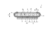
- FIG. 1A is a cross-sectional view illustrating an example of an electrochemical cell according to a first embodiment.
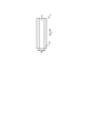
- FIG. 1B is a side view of an example of the electrochemical cell according to the first embodiment, as viewed from the air electrode side.
- FIG. 1C is a side view of an example of an electrochemical cell according to the first embodiment, as viewed from the interconnector side.
- FIG. 2A is a perspective view showing an example of an electrochemical cell device according to the first embodiment.
- FIG. 2B is a cross-sectional view taken along line XX shown in FIG. 2A.
- FIG. 2C is a top view illustrating an example of the electrochemical cell device according to the first embodiment.
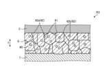
- FIG. 3 is an enlarged cross-sectional view of a region R1 shown in FIG. 1A.
- FIG. 4 is an external perspective view illustrating an example of a module according to the first embodiment.
- FIG. 5 is an exploded perspective view illustrating an example of a module housing device according to the first embodiment.
- FIG. 6A is a cross-sectional view showing an example of an electrochemical cell device according to the second embodiment.
- FIG. 6B is a cross-sectional view showing an electrochemical cell according to a second embodiment.
- FIG. 7 is an enlarged cross-sectional view of region R2 shown in FIG. 6B.
- FIG. 8 is a perspective view illustrating an example of an electrochemical cell according to the third embodiment.
- FIG. 9 is a partial cross-sectional view of the electrochemical cell shown in FIG.
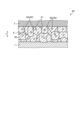
- FIG. 10 is an enlarged cross-sectional view of a region R3 shown in FIG. FIG.
- FIG. 11A is a cross-sectional view illustrating an example of an electrochemical cell according to a fourth embodiment.
- FIG. 11B is a cross-sectional view showing another example of the electrochemical cell according to the fourth embodiment.
- FIG. 11C is a cross-sectional view showing another example of the electrochemical cell according to the fourth embodiment.
- FIG. 12 is an enlarged cross-sectional view of a region R4 shown in FIG. 11A.
- the above-mentioned fuel cell stack device had room for improvement in terms of durability.
- the electrochemical cell device may include a cell stack having a plurality of electrochemical cells.
- An electrochemical cell device having a plurality of electrochemical cells will be simply referred to as a cell stack device.
- FIG. 1A is a cross-sectional view showing an example of an electrochemical cell according to the first embodiment.
- FIG. 1B is a side view of an example of an electrochemical cell according to the first embodiment, viewed from the air electrode side.
- FIG. 1C is a side view of an example of an electrochemical cell according to the first embodiment, viewed from the interconnector side. Note that FIGS. 1A to 1C show enlarged views of a portion of each component of the electrochemical cell.
- the electrochemical cell may also be simply referred to as a cell.
- cell 1 is a hollow flat plate-like elongated plate.
- the shape of cell 1 as a whole viewed from the side may be, for example, a rectangle with a side length in the length direction L of 5 cm to 50 cm and a length in the width direction W perpendicular to this length direction L of 1 cm to 10 cm.
- the overall thickness of cell 1 in the thickness direction T may be, for example, 1 mm to 5 mm.
- the cell 1 includes a conductive support substrate 2, an element section 3, and an interconnector 4.
- the support substrate 2 is columnar and has a pair of opposing flat surfaces, a first flat surface n1 and a second flat surface n2, and a pair of arc-shaped side surfaces m that connect the first flat surface n1 and the second flat surface n2.
- the element portion 3 is located on the first flat surface n1 of the support substrate 2.
- the element portion 3 has a fuel electrode 5 as a first electrode, a solid electrolyte layer 6, an intermediate layer 7, and an air electrode 8 as a second electrode.
- the air electrode 8 does not extend to the lower end of the cell 1.
- the air electrode 8 does not extend to the lower end of the cell 1.
- the interconnector 4 may extend to the lower end of the cell 1.
- the interconnector 4 and the solid electrolyte layer 6 are exposed on the surface.
- the solid electrolyte layer 6 is exposed on the surface of a pair of arc-shaped side surfaces m of the cell 1. The interconnector 4 does not have to extend to the lower end of the cell 1.
- the support substrate 2 has gas flow paths 2a therein through which gas flows.
- the example of the support substrate 2 shown in FIG. 1A has six gas flow paths 2a.
- the support substrate 2 has gas permeability, and allows the fuel gas flowing through the gas flow paths 2a to pass through to the fuel electrode 5.
- the support substrate 2 may be conductive.
- the conductive support substrate 2 collects electricity generated in the element section 3 to the interconnector 4.
- the material of the support substrate 2 includes, for example, an iron group metal component and an inorganic oxide.
- the iron group metal component may be, for example, Ni (nickel) and/or NiO.
- the inorganic oxide may be, for example, a specific rare earth element oxide.
- the rare earth element oxide may include, for example, one or more rare earth elements selected from Sc, Y, La, Nd, Sm, Gd, Dy, and Yb.
- the material of the fuel electrode 5 may be a generally known material.
- the fuel electrode 5 may be made of a porous conductive ceramic, such as a ceramic containing calcium oxide, magnesium oxide, or ZrO 2 in which a rare earth element oxide is dissolved, and Ni and/or NiO.
- the rare earth element oxide may contain a plurality of rare earth elements selected from Sc, Y, La, Ce, Nd, Sm, Gd, Dy, and Yb. Calcium oxide, magnesium oxide, or ZrO 2 in which a rare earth element oxide is dissolved may be referred to as stabilized zirconia.
- the stabilized zirconia may also include partially stabilized zirconia.
- the solid electrolyte layer 6 is an electrolyte and transfers ions between the fuel electrode 5 and the air electrode 8. At the same time, the solid electrolyte layer 6 has gas barrier properties, making it difficult for leakage of fuel gas and oxygen-containing gas to occur.
- the material of the solid electrolyte layer 6 may be, for example, ZrO 2 in which 3 mol % to 15 mol % of rare earth element oxide is dissolved.
- the rare earth element oxide may include, for example, one or more rare earth elements selected from Sc, Y, La, Ce, Nd, Sm, Gd, Dy, and Yb.
- the solid electrolyte layer 6 may include, for example, ZrO 2 in which Yb, Sc, or Gd is dissolved, or may include BaZrO 3 in which Sc, Y, or Yb is dissolved. Details of the solid electrolyte layer 6 will be described later.
- the intermediate layer 7 functions as a diffusion suppression layer.
- the intermediate layer 7 makes it difficult for elements such as Sr (strontium) contained in the air electrode 8, which will be described later, to diffuse into the solid electrolyte layer 6, thereby making it difficult for an electrically resistive layer such as SrZrO3 to form in the solid electrolyte layer 6.
- the material of the intermediate layer 7 is not particularly limited as long as it generally prevents diffusion of elements between the air electrode 8 and the solid electrolyte layer 6.
- the material of the intermediate layer 7 may contain, for example, cerium oxide (CeO 2 ) in which a rare earth element other than Ce (cerium) is dissolved.
- CeO 2 cerium oxide
- Gd gadolinium
- Sm sinarium
- the air electrode 8 is gas permeable.
- the open porosity of the air electrode 8 may be, for example, 20% or more, and particularly in the range of 30% to 50%.
- the material of the air electrode 8 may be, for example, a conductive ceramic such as a so-called ABO3 - type perovskite oxide.
- the material of the air electrode 8 may be, for example, a composite oxide in which Sr ( strontium ) and La (lanthanum) coexist at the A site.
- composite oxides include LaxSr1 - xCoyFe1 - yO3 , LaxSr1 - xMnO3 , LaxSr1 - xFeO3 , and LaxSr1 - xCoO3 , where x is 0 ⁇ x ⁇ 1 and y is 0 ⁇ y ⁇ 1.
- the interconnector 4 is dense, which makes it difficult for the fuel gas flowing through the gas flow passage 2a located inside the support substrate 2 and the oxygen-containing gas flowing outside the support substrate 2 to leak.
- the interconnector 4 may have a relative density of 93% or more, particularly 95% or more.
- Lanthanum chromite-based perovskite oxide LaCrO3 -based oxide
- lanthanum strontium titanium-based perovskite oxide LaSrTiO3 - based oxide
- These materials are conductive and are not easily reduced or oxidized even when in contact with a fuel gas such as a hydrogen-containing gas and an oxygen-containing gas such as air.
- FIG. 2A is a perspective view showing an example of the electrochemical cell device according to the first embodiment.
- Figure 2B is a cross-sectional view taken along line XX shown in Figure 2A.
- Figure 2C is a top view showing an example of the electrochemical cell device according to the first embodiment.
- the cell stack device 10 includes a cell stack 11 having a plurality of cells 1 arranged (stacked) in the thickness direction T of the cells 1 (see FIG. 1A), and a fixing member 12.
- the fixing member 12 has a fixing material 13 and a support member 14.
- the support member 14 supports the cell 1.
- the fixing material 13 fixes the cell 1 to the support member 14.
- the support member 14 also has a support body 15 and a gas tank 16.
- the support body 15 and the gas tank 16, which are the support member 14, are made of, for example, metal.
- the support 15 has insertion holes 15a into which the lower ends of the multiple cells 1 are inserted.
- the lower ends of the multiple cells 1 and the inner wall of the insertion holes 15a are joined with a fixing material 13.
- the gas tank 16 has an opening for supplying reactive gas to the multiple cells 1 through the insertion holes 15a, and a groove 16a located around the opening.
- the outer peripheral edge of the support 15 is joined to the gas tank 16 by a bonding material 21 filled in the groove 16a of the gas tank 16.
- fuel gas is stored in an internal space 22 (see FIG. 2B) formed by the support body 15, which is the support member 14, and the gas tank 16.
- a gas circulation pipe 20 is connected to the gas tank 16.
- the fuel gas is supplied to the gas tank 16 through this gas circulation pipe 20, and is supplied from the gas tank 16 to a gas flow path 2a (see FIG. 1A) inside the cell 1.
- the fuel gas supplied to the gas tank 16 is generated in a reformer 102 (see FIG. 4), which will be described later.
- Hydrogen-rich fuel gas can be produced by steam reforming the raw fuel.
- fuel gas is produced by steam reforming, the fuel gas contains water vapor.
- FIG. 2A has two rows of cell stacks 11, two supports 15, and a gas tank 16.
- Each of the two rows of cell stacks 11 has a plurality of cells 1.
- Each cell stack 11 is fixed to each support 15.
- the gas tank 16 has two through holes on the top surface.
- a support 15 is disposed in each through hole.
- the internal space 22 is formed by one gas tank 16 and two supports 15.
- the shape of the insertion hole 15a may be, for example, an oval shape when viewed from above.
- the length of the insertion hole 15a in the arrangement direction of the cells 1, i.e., the thickness direction T may be greater than the distance between the two end current collecting members 17 located at both ends of the cell stack 11.
- the width of the insertion hole 15a may be, for example, greater than the length of the cell 1 in the width direction W (see FIG. 1A).
- the joint between the inner wall of the insertion hole 15a and the lower end of the cell 1 is filled with a fixing material 13 and solidified. This bonds and fixes the inner wall of the insertion hole 15a to the lower end of each of the multiple cells 1, and also bonds and fixes the lower ends of the cells 1 to each other.
- the gas flow path 2a of each cell 1 communicates with the internal space 22 of the support member 14 at its lower end.
- the fixing material 13 and the bonding material 21 may be made of a material with low electrical conductivity, such as glass.
- Specific materials for the fixing material 13 and the bonding material 21 may include amorphous glass, and in particular, crystallized glass.
- any of SiO 2 -CaO based, MgO-B 2 O 3 based, La 2 O 3 -B 2 O 3 -MgO based, La 2 O 3 -B 2 O 3 -ZnO based, SiO 2 -CaO-ZnO based materials may be used, and in particular, SiO 2 -MgO based materials may be used.
- connection member 18 is interposed between adjacent cells 1 among the multiple cells 1.
- the connection member 18 electrically connects the fuel electrode 5 of one adjacent cell 1 to the air electrode 8 of the other cell 1 in series. More specifically, the connection member 18 connects the interconnector 4 electrically connected to the fuel electrode 5 of one adjacent cell 1 to the air electrode 8 of the other cell 1.
- an end current collecting member 17 is electrically connected to the cell 1 located on the outermost side in the arrangement direction of the multiple cells 1.
- the end current collecting member 17 is connected to a conductive part 19 that protrudes to the outside of the cell stack 11.
- the conductive part 19 collects electricity generated by power generation in the cell 1 and draws it out to the outside. Note that the end current collecting member 17 is not shown in FIG. 2A.
- the cell stack device 10 may be a single battery in which two cell stacks 11A, 11B are connected in series.
- the conductive portion 19 of the cell stack device 10 is divided into a positive terminal 19A, a negative terminal 19B, and a connection terminal 19C.
- the positive terminal 19A is the positive electrode when the power generated by the cell stack 11 is output to the outside, and is electrically connected to the positive end current collector 17 of the cell stack 11A.
- the negative terminal 19B is the negative electrode when the power generated by the cell stack 11 is output to the outside, and is electrically connected to the negative end current collector 17 of the cell stack 11B.
- connection terminal 19C electrically connects the end current collecting member 17 on the negative electrode side of the cell stack 11A to the end current collecting member 17 on the positive electrode side of the cell stack 11B.
- Fig. 3 is an enlarged cross-sectional view of a region R1 shown in Fig. 1A.
- the solid electrolyte layer 6 has a first surface 6a and a second surface 6b located at both ends in the thickness direction T.
- the first surface 6a is in contact with the fuel electrode 5.
- the second surface 6b is in contact with the intermediate layer 7.
- the solid electrolyte layer 6 has a plurality of electrolyte particles 60 and a plurality of pores 62. Each of the plurality of electrolyte particles 60 contains an oxide. Adjacent electrolyte particles 60 of the plurality of electrolyte particles 60 are separated by grain boundaries 61. The plurality of electrolyte particles 60 includes first particles and second particles.
- the multiple pores 62 include a first pore 62a and a second pore 62b.
- the first pore 62a is located outside the electrolyte particle 60, which is a first particle, and is in contact with the first particle.
- the first pore 62a is a pore 62 located at the grain boundary 61 in the cross section shown in FIG. 3, i.e., in the cross section of the solid electrolyte layer 6 intersecting the first surface 6a and the second surface 6b.
- the first pore 62a is in contact with two or more different first particles.
- the first particle may be in contact with two or more first pores 62a.
- the second pore 62b is a pore 62 located inside the electrolyte particle 60, which is a second particle.
- the second pore 62b is included inside one second particle.
- the second particle may include two or more second pores 62b.
- the first particle in contact with the first pore 62a may also serve as a second particle including the second pore 62b inside.
- the multiple electrolyte particles 60 may also include electrolyte particles 60 that are not in contact with the first pores 62a and do not include second pores 62b inside.
- the solid electrolyte layer 6 has a plurality of pores 62 including the first pores 62a and the second pores 62b, which makes it less likely to crack, peel, or the like due to thermal expansion and/or thermal contraction.
- the solid electrolyte layer 6 and the cell 1 having such a solid electrolyte layer 6 have improved durability, for example, compared to a case in which the plurality of pores 62 do not include the first pores 62a and the second pores 62b.
- the number of first pores 62a present in a unit area may be smaller than the number of second pores 62b.
- the number of first pores 62a present in a unit area may be 1/2 or less the number of second pores 62b.
- the solid electrolyte layer 6 and the cell 1 having such a solid electrolyte layer 6 are less likely to peel off at the grain boundaries 61 between adjacent electrolyte particles 60 compared to when the first pores 62a are more than the second pores 62b, and therefore durability is improved.
- the solid electrolyte layer 6 may have only the second pores 62b and not the first pores 62a.
- the first diameter when the average diameter of the first pores 62a is the first diameter and the average diameter of the second pores 62b is the second diameter, the first diameter may be smaller than the second diameter.
- the average diameters of the first pores 62a and the second pores 62b can be calculated based on the circle equivalent diameters obtained by observing the cross section of the solid electrolyte layer 6.
- the solid electrolyte layer 6 and the cell 1 having such a solid electrolyte layer 6 are less likely to peel off at the grain boundaries 61 compared to when the first diameter is larger than the second diameter, for example, and therefore the durability is improved.
- the first diameter which is the average diameter of the first pores 62a, may be, for example, 0.3 ⁇ m or less, and in particular 0.1 ⁇ m or more and 0.3 ⁇ m or less.
- the second diameter which is the average diameter of the second pores 62b, may be, for example, 1 ⁇ m or less, and in particular 0.4 ⁇ m or more and 0.7 ⁇ m or less.
- the multiple pores 62 may have an area ratio of 2% or less. This makes it difficult for ions to be impeded from moving in the thickness direction T inside the solid electrolyte layer 6, improving ion conductivity, for example. Furthermore, a cell 1 having such a solid electrolyte layer 6 improves power generation performance, for example.
- the multiple pores 62 may have an area ratio of 0.3% or more. This makes it possible to obtain a solid electrolyte layer 6 and cell 1 with high durability.
- the average thickness t of the solid electrolyte layer 6 can be calculated using a cross-sectional photograph of the solid electrolyte layer 6.
- the arrangement and diameter of the multiple pores 62 in the solid electrolyte layer 6 can be confirmed and calculated by analyzing a cross section of the solid electrolyte layer 6 intersecting the first surface 6a and the second surface 6b.
- a cross-sectional photograph of the solid electrolyte layer 6 is taken with an SEM at a magnification of, for example, 5000 times.
- the cross-sectional photograph is subjected to image analysis to calculate the diameters of the first pores 62a and the second pores 62b located in a region having 200 or more electrolyte particles 60 between the first surface 6a and the second surface 6b.
- the diameters of the first pores 62a and the second pores 62b are calculated by measuring the areas of the first pores 62a and the second pores 62b using, for example, image analysis software and converting the areas into circle equivalent diameters.
- a square having sides each equal to the average thickness t of the solid electrolyte layer 6 may be used as a unit area, and the number of first pores 62a and second pores 62b present in this unit area may be counted.
- Fig. 4 is an external perspective view showing an example of a module according to a first embodiment.
- Fig. 4 shows a state in which the front and rear surfaces, which are part of the storage container 101, have been removed and the cell stack device 10 of the fuel cell stored therein has been removed to the rear.
- the module 100 includes a storage container 101 and a cell stack device 10 stored in the storage container.
- a reformer 102 is disposed above the cell stack device 10.
- the reformer 102 reforms raw fuel such as natural gas or kerosene to generate fuel gas, which is then supplied to the cell 1.
- the raw fuel is supplied to the reformer 102 through a raw fuel supply pipe 103.
- the reformer 102 may also include a vaporizer 102a that vaporizes water, and a reformer 102b.
- the reformer 102b includes a reforming catalyst (not shown) and reforms the raw fuel into fuel gas.
- Such a reformer 102 can perform steam reforming, which is a highly efficient reforming reaction.
- the fuel gas generated in the reformer 102 is then supplied to the gas flow path 2a (see Figure 1A) of the cell 1 through the gas flow pipe 20, the gas tank 16, and the support member 14.
- the temperature inside the module 100 during normal power generation is approximately 500°C to 1000°C due to the combustion of gas and power generation by the cell 1.
- the module 100 can be configured to house a cell stack device 10 having cells 1 whose performance is improved, thereby making it possible to make the module 100 have improved performance.
- Fig. 5 is an exploded perspective view that illustrates an example of a module housing device according to the first embodiment.
- the module housing device 110 according to this embodiment includes an outer case 111, the module 100 illustrated in Fig. 4, and auxiliary equipment (not illustrated).
- the auxiliary equipment operates the module 100.
- the module 100 and the auxiliary equipment are housed in the outer case 111. Note that some components are omitted in Fig. 5.
- the exterior case 111 of the module accommodating device 110 shown in Figure 5 has support posts 112 and an exterior plate 113.
- a partition plate 114 divides the interior of the exterior case 111 into upper and lower sections.
- the space above the partition plate 114 in the exterior case 111 is a module accommodating chamber 115 that accommodates the module 100, and the space below the partition plate 114 in the exterior case 111 is an auxiliary equipment accommodating chamber 116 that accommodates the auxiliary equipment that operates the module 100. Note that in Figure 5, the auxiliary equipment accommodated in the auxiliary equipment accommodating chamber 116 is omitted.
- the partition plate 114 also has an air flow port 117 for allowing air from the auxiliary equipment housing chamber 116 to flow toward the module housing chamber 115.
- the exterior plate 113 that constitutes the module housing chamber 115 has an exhaust port 118 for exhausting air from within the module housing chamber 115.
- the module housing device 110 by providing the module 100 with improved performance in the module housing chamber 115, the module housing device 110 can be made to have improved performance.
- a hollow flat support substrate is used, but the present invention can also be applied to a cell stack device that uses a cylindrical support substrate.
- FIG. 6A Second Embodiment Next, an electrochemical cell and an electrochemical cell device according to a second embodiment will be described with reference to FIGS. 6A to 7.
- FIG. 6A Second Embodiment
- a so-called “vertical stripe type” in which only one element part including a fuel electrode, a solid electrolyte layer, and an air electrode is provided on the surface of a support substrate is exemplified, but the present invention can also be applied to a horizontal stripe type electrochemical cell device in which so-called “horizontal stripe type” electrochemical cells are arranged in which element parts are provided at multiple locations spaced apart from each other on the surface of a support substrate and adjacent element parts are electrically connected.
- FIG. 6A is a cross-sectional view showing an example of an electrochemical cell device according to the second embodiment.
- FIG. 6B is a cross-sectional view showing an electrochemical cell according to the second embodiment.
- FIG. 7 is an enlarged view of region R2 shown in FIG. 6B.
- multiple cells 1A extend in the length direction L from a pipe 22a that circulates fuel gas.
- the cells 1A have multiple element parts 3 on a support substrate 2. Inside the support substrate 2, a gas flow path 2a is provided through which the fuel gas flows from the pipe 22a.
- the cells 1A are also electrically connected to each other via connection members 31.
- the connection members 31 are located between the element portions 3 of the cells 1A, and connect the adjacent cells 1A.
- the cell 1A includes a support substrate 2, a pair of element portions 3, and a sealing portion 30.
- the support substrate 2 is columnar and has a pair of opposing flat surfaces, a first flat surface n1 and a second flat surface n2, and a pair of arc-shaped side surfaces m connecting the first flat surface n1 and the second flat surface n2.
- the pair of element portions 3 are positioned so as to face each other on the first flat surface n1 and the second flat surface n2 of the support substrate 2.
- the sealing portion 30 is positioned so as to cover the side surface m of the support substrate 2.
- the solid electrolyte layer 6 has a plurality of electrolyte particles 60 and a plurality of pores 62.
- Each of the plurality of electrolyte particles 60 contains an oxide. Adjacent electrolyte particles 60 among the plurality of electrolyte particles 60 are separated by grain boundaries 61.
- the plurality of electrolyte particles 60 includes first particles and second particles.
- the multiple pores 62 include first pores 62a that are adjacent to the first particles and located at the grain boundaries 61, and second pores 62b that are located inside the second particles.
- the solid electrolyte layer 6 has a plurality of pores 62 including the first pores 62a and the second pores 62b, which makes it less susceptible to cracks, peeling, and the like that accompany thermal expansion and/or thermal contraction.
- the solid electrolyte layer 6 and the cell 1A having such a solid electrolyte layer 6 have improved durability, for example, compared to a case in which the plurality of pores 62 do not include the first pores 62a and the second pores 62b.
- the number of first pores 62a present per unit area may be fewer than the number of second pores 62b.
- the number of first pores 62a present per unit area may be half or less the number of second pores 62b. This improves durability of the solid electrolyte layer 6 and the cell 1A having such a solid electrolyte layer 6, since adjacent electrolyte particles 60 are less likely to peel off at the grain boundaries 61, compared to when the number of first pores 62a is greater than the number of second pores 62b.
- Fig. 8 is a perspective view showing an example of an electrochemical cell according to the third embodiment
- Fig. 9 is a partial cross-sectional view of the electrochemical cell shown in Fig. 8.
- cell 1B has an element section 3B in which a fuel electrode 5, a solid electrolyte layer 6, an intermediate layer 7, and an air electrode 8 are stacked, and conductive members 91, 92.
- a fuel electrode 5 a solid electrolyte layer 6, an intermediate layer 7, and an air electrode 8 are stacked
- conductive members 91, 92 are electrically connected by conductive members 91, 92, which are adjacent metal layers.
- the conductive members 91, 92 electrically connect adjacent cells 1B to each other, and have a gas flow path that supplies gas to the fuel electrode 5 or the air electrode 8.
- cell 1B has a sealing material that hermetically seals the fuel gas flow path and the oxygen-containing gas flow path of the flat cell stack.
- the sealing material is a fixing member 96 for the cell, and has a bonding material 93 and support members 94, 95 that are frames.
- the bonding material 93 may be glass or a metal material such as silver solder.
- the support member 94 may be a so-called separator that separates the fuel gas flow path from the oxygen-containing gas flow path.
- the material of the support members 94, 95 may be, for example, a conductive metal or an insulating ceramic. Either or both of the support members 94, 95 may be made of an insulating material. If the support member 94 is made of metal, the support member 94 may be integrated with the conductive member 92. If the support member 95 is made of metal, the support member 95 may be integrated with the conductive member 91.
- One of the support members 94, 95 is insulating, electrically insulating the two conductive members 91, 92 that sandwich the flat cell from each other.
- FIG. 10 is an enlarged cross-sectional view of region R3 shown in FIG. 9.
- the solid electrolyte layer 6 has a plurality of electrolyte particles 60 and a plurality of pores 62.
- Each of the plurality of electrolyte particles 60 contains an oxide.
- adjacent electrolyte particles 60 are separated by grain boundaries 61.
- the plurality of electrolyte particles 60 include first particles and second particles.
- the multiple pores 62 include first pores 62a that are adjacent to the first particles and located at the grain boundaries 61, and second pores 62b that are located inside the second particles.
- the solid electrolyte layer 6 has a plurality of pores 62 including the first pores 62a and the second pores 62b, which makes it less likely to crack, peel, or the like due to thermal expansion and/or thermal contraction.
- the solid electrolyte layer 6 and the cell 1B having such a solid electrolyte layer 6 have improved durability, compared to a case in which the plurality of pores 62 do not include the first pores 62a and the second pores 62b.
- the number of first pores 62a present per unit area may be fewer than the number of second pores 62b.
- the number of first pores 62a present per unit area may be half or less the number of second pores 62b. This improves durability of the solid electrolyte layer 6 and the cell 1B having such a solid electrolyte layer 6, since adjacent electrolyte particles 60 are less likely to peel off at the grain boundaries 61, compared to when the number of first pores 62a is greater than the number of second pores 62b.
- Fig. 11A is a cross-sectional view showing an example of an electrochemical cell according to the fourth embodiment.
- Fig. 11B and Fig. 11C are cross-sectional views showing another example of an electrochemical cell according to the fourth embodiment.
- Fig. 12 is an enlarged view of a region R4 shown in Fig. 11A.
- Fig. 12 can also be applied to the examples of Fig. 11B and Fig. 11C.
- the cell 1C has an element section 3C in which a fuel electrode 5, a solid electrolyte layer 6, an intermediate layer 7, and an air electrode 8 are laminated, and a support substrate 2.
- the support substrate 2 has a through hole or a fine hole at a portion in contact with the element section 3C, and has a member 120 located outside the gas flow path 2a.
- the support substrate 2 can circulate gas between the gas flow path 2a and the element section 3C.
- the support substrate 2 may be composed of, for example, one or more metal plates.
- the material of the metal plate may contain chromium.
- the metal plate may have a conductive coating layer.
- the support substrate 2 electrically connects adjacent cells 1C to each other.
- the element section 3C may be formed directly on the support substrate 2, or may be bonded to the support substrate 2 by a bonding material.
- the side of the fuel electrode 5 is covered with a solid electrolyte layer 6, which airtightly seals the gas flow path 2a through which the fuel gas flows.
- the side of the fuel electrode 5 may be covered and sealed with a dense glass or ceramic sealing material 9.
- the sealing material 9 that covers the side of the fuel electrode 5 may have electrical insulating properties.
- gas flow path 2a of the support substrate 2 may be formed by a member 120 having projections and recesses as shown in FIG. 11C.
- the solid electrolyte layer 6 has a plurality of electrolyte particles 60 and a plurality of pores 62.
- Each of the plurality of electrolyte particles 60 contains an oxide. Adjacent electrolyte particles 60 among the plurality of electrolyte particles 60 are separated by grain boundaries 61.
- the plurality of electrolyte particles 60 includes first particles and second particles.
- the multiple pores 62 include first pores 62a that are adjacent to the first particles and located at the grain boundaries 61, and second pores 62b that are located inside the second particles.
- the solid electrolyte layer 6 has a plurality of pores 62 including the first pores 62a and the second pores 62b, which makes it less likely to crack, peel, or the like due to thermal expansion and/or thermal contraction.
- the solid electrolyte layer 6 and the cell 1C having such a solid electrolyte layer 6 have improved durability compared to, for example, a case in which the plurality of pores 62 does not include the first pores 62a and the second pores 62b.
- the number of first pores 62a present per unit area may be fewer than the number of second pores 62b.
- the number of first pores 62a present per unit area may be half or less the number of second pores 62b. This improves durability of the solid electrolyte layer 6 and the cell 1C having such a solid electrolyte layer 6, since adjacent electrolyte particles 60 are less likely to peel off at the grain boundaries 61, compared to when the number of first pores 62a is greater than the number of second pores 62b.
- a fuel cell, a fuel cell stack device, a fuel cell module, and a fuel cell device are shown as examples of an “electrochemical cell,” “electrochemical cell device,” “module,” and “module housing device,” but other examples may be an electrolytic cell, an electrolytic cell stack device, an electrolytic module, and an electrolytic device, respectively.
- the electrolytic cell has a first electrode and a second electrode, and decomposes water vapor into hydrogen and oxygen, or carbon dioxide into carbon monoxide and oxygen, when supplied with electric power.
- an oxide ion conductor or a hydrogen ion conductor is shown as an example of the electrolyte material of the electrochemical cell, but a hydroxide ion conductor may also be used.
- Such an electrolytic cell, an electrolytic cell stack device, an electrolytic module, and an electrolytic device can improve durability.
- the solid electrolyte layer has a plurality of electrolyte particles including an oxide and a plurality of pores; the plurality of electrolyte particles includes first particles and second particles; the plurality of pores includes first pores and second pores, the first pore is in contact with the first particle, The second pores are located inside the second particles.
- the number of the first pores per unit area may be smaller than the number of the second pores in a cross section of the solid electrolyte layer.
- the number of the first pores present in the unit area may be 1/2 or less of the number of the second pores.
- a first diameter which is the average diameter of the first pores
- a second diameter which is the average diameter of the second pores
- the second diameter may be 1 ⁇ m or less.
- the first diameter may be 0.3 ⁇ m or less.
- the area ratio of the plurality of pores in a cross section of the solid electrolyte layer may be 2% or less.
- the (8) electrochemical cell includes any one of the solid electrolyte layers (1) to (7) above.
- the (9) electrochemical cell device has a cell stack including the electrochemical cell (8) described above.
- the module (10) comprises the electrochemical cell device (9) described above, and a container for housing the electrochemical cell device.
- the module housing device (11) includes the module (10) and Auxiliary equipment for operating the module; and an exterior case that houses the module and the auxiliary equipment.
Landscapes
- Chemical & Material Sciences (AREA)
- Engineering & Computer Science (AREA)
- Electrochemistry (AREA)
- Chemical Kinetics & Catalysis (AREA)
- Manufacturing & Machinery (AREA)
- Sustainable Development (AREA)
- Sustainable Energy (AREA)
- Life Sciences & Earth Sciences (AREA)
- General Chemical & Material Sciences (AREA)
- Materials Engineering (AREA)
- Metallurgy (AREA)
- Organic Chemistry (AREA)
- Inorganic Chemistry (AREA)
- Fuel Cell (AREA)
- Electrolytic Production Of Non-Metals, Compounds, Apparatuses Therefor (AREA)
Priority Applications (3)
| Application Number | Priority Date | Filing Date | Title |
|---|---|---|---|
| EP24832045.9A EP4715914A1 (en) | 2023-06-29 | 2024-06-27 | Solid electrolyte layer, electrochemical cell, electrochemical cell device, module, and module storage device |
| JP2024566436A JP7657386B1 (ja) | 2023-06-29 | 2024-06-27 | 固体電解質層、電気化学セル、電気化学セル装置、モジュールおよびモジュール収容装置 |
| JP2025049434A JP2025102842A (ja) | 2023-06-29 | 2025-03-25 | 固体電解質層、電気化学セル、電気化学セル装置、モジュールおよびモジュール収容装置 |
Applications Claiming Priority (2)
| Application Number | Priority Date | Filing Date | Title |
|---|---|---|---|
| JP2023107240 | 2023-06-29 | ||
| JP2023-107240 | 2023-06-29 |
Publications (1)
| Publication Number | Publication Date |
|---|---|
| WO2025005186A1 true WO2025005186A1 (ja) | 2025-01-02 |
Family
ID=93939190
Family Applications (1)
| Application Number | Title | Priority Date | Filing Date |
|---|---|---|---|
| PCT/JP2024/023354 Ceased WO2025005186A1 (ja) | 2023-06-29 | 2024-06-27 | 固体電解質層、電気化学セル、電気化学セル装置、モジュールおよびモジュール収容装置 |
Country Status (3)
| Country | Link |
|---|---|
| EP (1) | EP4715914A1 (https=) |
| JP (2) | JP7657386B1 (https=) |
| WO (1) | WO2025005186A1 (https=) |
Citations (8)
| Publication number | Priority date | Publication date | Assignee | Title |
|---|---|---|---|---|
| JPH04170363A (ja) * | 1990-10-31 | 1992-06-18 | Tonen Corp | 多結晶焼結体固体電解質 |
| JP2000044340A (ja) * | 1998-07-24 | 2000-02-15 | Tokyo Gas Co Ltd | ランタンガレート系焼結体およびその製造方法、ならびにそれを固体電解質として用いた燃料電池 |
| JP2004139936A (ja) * | 2002-10-21 | 2004-05-13 | Shinko Electric Ind Co Ltd | 燃料電池 |
| JP2010232094A (ja) * | 2009-03-27 | 2010-10-14 | Dainippon Printing Co Ltd | 単室型固体酸化物形燃料電池 |
| WO2013031961A1 (ja) | 2011-08-31 | 2013-03-07 | 京セラ株式会社 | 固体酸化物形燃料電池セル、セルスタック装置、燃料電池モジュールおよび燃料電池装置 |
| JP2015046365A (ja) | 2013-08-29 | 2015-03-12 | 京セラ株式会社 | セル、セルスタック装置、モジュールおよびモジュール収納装置 |
| JP2019220460A (ja) * | 2018-06-15 | 2019-12-26 | 日本碍子株式会社 | 電気化学セル用電解質、及び電気化学セル |
| JP2022038934A (ja) * | 2020-08-27 | 2022-03-10 | 日本特殊陶業株式会社 | 電気化学セル |
Family Cites Families (2)
| Publication number | Priority date | Publication date | Assignee | Title |
|---|---|---|---|---|
| JP3248182B2 (ja) * | 1990-06-15 | 2002-01-21 | 東ソー株式会社 | ジルコニア粉末及び焼結体並びにそれらの製造方法 |
| EP3978440A4 (en) * | 2019-05-29 | 2023-07-05 | National Institute Of Advanced Industrial Science And Technology | Impregnatable high-density, brittle material structure |
-
2024
- 2024-06-27 EP EP24832045.9A patent/EP4715914A1/en active Pending
- 2024-06-27 JP JP2024566436A patent/JP7657386B1/ja active Active
- 2024-06-27 WO PCT/JP2024/023354 patent/WO2025005186A1/ja not_active Ceased
-
2025
- 2025-03-25 JP JP2025049434A patent/JP2025102842A/ja active Pending
Patent Citations (8)
| Publication number | Priority date | Publication date | Assignee | Title |
|---|---|---|---|---|
| JPH04170363A (ja) * | 1990-10-31 | 1992-06-18 | Tonen Corp | 多結晶焼結体固体電解質 |
| JP2000044340A (ja) * | 1998-07-24 | 2000-02-15 | Tokyo Gas Co Ltd | ランタンガレート系焼結体およびその製造方法、ならびにそれを固体電解質として用いた燃料電池 |
| JP2004139936A (ja) * | 2002-10-21 | 2004-05-13 | Shinko Electric Ind Co Ltd | 燃料電池 |
| JP2010232094A (ja) * | 2009-03-27 | 2010-10-14 | Dainippon Printing Co Ltd | 単室型固体酸化物形燃料電池 |
| WO2013031961A1 (ja) | 2011-08-31 | 2013-03-07 | 京セラ株式会社 | 固体酸化物形燃料電池セル、セルスタック装置、燃料電池モジュールおよび燃料電池装置 |
| JP2015046365A (ja) | 2013-08-29 | 2015-03-12 | 京セラ株式会社 | セル、セルスタック装置、モジュールおよびモジュール収納装置 |
| JP2019220460A (ja) * | 2018-06-15 | 2019-12-26 | 日本碍子株式会社 | 電気化学セル用電解質、及び電気化学セル |
| JP2022038934A (ja) * | 2020-08-27 | 2022-03-10 | 日本特殊陶業株式会社 | 電気化学セル |
Also Published As
| Publication number | Publication date |
|---|---|
| JPWO2025005186A1 (https=) | 2025-01-02 |
| JP2025102842A (ja) | 2025-07-08 |
| EP4715914A1 (en) | 2026-03-25 |
| JP7657386B1 (ja) | 2025-04-04 |
Similar Documents
| Publication | Publication Date | Title |
|---|---|---|
| JP7453485B1 (ja) | 電気化学セル、電気化学セル装置、モジュールおよびモジュール収容装置 | |
| JP7672999B2 (ja) | 電気化学セル、電気化学セル装置、モジュールおよびモジュール収容装置 | |
| WO2022092235A1 (ja) | セル、セルスタック装置、モジュールおよびモジュール収容装置 | |
| JP7692059B2 (ja) | 電気化学セル装置、モジュールおよびモジュール収容装置 | |
| JP7657386B1 (ja) | 固体電解質層、電気化学セル、電気化学セル装置、モジュールおよびモジュール収容装置 | |
| JP7794994B2 (ja) | 電気化学セル、電気化学セル装置、モジュールおよびモジュール収容装置 | |
| JP7583227B2 (ja) | 電気化学セル、電気化学セル装置、モジュールおよびモジュール収容装置 | |
| JP7736801B2 (ja) | 電気化学セル、電気化学セル装置、モジュールおよびモジュール収容装置 | |
| JP7525759B1 (ja) | 固体電解質層、電気化学セル、電気化学セル装置、モジュールおよびモジュール収容装置 | |
| JP7543601B1 (ja) | 導電部材、電気化学セル装置、モジュールおよびモジュール収容装置 | |
| JP7736802B2 (ja) | 導電部材、電気化学セル、電気化学セル装置、モジュールおよびモジュール収容装置 | |
| JP7664714B2 (ja) | セル、セルスタック装置、モジュールおよびモジュール収容装置 | |
| EP4489151A1 (en) | Electrochemical cell, electrochemical cell device, module, and module accommodating device | |
| WO2024150829A1 (ja) | 電気化学セル、電気化学セル装置、モジュールおよびモジュール収容装置 | |
| WO2026029158A1 (ja) | 電気化学セル、電気化学セル装置、モジュールおよびモジュール収容装置 | |
| WO2024143355A1 (ja) | 電気化学セル、電気化学セル装置、モジュールおよびモジュール収容装置 | |
| WO2024247989A1 (ja) | 電気化学セル、電気化学セル装置、モジュールおよびモジュール収容装置 | |
| WO2025094956A1 (ja) | 電気化学セル、電気化学セル装置、モジュールおよびモジュール収容装置 | |
| JP2024048859A (ja) | 電気化学セル装置、モジュールおよびモジュール収容装置 | |
| WO2026048889A1 (ja) | 電気化学セル、電気化学セル装置、モジュールおよびモジュール収容装置 | |
| WO2024117052A1 (ja) | 複合部材、電気化学セル、電気化学セル装置、モジュールおよびモジュール収容装置 | |
| WO2025070717A1 (ja) | 電気化学セル、電気化学セル装置、モジュールおよびモジュール収容装置 | |
| JP2026008859A (ja) | 電気化学セル、電気化学セル装置、モジュールおよびモジュール収容装置 | |
| WO2024225476A1 (ja) | 固体電解質層、電気化学セル、電気化学セル装置、モジュールおよびモジュール収容装置 | |
| WO2024162413A1 (ja) | 固体電解質層、電気化学セル、電気化学セル装置、モジュールおよびモジュール収容装置 |
Legal Events
| Date | Code | Title | Description |
|---|---|---|---|
| WWE | Wipo information: entry into national phase |
Ref document number: 2024566436 Country of ref document: JP |
|
| 121 | Ep: the epo has been informed by wipo that ep was designated in this application |
Ref document number: 24832045 Country of ref document: EP Kind code of ref document: A1 |
|
| WWE | Wipo information: entry into national phase |
Ref document number: 2024832045 Country of ref document: EP |
|
| ENP | Entry into the national phase |
Ref document number: 2024832045 Country of ref document: EP Effective date: 20251218 |
|
| ENP | Entry into the national phase |
Ref document number: 2024832045 Country of ref document: EP Effective date: 20251218 |
|
| ENP | Entry into the national phase |
Ref document number: 2024832045 Country of ref document: EP Effective date: 20251218 |
|
| NENP | Non-entry into the national phase |
Ref country code: DE |
|
| ENP | Entry into the national phase |
Ref document number: 2024832045 Country of ref document: EP Effective date: 20251218 |
|
| ENP | Entry into the national phase |
Ref document number: 2024832045 Country of ref document: EP Effective date: 20251218 |
|
| WWP | Wipo information: published in national office |
Ref document number: 2024832045 Country of ref document: EP |