WO2025005155A1 - 燃料電池装置 - Google Patents
燃料電池装置 Download PDFInfo
- Publication number
- WO2025005155A1 WO2025005155A1 PCT/JP2024/023252 JP2024023252W WO2025005155A1 WO 2025005155 A1 WO2025005155 A1 WO 2025005155A1 JP 2024023252 W JP2024023252 W JP 2024023252W WO 2025005155 A1 WO2025005155 A1 WO 2025005155A1
- Authority
- WO
- WIPO (PCT)
- Prior art keywords
- control
- fuel cell
- temperature
- fuel
- fuel gas
- Prior art date
- Legal status (The legal status is an assumption and is not a legal conclusion. Google has not performed a legal analysis and makes no representation as to the accuracy of the status listed.)
- Ceased
Links
Images



Classifications
-
- Y—GENERAL TAGGING OF NEW TECHNOLOGICAL DEVELOPMENTS; GENERAL TAGGING OF CROSS-SECTIONAL TECHNOLOGIES SPANNING OVER SEVERAL SECTIONS OF THE IPC; TECHNICAL SUBJECTS COVERED BY FORMER USPC CROSS-REFERENCE ART COLLECTIONS [XRACs] AND DIGESTS
- Y02—TECHNOLOGIES OR APPLICATIONS FOR MITIGATION OR ADAPTATION AGAINST CLIMATE CHANGE
- Y02E—REDUCTION OF GREENHOUSE GAS [GHG] EMISSIONS, RELATED TO ENERGY GENERATION, TRANSMISSION OR DISTRIBUTION
- Y02E60/00—Enabling technologies; Technologies with a potential or indirect contribution to GHG emissions mitigation
- Y02E60/30—Hydrogen technology
- Y02E60/50—Fuel cells
Definitions
- This disclosure relates to a fuel cell device.
- a fuel cell device comprises: A fuel cell that generates electricity using a fuel gas and air; a supply device for supplying a fuel gas to the fuel cell; a combustion section for combusting unreacted fuel gas in the fuel cell; a reformer located in a first direction from the combustion section and accommodating a reforming catalyst that is heated by heat generated by combustion in the combustion section; and a control device that executes a first control to reduce the amount of the fuel gas supplied to the fuel cell when the temperature of the combustion section is equal to or higher than a first temperature, and executes a second control in priority to the first control to increase the amount of the fuel gas supplied to the fuel cell when the temperature of the fuel cell is lower than a second temperature or when the temperature of the fuel cell is expected to drop to or below the second temperature.
- FIG. 1 is a diagram showing a schematic configuration of a fuel cell device according to an embodiment of the present invention
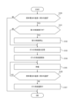
- 2 is a flowchart for explaining a heating process executed by the control device of FIG. 1
- 4 is a flowchart for explaining an overheating prevention process executed by the control device of FIG. 1
- 2 is a flowchart for explaining a heating process executed by the control device of FIG. 1 .
- a fuel cell device 10 includes a fuel cell 11, a first supply device (supply device) 12, a combustion section 13, a reformer 14, and a control device 15.
- the fuel cell device 10 may further include a first temperature sensor 16, a second temperature sensor 17, a second supply device 18, and a third supply device 19.
- the fuel cell 11 generates electricity through an electrochemical reaction using fuel gas and air.
- the fuel cell 11 may include a fuel cell.
- the fuel cell 11 may include a plurality of fuel cell cells.
- the plurality of fuel cell cells may form a cell stack.
- the cell stack may have any shape, for example, a hollow plate, a flat plate, a metal support, a cylinder, etc.
- the fuel cell may be a solid oxide fuel cell. In the fuel cell 11, all of the fuel gas and oxygen gas in the air may not undergo an electrochemical reaction, and unreacted fuel gas and oxygen gas may be discharged.
- the first supply device 12 directly or indirectly supplies fuel gas to the fuel cell 11.
- the first supply device 12, for example, supplies raw fuel to the reformer 14, thereby supplying fuel gas obtained by reforming the raw fuel as described below to the fuel cell 11.
- the first supply device 12 may directly or indirectly adjust the amount of fuel gas supplied to the fuel cell 11.
- the first supply device 12 may, for example, be a pump capable of changing the duty ratio.
- the combustion unit 13 burns the unreacted fuel gas in the fuel cell 11 using unreacted oxygen gas.
- the combustion unit 13 can heat the reformer 14 using the heat generated by burning the unreacted fuel gas.
- the combustion unit 13 may heat the reformer 14 to provide energy for causing a steam reforming reaction in the reformer 14.
- the reformer 14 is located in a first direction from the combustion section 13. In the fuel cell device 10, the first direction is a direction that is assumed to be oriented vertically upward when the fuel cell device 10 is installed.
- the reformer 14 contains a reforming catalyst.
- the reforming catalyst may generate fuel gas by steam reforming using raw fuel and steam.
- the reforming catalyst is heated by heat generated by combustion in the combustion section 13 to carry out a steam reforming reaction.
- a Ru-based catalyst may be used as the reforming catalyst.
- the raw fuel includes light hydrocarbons such as methane, ethane, propane, and butane.
- the raw fuel is, for example, city gas, LPG, biogas, etc., which include the light hydrocarbons.
- the water vapor may be supplied to the reformer 14 as liquid reforming water and vaporized into water vapor in a vaporization section provided in the reformer 14.
- the fuel gas includes, for example, hydrogen gas.
- the first temperature sensor 16 may detect the temperature of the combustion section 13.
- the second temperature sensor 17 may detect the temperature of the fuel cell 11.
- the first temperature sensor 16 and the second temperature sensor 17 are, for example, thermocouples.
- the second supply device 18 may adjust the amount of water supplied to the water reformer 14.
- the second supply device 18 may be, for example, a pump with a variable duty ratio.
- the third supply device 19 may adjust the amount of air supplied to the fuel cell 11.
- the third supply device 19 may be, for example, a blower with a variable duty ratio.
- the control device 15 is configured to include at least one processor, at least one dedicated circuit, or a combination of these.
- the processor is a general-purpose processor such as a CPU (Central Processing Unit) or a GPU (Graphics Processing Unit), or a dedicated processor specialized for specific processing.
- the dedicated circuit may be, for example, an FPGA (Field-Programmable Gate Array), an ASIC (Application Specific Integrated Circuit), etc.
- the control device 15 may control the operation of the fuel cell device 10.
- the control device 15 may control each part of the fuel cell device 10, for example, the voltage or current of the fuel cell 11, and the supply amount from the first supply device 12, the second supply device 18, and the third supply device 19, to generate power of the current value of the required load.
- the supply amount may mean the flow rate, i.e. the amount flowing per short period of time.
- the control device 15 executes a first control, a second control, a third control, and a fourth control.
- the control device 15 controls the first supply device 12 to reduce the amount of fuel gas supplied to the fuel cell 11.
- the control device 15 controls the first supply device 12 to increase the amount of fuel gas supplied to the fuel cell 11.
- the control device 15 may execute a third control under conditions different from the second control and the fourth control, as described below, and in the third control, the control device 15 controls the first supply device 12 to increase the amount of fuel gas supplied to the fuel cell 11.
- the control device 15 executes the first control when the temperature of the combustion section 13 is equal to or higher than the first temperature.
- the first temperature is set to a temperature that can suppress deterioration of the reforming catalyst.
- the first temperature may be set according to the type of reforming catalyst, and is, for example, 700 to 750°C for the above-mentioned Ru-based catalyst.
- the control device 15 may execute the first control when the current of the power generated by the fuel cell 11 is equal to or lower than the current threshold.
- the control device 15 may acquire the current of the power generated by the fuel cell 11 as information from a current sensor or an external device.
- the control device 15 may acquire the current from, for example, a current sensor built into the fuel cell device 10 or a current sensor provided outside the fuel cell device 10.
- the control device 15 may also acquire the current of the power generated by the fuel cell 11 from, for example, another information processing device.
- the control device 15 executes the second control in priority over the first control. In other words, even if the temperature of the combustion section 13 is higher than the first temperature, if the temperature of the fuel cell 11 is lower than the second temperature, or if the temperature of the fuel cell 11 is expected to drop below the second temperature, the control device 15 executes the second control without executing the first control.
- the second temperature may be determined, for example, based on the temperature of the fuel cell 11 when the fuel cell device 10 starts generating electricity.
- the drop in temperature of the fuel cell 11 below the second temperature may occur, for example, when the necessary fuel gas is not supplied to the fuel cell 11 due to an error in the gas flow meter or a gas leak caused by a crack in the fuel cell 11. Furthermore, if the necessary fuel gas is not supplied to the fuel cell 11, a misfire occurs and the temperature of the combustion section 13 drops. Therefore, if the drop in the temperature of the combustion section 13 detected by the first temperature sensor 16 continues, it can be expected that the fuel cell 11 will drop below the second temperature.
- the control device 15 may execute a third control if the temperature of the combustion section 13 falls below the first temperature after execution of the first control.
- the control device 15 may increase the fuel gas so that the increase in the fuel gas in the third control is less than the decrease in the fuel gas in the first control executed immediately before the third control.
- control device 15 may increase the fuel gas so that the time for which the fuel gas is increased in the third control is less than the time for which the fuel gas was decreased in the first control executed immediately before the third control.
- the absolute value of the increase in the amount of fuel gas supply in the third control in other words the increase in the flow rate
- the absolute value of the decrease in the amount of fuel gas supply in the first control in other words the decrease in the flow rate
- control device 15 may increase the fuel gas so that the time for which the fuel gas is increased in the third control is equal to or longer than the time for which the fuel gas was decreased in the first control executed immediately before the third control.
- the absolute value of the increase in the amount of fuel gas supply in the third control may be greater than the absolute value of the decrease in the amount of fuel gas supply in the first control.
- the control device 15 may also execute the fourth control in priority over the first control until a predetermined time has elapsed since the fuel cell 11 started generating electricity.
- the control device 15 may return the increased amount of fuel gas supply to the original amount.
- the heating process executed by the control device 15 in this embodiment will be described with reference to the flowchart in FIG. 2.
- the heating process is started, for example, periodically while the fuel cell device 10 is in operation.
- step S100 the control device 15 determines whether the temperature of the fuel cell 11 is less than the second temperature. If it is less than the second temperature, the process proceeds to step S101. If it is not less than the second temperature, the heating process ends.
- step S101 the control device 15 determines whether the first control is being executed. If it is being executed, the process proceeds to step S102. If it is not being executed, the process proceeds to step S103.
- step S102 the control device 15 stops the first control. In other words, the control device 15 stops the reduction in the gas supply amount that is being performed in step S204 of the superheat suppression control described below, and restores the gas supply amount before the reduction. After the reduction, the process proceeds to step S103.
- step S103 the control device 15 stores the amount of gas supplied. After storing, the process proceeds to step S104.
- step S104 the control device 15 increases the amount of gas supplied by a predetermined increment. After the increase, the process proceeds to step S105.
- step S105 the control device 15 waits for a predetermined waiting time. After the waiting time has elapsed, the process proceeds to step S106.
- step S106 the control device 15 determines whether the temperature of the fuel cell 11 is less than the second temperature. If it is less than the second temperature, the process returns to step S105. If it is not less than the second temperature, the process proceeds to step S107.
- step S107 the control device 15 returns the gas supply amount to the supply amount stored in step S103. After returning it, the heating process ends.
- the overheating prevention process executed by the control device 15 in this embodiment will be described with reference to the flowchart in FIG. 3.
- the overheating prevention process is started, for example, periodically while the fuel cell device 10 is in operation.
- step S200 the control device 15 determines whether the current of the fuel cell 11 is less than the current threshold. If it is not less than the current threshold, the overheating prevention process ends. If it is less than the current threshold, the process proceeds to step S202.
- step S201 the control device 15 determines whether the temperature of the combustion section 13 is equal to or higher than a first temperature. If it is equal to or higher than the first temperature, the process proceeds to step S202. If it is not equal to or higher than the first temperature, the overheating prevention process ends.
- step S202 the control device 15 determines whether the second control is being executed. If it is not being executed, the process proceeds to step S203. If it is being executed, the overheating prevention process ends.
- step S203 the control device 15 stores the amount of gas supplied. After storing, the process proceeds to step S204.
- step S204 the control device 15 reduces the amount of gas supplied by a predetermined amount. After this, the process proceeds to step S205.
- step S205 the control device 15 waits for a predetermined waiting time. After the waiting time has elapsed, the process proceeds to step S206.
- step S206 the control device 15 determines whether the temperature of the combustion section 13 is equal to or higher than the first temperature. If it is equal to or higher than the first temperature, the process returns to step S205. If it is not equal to or higher than the first temperature, the process proceeds to step S207.
- step S207 the control device 15 detects the time that has elapsed since the amount of gas supply was reduced in step S204. Furthermore, the control device 15 determines the heating time based on the calculated elapsed time. After the determination, the process proceeds to step S208.
- step S208 the control device 15 increases the gas supply amount from the gas supply amount stored in step S203 by an increase amount that is the same as the predetermined decrease amount by which the gas supply amount was decreased in step S204. After the increase, the process proceeds to step S209.
- step S209 the control device 15 waits until the heating time determined in step S207 has elapsed. After the heating time has elapsed, the process proceeds to step S210.
- step S210 the control device 15 returns the gas supply amount to the supply amount stored in step S203. After returning it, the overheating prevention process ends.
- the heating process executed by the control device 15 in this embodiment will be described with reference to the flowchart in FIG. 4.
- the heating process is started, for example, periodically while the fuel cell device 10 is in operation.
- step S300 the control device 15 determines whether a predetermined time has elapsed since the fuel cell 11 started generating power. If the predetermined time has not elapsed, the process proceeds to step S301. If the predetermined time has elapsed, the heating process ends.
- step S301 the control device 15 stores the amount of gas supplied. After storing, the process proceeds to step S302.
- step S302 the control device 15 increases the amount of gas supplied by a predetermined increment. After the increase, the process proceeds to step S303.
- step S303 the control device 15 waits for a predetermined waiting time. After the waiting time has elapsed, the process proceeds to step S304.
- step S304 the control device 15 determines whether the temperature of the fuel cell 11 is less than the second temperature. If it is less than the second temperature, the process returns to step S303. If it is not less than the second temperature, the process proceeds to step S305.
- step S305 the control device 15 returns the gas supply amount to the supply amount stored in step S301. After returning it, the heating process ends.
- the fuel cell device 10 of this embodiment configured as described above executes a first control to reduce the amount of fuel gas supplied to the fuel cell 11 when the temperature of the combustion section 13 is equal to or higher than a first temperature, and executes a second control to increase the amount of fuel gas supplied to the fuel cell 11 in preference to the first control when the temperature of the fuel cell 11 is lower than a second temperature or when the temperature of the fuel cell 11 is expected to drop to or below the second temperature.
- the temperature of the combustion section 13 becomes high, the reformer 14 is overheated, which causes the deterioration of the reforming catalyst contained in the reformer 14 to progress, and the fuel gas discharged from the reformer 14 becomes hotter, which causes the temperature difference between different parts of the fuel cell 11 to increase.
- the fuel cell device 10 it is desired to prioritize the amount of power generation and power generation efficiency over suppressing both the deterioration of the reforming catalyst and the increase in the temperature difference in the fuel cell 11.
- the fuel cell device 10 having the above-described configuration can determine the situation in which it is desirable to improve the amount of power generated and the efficiency of power generation in the fuel cell 11, and prioritize execution of the second control, while suppressing deterioration of the reforming catalyst and the increase in the temperature difference in the fuel cell 11 when this control is feasible. Therefore, the fuel cell device 10 can suppress deterioration of parts other than the fuel cell 11.
- the fuel cell device 10 of this embodiment executes the first control when the current of the electric power generated by the fuel cell 11 is equal to or less than the current threshold. In other words, the fuel cell device 10 does not execute the first control when the current of the electric power generated by the fuel cell 11 is greater than the current threshold. If the amount of fuel gas is reduced when the current is not equal to or less than the current threshold, there is a risk of misfire. In such an event, the fuel cell device 10 having the above-described configuration can reduce the possibility of misfire.
- the fuel cell device 10 of this embodiment executes a third control to increase the amount of fuel gas supplied to the fuel cell 11 if the temperature of the combustion section 13 drops below the first temperature after the first control is executed.
- An excessive drop in temperature of the combustion section 13 causes a drop in the temperature of the fuel cell 11.
- the drop in temperature of the fuel cell 11 makes it difficult to respond to fluctuations in load.
- the fuel cell device 10 having the above-described configuration can bring the combustion section 13 closer to an appropriate temperature in response to an excessive drop in temperature of the combustion section 13 caused by the execution of the first control.
- the fuel cell device 10 makes it easier to respond to load fluctuations.
- the fuel cell device 10 of this embodiment increases the fuel gas so that the increase in the fuel gas in the third control is less than the decrease in the fuel gas in the first control executed immediately before the third control.
- the temperature of the combustion section 13 may again reach or exceed the first temperature, after which the temperature of the combustion section 13 may repeatedly drop and rise.
- the fuel cell device 10 having the above-described configuration can reduce the possibility that the temperature of the combustion section 13 will again reach or exceed the first temperature. Therefore, the fuel cell device 10 contributes to stabilizing the temperature of the combustion section 13.
- the fuel cell device 20 of this embodiment increases the fuel gas so that the time for increasing the fuel gas in the third control is less than the time for decreasing the fuel gas in the first control executed immediately before the third control.
- the fuel cell device 10 can suppress the increase in the fuel gas in the third control to less than the decrease in the fuel gas in the first control executed immediately before the third control in a simplified configuration, such as a configuration in which the absolute values of the increase and decrease in the fuel gas supply amount (flow rate) are the same.
- a fourth control that increases the amount of fuel gas supplied to the fuel cell 11 is executed in preference to the first control until a predetermined time has elapsed after the fuel cell 11 starts generating electricity.
- the ceramic part of the fuel cell 11 has a low temperature, so the internal resistance is high and the fuel cell 11 cannot output a large current of power. Therefore, early rated power generation is achieved by increasing the amount of fuel gas for a predetermined time from the start of power generation.
- the temperature of the combustion section 13 may temporarily rise above the first temperature.
- the fuel cell device 10 it is desired to prioritize the amount of power generation and power generation efficiency over suppressing both the deterioration of the reforming catalyst and the increase in the temperature difference of the fuel cell 11.
- the fuel cell device 10 having the above-mentioned configuration can execute an operation that prioritizes the amount of power generation and power generation efficiency while having a configuration that executes the first control.
- the present disclosure can also be embodied as a method or program for implementing the device, or as a storage medium on which a program is recorded (for example, an optical disk, a magneto-optical disk, a CD-ROM, a CD-R, a CD-RW, a magnetic tape, a hard disk, or a memory card, etc.).
- a storage medium on which a program is recorded for example, an optical disk, a magneto-optical disk, a CD-ROM, a CD-R, a CD-RW, a magnetic tape, a hard disk, or a memory card, etc.
- the implementation form of the program is not limited to application programs such as object code compiled by a compiler or program code executed by an interpreter, but may be in the form of a program module incorporated into an operating system.
- the program may or may not be configured so that all processing is performed only by the CPU on the control board.
- the program may be configured so that part or all of it is executed by another processing unit implemented on an expansion board or expansion unit added to the board as necessary.
- embodiments of the present disclosure are not limited to the specific configurations of any of the embodiments described above.
- the embodiments of the present disclosure may extend to any novel feature or combination of features described herein, or any novel method or process step or combination of features described herein.
- references such as “first” and “second” are identifiers for distinguishing the configuration.
- Configurations distinguished by descriptions such as “first” and “second” in this disclosure may exchange numbers in the configuration.
- a first supply device may exchange identifiers “first” and “second” with a second supply device.
- the exchange of identifiers is performed simultaneously.
- the configurations remain distinguished even after the exchange of identifiers.
- Identifiers may be deleted.
- a configuration from which an identifier has been deleted is distinguished by a code. Descriptions of identifiers such as “first” and “second” in this disclosure alone should not be used to interpret the order of the configuration or to justify the existence of an identifier with a smaller number.
Landscapes
- Fuel Cell (AREA)
Abstract
Description
燃料ガス及び空気を用いて発電する燃料電池と、
前記燃料電池に燃料ガスを供給する供給装置と、
前記燃料電池における未反応の燃料ガスを燃焼する燃焼部と、
前記燃焼部から第1の方向に位置し、前記燃焼部における燃焼により発する熱で加熱される改質触媒を収容する改質器と、
前記燃焼部の温度が第1の温度以上である場合に前記燃料電池に供給する前記燃料ガスの量を減少させる第1の制御を実行し、前記燃料電池の温度が第2の温度より低い場合又は前記燃料電池の温度が前記第2の温度以下に低下することが予想される場合に前記燃料電池に供給する前記燃料ガスの量を増加させる第2の制御を前記第1の制御よりも優先して実行する制御装置と、を備える。。
11 燃料電池
12 第1の供給装置
13 燃焼部
14 改質器
15 制御装置
16 第1の温度センサ
17 第2の温度センサ
18 第2の供給装置
19 第3の供給装置
Claims (6)
- 燃料ガス及び空気を用いて発電する燃料電池と、
前記燃料電池に燃料ガスを供給する供給装置と、
前記燃料電池における未反応の燃料ガスを燃焼する燃焼部と、
前記燃焼部から第1の方向に位置し、前記燃焼部における燃焼により発する熱で加熱される改質触媒を収容する改質器と、
前記燃焼部の温度が第1の温度以上である場合に前記燃料電池に供給する前記燃料ガスの量を減少させる第1の制御を実行し、前記燃料電池の温度が第2の温度より低い場合又は前記燃料電池の温度が前記第2の温度以下に低下することが予想される場合に前記燃料電池に供給する前記燃料ガスの量を増加させる第2の制御を前記第1の制御よりも優先して実行する制御装置と、を備える
燃料電池装置。 - 請求項1に記載の燃料電池装置において、
前記制御装置は、前記燃料電池の発電した電力の電流が電流閾値以下である場合、前記第1の制御を実行する
燃料電池装置。 - 請求項1又は2に記載の燃料電池装置において、
前記制御装置は、前記第1の制御の実行後に前記燃焼部の温度が前記第1の温度未満に低下した場合、前記燃料電池に供給する前記燃料ガスの量を増加させる第3の制御を実行する
燃料電池装置。 - 請求項3に記載の燃料電池装置において、
前記制御装置は、前記第3の制御における前記燃料ガスの増加量が、該第3の制御の直前に実行した前記第1の制御における前記燃料ガスの減少量未満となるように、前記燃料ガスを増加させる
燃料電池装置。 - 請求項4に記載の燃料電池装置において、
前記制御装置は、前記第3の制御における前記燃料ガスを増加させる時間を、該第3の制御の直前に実行した前記第1の制御における前記燃料ガスを減少させた時間未満となるように、前記燃料ガスを増加させる
燃料電池装置。 - 請求項1に記載の燃料電池装置において、
前記制御装置は、前記燃料電池の発電開始後所定時間は、前記燃料電池に供給する前記燃料ガスの量を増加させる第4の制御を前記第1の制御よりも優先して実行する、
燃料電池装置。
Priority Applications (2)
| Application Number | Priority Date | Filing Date | Title |
|---|---|---|---|
| JP2025530180A JPWO2025005155A1 (ja) | 2023-06-30 | 2024-06-26 | |
| CN202480042126.7A CN121420388A (zh) | 2023-06-30 | 2024-06-26 | 燃料电池装置 |
Applications Claiming Priority (2)
| Application Number | Priority Date | Filing Date | Title |
|---|---|---|---|
| JP2023108874 | 2023-06-30 | ||
| JP2023-108874 | 2023-06-30 |
Publications (1)
| Publication Number | Publication Date |
|---|---|
| WO2025005155A1 true WO2025005155A1 (ja) | 2025-01-02 |
Family
ID=93938704
Family Applications (1)
| Application Number | Title | Priority Date | Filing Date |
|---|---|---|---|
| PCT/JP2024/023252 Ceased WO2025005155A1 (ja) | 2023-06-30 | 2024-06-26 | 燃料電池装置 |
Country Status (3)
| Country | Link |
|---|---|
| JP (1) | JPWO2025005155A1 (ja) |
| CN (1) | CN121420388A (ja) |
| WO (1) | WO2025005155A1 (ja) |
Citations (3)
| Publication number | Priority date | Publication date | Assignee | Title |
|---|---|---|---|---|
| JP2004178962A (ja) * | 2002-11-27 | 2004-06-24 | Hitachi Ltd | 燃焼器を有する水素製造装置を用いた燃料電池発電システム |
| JP5597628B2 (ja) | 2009-04-24 | 2014-10-01 | 京セラ株式会社 | 燃料電池装置 |
| JP2020123512A (ja) * | 2019-01-31 | 2020-08-13 | 大阪瓦斯株式会社 | 固体酸化物形燃料電池システム |
-
2024
- 2024-06-26 JP JP2025530180A patent/JPWO2025005155A1/ja active Pending
- 2024-06-26 WO PCT/JP2024/023252 patent/WO2025005155A1/ja not_active Ceased
- 2024-06-26 CN CN202480042126.7A patent/CN121420388A/zh active Pending
Patent Citations (3)
| Publication number | Priority date | Publication date | Assignee | Title |
|---|---|---|---|---|
| JP2004178962A (ja) * | 2002-11-27 | 2004-06-24 | Hitachi Ltd | 燃焼器を有する水素製造装置を用いた燃料電池発電システム |
| JP5597628B2 (ja) | 2009-04-24 | 2014-10-01 | 京セラ株式会社 | 燃料電池装置 |
| JP2020123512A (ja) * | 2019-01-31 | 2020-08-13 | 大阪瓦斯株式会社 | 固体酸化物形燃料電池システム |
Also Published As
| Publication number | Publication date |
|---|---|
| CN121420388A (zh) | 2026-01-27 |
| JPWO2025005155A1 (ja) | 2025-01-02 |
Similar Documents
| Publication | Publication Date | Title |
|---|---|---|
| EP1581334B1 (en) | Fuel vaporizing device | |
| JP2009277621A (ja) | 燃料電池システム | |
| JP2003183001A (ja) | 触媒燃焼器 | |
| JP5352286B2 (ja) | 燃料電池システムおよび燃料電池の運転方法 | |
| JP5902581B2 (ja) | 燃料電池システム及びその制御方法 | |
| WO2025005155A1 (ja) | 燃料電池装置 | |
| EP3309887B1 (en) | Fuel cell system and method of running fuel cell system | |
| JP3999513B2 (ja) | 燃料電池発電システムおよびその運転方法 | |
| JP2025007456A (ja) | 燃料電池装置 | |
| JP2016207308A (ja) | 固体酸化物形燃料電池システムおよびその起動方法 | |
| JP2006093023A (ja) | 燃料電池システム及びこれを用いた電力供給システム | |
| JP7226129B2 (ja) | 燃料電池システムおよびその制御方法 | |
| JP7594023B2 (ja) | 燃料電池モジュールユニット及び燃料電池装置 | |
| JP7110859B2 (ja) | 燃料電池システムおよび燃料電池システムの運転方法 | |
| WO2025164215A1 (ja) | 燃料電池装置 | |
| WO2025206391A1 (ja) | 燃料電池システム | |
| JP2021125464A (ja) | 燃料電池システム | |
| WO2025005156A1 (ja) | 燃料電池システム、制御装置及びプログラム | |
| JP2025004653A (ja) | 燃料電池装置 | |
| JP2024122798A (ja) | 燃料電池装置 | |
| WO2025173717A1 (ja) | 燃料電池装置 | |
| JP2024122795A (ja) | 燃料電池装置 | |
| JP2025138216A (ja) | 燃料電池システム | |
| JP7005628B2 (ja) | 発電装置、制御装置及び制御プログラム | |
| JP4917791B2 (ja) | 燃料電池システム |
Legal Events
| Date | Code | Title | Description |
|---|---|---|---|
| 121 | Ep: the epo has been informed by wipo that ep was designated in this application |
Ref document number: 24832014 Country of ref document: EP Kind code of ref document: A1 |
|
| ENP | Entry into the national phase |
Ref document number: 2025530180 Country of ref document: JP Kind code of ref document: A |
|
| WWE | Wipo information: entry into national phase |
Ref document number: 2025530180 Country of ref document: JP |
|
| WWE | Wipo information: entry into national phase |
Ref document number: 2024832014 Country of ref document: EP |
|
| NENP | Non-entry into the national phase |
Ref country code: DE |
|
| ENP | Entry into the national phase |
Ref document number: 2024832014 Country of ref document: EP Effective date: 20260130 |
|
| ENP | Entry into the national phase |
Ref document number: 2024832014 Country of ref document: EP Effective date: 20260130 |
|
| WWW | Wipo information: withdrawn in national office |
Ref document number: 2024832014 Country of ref document: EP |
|
| 122 | Ep: pct application non-entry in european phase |
Ref document number: 24832014 Country of ref document: EP Kind code of ref document: A1 |