WO2025005145A1 - ブレーカー、安全回路及び2次電池パック - Google Patents
ブレーカー、安全回路及び2次電池パック Download PDFInfo
- Publication number
- WO2025005145A1 WO2025005145A1 PCT/JP2024/023206 JP2024023206W WO2025005145A1 WO 2025005145 A1 WO2025005145 A1 WO 2025005145A1 JP 2024023206 W JP2024023206 W JP 2024023206W WO 2025005145 A1 WO2025005145 A1 WO 2025005145A1
- Authority
- WO
- WIPO (PCT)
- Prior art keywords
- movable piece
- contact
- responsive element
- thermally responsive
- movable
- Prior art date
- Legal status (The legal status is an assumption and is not a legal conclusion. Google has not performed a legal analysis and makes no representation as to the accuracy of the status listed.)
- Pending
Links
Images


Classifications
-
- Y—GENERAL TAGGING OF NEW TECHNOLOGICAL DEVELOPMENTS; GENERAL TAGGING OF CROSS-SECTIONAL TECHNOLOGIES SPANNING OVER SEVERAL SECTIONS OF THE IPC; TECHNICAL SUBJECTS COVERED BY FORMER USPC CROSS-REFERENCE ART COLLECTIONS [XRACs] AND DIGESTS
- Y02—TECHNOLOGIES OR APPLICATIONS FOR MITIGATION OR ADAPTATION AGAINST CLIMATE CHANGE
- Y02E—REDUCTION OF GREENHOUSE GAS [GHG] EMISSIONS, RELATED TO ENERGY GENERATION, TRANSMISSION OR DISTRIBUTION
- Y02E60/00—Enabling technologies; Technologies with a potential or indirect contribution to GHG emissions mitigation
- Y02E60/10—Energy storage using batteries
Definitions
- the present invention relates to small breakers and the like that are built into secondary battery packs and the like of electrical equipment.
- the positive temperature coefficient thermistor is usually housed in a recess in the case.
- the positive temperature coefficient thermistor may jump out of the recess and deform the moving piece, causing the moving contact to separate from the fixed contact.
- the present invention was devised in consideration of the above-mentioned circumstances, and its main objective is to provide a breaker that can suppress the movement of a positive temperature coefficient thermistor even when subjected to a large shock.
- the present invention relates to A fixed piece having a fixed contact; a movable piece having an elastic portion formed in a plate shape, which elastically deforms, and a movable contact at one end of the elastic portion, the movable contact being pressed against the fixed contact to bring the movable contact into contact with the fixed contact; a thermally responsive element that deforms in response to a change in temperature to transition the movable piece from a conductive state in which the movable contact is in contact with the fixed contact to a cut-off state in which the movable contact is separated from the fixed contact; a positive temperature coefficient thermistor that electrically connects the fixed piece and the movable piece via the thermally responsive element when the movable piece is in the interrupted state, the movable piece has a main body portion constituting the elastic portion and a first protrusion protruding from the main body portion toward the thermally responsive element, The first projection overlaps the positive temperature coefficient thermistor in a plan view seen in the thickness direction of the movable
- the movable piece has a first protrusion on the elastic portion that protrudes from the main body portion toward the thermally responsive element, so that even when the breaker receives a large impact, the first protrusion comes into contact with the thermally responsive element, causing the movable piece to suppress the movement of the thermally responsive element, and thus the movement of the positive characteristic thermistor. Furthermore, because the first protrusion overlaps with the positive characteristic thermistor in a plan view, the effect of the movable piece suppressing the movement of the positive characteristic thermistor via the thermally responsive element is further enhanced.
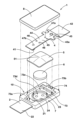
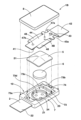
- FIG. 1 is a perspective view showing a breaker according to an embodiment of the present invention in an unassembled state
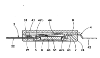
- FIG. 2 is a cross-sectional view showing the breaker in a normal charging or discharging state
- 4 is a cross-sectional view showing the breaker in an overcharged state or during an abnormality.
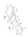
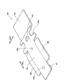
- FIG. FIG. 2 is a perspective view showing the movable piece of FIG. 1 .
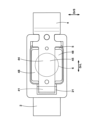
- FIG. 2 is a plan view of the breaker seen through the cover member of FIG. 1 .
- FIG. 4 is a cross-sectional view showing a breaker in a conductive state. Cross section of the breaker shown in Figure 6 along line A-A.
- FIG. 5 is a perspective view of a modified example of the movable piece of FIG. 4 .
- FIG. 2 is a perspective view of a modified example of the breaker of FIG. 1 .
- FIG. 10 is a perspective view of the movable piece of FIG. 9 .
- FIG. 10 is a plan view of the breaker seen through the cover member of FIG. 9 .
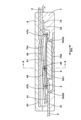
- 12 is a cross-section of the breaker of FIG. 11 .
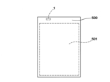
- FIG. 2 is a front view of the secondary battery pack equipped with the breaker and the like shown in FIG. 1 .
- FIG. 2 is a circuit diagram of a safety circuit including the breaker shown in FIG. 1 .
- FIG. 1 to 3 show the configuration of a breaker 1 of the present invention. Breaker 1 is mounted on electrical equipment and protects the electrical equipment from excessive temperature rise or overcurrent.
- the breaker 1 is composed of a fixed piece 2 with a fixed contact 21, a movable piece 4 with a movable contact 41 at one end, a thermally responsive element 5 that deforms with temperature changes, a PTC (Positive Temperature Coefficient) thermistor 6, and a case 10 that houses the fixed piece 2, the movable piece 4, the thermally responsive element 5, and the PTC thermistor 6.
- the case 10 is composed of a case body (first case) 7, a cover member (second case) 8 attached to the top surface of the case body 7, and other components.
- the fixed piece 2 is formed, for example, by pressing a metal plate whose main component is copper (other metal plates include copper-titanium alloy, nickel silver, brass, etc.), and is embedded in the case body 7 by insert molding.
- One end of the fixed piece 2 is formed with a terminal 22 that is electrically connected to an external circuit, and the other end is formed with a support part 23 that supports the PTC thermistor 6.
- the PTC thermistor 6 is placed on and supported by convex projections (dowels) 24 formed in three places on the support part 23 of the fixed piece 2.
- the fixed contact 21 is formed in a position opposite the movable contact 41 by cladding, plating or coating with a highly conductive material such as silver, nickel, nickel-silver alloy, copper-silver alloy, gold-silver alloy, etc., and is exposed from a part of the opening of the recess 73a formed inside the case body 7.
- the terminal 22 protrudes outward from the edge of the case body 7.
- the support part 23 is exposed from a recess 73d formed inside the case body 7.
- the surface of the fixed piece 2 on which the fixed contact 21 is formed i.e., the upper surface in FIG. 1
- the opposite surface is described as the bottom surface.
- other components such as the movable piece 4, the thermo-responsive element 5, the PTC thermistor 6, the case 10, etc.
- the movable piece 4 is formed into an arm shape that is symmetrical with respect to the center line in the longitudinal direction DrL (see Figure 4) by pressing a plate-shaped metal material whose main component is copper or the like.
- a movable contact 41 is formed at one end of the movable piece 4 in the longitudinal direction DrL.
- the movable contact 41 is formed, for example, from the same material as the fixed contact 21, and is joined to one end of the movable piece 4 by welding, cladding, crimping, or other methods.
- a terminal 42 is formed at the other end of the movable piece 4, which is electrically connected to an external circuit. Between the movable contact 41 and the terminal 42, the movable piece 4 has an abutment portion 43 (corresponding to the base end of the arm-shaped movable piece 4 and the portion embedded in the case 10) and an elastic portion 44.
- the abutment portion 43 abuts against the case body 7 and the lid member 8 between the terminal 42 and the elastic portion 44.
- the abutment portion 43 has a protruding portion 43a that protrudes like a wing in the short direction DrS (see FIG. 4) of the movable piece 4.
- DrS short direction
- the protruding portion 43a also functions effectively to position the movable piece 4 relative to the case 10 and prevent it from coming loose.
- the elastic portion 44 extends from the abutment portion 43 toward the movable contact 41.
- the movable piece 4 is supported by the case 10 in a cantilever manner at the abutment portion 43 on the base end side of the elastic portion 44, and when the elastic portion 44 elastically deforms in this state, the movable contact 41 formed at the tip of the elastic portion 44 is pressed against the fixed contact 21 and comes into contact, allowing electricity to flow between the fixed piece 2 and the movable piece 4.
- the movable piece 4 is desirably curved or bent at the elastic portion 44 by press processing.
- the movable piece 4 is curved or bent so that the tip of the elastic portion 44 is located on the bottom side of the case 10 relative to the base end.
- the thermally responsive element 5 is disposed between the movable piece 4 and the PTC thermistor 6. In other words, the thermally responsive element 5 is placed on the top surface of the PTC thermistor 6 described below.
- the thermally responsive element 5 transitions the state of the movable piece 4 from a conductive state in which the movable contact 41 is in contact with the fixed contact 21 to a cut-off state in which the movable contact 41 is separated from the fixed contact 21.
- the thermally responsive element 5 is formed into a plate shape by laminating thin plate materials with different thermal expansion coefficients, and has an initial shape with a cross section curved into an arc.
- the curved shape of the thermally responsive element 5 When the reversal operating temperature is reached due to overheating, the curved shape of the thermally responsive element 5 reverses with a snap motion, and returns to its original shape when it cools down below the forward rotation return temperature.
- the initial shape of the thermally responsive element 5 can be formed by pressing.
- the material and shape of the thermally responsive element 5 are not particularly limited, but a rectangular shape is preferable from the standpoint of productivity and efficiency of reverse warping deformation.
- the material for the thermally responsive element 5 is a laminate of two types of materials with different thermal expansion coefficients, made of various alloys such as nickel silver, brass, and stainless steel, which are used in combination according to the required conditions.
- a material for the thermally responsive element 5 that can obtain a stable reverse operating temperature and forward rotation return temperature is preferably a combination of a copper-nickel-manganese alloy on the high expansion side and an iron-nickel alloy on the low expansion side.
- a more preferable material from the standpoint of chemical stability is a combination of an iron-nickel-chromium alloy on the high expansion side and an iron-nickel alloy on the low expansion side.
- a more preferable material from the standpoint of chemical stability and workability is a combination of an iron-nickel-chromium alloy on the high expansion side and an iron-nickel-cobalt alloy on the low expansion side.
- the PTC thermistor 6 When the movable piece 4 is in an interrupted state, the PTC thermistor 6 provides electrical continuity between the fixed piece 2 and the movable piece 4 via the thermally responsive element 5.
- the PTC thermistor 6 is disposed between the fixed piece 2 and the thermally responsive element 5. In other words, the support portion 23 of the fixed piece 2 is located directly below the thermally responsive element 5, sandwiching the PTC thermistor 6.
- the type of thermistor 6 can be selected according to the needs of the operating current, operating voltage, operating temperature, return temperature, etc., and the material and shape are not particularly limited as long as these various characteristics are not impaired.
- a ceramic sintered body containing barium titanate, strontium titanate, or calcium titanate is used.
- so-called polymer PTCs which are polymers containing conductive particles such as carbon, may also be used.
- the case body 7 and the cover member 8 that constitute the case 10 are molded from thermoplastic resins such as flame-retardant polyamide, polyphenylene sulfide (PPS), liquid crystal polymer (LCP), and polybutylene terephthalate (PBT), which have excellent heat resistance.
- thermoplastic resins such as flame-retardant polyamide, polyphenylene sulfide (PPS), liquid crystal polymer (LCP), and polybutylene terephthalate (PBT), which have excellent heat resistance.
- PPS polyphenylene sulfide
- LCP liquid crystal polymer
- PBT polybutylene terephthalate
- a recess 73 is formed on the top surface of the case body 7, which is an internal space for accommodating the movable piece 4, the thermally responsive element 5, the PTC thermistor 6, etc.
- the recess 73 has recesses 73a and 73b for accommodating the movable piece 4, a recess 73c for accommodating the movable piece 4 and the thermally responsive element 5, and a recess 73d for accommodating the PTC thermistor 6.
- the edges of the movable piece 4 and the thermally responsive element 5 incorporated in the case body 7 are abutted by the frame that constitutes the recess 73, and are guided during reverse warpage deformation of the thermally responsive element 5.
- the lid member 8 is configured to cover the recess 73.
- the lid member 8 may be configured to cover at least a portion of the recess 73.
- a cover piece 81 made of a metal plate mainly composed of copper or stainless steel may be embedded in the lid member 8 by insert molding. The cover piece 81 abuts appropriately against the top surface of the movable piece 4, restricting the movement of the movable piece 4 and contributing to the miniaturization of the breaker 1 while increasing the rigidity and strength of the lid member 8 and, by extension, the case 10 as a housing.
- the cover member 8 is attached to the case body 7 so as to cover the recesses 73a, 73b, 73c, etc. of the case body 7, which contains the fixed piece 2, the movable piece 4, the thermally responsive element 5, the PTC thermistor 6, etc.
- the case body 7 and the cover member 8 are joined together by, for example, ultrasonic welding.
- Figures 2 and 3 show an overview of the operation of the breaker 1.
- Figure 2 shows the operation of the breaker 1 in a normal charging or discharging state.
- the thermally responsive element 5 maintains its initial shape before reverse bending.
- the movable contact 41 is pressed toward the fixed contact 21 by the elastic portion 44, so that the movable contact 41 and the fixed contact 21 come into contact with each other, and the fixed piece 2 and the movable piece 4 of the breaker 1 are brought into a state in which they can be electrically connected via the elastic portion 44.
- FIG 3 shows the operation of the breaker 1 in an overcharged state or during an abnormality.
- the thermally responsive element 5 which is made of laminated thin plates with different thermal expansion coefficients, deforms as the temperature rises, correcting the initial curved shape shown in Figure 2. Then, when the thermally responsive element 5 reaches its operating temperature, it snaps into an inverted shape as shown in Figure 3. This causes the thermally responsive element 5 to come into contact with the elastic part 44 of the movable piece 4, which pushes up the elastic part 44 and separates the fixed contact 21 from the movable contact 41. At this time, the current flowing between the fixed contact 21 and the movable contact 41 is cut off.
- the thermally responsive element 5 comes into contact with the movable piece 4, and a small leakage current flows through the thermally responsive element 5 and the PTC thermistor 6.
- the PTC thermistor 6 provides electrical continuity between the fixed piece 2 and the movable piece 4 via the thermally responsive element 5, which is causing the movable piece 4 to transition to an interrupted state.
- the PTC thermistor 6 continues to generate heat as long as this leakage current flows, and the resistance value increases dramatically while maintaining the thermally responsive element 5 in a reverse warped state, so that the current does not flow through the path between the fixed contact 21 and the movable contact 41, and only the small leakage current mentioned above exists (forming a self-holding circuit).
- This leakage current can be used for other functions of the safety device.
- the PTC thermistor 6 is housed in the recess 73d of the case body 7.
- the PTC thermistor 6 pushes up the elastic portion 44 of the movable piece 4, jumping out of the recess 73d, and part of the periphery of the PTC thermistor 6 rides up onto the recess 73c for housing the thermally responsive element 5. This creates the risk that the disconnection state in which the movable contact 41 is separated from the fixed contact 21 will be maintained.
- FIG. 4 shows the movable piece 4.
- the movable piece 4 has a main body 45 constituting the elastic portion 44, and a first protrusion 46 protruding from the main body 45 toward the thermally responsive element 5.
- the movable piece 4 has a first protrusion 46 in the elastic portion 44 that protrudes from the main body 45 toward the thermally responsive element 5. Therefore, even when the breaker 1 receives a large impact, the first protrusion 46 comes into contact with the thermally responsive element 5, causing the movable piece 4 to suppress the movement of the thermally responsive element 5 and press the thermally responsive element 5 toward the PTC thermistor 6. This suppresses the movement of the PTC thermistor 6 and prevents it from jumping out of the recess 73d.
- FIG. 5 is a plan view of the breaker 1 seen through the cover member 8.
- the first protrusion 46 overlaps with the PTC thermistor 6 in a plan view seen from the thickness direction of the movable piece 4. This further enhances the effect of the movable piece 4 suppressing the movement of the PTC thermistor 6 via the thermally responsive element 5.
- the first protrusion 46 is formed continuously from the main body portion 45 around its entire circumference.
- “the first protrusion 46 is formed continuously from the main body portion 45 around its entire circumference” refers to a form in which the first protrusion 46 is not separated from the main body portion 45 via a notch, slit, etc.
- the first protrusion 46 is formed continuously from the main body 45 around its entire circumference, so that when the first protrusion 46 abuts the thermally responsive element 5 and presses the thermally responsive element 5 toward the PTC thermistor 6, the amount of protrusion of the first protrusion 46 relative to the main body 45 is stable. This further suppresses the movement of the PTC thermistor 6.
- FIG. 6 shows the breaker 1 in a conductive state.
- the thermally responsive element 5 has a top 51 that protrudes towards the movable piece 4 in the conductive state. This gives the thermally responsive element 5 a curved shape that is convex towards the movable piece 4.
- Such a thermally responsive element 5 can instantly deform (so-called snap deformation) in response to a change in temperature, causing the breaker 1 to instantly transition from a conductive state to a cut-off state.
- the first protrusion 46 is preferably arranged in a region where the distance between the main body 45 and the thermally responsive element 5 is minimum in a cross section parallel to the longitudinal direction DrL of the movable piece 4. This reduces the clearance between the first protrusion 46 and the thermally responsive element 5 in the conductive state, further enhancing the effect of the movable piece 4 suppressing the movement of the PTC thermistor 6 via the thermally responsive element 5.
- the thermally responsive element 5 is formed in a curved shape, the distance between the main body 45 and the thermally responsive element 5 is often smallest at a certain point. However, in an extremely small breaker 1, it is difficult to identify the point where the above distance is smallest. In such a case, for example, the area where the above distance is 100% to 130% of the minimum value may be defined as the area where the above distance is smallest.
- the thermally responsive element 5 is usually placed on the top surface of the PTC thermistor 6 so that the center of the thermally responsive element 5 coincides with the center of the PTC thermistor 6 in the longitudinal direction DrL of the movable piece 4.
- the elastic part 44 of the movable piece 4 is curved or bent by press processing, so that when the side of the movable contact 41 is considered the front side, the elastic part 44 is configured to be inclined forward toward the tip. Therefore, the area where the distance between the main body part 45 and the thermally responsive element 5 is smallest is located forward of the center of the thermally responsive element 5 in the longitudinal direction DrL of the movable piece 4.
- FIG. 7 shows a cross section of the breaker 1 in FIG. 6 taken along line A-A.
- the cross section of line A-A passes through the first protrusion 46 and is parallel to the short-side direction DrS of the movable piece 4.
- a plurality of first protrusions 46 are arranged along the short-side direction DrS of the movable piece 4.
- a pair of first protrusions 46 are arranged parallel to the short-side direction DrS of the movable piece 4.
- the pair of first protrusions 46 are arranged symmetrically with respect to the center line of the longitudinal direction DrL of the movable piece 4. In this configuration, protrusion of the PTC thermistor 6 in the short-side direction DrS, as shown by the dashed line in FIG. 7, is suppressed.
- the number of first protrusions 46 may be three or more, and a plurality of first protrusions 46 may be arranged parallel to the longitudinal direction DrL of the movable piece 4.
- the movable piece 4 may have a pair of second protrusions 47a, 47b that protrude from the main body 45 toward the thermally responsive element 5.
- the second protrusions 47a, 47b are formed in an area that does not overlap with the PTC thermistor 6 in a plan view (see Figure 5).
- the thermally responsive element 5 is separated from the second protrusions 47a and 47b of the movable piece 4 in the conductive state. This makes it easier to maintain the contact pressure between the movable contact 41 and the fixed contact 21, stabilizing the contact resistance between the two.
- the elastic portion 44 of the movable piece 4 and the thermally responsive element 5 may be in contact.
- the movable piece 4, the thermally responsive element 5, the PTC thermistor 6, and the fixed piece 2 are conductive as a circuit.
- the resistance of the PTC thermistor 6 is overwhelmingly greater than the resistance of the movable piece 4, the current flowing through the PTC thermistor 6 is essentially negligible compared to the amount flowing through the fixed contact 21 and the movable contact 41.
- the first distance Ds1 from the first protrusion 46 to the thermally responsive element 5 is preferably smaller than the second distance Ds2a from the second protrusion 47a to the thermally responsive element 5.
- the first distance Ds1 from the first protrusion 46 to the thermally responsive element 5 is preferably smaller than the second distance Ds2b from the second protrusion 47b to the thermally responsive element 5. This reduces the clearance between the first protrusion 46 and the thermally responsive element 5 in the conductive state, further enhancing the effect of the movable piece 4 suppressing the movement of the PTC thermistor 6 via the thermally responsive element 5.
- FIG. 8 is a perspective view of a movable piece 4A, which is a modified version of the movable piece 4 in FIG. 4.
- the configuration of the movable piece 4 described above can be adopted for the parts of the movable piece 4A that are not described below.
- the first protrusion 46A has a longitudinal direction.
- the longitudinal direction of the first protrusion 46A coincides with the longitudinal direction DrL of the movable piece 4A.
- Such a first protrusion 46A also functions as a reinforcing rib that increases the elastic force of the elastic portion 44 of the movable piece 4A.
- the longitudinal direction of the first protrusion 46A may be configured to coincide with the lateral direction DrS of the movable piece 4A.
- FIG. 9 is a perspective view of a breaker 1B, which is a modified example of the breaker 1 in FIG. 1.
- the configuration of the breaker 1 described above can be adopted for the parts of the breaker 1B that are not described below.
- Breaker 1B differs from breaker 1 in that it has a movable piece 4B.
- FIG. 10 shows the movable piece 4B.
- the movable piece 4B has a wide portion 48 in the elastic portion 44.
- the wide portion 48 is a portion of the movable piece 4B whose width in the short direction DrS is wider than the PTC thermistor 6.
- the wide portion 48 is formed by extending both ends of the elastic portion 44 in the short direction DrS.
- the wide portion 48 may be extended in the short direction DrS so that the width in the short direction DrS is wider than the abutment portion 43, i.e., so that the width in the short direction DrS is maximum in the movable piece 4B.
- Figure 11 is a plan view of breaker 1B seen through cover member 8. It is desirable that wide portion 48 overlaps with PTC thermistor 6 in a plan view seen from the thickness direction of movable piece 4B. This further enhances the effect of movable piece 4B suppressing the movement of PTC thermistor 6 via thermally responsive element 5. Also, because the width of wide portion 48 in the short direction DrS is wider than that of PTC thermistor 6, the effect of movable piece 4B suppressing the movement of PTC thermistor 6 via thermally responsive element 5 is further enhanced.
- FIG. 12 shows a cross section parallel to the short direction DrS of the movable piece 4B of the breaker 1B. It is desirable that both ends of the wide portion 48 in the short direction DrS are curved or bent toward the PTC thermistor 6. Such a wide portion 48 reduces the clearance between the wide portion 48 and the thermally responsive element 5 in the conductive state, further enhancing the effect of the movable piece 4B suppressing the movement of the PTC thermistor 6 via the thermally responsive element 5.
- the wide portion 48 may be provided with a third protrusion (not shown) that protrudes toward the thermally responsive element 5.
- a third protrusion reduces the clearance between the third protrusion and the thermally responsive element 5 in the conductive state, further enhancing the effect of the movable piece 4B suppressing the movement of the PTC thermistor 6 via the thermally responsive element 5.
- the multiple third protrusions are provided.
- the multiple third protrusions are arranged along the short-side direction DrS of the movable piece 4B.
- the third protrusions are arranged on the outside of the PTC thermistor 6 in a plan view seen from the thickness direction of the movable piece 4.
- the third protrusions do not need to be arranged parallel to the short-side direction DrS of the movable piece 4B, but may be arranged diagonally across the wide portion 48. In this case, it is preferable that the third protrusions are arranged symmetrically with respect to the center of the PTC thermistor 6 in the plan view described above.
- FIG. 13 shows a secondary battery pack 500.
- the secondary battery pack 500 includes a secondary battery 501 and a breaker 1 etc. provided in the output circuit of the secondary battery 501.
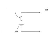
- FIG. 14 shows a safety circuit 502 for electrical equipment.
- the safety circuit 502 includes a breaker 1 etc. in series in the output circuit of the secondary battery 501.
- a part of the safety circuit 502 may be formed by a cable including a connector equipped with a breaker 1 etc.
- the breaker 1 of the present invention has been described in detail above, but the present invention is not limited to the specific embodiment described above and may be modified and implemented in various forms.
- the breaker 1 of this embodiment has a movable piece 4 with which the terminal 42 or elastic portion 44 is integrally formed, but the present invention can also be applied to a configuration in which the terminal and the movable piece are configured as separate parts (for example, the breaker described in JP 2018-005994 A).
- the movable piece has a second projection that projects from the main body toward the thermally responsive element in a region that does not overlap with the positive temperature coefficient thermistor in the plan view, 2.
- the breaker of claim 1 wherein a first distance from the first protrusion to the thermally responsive element is smaller than a second distance from the second protrusion to the thermally responsive element.
- the present invention 9 8 The breaker according to claim 7, wherein the wide portion has a third projection that protrudes toward the thermally responsive element.
- a secondary battery pack comprising a breaker according to any one of claims 1 to 9.
Landscapes
- Thermally Actuated Switches (AREA)
Applications Claiming Priority (2)
| Application Number | Priority Date | Filing Date | Title |
|---|---|---|---|
| JP2023106264A JP2025005860A (ja) | 2023-06-28 | 2023-06-28 | ブレーカー、安全回路及び2次電池パック |
| JP2023-106264 | 2023-06-28 |
Publications (1)
| Publication Number | Publication Date |
|---|---|
| WO2025005145A1 true WO2025005145A1 (ja) | 2025-01-02 |
Family
ID=93938646
Family Applications (1)
| Application Number | Title | Priority Date | Filing Date |
|---|---|---|---|
| PCT/JP2024/023206 Pending WO2025005145A1 (ja) | 2023-06-28 | 2024-06-26 | ブレーカー、安全回路及び2次電池パック |
Country Status (2)
| Country | Link |
|---|---|
| JP (1) | JP2025005860A (enExample) |
| WO (1) | WO2025005145A1 (enExample) |
Citations (3)
| Publication number | Priority date | Publication date | Assignee | Title |
|---|---|---|---|---|
| JP2005129471A (ja) * | 2003-10-27 | 2005-05-19 | Furukawa Electric Co Ltd:The | サーマルプロテクタ |
| JP2017147029A (ja) * | 2016-02-15 | 2017-08-24 | 大塚テクノ株式会社 | ブレーカとこのブレーカの製造方法、及びブレーカを備える電池パックの製造方法 |
| JP2019149285A (ja) * | 2018-02-27 | 2019-09-05 | ボーンズ株式会社 | ブレーカー及びそれを備えた安全回路 |
-
2023
- 2023-06-28 JP JP2023106264A patent/JP2025005860A/ja active Pending
-
2024
- 2024-06-26 WO PCT/JP2024/023206 patent/WO2025005145A1/ja active Pending
Patent Citations (3)
| Publication number | Priority date | Publication date | Assignee | Title |
|---|---|---|---|---|
| JP2005129471A (ja) * | 2003-10-27 | 2005-05-19 | Furukawa Electric Co Ltd:The | サーマルプロテクタ |
| JP2017147029A (ja) * | 2016-02-15 | 2017-08-24 | 大塚テクノ株式会社 | ブレーカとこのブレーカの製造方法、及びブレーカを備える電池パックの製造方法 |
| JP2019149285A (ja) * | 2018-02-27 | 2019-09-05 | ボーンズ株式会社 | ブレーカー及びそれを備えた安全回路 |
Also Published As
| Publication number | Publication date |
|---|---|
| JP2025005860A (ja) | 2025-01-17 |
Similar Documents
| Publication | Publication Date | Title |
|---|---|---|
| JP5695695B2 (ja) | ブレーカー及びそれを備えた二次電池 | |
| JP6967878B2 (ja) | ブレーカー及びそれを備えた安全回路。 | |
| JP6997689B2 (ja) | ブレーカー、安全回路及び2次電池パック | |
| JP6967932B2 (ja) | ブレーカー及びそれを備えた安全回路。 | |
| JP6979127B2 (ja) | ブレーカー、安全回路及び2次電池パック | |
| WO2020184298A1 (ja) | ブレーカーの製造方法 | |
| WO2025005145A1 (ja) | ブレーカー、安全回路及び2次電池パック | |
| JP7083742B2 (ja) | 熱応動素子、ブレーカー、安全回路及び2次電池パック | |
| JP7280848B2 (ja) | ブレーカー、安全回路及び2次電池パック | |
| JP7645783B2 (ja) | ブレーカー、安全回路及び2次電池パック | |
| JP7492495B2 (ja) | ブレーカー、安全回路及び2次電池パック | |
| EP4398281A1 (en) | Breaker, safety circuit, and secondary battery pack | |
| JP7425768B2 (ja) | ブレーカー、安全回路及び2次電池パック | |
| WO2025088885A1 (ja) | ブレーカー、電気機器用の安全回路及び2次電池パック | |
| WO2025069152A1 (ja) | ブレーカー、安全回路及び2次電池パック | |
| WO2023119887A1 (ja) | ブレーカー、安全回路及び2次電池パック | |
| WO2020095694A1 (ja) | 熱応動素子、ブレーカー、安全回路及び2次電池パック | |
| WO2022085611A1 (ja) | ブレーカー及びそれを備えた安全回路、2次電池パック | |
| JP2019075354A (ja) | 電流遮断装置、安全回路及び2次電池パック。 |
Legal Events
| Date | Code | Title | Description |
|---|---|---|---|
| 121 | Ep: the epo has been informed by wipo that ep was designated in this application |
Ref document number: 24832004 Country of ref document: EP Kind code of ref document: A1 |