WO2025005137A1 - 分析装置、分析方法、及び、プログラム - Google Patents
分析装置、分析方法、及び、プログラム Download PDFInfo
- Publication number
- WO2025005137A1 WO2025005137A1 PCT/JP2024/023176 JP2024023176W WO2025005137A1 WO 2025005137 A1 WO2025005137 A1 WO 2025005137A1 JP 2024023176 W JP2024023176 W JP 2024023176W WO 2025005137 A1 WO2025005137 A1 WO 2025005137A1
- Authority
- WO
- WIPO (PCT)
- Prior art keywords
- rays
- detector
- sample
- radiation
- analysis
- Prior art date
- Legal status (The legal status is an assumption and is not a legal conclusion. Google has not performed a legal analysis and makes no representation as to the accuracy of the status listed.)
- Ceased
Links
Images


Classifications
-
- G—PHYSICS
- G01—MEASURING; TESTING
- G01N—INVESTIGATING OR ANALYSING MATERIALS BY DETERMINING THEIR CHEMICAL OR PHYSICAL PROPERTIES
- G01N1/00—Sampling; Preparing specimens for investigation
- G01N1/02—Devices for withdrawing samples
-
- G—PHYSICS
- G01—MEASURING; TESTING
- G01N—INVESTIGATING OR ANALYSING MATERIALS BY DETERMINING THEIR CHEMICAL OR PHYSICAL PROPERTIES
- G01N23/00—Investigating or analysing materials by the use of wave or particle radiation, e.g. X-rays or neutrons, not covered by groups G01N3/00 – G01N17/00, G01N21/00 or G01N22/00
- G01N23/02—Investigating or analysing materials by the use of wave or particle radiation, e.g. X-rays or neutrons, not covered by groups G01N3/00 – G01N17/00, G01N21/00 or G01N22/00 by transmitting the radiation through the material
-
- G—PHYSICS
- G01—MEASURING; TESTING
- G01N—INVESTIGATING OR ANALYSING MATERIALS BY DETERMINING THEIR CHEMICAL OR PHYSICAL PROPERTIES
- G01N23/00—Investigating or analysing materials by the use of wave or particle radiation, e.g. X-rays or neutrons, not covered by groups G01N3/00 – G01N17/00, G01N21/00 or G01N22/00
- G01N23/22—Investigating or analysing materials by the use of wave or particle radiation, e.g. X-rays or neutrons, not covered by groups G01N3/00 – G01N17/00, G01N21/00 or G01N22/00 by measuring secondary emission from the material
- G01N23/2206—Combination of two or more measurements, at least one measurement being that of secondary emission, e.g. combination of secondary electron [SE] measurement and back-scattered electron [BSE] measurement
-
- G—PHYSICS
- G01—MEASURING; TESTING
- G01N—INVESTIGATING OR ANALYSING MATERIALS BY DETERMINING THEIR CHEMICAL OR PHYSICAL PROPERTIES
- G01N23/00—Investigating or analysing materials by the use of wave or particle radiation, e.g. X-rays or neutrons, not covered by groups G01N3/00 – G01N17/00, G01N21/00 or G01N22/00
- G01N23/22—Investigating or analysing materials by the use of wave or particle radiation, e.g. X-rays or neutrons, not covered by groups G01N3/00 – G01N17/00, G01N21/00 or G01N22/00 by measuring secondary emission from the material
- G01N23/223—Investigating or analysing materials by the use of wave or particle radiation, e.g. X-rays or neutrons, not covered by groups G01N3/00 – G01N17/00, G01N21/00 or G01N22/00 by measuring secondary emission from the material by irradiating the sample with X-rays or gamma-rays and by measuring X-ray fluorescence
Definitions
- the present invention relates to an analytical device, an analytical method, and a program for performing analysis of the amount of an analyte and analysis of the elements contained in the analyte.
- the particulate matter to be analyzed is captured on a collection filter and the mass concentration is measured, and then the collection filter is moved to shift the particulate matter capture area, and X-rays are irradiated onto the particulate matter at the new position to generate fluorescent X-rays and perform analysis of the elements contained in the particulate matter.
- the location where the mass concentration is measured and the location where elemental analysis is performed are provided separately. As a result, it is necessary to move the collection filter in order to perform both mass concentration and elemental analysis, which can reduce the efficiency of analysis of the subject to be analyzed.
- the object of the present invention is to efficiently perform analysis of the quantity of the analyte and analysis of the elements.
- An analytical device includes a radiation source, a detector, and an analysis unit.
- the radiation source irradiates a sample with radiation.
- the detector detects transmitted radiation that has passed through the sample and fluorescent X-rays generated by irradiating the sample with the radiation.
- the analysis unit performs an analysis of the amount of the sample based on the transmitted radiation detected by the detector, and performs an analysis of elements contained in the sample based on the fluorescent X-rays detected by the detector.
- the detector detects both the transmitted radiation used to analyze the amount of the sample, and the fluorescent X-rays used to analyze the elements in the sample.
- the transmitted radiation and the fluorescent X-rays are detected at the same position.
- the radiation source may have a ⁇ -ray source that irradiates the sample with ⁇ -rays.
- the transmitted radiation may be transmitted ⁇ -rays that have passed through the sample and are among the ⁇ -rays irradiated by the ⁇ -ray source. This makes it possible to perform an analysis of the amount of the sample using the transmitted ⁇ -rays that have passed through the sample.
- the radiation source may have an X-ray source that irradiates the sample with X-rays.
- the fluorescent X-rays may be generated by irradiating the sample with X-rays. This makes it possible to analyze the elements contained in the sample using the fluorescent X-rays generated by irradiating the sample with X-rays.
- the sample may be particulate matter contained in the sample gas.
- the analytical device may further include a holding member and a collection device.
- the holding member has a first surface and a second surface opposite to the first surface, and holds the sample.
- the collection device passes the sample gas through the holding member, causing the holding member to collect the particulate matter.
- the radiation source and the detector may be disposed within the collection device. This allows the analytical device to be made compact. Also, the particulate matter can be irradiated with high-intensity radiation with little attenuation, and penetrating radiation and fluorescent X-rays with little attenuation can be detected by the detector.
- the ⁇ -ray source may be disposed on the first surface side of the holding member.
- the X-ray source and detector may be disposed on the second surface side of the holding member. This allows the detector to reliably detect transmitted ⁇ -rays and fluorescent X-rays.
- the detector When the detector is used to detect transmitted ⁇ rays, the irradiation of X-rays may be stopped. This allows the detection of transmitted ⁇ rays that are not affected by fluorescent X-rays, making it possible to perform accurate analysis of the amount of sample.
- the detector may be a silicon drift detector. This allows the detector to detect penetrating radiation and fluorescent X-rays with high sensitivity.
- the fluorescent X-rays may be generated by irradiating a sample with ⁇ rays. This makes it possible to analyze the elements contained in the sample using the fluorescent X-rays generated by irradiating a sample with ⁇ rays.
- An analytical method is a method for analyzing a sample using an analytical device including a detector for detecting radiation.
- the analytical method includes the following steps. A step of irradiating the sample with radiation. A step in which a detector detects transmitted radiation that has passed through the sample and fluorescent X-rays that are generated by irradiating the sample with radiation. Performing an analysis of the amount of sample based on the transmitted radiation detected by the detector. A step of analyzing the elements contained in the sample based on the fluorescent X-rays detected by the detector.
- the detector detects both the transmitted radiation, which is used to analyze the amount of the sample, and the fluorescent X-rays, which are used to analyze the elements in the sample.
- the transmitted radiation and the fluorescent X-rays are detected at the same position.
- a program according to yet another aspect of the present invention is a program for causing a computer to execute a method for analyzing a sample using an analysis apparatus including a detector for detecting radiation.
- the analysis method includes the following steps. A step of irradiating the sample with radiation. A step in which a detector detects transmitted radiation that has passed through the sample and fluorescent X-rays that are generated by irradiating the sample with radiation. Performing an analysis of the amount of sample based on the transmitted radiation detected by the detector. A step of analyzing the elements contained in the sample based on the fluorescent X-rays detected by the detector.
- the transmitted radiation and fluorescent X-rays are detected at the same position, so there is no need to move the sample to detect both the transmitted radiation and the fluorescent X-rays, allowing the sample to be analyzed efficiently.
- FIG. 1 is a diagram showing the configuration of an analysis device according to a first embodiment.
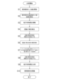
- 4 is a flowchart showing an analysis operation of particulate matter.
- FIG. 4 is a diagram showing the flow of sample gas inside a nozzle.
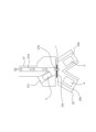
- FIG. 4 is a diagram showing the propagation path of ⁇ rays inside the nozzle and the suction part.
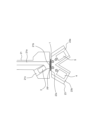
- FIG. 2 is a diagram showing the propagation paths of X-rays and fluorescent X-rays.
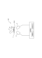
- FIG. 13 is a diagram showing the configuration of an analysis device according to a second embodiment.
- the analysis device 100 is a device capable of performing analysis of the amount of a sample held in a holding member and analysis of the elements contained in the sample.
- the analysis of the amount of a sample is performed by irradiating the sample with ⁇ -rays and based on the intensity of the ⁇ -rays that pass through the sample (called transmitted ⁇ -rays).
- the analysis of the elements contained in the sample is performed based on fluorescent X-rays generated from the sample when the sample is irradiated with X-rays.
- the transmitted ⁇ -rays and fluorescent X-rays are detected by one detector.
- the subject of analysis by the analysis device 100 is particulate matter FP contained in the sample gas Gs.
- the sample gas Gs is, for example, the atmosphere or a gas generated in various combustion processes.
- the various combustion processes include, for example, the combustion process in thermal power generation, the combustion process in a steel plant, the combustion process in an incinerator, or the combustion process of coal. In such combustion processes, for example, unburned matter in the ash, fly ash, etc. are generated as particulate matter FP.
- dust generated from various types of transportation equipment can be the particulate matter FP to be analyzed.
- dust generated by natural disasters such as volcanic eruptions (for example, volcanic ash), or dust generated during mining development can also be the particulate matter FP to be analyzed.
- the analytical device 100 detects transmitted beta rays that pass through the particulate matter FP held by the holding member, and fluorescent X-rays that are generated by irradiating the particulate matter FP held by the holding member with X-rays.
- the sample in the analytical device 100 is the particulate matter FP held by the holding member.
- Fig. 1 is a diagram showing the configuration of the analysis apparatus according to the first embodiment.
- the analysis apparatus 100 includes a holding member 1, a collection device 2, a ⁇ -ray source 3, an X-ray source 4, a detector 5, and an analysis unit 6.
- the holding member 1 has a first surface SU1 and a second surface SU2 opposite to the first surface SU1, and is a member that captures particulate matter FP contained in the sample gas Gs.
- the holding member 1 is a collection filter formed by laminating a collection layer formed of a porous fluororesin material having holes capable of capturing particulate matter FP on a reinforcing layer formed of a nonwoven fabric of a polymer material (such as polyethylene).
- a polymer material such as polyethylene
- the analysis device 100 includes a moving unit 11.
- the moving unit 11 moves the holding member 1 in the length direction.
- the moving unit 11 has a take-up reel 11a and a feed reel 11b.
- the take-up reel 11a is connected to one end of the holding member 1 in the length direction.
- the take-up reel 11a is rotatable in a predetermined direction by, for example, a motor.
- the feed reel 11b is connected to the other end of the holding member 1.
- the feed reel 11b rotates in accordance with the movement of the holding member 1.
- the holding member 1 in the moving section 11, by rotating the take-up reel 11a, the holding member 1 can be sent out from the delivery reel 11b and taken up by the take-up reel 11a. In other words, the holding member 1 can be moved in the length direction of the holding member 1 (the direction indicated by the thick arrow in Figure 1) by rotating the take-up reel 11a.
- the mechanism for moving the holding member 1 is not limited to the above mechanism.
- a pin may be provided in the width direction of the holding member 1, and the direction of movement of the holding member 1 may be changed before and after passing through the pin.
- a tension controller may be provided on the holding member 1 to adjust the tension.
- the collection device 2 collects particulate matter FP contained in the sample gas Gs in the holding member 1.
- the collection device 2 has a nozzle 21, a suction unit 23, and a suction pump 25.
- the nozzle 21 is provided at a position facing the first surface SU1 of the holding member 1.
- the nozzle 21 passes the sample gas Gs from the first surface SU1 side to the second surface SU2 side of the holding member 1, and collects the particulate matter FP contained in the sample gas Gs in the holding member 1.
- the nozzle 21 has a gas flow path 21a and an outlet opening 21b.
- the gas flow path 21a is a flow path formed inside the nozzle 21 and extending in the longitudinal direction of the nozzle 21 (the normal direction D N of the holding member 1). Since the gas flow path 21a is formed extending in the normal direction D N of the holding member 1, it is possible to prevent the particulate matter FP contained in the sample gas Gs from accumulating in the gas flow path. As a result, it is possible to increase the efficiency of collection of the particulate matter FP into the holding member 1.
- the normal direction D N is not limited to a direction that forms an angle of 90° with the first surface SU1/second surface SU2 of the holding member 1, and may be slightly deviated from 90° with the first surface SU1 of the holding member 1.
- the normal direction D N can be defined as a direction that forms an angle of 80° to 100° with the surface of the holding member 1.
- the outlet opening 21b is an opening formed at the end of the gas flow path 21a on the side where the holding member 1 is placed.
- the outlet opening 21b is provided to face the first surface SU1 of the holding member 1, and serves as an outlet for the sample gas Gs that has flowed through the gas flow path 21a.
- the end of the gas flow path 21a opposite the side where the holding member 1 is placed is connected to an inlet for the sample gas Gs.
- the analysis device 100 may also include a diluter that dilutes the sample gas Gs with a gas such as air.
- the diluter is provided, for example, between the gas flow path 21a and the inlet for the sample gas Gs.
- the sample gas Gs may contain a high concentration of particulate matter FP. By diluting the sample gas Gs, the concentration of particulate matter FP contained in the diluted sample gas Gs can be reduced. As a result, the possibility of contamination of the nozzle 21 (including the gas flow path 21a, outlet opening 21b, etc.) and/or clogging of the holding member 1 can be reduced.
- the analysis device 100 may also include a classifier that classifies the particulate matter FP contained in the sample gas Gs.
- the classifier is provided, for example, between the gas flow path 21a and the inlet for the sample gas Gs. This allows the particulate matter FP of the classified size to be collected in the holding member 1.
- the gas flow path 21a may extend in the direction of gravity inside the nozzle 21. This prevents the particulate matter FP from accumulating in the gas flow path 21a, and allows more particulate matter FP to be collected in the holding member 1, improving the analytical accuracy of the particulate matter FP.
- the nozzle 21 has a first radiation source installation space 21c.
- the first radiation source installation space 21c is a space formed at a position outside the gas flow path 21a inside the nozzle 21 and extending in a direction inclined with respect to the normal direction D -N of the holding member 1.
- a ⁇ radiation source 3 is provided in the first radiation source installation space 21c.
- the first radiation source installation space 21c merges with the gas flow path 21a at the outlet opening 21b. As a result, the gas flow path 21a and the first radiation source installation space 21c communicate with the outside space via the common outlet opening 21b.
- the nozzle 21 may be movable in a direction approaching the first surface SU1 of the holding member 1 and in a direction away from the first surface SU1.
- collection of particulate matter FP on the holding member 1 and analysis of the particulate matter FP are performed with the nozzle 21 brought close to the first surface SU1 and the holding member 1 clamped and fixed together with the suction part 23.
- movement of the holding member 1 and maintenance of the analysis device 100 e.g. replacement of the holding member 1 are performed with the nozzle 21 moved away from the first surface SU1.
- the suction unit 23 is provided on the second surface SU2 side of the holding member 1 so as to face the nozzle 21.
- the suction unit 23 is provided close to the second surface SU2 of the holding member 1.
- the suction unit 23 is provided with a detector installation space 23a, a second radiation source installation space 23b, an entrance opening 23c, and a suction opening 23d.
- a detector 5 is provided in the detector installation space 23a.
- the detector installation space 23a is provided at a position where it can detect transmitted ⁇ rays that are irradiated from the ⁇ -ray source 3 provided in the first radiation source installation space 21c and pass through the particulate matter FP held in the holding member 1, and where it can detect fluorescent X-rays generated by X-rays irradiated from the X-ray source 4 provided in the second radiation source installation space 23b to the particulate matter FP held in the holding member 1.
- the detector installation space 23a may be provided on the second surface SU2 side of the holding member 1.
- the detector installation space 23a may be provided so that a line segment connecting the vicinity of the center of the radiation receiving surface of the detector 5 provided in the detector installation space 23a and the vicinity of the center of the exit port of the ⁇ -ray source 3 passes through the collection region of the particulate matter FP.
- the detector installation space 23a may be provided in the suction unit 23 so that the detector 5 and the ⁇ -ray source 3 are arranged so that the line segment passes through the vicinity of the center of the collection region.
- the detector installation space 23a may be provided at a position facing the first radiation source installation space 21c ( ⁇ -ray source 3) across the holding member 1.
- the detector installation space 23a may be inclined with respect to the normal direction D N at an angle substantially the same as the inclination angle of the first radiation source installation space 21c in the nozzle 21. That is, the inclination angle of the detector 5 provided in the detector installation space 23a with respect to the normal direction D- N may be approximately the same as the inclination angle of the irradiation direction of the ⁇ -rays irradiated from the ⁇ -ray source 3. Note that “approximately” includes cases where the angle is slightly different but the light receiving surface of the detector 5 can receive the ⁇ -rays from the ⁇ -ray source 3, in addition to cases where the angle is completely the same or completely perpendicular.
- the second radiation source installation space 23b is provided with an X-ray source 4.
- the second radiation source installation space 23b is provided at a position where the fluorescent X-rays generated from the particulate matter FP by irradiating the particulate matter FP with X-rays irradiated from the X-ray source 4 can be detected by the detector 5 provided in the detector installation space 23a.
- the second radiation source installation space 23b may be provided on the second surface SU2 side of the holding member 1, i.e., on the same side as the side on which the detector installation space 23a is provided.
- the second radiation source installation space 23b may be inclined in the opposite direction to the inclination direction of the detector installation space 23a with respect to the normal direction D N at approximately the same angle as the inclination angle of the detector installation space 23a with respect to the normal direction D N. That is, the inclination angle of the irradiation direction of the X-rays from the X-ray source 4 provided in the second radiation source installation space 23b may be approximately the same as the inclination angle of the detector 5 provided in the detector installation space 23a with respect to the normal direction D N. In other words, the irradiation direction of the fluorescent X-rays generated from the particulate matter FP irradiated with X-rays may be approximately perpendicular to the radiation receiving surface of the detector 5 .
- the inlet opening 23c is provided to face the second surface SU2 of the holding member 1, and serves as an inlet for the sample gas Gs discharged from the nozzle 21 and passing through the holding member 1.
- the inlet opening 23c is connected to the detector installation space 23a and the second radiation source installation space 23b. In other words, the detector installation space 23a and the second radiation source installation space 23b are connected to the external space via the common inlet opening 23c.
- the suction opening 23d is an opening connected to the internal space of the suction section 23 (the detector installation space 23a, the second radiation source installation space 23b, and the entrance opening 23c).
- the suction pump 25 is connected to the suction opening 23d.
- the suction pump 25 suctions the internal space of the suction section 23 connected to the suction opening 23d.
- a suction force is generated at the inlet opening 23c of the suction section 23.
- the suction force generated at the inlet opening 23c reaches the outlet opening 21b and the gas flow path 21a connected thereto, and the sample gas Gs is sucked into the gas flow path 21a and discharged from the outlet opening 21b.
- the sample gas Gs discharged from the outlet opening 21b passes through the holding member 1 and is sucked into the internal space of the suction section 23 through the inlet opening 23c.
- the particulate matter FP contained in the sample gas Gs is collected and held by the holding member 1.
- the sample gas Gs sucked into the internal space of the suction section 23 is discharged to the outside by the suction pump 25.
- the ⁇ -ray source 3 is provided at a position where the ⁇ -rays emitted from the ⁇ -ray source 3 can be detected by the detector 5.
- the ⁇ -ray source 3 may be arranged with respect to the detector 5 so that a line segment connecting the vicinity of the center of the radiation receiving surface of the detector 5 and the vicinity of the center of the exit of the ⁇ -ray source 3 passes through the collection area of the particulate matter FP.
- the ⁇ -ray source 3 may be arranged with respect to the detector 5 so that the line segment passes through the vicinity of the center of the collection area.
- the ⁇ -ray source 3 may be provided in the first radiation source installation space 21c of the nozzle 21.
- the ⁇ -ray source 3 may be provided on the first surface SU1 side of the holding member 1.
- the ⁇ -ray source 3 may be provided at a position facing the detector 5 across the holding member 1.
- the ⁇ -ray source 3 may be inclined with respect to the normal direction D N of the holding member 1.
- the inclination angle of the ⁇ -ray source 3 with respect to the normal direction D N may be approximately the same as the inclination angle of the detector 5 with respect to the normal direction D N.
- the ⁇ -ray source 3 outputs ⁇ -rays to be irradiated onto the particulate matter FP captured in the holding member 1 from the first surface SU1 side of the holding member 1.
- the ⁇ -ray source 3 is a radiation source that generates ⁇ -rays such as carbon-14 ( 14 C), strontium-90 ( 90 Sr), and promethium-147 ( 147 Pm). By using these as the ⁇ -ray source, the generation of unnecessary radiation such as ⁇ -rays can be suppressed.
- the analysis device 100 calculates information about the amount of particulate matter FP captured by the holding member 1 based on the intensity of the ⁇ -rays (called transmitted ⁇ -rays) that pass through the particulate matter FP and exit from the second surface SU2.
- the information about the amount of particulate matter FP is, for example, the mass concentration of the particulate matter FP.
- the "mass concentration of particulate matter FP" is defined as the mass of particulate matter contained in the total volume of collected gas, expressed as a value per unit volume of collected gas, and can be expressed in units of, for example, ⁇ g/ m3 .
- the ⁇ -ray source 3 By providing the ⁇ -ray source 3 in the first radiation source installation space 21c, the ⁇ -ray source 3 can be disposed at an angle with respect to the normal direction D N of the holding member 1. As a result, the ⁇ -ray source 3 is prevented from interfering with the flow of the sample gas Gs in the gas flow passage 21a, and the particulate matter FP can be collected evenly and uniformly on the holding member 1.
- the ⁇ radiation source 3 can be installed inside the nozzle 21, so that ⁇ rays can be output from a position close to the first surface SU1 of the holding member 1.
- ⁇ rays with high intensity and little attenuation can be irradiated onto the particulate matter FP captured in the holding member 1.
- the gas flow path 21a of the nozzle 21 and the first radiation source installation space 21c are connected to the external space via the common outlet opening 21b. This allows the sample gas Gs flowing through the gas flow path 21a and the ⁇ -rays output from the ⁇ -ray source 3 provided in the first radiation source installation space 21c to be emitted from the common outlet opening 21b toward the holding member 1. As a result, the collection area of the particulate matter FP and the irradiation area of the ⁇ -rays can be made to coincide.
- the X-ray source 4 is provided at a position where the fluorescent X-rays generated from the particulate matter FP by the X-rays irradiated from the X-ray source 4 can be detected by the detector 5.
- the X-ray source 4 may be provided in the second radiation source installation space 23b of the suction unit 23. That is, the X-ray source 4 may be provided on the second surface SU2 side of the holding member 1.
- the X-ray source 4 may be inclined with respect to the normal direction D N.
- the X-ray source 4 may be disposed in a direction opposite to the inclination direction of the detector 5 with respect to the normal direction D N.
- the X-ray source 4 is inclined in a direction opposite to the inclination direction of the detector 5 with respect to the normal direction D N at an angle substantially equal to the inclination angle of the detector 5 with respect to the normal direction D N. That is, the inclination angle of the irradiation direction of the X-rays from the X-ray source 4 may be substantially equal to the inclination angle of the detector 5 with respect to the normal direction D N. In other words, the irradiation direction of the fluorescent X-rays generated from the particulate matter FP may be substantially perpendicular to the radiation receiving surface of the detector 5.
- the X-ray source 4 irradiates X-rays onto the particulate matter FP collected in the holding member 1 from the second surface SU2 side of the holding member 1.
- the X-ray source 4 is, for example, a device that generates X-rays by irradiating a metal such as palladium with an electron beam.
- the analysis device 100 can perform an analysis of the elements contained in the holding member 1 (i.e., elemental analysis) based on the fluorescent X-rays generated from the particulate matter FP irradiated with X-rays.
- the irradiation state of the X-rays on the analysis target can be switched between an irradiation ON state (a state in which X-rays are irradiated) in which X-rays from the X-ray source 4 are irradiated on the analysis target, and an irradiation OFF state (a state in which X-ray irradiation is stopped) in which X-rays from the X-ray source 4 are not irradiated on the analysis target.
- the analysis unit 6 can control the X-ray source 4 to be in an ON state in which X-rays are generated, thereby setting the irradiation state to the irradiation ON state, and the X-ray source 4 to an OFF state in which X-ray generation is stopped, thereby setting the irradiation state to the irradiation OFF state.
- a shutter may be provided at the X-ray irradiation port (second radiation source installation space 23b), and the irradiation ON state and the irradiation OFF state may be switched by opening and closing this shutter.
- the detector 5 allows the detector 5 to switch between a state in which only transmitted ⁇ rays are detected and a state in which fluorescent X-rays (and transmitted ⁇ rays) generated by irradiating X-rays on the particulate matter FP are detected.
- the detector 5 is provided at a position where it can detect beta rays irradiated from the beta radiation source 3 provided in the first radiation source installation space 21c and passing through the particulate matter FP held in the holding member 1, and where it can detect fluorescent X-rays generated by X-rays irradiated from the X-ray source 4 provided in the second radiation source installation space 23b to the particulate matter FP held in the holding member 1.
- the detector 5 may be disposed with respect to the ⁇ -ray source 3 such that a line segment connecting the vicinity of the center of the radiation receiving surface of the detector 5 and the vicinity of the center of the exit of the ⁇ -ray source 3 passes through the collection area of the particulate matter FP. More preferably, the detector 5 may be disposed with respect to the ⁇ -ray source 3 such that the line segment passes through the vicinity of the center of the collection area.
- the detector 5 may be provided in the detector installation space 23a of the suction unit 23. That is, the detector 5 may be provided on the second surface SU2 side of the holding member 1, similar to the X-ray source 4. Preferably, the detector 5 may be provided at a position facing the ⁇ -ray source 3.
- the detector 5 may be inclined with respect to the normal direction D N at an angle substantially equal to the inclination angle of the ⁇ -ray source 3. That is, the inclination angle of the detector 5 with respect to the normal direction D N may be substantially equal to the inclination angle of the irradiation direction of the ⁇ -ray irradiated from the ⁇ -ray source 3. This allows the detector 5 to detect transmitted ⁇ -rays generated when the ⁇ -rays output from the ⁇ -ray source 3 pass through the particulate matter FP.
- the detector 5 is provided at a position where it can detect fluorescent X-rays generated from the particulate matter FP by X-rays irradiated from the X-ray source 4.
- the detector 5 may be inclined in the opposite direction to the X-ray source 4 with respect to the normal direction D N at approximately the same angle as the inclination angle of the X-ray source 4 with respect to the normal direction D N. That is, the inclination angle of the irradiation direction of X-rays from the X-ray source 4 with respect to the normal direction D N may be approximately the same as the inclination angle of the detector 5 with respect to the normal direction D N.
- the radiation receiving surface of the detector 5 may be approximately perpendicular to the irradiation direction of the fluorescent X-rays generated from the particulate matter FP. This allows the detector 5 to detect fluorescent X-rays generated by irradiating the particulate matter FP with X-rays by the X-ray source 4.
- the detector 5 can detect both transmitted ⁇ rays generated when ⁇ rays from the ⁇ -ray source 3 pass through the particulate matter FP, and fluorescent X-rays generated from the particulate matter FP when irradiated with X-rays from the X-ray source 4.
- transmitted ⁇ rays and fluorescent X-rays can be detected in one location.
- a silicon drift detector is used as detector 5. Due to its configuration, a silicon drift detector can detect radiation with high sensitivity. Therefore, by using a silicon drift detector as detector 5, transmitted beta rays and fluorescent X-rays can be detected with high sensitivity.
- the ⁇ -ray source 3 is disposed in the nozzle 21, and the X-ray source 4 and detector 5 are disposed in the suction section 23. That is, the ⁇ -ray source 3, X-ray source 4, and detector 5 are disposed in the collection device 2.
- This allows the analysis device 100 to be made compact.
- ⁇ -rays and X-rays can be irradiated from the vicinity of the holding member 1, and transmitted ⁇ -rays and fluorescent X-rays can be detected in the vicinity of the holding member 1.
- the particulate matter FP can be irradiated with strong ⁇ -rays and X-rays with little attenuation, and transmitted ⁇ -rays and fluorescent X-rays with little attenuation can be detected by the detector 5.
- the analysis unit 6 is a computer system having a calculation unit such as a CPU, storage devices such as RAM, ROM, HDD, SSD, various interfaces, a display, etc.
- the analysis unit 6 controls each component of the analysis device 100 and performs various information processing related to the analysis device 100.
- the analysis unit 6 has a calculation unit 61.
- the calculation unit 61 is composed of the CPU, storage device, and various interfaces of the analysis unit 6, and controls each component of the analysis device 100 and performs various information processing related to the analysis device 100.
- the calculation unit 61 stores the control of each component of the analysis device 100 and various information processing related to the analysis device 100 in the storage device of the computer system that constitutes the analysis unit 6, and realizes it by software that can be executed by the analysis unit 6.
- the calculation unit 61 may realize some of the above control and information processing by hardware.
- the calculation unit 61 switches between an irradiation ON state in which X-rays are irradiated to the analysis target, and an irradiation OFF state in which X-rays are not irradiated to the analysis target.
- the calculation unit 61 can switch between the irradiation ON state and the irradiation OFF state by switching the X-ray source 4 between the ON state and the OFF state.
- the calculation unit 61 may switch between the irradiation ON state and the irradiation OFF state by switching the opening and closing of a shutter provided in the X-ray irradiation port (second source installation space 23b).
- the analysis unit 6 may have a display unit 63.
- the display unit 63 is a display that displays various information related to the analysis device 100 and the analysis results of the particulate matter FP (information related to mass concentration, information related to elements).
- the display unit 63 is, for example, a liquid crystal display, an organic EL display, or the like.
- the analysis results and the like may be stored in a storage device of the analysis unit 6, for example.
- the analysis results and the like stored in the storage device may be capable of being transmitted to a terminal or the like connected to the analysis unit 6.
- the analysis results and the like may be displayed on a display device of a terminal or the like connected to the analysis unit 6.
- the analytical device 100 may include a main body B.
- the main body B is a housing that houses the analytical device 100.
- the main body B and each component of the analytical device 100 may generate radiation due to interaction with the radiation generated from the ⁇ -ray source 3 and the X-ray source 4, but it is preferable to minimize the effect of this radiation on the analysis results of the particulate matter FP.
- the main body B and each component of the analytical device 100 are preferably made of a material that generates radiation (such as fluorescent X-rays) with an energy different from the energy of fluorescent X-rays generated from the particulate matter FP irradiated with X-rays.
- FIG. 2 is a flow chart showing the analyzing operation of the particulate matter.
- ⁇ -rays are irradiated from the ⁇ -ray source 3 toward the holding member 1 on which the particulate matter FP is not collected (step S1).
- the detector 5 detects the ⁇ -rays irradiated from the ⁇ -ray source 3 and passing through the holding member 1.
- the calculation unit 61 regards the detection signal of the ⁇ -rays that have passed through the holding member 1 on which the particulate matter FP is not collected, input from the detector 5, as data on the intensity of the ⁇ -rays.
- the sample gas Gs is caused to flow in the normal direction D N of the holding member 1 to cause the particulate matter FP contained in the sample gas Gs to be collected by the holding member 1 (step S3). Note that even during the collection of the particulate matter FP, ⁇ rays continue to be output from the ⁇ -ray source 3. Specifically, the particulate matter FP is collected by the holding member 1 as follows.
- the calculation unit 61 operates the suction pump 25 to generate a suction force at the inlet opening 23c of the suction unit 23. Since the inlet opening 23c faces the outlet opening 21b of the nozzle 21, the suction force generated at the inlet opening 23c extends to the outlet opening 21b and the gas flow path 21a connected thereto. As a result, as shown in FIG. 3, the sample gas Gs is sucked into the gas flow path 21a from the intake port. The sample gas Gs sucked into the gas flow path 21a flows through the gas flow path 21a toward the holding member 1 and is discharged from the outlet opening 21b. The sample gas Gs discharged from the outlet opening 21b passes through the holding member 1.
- the gas flow path 21a through which the sample gas Gs flows is parallel to the normal direction D N of the holding member 1, while the ⁇ -ray source 3 is provided at an angle to the normal direction D N.
- the ⁇ -ray source 3 does not overlap with the gas flow path 21a, and therefore does not interfere with the flow of the sample gas Gs. Since the ⁇ -ray source 3 does not interfere with the flow of the sample gas Gs, the particulate matter FP can be collected evenly and uniformly on the holding member 1.
- the beta rays output from the beta ray source 3 travel in the extension direction of the first radiation source installation space 21c, and then reach the exit opening 21b.
- the beta rays that reach the exit opening 21b exit from the exit opening 21b and are irradiated to the holding member 1.
- the beta rays irradiated to the holding member 1 are partially absorbed by the particulate matter FP captured by the holding member 1 and the holding member 1, and then pass through, and are detected by the detector 5.
- Figure 4 is a diagram showing the propagation path of the beta rays inside the nozzle and suction section.
- the detector 5 After a predetermined time (e.g., 1 hour) has elapsed since the particulate matter FP was captured in the holding member 1 or since collection began, the detector 5 detects the transmitted beta rays that have been irradiated from the beta ray source 3 and passed through the particulate matter FP and the holding member 1 (step S4).
- the calculation unit 61 regards the detection signal of the transmitted beta rays input from the detector 5 as data relating to the transmitted beta rays.
- the calculation unit 61 sets the X-ray irradiation state to an irradiation OFF state in which X-rays from the X-ray source 4 are not irradiated to the particulate matter FP.
- the detector 5 detects both transmitted ⁇ rays and fluorescent X-rays at the same time.
- the signal output from detector 5 contains both a signal due to the detection of transmitted ⁇ rays and a signal due to the detection of fluorescent X-rays. It is difficult to separate the signal due to the detection of transmitted ⁇ rays and the signal due to the detection of fluorescent X-rays from the signal output from detector 5.
- the detector 5 can detect transmitted ⁇ rays that are not affected by fluorescent X-rays, allowing accurate analysis of the amount of particulate matter FP.
- the calculation unit 61 sets the X-ray irradiation state to an irradiation ON state in which the particulate matter FP is irradiated with X-rays from the X-ray source 4 (step S5).
- the X-rays output from the X-ray source 4 proceed in the extension direction of the second radiation source installation space 23b, and then reach the entrance opening 23c.
- the X-rays that reach the entrance opening 23c exit the entrance opening 23c and are irradiated to the holding member 1.
- the X-rays irradiated to the holding member 1 are irradiated to the particulate matter FP captured by the holding member 1.
- FIG. 5 is a diagram showing the propagation paths of X-rays and fluorescent X-rays.
- the detector 5 detects the transmitted ⁇ rays that have passed through the particulate matter FP and the holding member 1, and the fluorescent X-rays from the particulate matter FP (step S6).
- the calculation unit 61 inputs a detection signal from the detector 5 that has detected the transmitted ⁇ rays and the fluorescent X-rays.
- the calculation unit 61 subtracts the detection signal of transmitted ⁇ rays obtained in step S4 above (the detection signal when the X-ray irradiation state is set to the irradiation OFF state) from the detection signal input from the detector 5, and regards this detection signal as the detection signal generated by the detector 5 detecting the fluorescent X-rays, and regards this as data related to the fluorescent X-rays (step S7).
- step S7 accurate data related to the fluorescent X-rays can be obtained by subtracting the detection signal obtained in step S4 (i.e., the detection signal of transmitted ⁇ rays) from the detection signal obtained in step S6 to calculate the detection signal generated by detecting the fluorescent X-rays.
- the X-ray irradiation state is set to an OFF state in which X-rays from the X-ray source 4 are not irradiated onto the particulate matter FP (step S8).
- the calculation unit 61 then analyzes the particulate matter FP based on the data on the transmitted ⁇ rays and the data on the fluorescent X-rays (step S9).
- the analysis performed in step S9 includes an analysis of the amount of particulate matter FP based on transmitted beta rays, and an analysis of the elements contained in the particulate matter FP based on fluorescent X-rays.
- the calculation unit 61 performs an analysis of the amount of particulate matter FP captured in the holding member 1 based on the data on the transmitted beta rays. Specifically, the calculation unit 61 calculates the mass concentration of particulate matter FP contained in the sample gas Gs based on the ratio between the intensity of the beta rays that have passed through the holding member 1 where no particulate matter FP has been captured, i.e., the intensity of the beta rays obtained by performing steps S1 to S2 above, and the intensity of the transmitted beta rays that have passed through the particulate matter FP (and the holding member 1), i.e., the intensity of the transmitted beta rays included in the data on the transmitted beta rays obtained by performing step S4 above.
- the calculation unit 61 also performs an analysis of the elements contained in the particulate matter FP captured in the holding member 1 based on the data on the fluorescent X-rays obtained in step S7 above. Specifically, the calculation unit 61 can identify the elements contained in the particulate matter FP from the energy value of the fluorescent X-rays contained in the data on the fluorescent X-rays, and can calculate the content of the elements from the intensity of the fluorescent X-rays.
- the calculation unit 61 rotates the take-up reel 11a to move the holding member 1 (step S10).
- the particulate matter FP that has been analyzed is moved to a position outside the collection device 2. Instead, the holding member 1 on which no particulate matter FP has been collected is placed in the collection device 2. If further analysis is to be performed, the above steps S1 to S9 are newly executed.
- one detector 5 detects both the transmitted ⁇ rays used to analyze the amount of particulate matter FP and the fluorescent X-rays used to analyze the elements contained in the particulate matter FP.
- the transmitted ⁇ rays and the fluorescent X-rays are detected at the same position.
- the analysis device 100 there is no need to move the particulate matter FP collection area of the holding member 1 to detect both the transmitted ⁇ rays and the fluorescent X-rays, so the particulate matter FP can be analyzed efficiently.
- the holding member 1 since the holding member 1 does not move, the irradiation position of the ⁇ rays and X-rays on the holding member 1 (particulate matter FP) does not shift, and analysis can be performed in a short time.
- the particulate matter FP can be collected without any gaps in the length direction of the holding member 1, waste of the holding member 1 can be reduced.
- the cost of the analysis device 100 can be reduced.
- the trapping device 2 is provided to trap particulate matter FP in the atmosphere in the holding member 1.
- the present invention is not limited to this, and the analysis device 100' according to the second embodiment may not include the trapping device 2, as shown in Fig. 6.
- Fig. 6 is a diagram showing the configuration of the analysis device according to the second embodiment.
- the detector 5 is also provided at a position where it can detect transmitted ⁇ -rays irradiated from the ⁇ -ray source 3 and passing through the measurement object, and where it can detect fluorescent X-rays generated by X-rays irradiated from the X-ray source 4 to the measurement object.
- the ⁇ -ray source 3 and the detector 5 may be arranged so that a line segment connecting the vicinity of the center of the radiation receiving surface of the detector 5 and the vicinity of the center of the exit of the ⁇ -ray source 3 passes through the collection area of the particulate matter FP.
- the detector and the ⁇ -ray source may be arranged so that the line segment passes through the vicinity of the center of the collection area.
- the inclination angle of the detector 5 with respect to the normal direction D N may be approximately the same as the inclination angle of the irradiation direction of the ⁇ -rays irradiated from the ⁇ -ray source 3 with respect to the normal direction D N.
- the detector 5 may be inclined in the opposite direction to the X-ray source 4 with respect to the normal direction D N at approximately the same angle as the inclination angle of the X-ray source 4 with respect to the normal direction D N.
- the radiation receiving surface of the detector 5 may be substantially perpendicular to the irradiation direction of the fluorescent X-rays generated from the particulate matter FP.
- This analysis device 100' can be used, for example, when it is not necessary to collect particulate matter FP on the holding member 1. Even if it is necessary to collect particulate matter FP on the holding member 1, for example, particulate matter FP collected on the holding member 1 at another location can be analyzed by the analysis device 100'.
- the holding member 1 does not have to be a collection filter.
- a plate-shaped member on which the measurement target (e.g., particulate matter FP) is placed in advance can be provided at a position where the irradiation area of the ⁇ rays from the ⁇ ray source 3 and the irradiation area of the X-rays from the X-ray source 4 overlap.
- the X-ray irradiation state may be set to the irradiation ON state to generate fluorescent X-rays from the particulate matter FP, and after performing an analysis of the elements contained in the particulate matter FP, an analysis of the amount of particulate matter FP may be performed based on the transmitted ⁇ rays (with the X-ray irradiation state set to the irradiation OFF state).
- the analysis may be performed, for example, as follows. First, the X-ray irradiation state is set to the irradiation OFF state, transmitted ⁇ rays are detected, and an analysis of the amount of particulate matter FP is performed based on the detected transmitted ⁇ rays. Next, the X-ray irradiation state is set to the irradiation ON state, and X-rays are irradiated onto the particulate matter FP to generate fluorescent X-rays from the particulate matter FP, and the transmitted ⁇ rays and fluorescent X-rays are detected by detector 5.
- the detection signal of the transmitted ⁇ rays obtained just before the X-ray irradiation state is set to the irradiation ON state (i.e., when the irradiation is OFF) is subtracted from the detection signal obtained by detecting the transmitted ⁇ rays and fluorescent X-rays to calculate the detection signal obtained by detecting the fluorescent X-rays, and this is used as data related to the fluorescent X-rays.
- Analysis of the elements contained in the particulate matter FP may be performed based on the data related to the fluorescent X-rays obtained in this manner.
- Analysis of the amount of particulate matter FP can be performed at any time after the transmitted ⁇ rays are detected by detector 5. Furthermore, analysis of the elements contained in the particulate matter FP can be performed at any time after the fluorescent X-rays are detected by detector 5.
- Other devices may be controlled based on the analysis results output by the analysis unit 6 of the above-mentioned analysis device 100. For example, when the particulate matter FP generated in a waste incineration facility is the subject of analysis, the analysis result may be output as to whether or not the particulate matter FP contains harmful substances, and when this analysis result is output, a specific device in the waste incineration facility may be operated.
- the above-mentioned analytical device 100 can be combined with another analytical device (e.g., a gas analyzer) to construct a system for performing more detailed analysis of the subject of analysis.
- another analytical device e.g., a gas analyzer
- the configuration of the collection device 2 is not limited to the configuration described in the first embodiment.
- the collection device 2 only needs to have a configuration that allows the particulate matter FP to be measured to be collected in the holding member 1.
- the sample gas Gs is caused to pass through the collection surface of the holding member 1 by suction with the suction unit 23.
- the particulate matter FP may be collected in the holding member 1 by forcing the sample gas Gs into the first surface SU1 (i.e., spraying the sample gas Gs onto the first surface SU1 at a predetermined pressure).
- the suction unit 23 may be omitted, and the X-ray source 4 and detector 5 may be disposed in the external space.
- the ⁇ -ray source 3 is provided in the first radiation source installation space 21c inside the nozzle 21, but this is not limited thereto.
- the ⁇ -ray source 3 may be provided outside the nozzle 21 at a position inclined with respect to the normal direction D- N of the collection surface.
- the X-ray source 4 and/or the detector 5 may be disposed in the external space instead of being provided inside the suction unit 23.
- the ⁇ -ray source 3 may be arranged parallel to the normal direction D- N within the gas flow path 21a of the nozzle 21, and the detector 5 may be arranged directly below the ⁇ -ray source 3 in the suction section 23 (i.e., on the line connecting the ⁇ -ray source 3 and the collection area of the holding member 1) and parallel to the normal direction D- N , and only the X-ray source 4 may be tilted with respect to the normal direction D- N and arranged at a position off the line connecting the ⁇ -ray source 3 and the collection area of the holding member 1.
- a shutter that blocks the beta rays output from the beta ray source 3 may be provided near the beta ray source 3.
- the shutter may be used to prevent the beta rays from being irradiated to the particulate matter FP during analysis using fluorescent X-rays.
- the irradiation of beta rays from the beta ray source 3 may be controlled to start and stop by the control of the calculation unit 61. This makes it possible to prevent the detector 5 from detecting a detection signal that includes both a detection signal resulting from the detection of transmitted beta rays and a detection signal resulting from the detection of fluorescent X-rays when detecting fluorescent X-rays from the particulate matter FP. In other words, only fluorescent X-rays are detected by the detector 5, and only a detection signal resulting from the detection of fluorescent X-rays can be obtained from the detector 5.
- the ⁇ -ray source 3, X-ray source 4, and detector 5 may be disposed externally as described in the second embodiment, and the collection device 2 may be disposed at a position different from the positions where the ⁇ -ray source 3, X-ray source 4, and detector 5 are disposed.
- the ⁇ -ray source 3 may be arranged on the second surface SU2 side of the holding member 1, and the X-ray source 4 and detector 5 may be arranged on the first surface SU1 side of the holding member 1.
- the measurement target does not have to be held by the holding member 1.
- the measurement target can also be analyzed by introducing a gas (e.g., air, exhaust gas, etc.) containing the measurement target (particulate matter FP) into a region where the irradiation region of ⁇ rays from the ⁇ -ray source 3 and the irradiation region of X-rays from the X-ray source 4 overlap, and detecting the transmitted ⁇ rays that pass through the region and the fluorescent X-rays generated from the region by the detector 5.
- a gas e.g., air, exhaust gas, etc.
- (L) Irradiation of particulate matter FP with X-rays may be started and stopped, for example, by opening and closing a shielding member provided at the X-ray outlet of second radiation source installation space 23b.
- (M) Analysis of elements contained in the particulate matter FP may be performed using fluorescent X-rays (referred to as ⁇ -ray-derived fluorescent X-rays) generated by irradiating the particulate matter FP with ⁇ -rays from the ⁇ -ray source 3, without irradiating the particulate matter FP with X-rays from the X-ray source 4.
- fluorescent X-rays referred to as ⁇ -ray-derived fluorescent X-rays
- step S8 of the analysis operation shown in FIG. 2 an analysis of the elements contained in the particulate matter FP is performed based on the ⁇ -ray-derived fluorescent X-rays detected by the detector 5.
- the analysis of the elements contained in the particulate matter FP may be performed based only on the ⁇ -ray-derived fluorescent X-rays, or the analysis of the elements contained in the particulate matter FP may be performed taking into account the fluorescent X-rays generated by irradiating the particulate matter FP with the X-rays obtained by executing steps S5 to S6.
- the X-ray source 4 can be omitted.
- An analysis device (e.g., analysis device 100) includes a radiation source, a detector (e.g., detector 5), and an analysis unit (e.g., analysis unit 6).
- the radiation source irradiates a sample (e.g., particulate matter FP) with radiation.
- the detector detects transmitted radiation that has passed through the sample, and fluorescent X-rays generated by irradiating the sample with the radiation.
- the analysis unit performs an analysis of the amount of the sample based on the transmitted radiation detected by the detector, and performs an analysis of the elements contained in the sample based on the fluorescent X-rays detected by the detector.
- the detector detects both the transmitted radiation used to analyze the amount of the sample, and the fluorescent X-rays used to analyze the elements in the sample.
- the transmitted radiation and the fluorescent X-rays are detected at the same position.
- the radiation source may have a ⁇ -ray source (e.g., ⁇ -ray source 3) that irradiates the sample with ⁇ -rays.
- the transmitted radiation may be transmitted ⁇ -rays that have penetrated the sample among the ⁇ -rays irradiated by the ⁇ -ray source. This makes it possible to perform an analysis of the amount of the sample using the transmitted ⁇ -rays that have penetrated the sample.
- the radiation source may have an X-ray source (e.g., X-ray source 4) that irradiates the sample with X-rays.
- the fluorescent X-rays may be generated by irradiating the sample with X-rays. This makes it possible to analyze the elements contained in the sample using the fluorescent X-rays generated by irradiating the sample with X-rays.
- the sample may be particulate matter (e.g., particulate matter FP) contained in a sample gas (e.g., sample gas Gs).
- the analytical device may further include a holding member (e.g., holding member 1) and a collection device (e.g., collection device 2).
- the holding member has a first surface (e.g., first surface SU1) and a second surface (e.g., second surface SU2) opposite to the first surface, and holds the sample.
- the collection device passes the sample gas through the holding member, causing the holding member to collect the particulate matter.
- the radiation source and the detector may also be disposed within the collection device. This allows the analytical device to be made compact.
- the particulate matter can be irradiated with high-intensity radiation with little attenuation, and the detector can detect penetrating radiation and fluorescent X-rays with little attenuation.
- the ⁇ -ray source may be disposed on the first surface side of the holding member.
- the X-ray source and the detector may be disposed on the second surface side of the holding member. This allows the detector to reliably detect transmitted ⁇ -rays and fluorescent X-rays.
- the irradiation of X-rays may be switched on and off.
- the detector detects transmitted ⁇ -rays
- the irradiation of X-rays may be stopped. This allows the detection of transmitted ⁇ -rays that are not affected by fluorescent X-rays, making it possible to perform accurate analysis of the amount of sample.
- the detector may be a silicon drift detector. This allows the detector to detect penetrating radiation and fluorescent X-rays with high sensitivity.
- the fluorescent X-rays may be generated by irradiating a sample with ⁇ rays. This makes it possible to analyze the elements contained in the sample using the fluorescent X-rays generated by irradiating a sample with ⁇ rays.
- the analysis method is a method for analyzing a sample using an analysis device (e.g., analysis device 100) that includes a detector (e.g., detector 5) that detects radiation.
- the analysis method includes the following steps. A step of irradiating the sample with radiation (eg, steps S3 to S4). A step of detecting, by a detector, transmitted radiation that has passed through the sample and fluorescent X-rays that are generated by irradiating the sample with radiation (for example, steps S4 to S7). A step of performing an analysis of the amount of sample based on the transmitted radiation detected by the detector (eg, step S9). A step of analyzing elements contained in the sample based on the fluorescent X-rays detected by the detector (for example, step S9).
- the detector detects both the transmitted radiation, which is used to analyze the amount of the sample, and the fluorescent X-rays, which are used to analyze the elements in the sample.
- the transmitted radiation and the fluorescent X-rays are detected at the same position.
- the program causes a computer to execute a method for analyzing a sample using an analytical device including a detector for detecting radiation.
- the method includes the following steps: A step of irradiating the sample with radiation. A step in which a detector detects transmitted radiation that has passed through the sample and fluorescent X-rays that are generated by irradiating the sample with radiation. Performing an analysis of the amount of sample based on the transmitted radiation detected by the detector. A step of analyzing the elements contained in the sample based on the fluorescent X-rays detected by the detector.
- the present invention can be widely applied to analytical devices that analyze samples.
Landscapes
- Physics & Mathematics (AREA)
- Health & Medical Sciences (AREA)
- Life Sciences & Earth Sciences (AREA)
- Chemical & Material Sciences (AREA)
- Analytical Chemistry (AREA)
- Biochemistry (AREA)
- General Health & Medical Sciences (AREA)
- General Physics & Mathematics (AREA)
- Immunology (AREA)
- Pathology (AREA)
- Analysing Materials By The Use Of Radiation (AREA)
Abstract
分析対象の量に関する分析と元素に関する分析とを効率よく行う。分析装置(100)は、放射線源と、検出器(5)と、分析部(6)と、を備える。放射線源は、粒子状物質(FP)に放射線を照射する。検出器(5)は、粒子状物質(FP)を通過する透過放射線と、粒子状物質(FP)に放射線を照射することで生じる蛍光X線と、を検出する。分析部(6)は、検出器(5)により検出された透過放射線に基づいて、粒子状物質(FP)の量に関する分析を行い、検出器(5)により検出された蛍光X線に基づいて、粒子状物質(FP)に含まれる元素に関する分析を行う。
Description
本発明は、分析対象の量に関する分析と分析対象に含まれる元素に関する分析を行う分析装置、分析方法、及びプログラムに関する。
分析対象の分析を行う装置として、分析対象を通過したβ線量に基づいて分析対象の量に関する分析(例えば、質量濃度の測定)を実行し、分析対象にX線を照射した際に発生する蛍光X線に基づいて分析対象に含まれる元素に関する分析を実行することが可能な装置が知られている(例えば、特許文献1)。
上記の装置では、分析対象である粒子状物質を捕集フィルタに捕集して質量濃度を測定し、その後、捕集フィルタを移動させて粒子状物質の捕集領域を移動させ、移動後の位置で粒子状物質にX線を照射して蛍光X線を発生させて粒子状物質に含まれる元素に関する分析を行っていた。つまり、従来の装置では、質量濃度を測定する箇所と、元素に関する分析を行う箇所とが個別に設けられている。このため、質量濃度と元素の分析を両方行うために捕集フィルタの移動が必要となり、分析対象の分析効率が低下する可能性があった。
本発明の目的は、分析対象の量に関する分析と元素に関する分析とを効率よく行うことにある。
以下に、課題を解決するための手段として複数の態様を説明する。これら態様は、必要に応じて任意に組み合せることができる。
本発明の一見地に係る分析装置は、放射線源と、検出器と、分析部と、を備える。放射線源は、試料に放射線を照射する。検出器は、放射線のうち試料を通過した透過放射線と、試料に放射線を照射することで生じる蛍光X線と、を検出する。分析部は、検出器により検出された透過放射線に基づいて試料の量に関する分析を行い、検出器により検出された蛍光X線に基づいて試料に含まれる元素に関する分析を行う。
本発明の一見地に係る分析装置は、放射線源と、検出器と、分析部と、を備える。放射線源は、試料に放射線を照射する。検出器は、放射線のうち試料を通過した透過放射線と、試料に放射線を照射することで生じる蛍光X線と、を検出する。分析部は、検出器により検出された透過放射線に基づいて試料の量に関する分析を行い、検出器により検出された蛍光X線に基づいて試料に含まれる元素に関する分析を行う。
上記の分析装置では、検出器が、試料の量に関する分析に用いる透過放射線と、試料の元素に関する分析に用いる蛍光X線と、を両方検出している。つまり、透過放射線と蛍光X線とが同じ位置で検出されている。これにより、上記の分析装置では、透過放射線と蛍光X線の両方を検出するために試料を移動する必要がないので、試料を効率よく分析できる。また、透過放射線を検出するための検出器と、蛍光X線を検出するための検出器と、を個別に設ける必要がないので、分析装置のコストを低減できる。
上記の分析装置において、放射線源は、試料にβ線を照射するβ線源を有してもよい。この場合、透過放射線は、β線源により照射されたβ線のうち試料を透過した透過β線であってもよい。これにより、試料を透過した透過β線を用いて試料の量に関する分析を行うことができる。
上記の分析装置において、放射線源は、試料にX線を照射するX線源を有してもよい。この場合、蛍光X線は、X線を試料に照射することで生じるものであってもよい。これにより、試料にX線を照射することで生じる蛍光X線を用いて、試料に含まれる元素に関する分析を行うことができる。
上記の分析装置において、試料は、サンプルガスに含まれる粒子状物質であってもよい。この場合、分析装置は、保持部材と捕集装置とをさらに備えてもよい。保持部材は、第1面と、第1面とは反対側の第2面とを有し、試料を保持する。捕集装置は、保持部材にサンプルガスを通過させることで、保持部材に粒子状物質を捕集させる。また、放射線源及び検出器は、捕集装置内に配置されてもよい。これにより、分析装置をコンパクトにできる。また、減衰が少なく強度の強い放射線を粒子状物質に照射できるとともに、減衰が少ない透過放射線及び蛍光X線を検出器にて検出できる。
上記の分析装置において、β線源は、保持部材の第1面側に配置されてもよい。一方、X線源と検出器は、保持部材の第2面側に配置されてもよい。これにより、検出器は、透過β線と蛍光X線とを確実に検出できる。
上記の分析装置において、X線の照射と停止とを切り換え可能であってもよい。検出器により透過β線を検出する場合、X線の照射を停止してもよい。これにより、蛍光X線に影響を受けていない透過β線を検出できるので、試料の量に関する分析を正確に行うことができる。
上記の分析装置において、検出器は、シリコンドリフト検出器であってもよい。これにより、検出器は、透過放射線と蛍光X線とを高感度に検出できる。
上記の分析装置において、蛍光X線は、β線を試料に照射することで生じるものであってもよい。これにより、試料にβ線を照射することで生じる蛍光X線を用いて、試料に含まれる元素に関する分析を行うことができる。
本発明の他の見地に係る分析方法は、放射線を検出する検出器を備える分析装置を用いた試料の分析方法である。分析方法は、以下のステップを備える。
◎試料に放射線を照射するステップ。
◎放射線のうち試料を通過した透過放射線と、試料に放射線を照射することで生じる蛍光X線と、を検出器で検出するステップ。
◎検出器により検出された透過放射線に基づいて、試料の量に関する分析を行うステップ。
◎検出器により検出された蛍光X線に基づいて、試料に含まれる元素に関する分析を行うステップ。
◎試料に放射線を照射するステップ。
◎放射線のうち試料を通過した透過放射線と、試料に放射線を照射することで生じる蛍光X線と、を検出器で検出するステップ。
◎検出器により検出された透過放射線に基づいて、試料の量に関する分析を行うステップ。
◎検出器により検出された蛍光X線に基づいて、試料に含まれる元素に関する分析を行うステップ。
上記の分析方法では、検出器が、試料の量に関する分析に用いる透過放射線と、試料の元素に関する分析に用いる蛍光X線と、を両方検出している。つまり、透過放射線と蛍光X線とが同じ位置で検出されている。これにより、上記の分析方法では、透過放射線と蛍光X線の両方を検出するために試料を移動する必要がないので、試料を効率よく分析できる。
本発明のさらに他の見地に係るプログラムは、放射線を検出する検出器を備える分析装置を用いた試料の分析方法をコンピュータに実行させるプログラムである。分析方法は、以下のステップを備える。
◎試料に放射線を照射するステップ。
◎放射線のうち試料を通過した透過放射線と、試料に放射線を照射することで生じる蛍光X線と、を検出器で検出するステップ。
◎検出器により検出された透過放射線に基づいて、試料の量に関する分析を行うステップ。
◎検出器により検出された蛍光X線に基づいて、試料に含まれる元素に関する分析を行うステップ。
◎試料に放射線を照射するステップ。
◎放射線のうち試料を通過した透過放射線と、試料に放射線を照射することで生じる蛍光X線と、を検出器で検出するステップ。
◎検出器により検出された透過放射線に基づいて、試料の量に関する分析を行うステップ。
◎検出器により検出された蛍光X線に基づいて、試料に含まれる元素に関する分析を行うステップ。
上記の分析装置では、透過放射線と蛍光X線とが同じ位置で検出されているので、透過放射線と蛍光X線の両方を検出するために試料を移動する必要がないので、試料を効率よく分析できる。
1.第1実施形態
(1)分析装置の概要
以下、分析装置100を説明する。分析装置100は、保持部材に保持された試料の量に関する分析と、試料に含まれる元素に関する分析と、を行うことが可能な装置である。試料の量に関する分析は、試料にβ線を照射し、照射したβ線のうち試料を通過したβ線(透過β線と呼ぶ)の強度に基づいて行われる。試料に含まれる元素に関する分析は、試料にX線を照射したときに試料から生じる蛍光X線に基づいて行われる。分析装置100では、上記の透過β線と蛍光X線とが1つの検出器により検出される。
(1)分析装置の概要
以下、分析装置100を説明する。分析装置100は、保持部材に保持された試料の量に関する分析と、試料に含まれる元素に関する分析と、を行うことが可能な装置である。試料の量に関する分析は、試料にβ線を照射し、照射したβ線のうち試料を通過したβ線(透過β線と呼ぶ)の強度に基づいて行われる。試料に含まれる元素に関する分析は、試料にX線を照射したときに試料から生じる蛍光X線に基づいて行われる。分析装置100では、上記の透過β線と蛍光X線とが1つの検出器により検出される。
分析装置100の分析対象は、サンプルガスGsに含まれる粒子状物質FPである。サンプルガスGsは、例えば、大気、各種の燃焼プロセスで生じるガスである。各種の燃焼プロセスには、例えば、火力発電における燃焼プロセス、製鉄プラントにおける燃焼プロセス、焼却炉の燃焼プロセス、又は、石炭の燃焼プロセス等がある。このような燃焼プロセスでは、例えば、灰中未燃分、飛灰などが粒子状物質FPとして発生する。
また、例えば、各種の輸送装置(自動車又は船舶等)から生じるダスト(ブレーキ、タイヤ、内燃機関、蒸気機関、又は、排ガス浄化装置やモータからのダスト)などを分析対象の粒子状物質FPとできる。さらに、火山の噴火といった自然災害により生じるダスト(例えば、火山灰)、又は、鉱山開発において生じるダストなども分析対象の粒子状物質FPとできる。
分析装置100では、保持部材に保持された粒子状物質FPを通過した透過β線と、保持部材に保持された粒子状物質FPにX線を照射することで発生する蛍光X線と、を検出する。つまり、分析装置100における試料は、保持部材に保持された粒子状物質FPである。
(2)分析装置の構成
以下、図1を用いて、分析装置100の構成を説明する。図1は、第1実施形態に係る分析装置の構成を示す図である。分析装置100は、保持部材1と、捕集装置2と、β線源3と、X線源4と、検出器5と、分析部6と、を備える。
以下、図1を用いて、分析装置100の構成を説明する。図1は、第1実施形態に係る分析装置の構成を示す図である。分析装置100は、保持部材1と、捕集装置2と、β線源3と、X線源4と、検出器5と、分析部6と、を備える。
保持部材1は、第1面SU1と、第1面SU1とは反対側の第2面SU2と、を有し、サンプルガスGsに含まれる粒子状物質FPを捕集する部材である。保持部材1は、例えば、高分子材料(ポリエチレンなど)の不織布にて形成された補強層上に、粒子状物質FPを捕集可能な孔を有する多孔質のフッ素樹脂系材料にて形成された捕集層を積層して形成された捕集フィルタである。上記の構成により、保持部材1は、保持部材1の厚み方向にガス流通可能となると同時に、その強度を向上できる。また、保持部材1を帯電しにくくできる。保持部材1としては、例えば、1層のガラスフィルタ、又は、1層のフッ素樹脂系材料のフィルタなどの他のフィルタを用いることもできる。
分析装置100は、移動部11を備える。移動部11は、保持部材1を長さ方向に移動させる。移動部11は、巻き取りリール11aと、送り出しリール11bと、を有する。巻き取りリール11aは、保持部材1の長さ方向の一端に接続される。巻き取りリール11aは、例えば、モータなどにより所定方向に回転可能となっている。送り出しリール11bは、保持部材1の他端に接続されている。送り出しリール11bは、保持部材1の移動に従って回転する。
この構成により、移動部11では、巻き取りリール11aを回転することにより、保持部材1を送り出しリール11bから送り出し、巻き取りリール11aに巻き取らせることができる。すなわち、保持部材1は、巻き取りリール11aの回転により、保持部材1の長さ方向(図1では太矢印にて示す方向)に移動できる。
なお、保持部材1を移動させる機構は、上記の機構に限られない。例えば、保持部材1の幅方向にピンを設け、ピンを通過する前後で保持部材1の移動方向が変更されるような構成となっていてもよい。また、保持部材1にその張力を調整するテンションコントローラを設けてもよい。
捕集装置2は、サンプルガスGsに含まれる粒子状物質FPを保持部材1に捕集させる。捕集装置2は、ノズル21と、吸引部23と、吸引ポンプ25と、を有する。ノズル21は、保持部材1の第1面SU1と対向する位置に設けられる。ノズル21は、保持部材1の第1面SU1側から第2面SU2側へサンプルガスGsを通過させて、サンプルガスGsに含まれる粒子状物質FPを保持部材1に捕集させる。
ノズル21は、ガス流路21aと、出口開口21bと、を有する。ガス流路21aは、ノズル21の内部において、ノズル21の長手方向(保持部材1の法線方向DN)に延びて形成された流路である。ガス流路21aが保持部材1の法線方向DNに延びて形成されることで、サンプルガスGsに含まれる粒子状物質FPがガス流路内に堆積することを防止できる。この結果、粒子状物質FPの保持部材1への捕集効率を高めることができる。
なお、法線方向DNは、保持部材1の第1面SU1/第2面SU2となす角度が90°である方向に限られず、保持部材1の第1面SU1となす角度が90°から若干ずれていてもよい。例えば、法線方向DNは、保持部材1の面となす角度が80°~100°である方向と定義できる。
出口開口21bは、ガス流路21aの保持部材1の配置側の端部に形成された開口である。出口開口21bは、保持部材1の第1面SU1と対向するよう設けられ、ガス流路21aを流れてきたサンプルガスGsの出口となる。ガス流路21aの保持部材1の配置側とは反対側の端部は、サンプルガスGsの取り入れ口に接続されている。
なお、分析装置100は、サンプルガスGsを空気などの気体で希釈する希釈器を備えてもよい。希釈器は、例えば、ガス流路21aとサンプルガスGsの取り入れ口との間に設けられる。サンプルガスGsには高濃度の粒子状物質FPが含まれる場合がある。サンプルガスGsを希釈することで、希釈後のサンプルガスGsに含まれる粒子状物質FPの濃度を低下できる。この結果、ノズル21(の内部のガス流路21a、出口開口21bなど)が汚染する、及び/又は、保持部材1の目詰まりの発生の可能性を低減できる。
また、分析装置100は、サンプルガスGsに含まれる粒子状物質FPを分級する分級器を備えてもよい。分級器は、例えば、ガス流路21aとサンプルガスGsの取り入れ口との間に設けられる。これにより、分級された後の大きさの粒子状物質FPを保持部材1に捕集できる。
ガス流路21aは、ノズル21の内部において、重力方向に延びていてもよい。これにより、粒子状物質FPがガス流路21aに堆積せず、より多くの粒子状物質FPを保持部材1に捕集できるので、粒子状物質FPの分析精度を向上できる。
ノズル21は、第1線源設置空間21cを有する。第1線源設置空間21cは、ノズル21の内部のガス流路21aから外れた位置において、保持部材1の法線方向DNに対して傾斜した方向に延びて形成された空間である。第1線源設置空間21cには、β線源3が設けられる。第1線源設置空間21cは、出口開口21bにおいてガス流路21aと合流する。これにより、ガス流路21aと第1線源設置空間21cは、共通の出口開口21bを介して、外部空間と連通する。
ノズル21は、保持部材1の第1面SU1に近づく方向、及び、第1面SU1から離間する方向に移動可能であってもよい。この場合、例えば、保持部材1への粒子状物質FPの捕集と粒子状物質FPの分析は、ノズル21を第1面SU1に近接させ、保持部材1を吸引部23とともに挟み込んで固定した状態で行われる。一方、例えば、保持部材1の移動、分析装置100のメンテナンス(例えば、保持部材1の交換)は、ノズル21を第1面SU1から離間させた状態で行われる。
吸引部23は、保持部材1の第2面SU2側において、ノズル21と対向するように設けられる。吸引部23は、保持部材1の第2面SU2に近接して設けられる。吸引部23には、検出器設置空間23aと、第2線源設置空間23bと、入口開口23cと、吸引開口23dと、が設けられる。
検出器設置空間23aには、検出器5が設けられる。検出器設置空間23aは、第1線源設置空間21cに設けられたβ線源3から照射され、保持部材1に保持された粒子状物質FPを通過した透過β線を検出できる位置、かつ、第2線源設置空間23bに設けられたX線源4から保持部材1に保持された粒子状物質FPに照射されたX線により発生する蛍光X線を検出できる位置に設けられる。
好ましくは、検出器設置空間23aは、保持部材1の第2面SU2側に設けられてもよい。好ましくは、検出器設置空間23aは、検出器設置空間23aに設けられる検出器5の放射線の受光面の中央付近とβ線源3の射出口の中央付近とを結ぶ線分が、粒子状物質FPの捕集領域を通るように設けられてもよい。より好ましくは、検出器設置空間23aは、上記線分が捕集領域の中央付近を通るように検出器5とβ線源3とが配置されるよう、吸引部23に設けられてもよい。好ましくは、検出器設置空間23aは、保持部材1を挟んで第1線源設置空間21c(β線源3)と対向する位置に設けられてもよい。好ましくは、検出器設置空間23aは、ノズル21における第1線源設置空間21cの傾斜角とほぼ同じ角度にて法線方向DNに対して傾斜していてもよい。すなわち、検出器設置空間23aに設けられた検出器5の法線方向DNに対する傾斜角度は、β線源3から照射されるβ線の照射方向の傾斜角度とほぼ一致していてもよい。なお、「ほぼ」とは、完全に一致している、又は、完全に垂直となっている場合に加え、角度が若干ずれているが検出器5の受光面がβ線源3からのβ線を受光できる場合を含む。
第2線源設置空間23bには、X線源4が設けられる。第2線源設置空間23bは、X線源4から照射されたX線を粒子状物質FPに照射することで粒子状物質FPから発生する蛍光X線を、検出器設置空間23aに設けられた検出器5により検出できる位置に設けられる。好ましくは、第2線源設置空間23bは、保持部材1の第2面SU2側、すなわち、検出器設置空間23aが設けられた側と同じ側に設けられてもよい。好ましくは、第2線源設置空間23bは、法線方向DNに対して検出器設置空間23aの傾斜方向とは反対方向に、法線方向DNに対して検出器設置空間23aの傾斜角とほぼ同じ角度にて傾斜していてもよい。すなわち、第2線源設置空間23bに設けられたX線源4からのX線の照射方向の傾斜角度は、検出器設置空間23aに設けられた検出器5の法線方向DNに対する傾斜角度とほぼ一致していてもよい。言い換えると、X線を照射された粒子状物質FPから発生する蛍光X線の照射方向は、検出器5の放射線の受光面に対してほぼ垂直となっていてもよい。
入口開口23cは、保持部材1の第2面SU2と対向するよう設けられ、ノズル21から排出され保持部材1を通過したサンプルガスGsの入口となる。入口開口23cは、検出器設置空間23aと第2線源設置空間23bとに接続されている。すなわち、検出器設置空間23aと第2線源設置空間23bとは、共通の入口開口23cを介して、外部空間と連通している。
吸引開口23dは、吸引部23の内部空間(検出器設置空間23a、第2線源設置空間23b、入口開口23c)に接続された開口である。
吸引ポンプ25は、吸引開口23dに接続される。吸引ポンプ25は、吸引開口23dに接続された吸引部23の内部空間を吸引する。吸引ポンプ25により吸引部23の内部空間を吸引することにより、吸引部23の入口開口23cには吸引力が発生する。入口開口23cに発生した吸引力が出口開口21b及びそれに接続されたガス流路21aに及び、サンプルガスGsがガス流路21aに吸引され出口開口21bから排出される。出口開口21bから排出されたサンプルガスGsは保持部材1を通過し、入口開口23cを介して、吸引部23の内部空間に吸引される。サンプルガスGsが保持部材1を通過することで、サンプルガスGsに含まれる粒子状物質FPが、保持部材1に捕集され保持される。吸引部23の内部空間に吸引されたサンプルガスGsは、吸引ポンプ25により外部に排出される。
β線源3は、β線源3から照射されたβ線を検出器5にて検出できる位置に設けられる。好ましくは、β線源3は、検出器5の放射線の受光面の中央付近とβ線源3の射出口の中央付近とを結ぶ線分が粒子状物質FPの捕集領域を通るように、検出器5に対して配置されてもよい。より好ましくは、β線源3は、上記線分が捕集領域の中央付近を通るように、検出器5に対して配置されていてもよい。好ましくは、β線源3は、ノズル21の第1線源設置空間21cに設けられてもよい。すなわち、β線源3は、保持部材1の第1面SU1側に設けられてもよい。好ましくは、β線源3は、保持部材1を挟んで検出器5と対向する位置に設けられてもよい。好ましくは、β線源3は、保持部材1の法線方向DNに対して傾斜していてもよい。好ましくは、β線源3の法線方向DNに対する傾斜角度は、検出器5の法線方向DNに対する傾斜角度とほぼ一致していてもよい。β線源3は、保持部材1に捕集された粒子状物質FPに照射するβ線を、保持部材1の第1面SU1側から出力する。β線源3は、例えば、炭素14(14C)、ストロンチウム90(90Sr)、プロメチウム147(147Pm)などのβ線を発生させる線源である。これらをβ線源として用いることで、γ線などの不要な放射線の発生を抑制できる。
保持部材1の第1面SU1側に照射されたβ線は、一部が保持部材1に捕集された粒子状物質FPを通過し、保持部材1の第2面SU2から出て行く。分析装置100は、粒子状物質FPを通過し第2面SU2から出てきたβ線(透過β線と呼ぶ)の強度に基づいて、保持部材1に捕集された粒子状物質FPの量に関する情報を算出する。粒子状物質FPの量に関する情報は、例えば、粒子状物質FPの質量濃度である。「粒子状物質FPの質量濃度」は、収集した気体の総体積中に含まれる粒子状物質の質量を、収集した気体の単位体積当たりの値として表したものとして定義され、例えば、μg/m3を単位とすることができる。
β線源3を第1線源設置空間21cに設けることにより、β線源3を保持部材1の法線方向DNに対して傾斜して配置できる。この結果、β線源3がガス流路21aにおけるサンプルガスGsの流れの妨げとなることを防止し、保持部材1に粒子状物質FPをむらなく均一に捕集することができる。
また、β線源3を設ける第1線源設置空間21cをノズル21の内部に設けることにより、ノズル21の内部にβ線源3を設置できるので、保持部材1の第1面SU1に近い位置からβ線を出力できる。この結果、減衰が少ない強度の大きなβ線を、保持部材1に捕集された粒子状物質FPに照射できる。
上記に説明したように、ノズル21のガス流路21aと第1線源設置空間21cは、共通の出口開口21bを介して外部空間と連通している。これにより、ガス流路21aを流れるサンプルガスGsと、第1線源設置空間21cに設けられたβ線源3から出力されるβ線とを、共通の出口開口21bから保持部材1に向けて射出できる。この結果、粒子状物質FPの捕集領域とβ線の照射領域とを一致させることができる。
X線源4は、X線源4から照射されたX線により粒子状物質FPから発生する蛍光X線を、検出器5により検出できる位置に設けられる。好ましくは、X線源4は、吸引部23の第2線源設置空間23bに設けられてもよい。すなわち、X線源4は、保持部材1の第2面SU2側に設けられてもよい。好ましくは、X線源4は、法線方向DNに対して傾斜していてもよい。好ましくは、X線源4は、法線方向DNに対して検出器5の傾斜方向とは反対方向に配置されていてもよい。より好ましくは、X線源4は、法線方向DNに対して検出器5の傾斜方向とは反対方向に、法線方向DNに対して検出器5の傾斜角とほぼ同じ角度にて傾斜している。すなわち、X線源4からのX線の照射方向の傾斜角度は、検出器5の法線方向DNに対する傾斜角度とほぼ一致していてもよい。言い換えると、粒子状物質FPから発生する蛍光X線の照射方向は、検出器5の放射線の受光面に対してほぼ垂直となっていてもよい。X線源4は、保持部材1に捕集された粒子状物質FPに、保持部材1の第2面SU2側からX線を照射する。X線源4は、例えば、パラジウムなどの金属に電子線を照射してX線を発生させる装置である。
保持部材1の第2面SU2側から粒子状物質FPにX線を照射すると、粒子状物質FPから蛍光X線が発生する。この蛍光X線は、粒子状物質FPに含まれる元素とその含有量に応じたプロファイルを有する。分析装置100は、X線を照射した粒子状物質FPから発生した蛍光X線に基づいて、保持部材1に含まれる元素に関する分析(すなわち、元素分析)を実行できる。
分析装置100では、X線の分析対象(粒子状物質FP)への照射状態として、X線源4からのX線を分析対象に照射する照射ON状態(X線を照射する状態)と、X線源4からのX線を分析対象に照射しない照射OFF状態(X線の照射を停止する状態)と、を切り替え可能となっている。例えば、分析部6の制御により、X線源4をX線を発生させるON状態とすることで照射状態を照射ON状態とし、X線源4をX線の発生を停止するOFF状態とすることで照射状態を照射OFF状態とすることができる。または、例えば、X線の照射口(第2線源設置空間23b)にシャッタを設け、このシャッタの開閉により照射ON状態と照射OFF状態とを切り替えてもよい。これにより、検出器5において透過β線のみを検出する状態と、粒子状物質FPにX線を照射することにより発生する蛍光X線(と透過β線と)を検出する状態と、を切り替えることができる。
検出器5は、第1線源設置空間21cに設けられたβ線源3から照射され、保持部材1に保持された粒子状物質FPを通過したβ線を検出できる位置、かつ、第2線源設置空間23bに設けられたX線源4から保持部材1に保持された粒子状物質FPに照射されたX線により発生する蛍光X線を検出できる位置に設けられる。
好ましくは、検出器5は、検出器5の放射線の受光面の中央付近とβ線源3の射出口の中央付近とを結ぶ線分が粒子状物質FPの捕集領域をとおるように、β線源3に対して配置されていてもよい。より好ましくは、検出器5は、上記線分が捕集領域の中央付近を通るよう、β線源3に対して配置されていてもよい。好ましくは、検出器5は、吸引部23の検出器設置空間23aに設けられてもよい。すなわち、検出器5は、X線源4と同様に、保持部材1の第2面SU2側に設けられてもよい。好ましくは、検出器5は、β線源3と対向する位置に設けられてもよい。好ましくは、検出器5は、β線源3の傾斜角とほぼ同じ角度にて法線方向DNに対して傾斜していてもよい。すなわち、検出器5の法線方向DNに対する傾斜角度は、β線源3から照射されるβ線の照射方向の傾斜角度とほぼ一致していてもよい。これにより、検出器5は、β線源3から出力されたβ線が粒子状物質FPを通過して生じた透過β線を検出できる。
また、検出器5は、X線源4から照射されたX線により粒子状物質FPから発生する蛍光X線を検出できる位置に設けられる。好ましくは、検出器5は、法線方向DNに対してX線源4とは反対方向に、法線方向DNに対してX線源4の傾斜角とほぼ同じ角度にて傾斜していてもよい。すなわち、X線源4からのX線の照射方向の法線方向DNに対する傾斜角度は、検出器5の法線方向DNに対する傾斜角度とほぼ一致していてもよい。言い換えると、検出器5の放射線の受光面は、粒子状物質FPから発生する蛍光X線の照射方向に対してほぼ垂直となっていてもよい。これにより、検出器5は、X線源4によって粒子状物質FPにX線を照射することで発生した蛍光X線を検出できる。
このように、検出器5は、β線源3からのβ線が粒子状物質FPを通過することで生じる透過β線と、X線源4からのX線を照射することで粒子状物質FPから発生する蛍光X線と、の両方を検出できる。すなわち、透過β線と蛍光X線とを一箇所で検出できる。透過β線と蛍光X線とを一箇所で検出できることにより、透過β線を検出するための検出器と、蛍光X線を検出するための検出器とを個別に設け、個別の検出器により透過β線と蛍光X線を検出するために粒子状物質FPの捕集領域を移動する必要がないので、粒子状物質FPを効率よく分析できる。また、透過β線を検出するための検出器と、蛍光X線を検出するための検出器と、を個別に設けないので、分析装置100のコストを低減できる。
本発明者は、シリコンドリフト検出器を用いて透過β線を検出させたところ、透過β線を用いた分析が可能な程度の信号がシリコンドリフト検出器から出力されることを見いだした。従って、分析装置100では、シリコンドリフト検出器を検出器5として用いている。シリコンドリフト検出器は、その構成上、放射線を高感度に検出できる。従って、シリコンドリフト検出器を検出器5として用いることで、透過β線と蛍光X線とを高感度に検出できる。
上記のように、分析装置100では、β線源3がノズル21内に配置され、X線源4及び検出器5が吸引部23内に配置されている。すなわち、β線源3、X線源4、検出器5は、捕集装置2内に配置されている。これにより、分析装置100をコンパクトにできる。また、β線及びX線を保持部材1の近傍から照射し、透過β線及び蛍光X線を保持部材1の近傍で検出できる。この結果、減衰が少なく強度の強いβ線及びX線を粒子状物質FPに照射できるとともに、減衰が少ない透過β線及び蛍光X線を検出器5にて検出できる。
分析部6は、CPUなどの演算装置、RAM、ROM、HDD、SSDなどの記憶装置、各種インターフェース、ディスプレイなどを有するコンピュータシステムである。分析部6は、分析装置100の各構成要素の制御と、分析装置100に関する各種情報処理とを実行する。分析部6は、演算部61を有する。
演算部61は、分析部6のCPU、記憶装置、各種インターフェースにて構成され、分析装置100の各構成要素の制御と、分析装置100に関する各種情報処理とを実行する。演算部61は、分析装置100の各構成要素の制御、分析装置100に関する各種情報処理を、分析部6を構成するコンピュータシステムの記憶装置に記憶し、分析部6にて実行可能なソフトウェアによって実現する。演算部61は、上記制御及び情報処理の一部をハードウェア的に実現してもよい。
演算部61は、上記ソフトウェアを実行することで、X線を分析対象に照射する照射ON状態と、X線を分析対象に照射しない照射OFF状態と、を切り替える。例えば、演算部61は、上記ソフトウェアを実行することで、X線源4をON状態とOFF状態との間で切り替えることで、照射ON状態と照射OFF状態とを切り替えることができる。または、演算部61は、上記ソフトウェアを実行することで、X線の照射口(第2線源設置空間23b)設けられたシャッタの開閉を切り替えることにより、照射ON状態と照射OFF状態とを切り替えてもよい。
分析部6は、表示部63を有してもよい。表示部63は、ディスプレイであり、分析装置100に関する各種情報、粒子状物質FPの分析結果(質量濃度に関する情報、元素に関する情報)を表示する。表示部63は、例えば、液晶ディスプレイ、有機ELディスプレイなどのディスプレイである。
なお、分析部6が表示部63を有さない場合には、例えば、分析部6の記憶装置に分析結果などを記憶してもよい。また、記憶装置に記憶された分析結果などは、分析部6に接続された端末等に送信可能となっていてもよい。さらに、分析結果などは、分析部6に接続された端末等の表示部に表示されてもよい。
分析装置100は、本体Bを備えてもよい。本体Bは、分析装置100を収容する筐体である。本体B、分析装置100の各構成要素は、β線源3及びX線源4から発生する放射線との相互作用により放射線を生じる可能性があるが、この放射線が粒子状物質FPの分析結果に与える影響は最小限にすることが好ましい。例えば、本体B、分析装置100の各構成要素は、X線を照射した粒子状物質FPから発生する蛍光X線のエネルギーとは異なるエネルギーの放射線(蛍光X線など)を生じる材料により構成することが好ましい。
(3)分析装置における粒子状物質の分析動作
以下、図2を用いて、分析装置100における粒子状物質FPの分析動作を説明する。図2は、粒子状物質の分析動作を示すフローチャートである。分析装置100における粒子状物質FPの分析動作では、まず、粒子状物質FPが捕集されていない保持部材1に向けて、β線源3からβ線を照射する(ステップS1)。次に、検出器5が、β線源3から照射され保持部材1を通過したβ線を検出する。演算部61は、検出器5から入力された、粒子状物質FPが捕集されていない保持部材1を通過したβ線の検出信号を、当該β線の強度に関するデータとする。
以下、図2を用いて、分析装置100における粒子状物質FPの分析動作を説明する。図2は、粒子状物質の分析動作を示すフローチャートである。分析装置100における粒子状物質FPの分析動作では、まず、粒子状物質FPが捕集されていない保持部材1に向けて、β線源3からβ線を照射する(ステップS1)。次に、検出器5が、β線源3から照射され保持部材1を通過したβ線を検出する。演算部61は、検出器5から入力された、粒子状物質FPが捕集されていない保持部材1を通過したβ線の検出信号を、当該β線の強度に関するデータとする。
β線の減衰量を算出後、保持部材1の法線方向DNにサンプルガスGsを流すことでサンプルガスGsに含まれる粒子状物質FPを保持部材1に捕集させる(ステップS3)。なお、粒子状物質FPの捕集中にも、β線源3からはβ線が出力され続けている。具体的には、以下のようにして粒子状物質FPを保持部材1に捕集させる。
まず、保持部材1をノズル21と吸引部23との間に挟み込んだ状態で、演算部61が、吸引ポンプ25を動作させて、吸引部23の入口開口23cに吸引力を発生させる。入口開口23cはノズル21の出口開口21bと対向しているので、入口開口23cに発生した吸引力が出口開口21b及びそれに接続されたガス流路21aに及ぶ。この結果、図3に示すように、取り入れ口からサンプルガスGsがガス流路21aに吸引される。ガス流路21aに吸引されたサンプルガスGsは、ガス流路21aを保持部材1に向けて流れ、出口開口21bから排出される。出口開口21bから排出されたサンプルガスGsは、保持部材1を通過する。この間、サンプルガスGsに含まれる粒子状物質FPが保持部材1に捕集される。保持部材1を通過後のサンプルガスGsは、吸引部23の入口開口23cに吸引され、吸引ポンプ25により排出される。図3は、ノズルの内部におけるサンプルガスの流れを示す図である。
上記のように、分析装置100では、サンプルガスGsが流れるガス流路21aが、保持部材1の法線方向DNと平行である一方、β線源3が法線方向DNに対して傾斜した位置に設けられている。これにより、β線源3がガス流路21aと重複しないので、β線源3がサンプルガスGsの流れを妨げない。β線源3がサンプルガスGsの流れを妨げないことで、保持部材1に粒子状物質FPをむらなく均一に捕集できる。
図4に示すように、β線源3から出力されたβ線は、第1線源設置空間21cの延長方向に進み、その後、出口開口21bに到達する。出口開口21bに到達したβ線は、出口開口21bから出て保持部材1に照射される。保持部材1に照射されたβ線は、保持部材1に捕集された粒子状物質FP及び保持部材1により一部が吸収されて通過した後、検出器5により検出される。図4は、ノズル及び吸引部の内部におけるβ線の伝搬経路を示す図である。
保持部材1に粒子状物質FPを捕集中、または、捕集を開始してから所定の時間(例えば、1時間)経過後、検出器5が、β線源3から照射され、粒子状物質FP及び保持部材1を通過した透過β線を検出する(ステップS4)。演算部61は、検出器5から入力された、透過β線の検出信号を、透過β線に関するデータとする。ステップS4において透過β線を検出中、演算部61は、X線の照射状態を、X線源4からのX線を粒子状物質FPに照射しない照射OFF状態とする。
β線とX線とを粒子状物質FPに同時に照射すると、検出器5において透過β線と蛍光X線とを同時に検出してしまう。この結果、検出器5から出力される信号には、透過β線の検出による信号と、蛍光X線の検出による信号と、が両方含まれることになる。検出器5から出力される信号から、透過β線の検出による信号と、蛍光X線の検出による信号と、を分離することは難しい。
従って、上記のように、検出器5により透過β線を検出する場合にX線源4からのX線の照射状態を照射OFF状態とすることで、蛍光X線に影響を受けていない透過β線を検出器5で検出できるので、粒子状物質FPの量に関する分析を正確に行うことができる。
透過β線を検出後、演算部61は、X線の照射状態を、X線源4からのX線を粒子状物質FPに照射する照射ON状態とする(ステップS5)。図5に示すように、X線源4から出力されたX線は、第2線源設置空間23bの延長方向に進み、その後、入口開口23cに到達する。入口開口23cに到達したX線は、入口開口23cから出て保持部材1に照射される。保持部材1に照射されたX線は、保持部材1に捕集された粒子状物質FPに照射される。X線を照射された粒子状物質FPは、蛍光X線を発生する。この蛍光X線は、入口開口23cに入って検出器設置空間23aを進み、検出器5により検出される。図5は、X線及び蛍光X線の伝搬経路を示す図である。
粒子状物質FPが蛍光X線を発生している間、検出器5が、粒子状物質FP及び保持部材1を通過した透過β線と、粒子状物質FPからの蛍光X線と、を検出する(ステップS6)。演算部61は、透過β線と蛍光X線とを検出した検出器5から検出信号を入力する。
演算部61は、検出器5から入力した検出信号から上記のステップS4で取得した透過β線の検出信号(X線の照射状態を照射OFF状態としたときの検出信号)を差し引いた検出信号を、検出器5が蛍光X線を検出することで生じる検出信号とし、これを蛍光X線に関するデータとする(ステップS7)。このように、ステップS6で得られた検出信号から、ステップS4で得られた検出信号(すなわち、透過β線の検出信号)を差し引いて、蛍光X線を検出することで生じる検出信号を算出することで、正確な蛍光X線に関するデータを取得できる。
蛍光X線に関するデータを取得後、X線の照射状態を、X線源4からのX線を粒子状物質FPに照射しない照射OFF状態とする(ステップS8)。その後、演算部61は、透過β線に関するデータと蛍光X線に関するデータとに基づいて、粒子状物質FPを分析する(ステップS9)。
ステップS9にて実行される分析には、透過β線に基づいた粒子状物質FPの量に関する分析と、蛍光X線に基づいた粒子状物質FPに含まれる元素に関する分析と、が含まれる。
演算部61は、透過β線に関するデータに基づいて、保持部材1に捕集された粒子状物質FPの量に関する分析を行う。具体的には、演算部61は、粒子状物質FPが捕集されていない保持部材1を通過したβ線の強度、すなわち、上記のステップS1~S2を実行することで得られたβ線の強度と、粒子状物質FP(及び保持部材1)を通過した透過β線の強度、すなわち、上記ステップS4を実行することで得られた透過β線に関するデータに含まれる透過β線の強度と、の比率に基づいて、サンプルガスGsに含まれる粒子状物質FPの質量濃度を算出する。
また、演算部61は、上記ステップS7において得られた蛍光X線に関するデータに基づいて、保持部材1に捕集された粒子状物質FPに含まれる元素に関する分析を行う。具体的には、演算部61は、蛍光X線に関するデータに含まれる、蛍光X線のエネルギー値から粒子状物質FPに含まれる元素を特定でき、蛍光X線の強度から元素の含有量を算出できる。
粒子状物質FPの分析後、演算部61は、巻き取りリール11aを回転させて保持部材1を移動させる(ステップS10)。これにより、分析を終了した粒子状物質FPは、捕集装置2から外れた位置に移動される。その代わりに、粒子状物質FPが捕集されていない保持部材1が、捕集装置2に配置される。さらに分析を実行する場合には、上記のステップS1~S9が新たに実行される。
このように、分析装置100では、1つの検出器5が、粒子状物質FPの量に関する分析に用いる透過β線と、粒子状物質FPに含まれる元素に関する分析に用いる蛍光X線と、を両方検出している。つまり、透過β線と蛍光X線とが同じ位置で検出されている。これにより、分析装置100では、透過β線と蛍光X線の両方を検出するために保持部材1の粒子状物質FPの捕集領域を移動する必要がないので、粒子状物質FPを効率よく分析できる。具体的には、保持部材1の移動をしない分、保持部材1(粒子状物質FP)へのβ線とX線の照射位置がずれず、短時間に分析を実行できる。また、保持部材1の長さ方向に隙間なく粒子状物質FPを捕集できるので、保持部材1の無駄使いを減少できる。
また、透過β線を検出するための検出器と、蛍光X線を検出するための検出器と、を個別に設ける必要がないので、分析装置100のコストを低減できる。
2.第2実施形態
上記の第1実施形態に係る分析装置100では、大気中の粒子状物質FPを保持部材1に捕集するために、捕集装置2が設けられていた。これに限られず、第2実施形態に係る分析装置100’は、図6に示すように、捕集装置2を備えていなくともよい。図6は、第2実施形態に係る分析装置の構成を示す図である。
上記の第1実施形態に係る分析装置100では、大気中の粒子状物質FPを保持部材1に捕集するために、捕集装置2が設けられていた。これに限られず、第2実施形態に係る分析装置100’は、図6に示すように、捕集装置2を備えていなくともよい。図6は、第2実施形態に係る分析装置の構成を示す図である。
第2実施形態に係る分析装置100’においても、検出器5は、β線源3から照射され測定対象を通過した透過β線を検出できる位置、かつ、X線源4から測定対象に照射されたX線により発生する蛍光X線を検出できる位置に設けられている。好ましくは、β線源3と検出器5とは、検出器5の放射線の受光面の中央付近とβ線源3の射出口の中央付近とを結ぶ線分が、粒子状物質FPの捕集領域をとおるように配置されてもよい。より好ましくは線分が捕集領域の中央付近を通るように、検出器とβ線源を配置してもよい。好ましくは、検出器5の法線方向DNに対する傾斜角度は、β線源3から照射されるβ線の照射方向の法線方向DNに対する傾斜角度とほぼ一致していてもよい。好ましくは、検出器5は、法線方向DNに対してX線源4とは反対方向に、法線方向DNに対してX線源4の傾斜角とほぼ同じ角度にて傾斜していてもよい。すなわち、検出器5の放射線の受光面は、粒子状物質FPから発生する蛍光X線の照射方向に対してほぼ垂直となっていてもよい。
この分析装置100’は、例えば、粒子状物質FPの保持部材1への捕集が不要である場合に使用できる。また、保持部材1への粒子状物質FPの捕集が必要な場合であっても、例えば、他の箇所で保持部材1に粒子状物質FPを捕集したものを、分析装置100’で分析することもできる。また、保持部材1は、捕集フィルタでなくてもよい。例えば、測定対象(例えば、粒子状物質FP)が板状の部材に予め載置されたものを、β線源3からのβ線の照射領域とX線源4からのX線の照射領域とが重複する位置に設けてもよい。
3.他の実施形態
以上、本発明の複数の実施形態について説明したが、本発明は上記実施形態に限定されるものではなく、発明の要旨を逸脱しない範囲で種々の変更が可能である。特に、本明細書に書かれた複数の実施形態及び変形例は必要に応じて任意に組み合せ可能である。
以上、本発明の複数の実施形態について説明したが、本発明は上記実施形態に限定されるものではなく、発明の要旨を逸脱しない範囲で種々の変更が可能である。特に、本明細書に書かれた複数の実施形態及び変形例は必要に応じて任意に組み合せ可能である。
(A)図2を用いて説明した分析動作において、各ステップの処理内容、処理順は発明の要旨を逸脱しない範囲で変更できる。上記の第1実施形態では、透過β線と蛍光X線とを測定後に、透過β線に基づいた粒子状物質FPの量に関する分析と、蛍光X線に基づいた粒子状物質FPに含まれる元素に関する分析と、を実行していた。しかし、これに限られず、例えば、X線の照射状態を照射ON状態にして粒子状物質FPから蛍光X線を発生させ、粒子状物質FPに含まれる元素に関する分析を実行後に、(X線の照射状態を照射OFF状態にして)透過β線に基づいて粒子状物質FPの量に関する分析を実行してもよい。
上記とは逆に、例えば、以下のようにして分析を実行してもよい。まず、X線の照射状態を照射OFF状態にして透過β線を検出し、検出した透過β線に基づいて粒子状物質FPの量に関する分析を行う。次に、X線の照射状態を照射ON状態にして、X線を粒子状物質FPに照射して粒子状物質FPから蛍光X線を発生させて、検出器5にて透過β線と蛍光X線とを検出する。その後、透過β線と蛍光X線とを検出することによる検出信号から、X線の照射状態を照射ON状態とする寸前(すなわち、照射OFF状態のとき)に得られた透過β線の検出信号を差し引いて、蛍光X線の検出による検出信号を算出し、これを蛍光X線に関するデータとする。このようにして得られた蛍光X線に関するデータに基づいて、粒子状物質FPに含まれる元素に関する分析を実行してもよい。
粒子状物質FPの量に関する分析は、透過β線を検出器5にて検出した後であれば、任意のタイミングで実行できる。また、粒子状物質FPに含まれる元素に関する分析は、蛍光X線を検出器5にて検出した後であれば、任意のタイミングで実行できる。
(B)上記の分析装置100の分析部6が出力する分析結果に基づいて、他の装置の制御を行ってもよい。例えば、ごみ焼却設備にて発生する粒子状物質FPを分析対象とした場合に、粒子状物質FPに有害な物質が含まれているか否かを分析結果として出力し、この分析結果が出力されたときに、ごみ焼却設備の所定の装置を動作させるようにしてもよい。
(C)上記の分析装置100と他の分析装置(例えば、ガス分析装置)とを組み合わせて、分析対象についてより詳細な分析を行うためのシステムを構築できる。
(D)捕集装置2の構成は、第1実施形態で説明した構成に限られない。捕集装置2は、測定対象の粒子状物質FPを保持部材1に捕集できる構成を有していればよい。
(E)上記の分析装置100では、吸引部23の吸引により、サンプルガスGsを保持部材1の捕集面を通過させていた。しかしこれに限られず、サンプルガスGsを第1面SU1に押し込む(すなわち、所定の圧力でサンプルガスGsを第1面SU1に吹き付ける)ことにより、粒子状物質FPを保持部材1に捕集するようにしてもよい。この場合、吸引部23を省略し、X線源4及び検出器5を外部空間に配置してもよい。
(F)上記の分析装置100では、β線源3はノズル21の内部の第1線源設置空間21cに設けられていたが、これに限られない。β線源3は、ノズル21の外部において、捕集面の法線方向DNに対して傾斜した位置に設けられてもよい。及び/または、X線源4及び/又は検出器5を吸引部23の内部に設けず外部空間に配置してもよい。
(G)β線源3をノズル21のガス流路21a内に法線方向DNに平行に配置し、検出器5を吸引部23においてβ線源3の真下(つまり、β線源3と保持部材1の捕集領域とを結ぶ線の線上)に配置し法線方向DNに対して平行とし、X線源4のみを法線方向DNに対して傾斜させてβ線源3と保持部材1の捕集領域とを結ぶ線から外れた位置に配置してもよい。
(H)β線源3の近傍に、β線源3から出力されるβ線を遮断するシャッタを設けてもよい。この場合、蛍光X線を用いた分析時にはシャッタによりβ線が粒子状物質FPに照射されないようにしてもよい。また、演算部61の制御により、β線源3からβ線の照射と停止を制御可能となっていてもよい。これにより、粒子状物質FPからの蛍光X線を検出するときに、透過β線を検出したことによる検出信号と、蛍光X線を検出したことによる検出信号と、が両方含まれた検出信号を検出器5にて検出することを防止できる。すなわち、検出器5にて蛍光X線のみを検出し、蛍光X線を検出したことによる検出信号のみを検出器5から取得できる。
(I)β線源3、X線源4、検出器5を、第2実施形態で説明したように外部に配置し、β線源3、X線源4、検出器5を配置した位置とは別の位置に捕集装置2を配置してもよい。
(J)β線源3を保持部材1の第2面SU2側に配置し、X線源4と検出器5とを保持部材1の第1面SU1側に配置してもよい。
(K)第1実施形態に係る分析装置100、第2実施形態に係る分析装置100’において、測定対象(粒子状物質FP)は、保持部材1に保持されていなくてもよい。この場合、例えば、測定対象(粒子状物質FP)を含む気体(例えば、大気、排ガス等)を、β線源3からのβ線の照射領域とX線源4からのX線の照射領域とが重複する領域に導入し、当該領域を通過した透過β線と、当該領域から発生する蛍光X線と、を検出器5により検出することによっても、測定対象を分析できる。
(L)粒子状物質FPへのX線の照射と停止は、例えば、第2線源設置空間23bのX線の出口に設けられた遮蔽部材の開閉により行われてもよい。
(M)X線源4からのX線を粒子状物質FPに照射することなく、β線源3からのβ線を粒子状物質FPに照射することで発生する蛍光X線(β線由来蛍光X線と呼ぶ)を用いて、粒子状物質FPに含まれる元素に関する分析を行ってもよい。この場合には、図2に示す分析動作のステップS4において、X線の照射状態を照射OFF状態としつつ、β線源3よりβ線を照射して、粒子状物質FPを通過した透過β線を検出器5により検出するとともに、β線を照射した粒子状物質FPから発生したβ線由来蛍光X線を検出器5により検出する。
その後、図2に示す分析動作のステップS8において、検出器5により検出されたβ線由来蛍光X線に基づいて、粒子状物質FPに含まれる元素に関する分析を行う。このときに、β線由来蛍光X線のみに基づいて粒子状物質FPに含まれる元素に関する分析を行ってもよいし、ステップS5~S6を実行することにより得られたX線を粒子状物質FPに照射することで発生する蛍光X線も考慮して、粒子状物質FPに含まれる元素に関する分析を行ってもよい。
上記のように、粒子状物質FPにβ線の照射のみを行う場合には、X線源4を省略することもできる。
(N)例えば、検出器5により蛍光X線と透過β線とを両方検出することで生じる検出信号において、透過β線を検出したことによる検出信号の影響が小さく無視できる場合には、透過β線と蛍光X線とを検出したことによる検出信号を、そのまま、蛍光X線を検出したことによる検出信号とすることができる。
4.実施形態の特徴
上記実施形態は下記のようにも説明できる。
(1)分析装置(例えば、分析装置100)は、放射線源と、検出器(例えば、検出器5)と、分析部(例えば、分析部6)と、を備える。放射線源は、試料(例えば、粒子状物質FP)に放射線を照射する。検出器は、放射線のうち試料を通過した透過放射線と、試料に放射線を照射することで生じる蛍光X線と、を検出する。分析部は、検出器により検出された透過放射線に基づいて試料の量に関する分析を行い、検出器により検出された蛍光X線に基づいて試料に含まれる元素に関する分析を行う。
上記実施形態は下記のようにも説明できる。
(1)分析装置(例えば、分析装置100)は、放射線源と、検出器(例えば、検出器5)と、分析部(例えば、分析部6)と、を備える。放射線源は、試料(例えば、粒子状物質FP)に放射線を照射する。検出器は、放射線のうち試料を通過した透過放射線と、試料に放射線を照射することで生じる蛍光X線と、を検出する。分析部は、検出器により検出された透過放射線に基づいて試料の量に関する分析を行い、検出器により検出された蛍光X線に基づいて試料に含まれる元素に関する分析を行う。
上記の分析装置では、検出器が、試料の量に関する分析に用いる透過放射線と、試料の元素に関する分析に用いる蛍光X線と、を両方検出している。つまり、透過放射線と蛍光X線とが同じ位置で検出されている。これにより、上記の分析装置では、透過放射線と蛍光X線の両方を検出するために試料を移動する必要がないので、試料を効率よく分析できる。また、透過放射線を検出するための検出器と、蛍光X線を検出するための検出器と、を個別に設ける必要がないので、分析装置のコストを低減できる。
(2)上記(1)の分析装置において、放射線源は、試料にβ線を照射するβ線源(例えば、β線源3)を有してもよい。この場合、透過放射線は、β線源により照射されたβ線のうち試料を透過した透過β線であってもよい。これにより、試料を透過した透過β線を用いて試料の量に関する分析を行うことができる。
(3)上記(1)又は(2)の分析装置において、放射線源は、試料にX線を照射するX線源(例えば、X線源4)を有してもよい。この場合、蛍光X線は、X線を試料に照射することで生じるものであってもよい。これにより、試料にX線を照射することで生じる蛍光X線を用いて、試料に含まれる元素に関する分析を行うことができる。
(4)上記(1)~(3)のいずれかの分析装置において、試料は、サンプルガス(例えば、サンプルガスGs)に含まれる粒子状物質(例えば、粒子状物質FP)であってもよい。この場合、分析装置は、保持部材(例えば、保持部材1)と捕集装置(例えば、捕集装置2)とをさらに備えてもよい。保持部材は、第1面(例えば、第1面SU1)と、第1面とは反対側の第2面(例えば、第2面SU2)とを有し、試料を保持する。捕集装置は、保持部材にサンプルガスを通過させることで、保持部材に粒子状物質を捕集させる。また、放射線源及び検出器は、捕集装置内に配置されてもよい。これにより、分析装置をコンパクトにできる。また、減衰が少なく強度の強い放射線を粒子状物質に照射できるとともに、減衰が少ない透過放射線及び蛍光X線を検出器にて検出できる。
(5)上記(4)の分析装置において、β線源は、保持部材の第1面側に配置されてもよい。一方、X線源と検出器は、保持部材の第2面側に配置されてもよい。これにより、検出器は、透過β線と蛍光X線とを確実に検出できる。
(6)上記(3)~(5)のいずれかの分析装置において、X線の照射と停止とを切り換え可能であってもよい。検出器により透過β線を検出する場合、X線の照射を停止してもよい。これにより、蛍光X線に影響を受けていない透過β線を検出できるので、試料の量に関する分析を正確に行うことができる。
(7)上記(1)~(6)のいずれかの分析装置において、検出器は、シリコンドリフト検出器であってもよい。これにより、検出器は、透過放射線と蛍光X線とを高感度に検出できる。
(8)上記(2)~(7)のいずれかの分析装置において、蛍光X線は、β線を試料に照射することで生じるものであってもよい。これにより、試料にβ線を照射することで生じる蛍光X線を用いて、試料に含まれる元素に関する分析を行うことができる。
(9)分析方法は、放射線を検出する検出器(例えば、検出器5)を備える分析装置(例えば、分析装置100)を用いた試料の分析方法である。分析方法は、以下のステップを備える。
◎試料に放射線を照射するステップ(例えば、ステップS3~S4)。
◎放射線のうち試料を通過した透過放射線と、試料に放射線を照射することで生じる蛍光X線と、を検出器で検出するステップ(例えば、ステップS4~S7)。
◎検出器により検出された透過放射線に基づいて、試料の量に関する分析を行うステップ(例えば、ステップS9)。
◎検出器により検出された蛍光X線に基づいて、試料に含まれる元素に関する分析を行うステップ(例えば、ステップS9)。
◎試料に放射線を照射するステップ(例えば、ステップS3~S4)。
◎放射線のうち試料を通過した透過放射線と、試料に放射線を照射することで生じる蛍光X線と、を検出器で検出するステップ(例えば、ステップS4~S7)。
◎検出器により検出された透過放射線に基づいて、試料の量に関する分析を行うステップ(例えば、ステップS9)。
◎検出器により検出された蛍光X線に基づいて、試料に含まれる元素に関する分析を行うステップ(例えば、ステップS9)。
上記の分析方法では、検出器が、試料の量に関する分析に用いる透過放射線と、試料の元素に関する分析に用いる蛍光X線と、を両方検出している。つまり、透過放射線と蛍光X線とが同じ位置で検出されている。これにより、上記の分析方法では、透過放射線と蛍光X線の両方を検出するために試料を移動する必要がないので、試料を効率よく分析できる。
(10)プログラムは、放射線を検出する検出器を備える分析装置を用いた試料の分析方法をコンピュータに実行させるプログラムである。分析方法は、以下のステップを備える。
◎試料に放射線を照射するステップ。
◎放射線のうち試料を通過した透過放射線と、試料に放射線を照射することで生じる蛍光X線と、を検出器で検出するステップ。
◎検出器により検出された透過放射線に基づいて、試料の量に関する分析を行うステップ。
◎検出器により検出された蛍光X線に基づいて、試料に含まれる元素に関する分析を行うステップ。
◎試料に放射線を照射するステップ。
◎放射線のうち試料を通過した透過放射線と、試料に放射線を照射することで生じる蛍光X線と、を検出器で検出するステップ。
◎検出器により検出された透過放射線に基づいて、試料の量に関する分析を行うステップ。
◎検出器により検出された蛍光X線に基づいて、試料に含まれる元素に関する分析を行うステップ。
本発明は、試料を分析する分析装置に広く適用できる。
100、100’ :分析装置
1 :保持部材
SU1 :第1面
SU2 :第2面
11 :移動部
11a :巻き取りリール
11b :送り出しリール
2 :捕集装置
21 :ノズル
21a :ガス流路
21b :出口開口
21c :第1線源設置空間
23 :吸引部
23a :検出器設置空間
23b :第2線源設置空間
23c :入口開口
23d :吸引開口
25 :吸引ポンプ
3 :β線源
4 :X線源
5 :検出器
6 :分析部
61 :演算部
63 :表示部
B :本体
FP :粒子状物質
Gs :サンプルガス
1 :保持部材
SU1 :第1面
SU2 :第2面
11 :移動部
11a :巻き取りリール
11b :送り出しリール
2 :捕集装置
21 :ノズル
21a :ガス流路
21b :出口開口
21c :第1線源設置空間
23 :吸引部
23a :検出器設置空間
23b :第2線源設置空間
23c :入口開口
23d :吸引開口
25 :吸引ポンプ
3 :β線源
4 :X線源
5 :検出器
6 :分析部
61 :演算部
63 :表示部
B :本体
FP :粒子状物質
Gs :サンプルガス
Claims (10)
- 試料に放射線を照射する放射線源と、
前記放射線のうち前記試料を通過した透過放射線と、前記試料に前記放射線を照射することで生じる蛍光X線と、を検出する検出器と、
前記検出器により検出された前記透過放射線に基づいて前記試料の量に関する分析を行い、前記検出器により検出された前記蛍光X線に基づいて前記試料に含まれる元素に関する分析を行う分析部と、
を備える、分析装置。 - 前記放射線源は、前記試料にβ線を照射するβ線源を有し、
前記透過放射線は、前記β線源により照射されたβ線のうち前記試料を透過した透過β線である、請求項1に記載の分析装置。 - 前記放射線源は、前記試料にX線を照射するX線源を有し、
前記蛍光X線は、前記X線を前記試料に照射することで生じる、請求項2に記載の分析装置。 - 前記試料は、サンプルガスに含まれる粒子状物質であり、
第1面と前記第1面とは反対側の第2面とを有し、前記試料を保持する保持部材と、
前記保持部材に前記サンプルガスを通過させることで、前記保持部材に前記粒子状物質を捕集させる捕集装置と、をさらに備え、
前記放射線源及び前記検出器は、前記捕集装置内に配置される、請求項1~3のいずれかに記載の分析装置。 - 前記β線源は、前記保持部材の前記第1面側に配置され、
前記X線源と前記検出器は、前記保持部材の前記第2面側に配置される、
請求項3を引用する請求項4に記載の分析装置。 - 前記X線の照射と停止とを切り換え可能であり、
前記検出器により前記透過β線を検出する場合、前記X線の照射を停止する、請求項3又は5に記載の分析装置。 - 前記検出器は、シリコンドリフト検出器である、請求項1~6のいずれかに記載の分析装置。
- 前記蛍光X線は、前記β線を前記試料に照射することで生じる、請求項2に記載の分析装置。
- 放射線を検出する検出器を備える分析装置を用いた試料の分析方法であって、
前記試料に放射線を照射するステップと、
前記放射線のうち前記試料を通過した透過放射線と、前記試料に前記放射線を照射することで生じる蛍光X線と、を前記検出器で検出するステップと、
前記検出器により検出された前記透過放射線に基づいて、前記試料の量に関する分析を行うステップと、
前記検出器により検出された前記蛍光X線に基づいて、前記試料に含まれる元素に関する分析を行うステップと、
を備える、分析方法。 - 放射線を検出する検出器を備える分析装置を用いた試料の分析方法をコンピュータに実行させるプログラムであって、前記分析方法は、
前記試料に放射線を照射するステップと、
前記放射線のうち前記試料を通過した透過放射線と、前記試料に前記放射線を照射することで生じる蛍光X線と、を前記検出器で検出するステップと、
前記検出器により検出された前記透過放射線に基づいて、前記試料の量に関する分析を行うステップと、
前記検出器により検出された前記蛍光X線に基づいて、前記試料に含まれる元素に関する分析を行うステップと、
を備える、プログラム。
Priority Applications (1)
| Application Number | Priority Date | Filing Date | Title |
|---|---|---|---|
| JP2025530169A JPWO2025005137A1 (ja) | 2023-06-30 | 2024-06-26 |
Applications Claiming Priority (2)
| Application Number | Priority Date | Filing Date | Title |
|---|---|---|---|
| JP2023-108890 | 2023-06-30 | ||
| JP2023108890 | 2023-06-30 |
Publications (1)
| Publication Number | Publication Date |
|---|---|
| WO2025005137A1 true WO2025005137A1 (ja) | 2025-01-02 |
Family
ID=93938634
Family Applications (1)
| Application Number | Title | Priority Date | Filing Date |
|---|---|---|---|
| PCT/JP2024/023176 Ceased WO2025005137A1 (ja) | 2023-06-30 | 2024-06-26 | 分析装置、分析方法、及び、プログラム |
Country Status (2)
| Country | Link |
|---|---|
| JP (1) | JPWO2025005137A1 (ja) |
| WO (1) | WO2025005137A1 (ja) |
Citations (6)
| Publication number | Priority date | Publication date | Assignee | Title |
|---|---|---|---|---|
| JP2003114204A (ja) * | 2001-10-03 | 2003-04-18 | Canon Inc | 状態検出装置および状態検出方法、走査型分析装置および元素分析方法 |
| JP2005134270A (ja) * | 2003-10-31 | 2005-05-26 | Horiba Ltd | 粒子状物質分析装置 |
| JP2008157702A (ja) * | 2006-12-22 | 2008-07-10 | Stanley Electric Co Ltd | 電子線・x線源装置およびエアロゾル分析装置 |
| JP2010060389A (ja) * | 2008-09-02 | 2010-03-18 | Horiba Ltd | 粒子解析装置、データ解析装置、x線分析装置、粒子解析方法及びコンピュータプログラム |
| JP2017106873A (ja) * | 2015-12-11 | 2017-06-15 | 株式会社堀場製作所 | 分析装置、分析方法、及びプログラム |
| WO2017104659A1 (ja) * | 2015-12-15 | 2017-06-22 | 株式会社堀場製作所 | X線管、及び、x線分析装置 |
-
2024
- 2024-06-26 JP JP2025530169A patent/JPWO2025005137A1/ja active Pending
- 2024-06-26 WO PCT/JP2024/023176 patent/WO2025005137A1/ja not_active Ceased
Patent Citations (6)
| Publication number | Priority date | Publication date | Assignee | Title |
|---|---|---|---|---|
| JP2003114204A (ja) * | 2001-10-03 | 2003-04-18 | Canon Inc | 状態検出装置および状態検出方法、走査型分析装置および元素分析方法 |
| JP2005134270A (ja) * | 2003-10-31 | 2005-05-26 | Horiba Ltd | 粒子状物質分析装置 |
| JP2008157702A (ja) * | 2006-12-22 | 2008-07-10 | Stanley Electric Co Ltd | 電子線・x線源装置およびエアロゾル分析装置 |
| JP2010060389A (ja) * | 2008-09-02 | 2010-03-18 | Horiba Ltd | 粒子解析装置、データ解析装置、x線分析装置、粒子解析方法及びコンピュータプログラム |
| JP2017106873A (ja) * | 2015-12-11 | 2017-06-15 | 株式会社堀場製作所 | 分析装置、分析方法、及びプログラム |
| WO2017104659A1 (ja) * | 2015-12-15 | 2017-06-22 | 株式会社堀場製作所 | X線管、及び、x線分析装置 |
Also Published As
| Publication number | Publication date |
|---|---|
| JPWO2025005137A1 (ja) | 2025-01-02 |
Similar Documents
| Publication | Publication Date | Title |
|---|---|---|
| CN100491957C (zh) | 颗粒状物质捕集用过滤膜、使用该过滤膜的取样器以及颗粒状物质的分析装置 | |
| CN110088604B (zh) | 分析装置、分析系统、分析方法和存储介质 | |
| JP6325338B2 (ja) | 分析装置及び校正方法 | |
| JP3574045B2 (ja) | 浮遊粒子状物質の連続測定装置 | |
| KR940009049B1 (ko) | 폭발물 검출 스크리닝 시스템 및 은폐된 폭발물을 검출하기 위한 방법 | |
| JP2008261712A (ja) | 浮遊粒子状物質の測定装置 | |
| US6847446B2 (en) | Chemical analysis and detection by selective adsorbent sampling and laser induced breakdown spectroscopy | |
| US9857282B2 (en) | Particle analyzing apparatus | |
| CN105092624A (zh) | 分析装置和校正方法 | |
| JP7672392B2 (ja) | 希釈器、分析システム、及び、分析方法 | |
| CN107024365B (zh) | 分析装置和分析方法 | |
| US5932818A (en) | Near real time vapor detection and enhancement using aerosol adsorption | |
| WO2025005137A1 (ja) | 分析装置、分析方法、及び、プログラム | |
| JP6385826B2 (ja) | プラスチックシンチレータ、シンチレーション測定用試料体及びプラスチックシンチレータの作製方法 | |
| US20060246594A1 (en) | Method and apparatus for detecting the presence of elemental mercury in a gas sample | |
| JP2005134270A (ja) | 粒子状物質分析装置 | |
| JP6362115B2 (ja) | レーザ誘起プラズマ分光法による表面層の組成の解析システムおよび方法、ならびに相補的分析を実施するためにサンプルを採取するシステムおよび方法 | |
| JP2007255914A (ja) | 浮遊粒子状物質測定装置 | |
| JP7366009B2 (ja) | 分析システム及び分析方法 | |
| JP2024094315A (ja) | 分析装置、及び、分析方法 | |
| JP2015219198A (ja) | 分析装置及び校正方法 | |
| JP6412340B2 (ja) | 分析装置及び校正方法 | |
| US20110293151A1 (en) | Method and device for quantifying surface particulate contaminants by improved analysis | |
| JP2017102008A (ja) | 微小粒子状物質分析装置 | |
| JPH04331352A (ja) | パーティキュレート分析装置 |
Legal Events
| Date | Code | Title | Description |
|---|---|---|---|
| 121 | Ep: the epo has been informed by wipo that ep was designated in this application |
Ref document number: 24831996 Country of ref document: EP Kind code of ref document: A1 |
|
| ENP | Entry into the national phase |
Ref document number: 2025530169 Country of ref document: JP Kind code of ref document: A |
|
| WWE | Wipo information: entry into national phase |
Ref document number: 2025530169 Country of ref document: JP |
|
| NENP | Non-entry into the national phase |
Ref country code: DE |