WO2025005091A1 - 複合電解質及び蓄電デバイス - Google Patents
複合電解質及び蓄電デバイス Download PDFInfo
- Publication number
- WO2025005091A1 WO2025005091A1 PCT/JP2024/023035 JP2024023035W WO2025005091A1 WO 2025005091 A1 WO2025005091 A1 WO 2025005091A1 JP 2024023035 W JP2024023035 W JP 2024023035W WO 2025005091 A1 WO2025005091 A1 WO 2025005091A1
- Authority
- WO
- WIPO (PCT)
- Prior art keywords
- solid electrolyte
- organic
- composite electrolyte
- electrolyte
- alkali metal
- Prior art date
- Legal status (The legal status is an assumption and is not a legal conclusion. Google has not performed a legal analysis and makes no representation as to the accuracy of the status listed.)
- Ceased
Links
Images
Classifications
-
- Y—GENERAL TAGGING OF NEW TECHNOLOGICAL DEVELOPMENTS; GENERAL TAGGING OF CROSS-SECTIONAL TECHNOLOGIES SPANNING OVER SEVERAL SECTIONS OF THE IPC; TECHNICAL SUBJECTS COVERED BY FORMER USPC CROSS-REFERENCE ART COLLECTIONS [XRACs] AND DIGESTS
- Y02—TECHNOLOGIES OR APPLICATIONS FOR MITIGATION OR ADAPTATION AGAINST CLIMATE CHANGE
- Y02E—REDUCTION OF GREENHOUSE GAS [GHG] EMISSIONS, RELATED TO ENERGY GENERATION, TRANSMISSION OR DISTRIBUTION
- Y02E60/00—Enabling technologies; Technologies with a potential or indirect contribution to GHG emissions mitigation
- Y02E60/10—Energy storage using batteries
Definitions
- lithium-ion secondary batteries are used in a wide range of applications due to their high energy density and battery capacity.
- sodium-ion secondary batteries, potassium-ion secondary batteries, magnesium-ion secondary batteries, and other post-lithium ion secondary batteries that use elements to replace the rare metal lithium have been attracting attention.
- Lithium-ion secondary batteries which are widely used as power storage devices, are secondary batteries that have a negative electrode, a positive electrode, and an electrolyte, and are charged and discharged by transferring lithium ions between the two electrodes via the electrolyte.
- organic electrolyte solutions have been used primarily as electrolytes.
- solid or gel electrolytes using inorganic or organic materials have been proposed instead of organic electrolyte solutions as a technology to eliminate concerns about electrolyte leakage and short circuits inside the battery due to overcharging and overdischarging.
- inorganic solid electrolytes have excellent ionic conductivity, but because they are in powder form, they are not very easy to mold when producing an electrolyte layer.
- inorganic solid electrolytes when attempting to obtain an electrolyte layer with excellent ionic conductivity using inorganic solid electrolytes, there are disadvantages such as the need for sintering at high temperatures (e.g., temperatures exceeding 1,000°C) for oxide-based solid electrolytes and the need for high-pressure pressing at high pressures (e.g., pressures exceeding 10 MPa) for sulfide-based solid electrolytes, which impose significant process constraints.
- Organic solid electrolytes have moderate flexibility and high moldability, but tend to have lower ionic conductivity than inorganic solid electrolytes.
- Patent Document 1 discloses a composite electrolyte that uses lithium lanthanum zirconium oxide as the inorganic solid electrolyte and polyethylene oxide containing a lithium salt as the organic solid electrolyte.
- the inventors have found that conventional composite electrolytes formed using an inorganic solid electrolyte and an organic solid electrolyte have low ionic conductivity and inferior performance. From the perspective of further improving the quality of electricity storage devices, it is necessary to develop a composite electrolyte with further improved ionic conductivity.
- This disclosure has been made in consideration of these circumstances, and one of its objectives is to provide a composite electrolyte that exhibits high ionic conductivity in a composite electrolyte of an inorganic solid electrolyte and an organic solid electrolyte.
- a solid electrolyte exhibiting high ionic conductivity can be obtained by using a specific substance as the organic solid electrolyte and focusing on the porosity. According to the present disclosure, the following composite electrolyte and electricity storage device are provided.
- a composite electrolyte comprising an inorganic solid electrolyte and an organic solid electrolyte, the organic solid electrolyte containing molecular crystals and having a porosity of 15% or less.
- a composite electrolyte exhibiting high ionic conductivity can be obtained from a composite electrolyte of an inorganic solid electrolyte and an organic solid electrolyte. Furthermore, by using this composite electrolyte in the electrolyte layer of an electricity storage device such as a secondary battery or capacitor, it is possible to obtain an electricity storage device that combines a good balance between ensuring safety by solidifying the electrolyte layer and ionic conductivity.
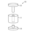
- FIG. 1 is a schematic diagram of a press die used to prepare the sample pellets.
- the composite electrolyte of the present disclosure contains an inorganic solid electrolyte (hereinafter also referred to as “component (X)”) and a molecular crystal as an organic solid electrolyte (hereinafter also referred to as “component (Y)”), and has a porosity of 15% or less.
- component (X) inorganic solid electrolyte
- component (Y) molecular crystal as an organic solid electrolyte
- the porosity of the composite electrolyte exceeds 15%, the ionic conductivity of the composite electrolyte is low and the practicality is poor. From the viewpoint of obtaining a composite electrolyte with excellent ionic conductivity, the porosity of the composite electrolyte is preferably 12% or less, more preferably 10% or less, and even more preferably 8% or less. There is no particular limit to the lower limit of the porosity of the composite electrolyte, and it may be 0% or more.
- the density (D) of the composite electrolyte used to calculate the porosity can be expressed by the following formula using the mass of the composite electrolyte (M, unit: g), the contact area between the composite electrolyte and the electrode (S, unit: cm2 ), and the thickness of the composite electrolyte (L, unit: cm).
- D M / (S x L)
- the theoretical density (D') is a value calculated by multiplying the density of the (X) component and the (Y) component contained in the composite electrolyte by the mass ratio of each component, and the total value of the product.
- the details of the calculation method of the porosity and density (D) are as described in the examples below.
- the porosity of the composite electrolyte can be adjusted, for example, by the temperature of the heat treatment after mixing the (X) component and the (Y) component.
- the inorganic solid electrolyte contained as the (X) component is not particularly limited as long as it is an inorganic solid exhibiting ion conductivity.
- the (X) component include oxide-based solid electrolytes, Sulfide-based solid electrolytes and chloride-based solid electrolytes can be used.
- the component (X) is preferably an oxide-based solid electrolyte or a sulfide-based solid electrolyte, because of its high ionic conductivity. In terms of high safety in the atmosphere, oxide-based solid electrolytes are more preferable.
- the crystal structure of the (X) component is not particularly limited.
- Examples of the crystal structure of the (X) component include a NASICON structure, a LISICON structure, a perovskite structure, and a garnet structure.
- the (X) component include solid electrolytes having a NASICON structure, such as Li1 + xAlxTi2 -x ( PO4 ) 3 (x ⁇ 0, also known as “LTP” or “LATP”), Li1 + xAlxGe2 -x ( PO4 ) 3 (x ⁇ 0, also known as “LGP” or “LAGP”), LiZr2 ( PO4 ) 3 (also known as " LZP "), and Na3Zr2Si2PO12 , which is a NASICON structure .
- NASICON structure such as Li1 + xAlxTi2 -x ( PO4 ) 3 (x ⁇ 0, also known as “LTP” or “LATP”), Li1 + xAlxGe2 -x ( PO4 ) 3 (x ⁇ 0, also known as “LGP” or “LAGP”), LiZr2 ( PO4 ) 3 (also known as " LZP "), and Na3Zr2S
- NZSP N-(n-ZSP)
- oxides in which some of the elements constituting these compounds are substituted with various elements e.g., B, Na, Al, Si, Ca, Ga, Ge, Sc, Fe, Sr, In, Ti, Hf, Sn, V, Nb, Ta, Sb, Bi, W, lanthanoid elements, etc.
- Examples of solid electrolytes having a LISICON structure include Li 14 ZnGe 4 O 16 and oxides in which some of the elements constituting the compound are substituted with the various elements listed above.
- Examples of solid electrolytes having a perovskite structure include Li 0.35 La 0.55 TiO 3 and oxides in which some of the elements constituting this compound are substituted with the various elements listed above.
- Examples of solid electrolytes having a garnet structure include Li 7 La 3 Zr 2 O 12 and Li 5 La 3 Nb 2 O 12 , as well as oxides in which some of the elements constituting these compounds are substituted with the various elements listed above.
- One aspect of the composite electrolyte of the present disclosure is an organic-inorganic hybrid solid electrolyte that includes an inorganic solid electrolyte having a NASICON-type crystal structure and a molecular crystal as an organic solid electrolyte.
- the NASICON-type crystal structure has a three-dimensionally expanded space for alkali metal ions to move, and zirconium (Zr) is stable even under high voltages, making it useful as a solid electrolyte with high operating voltages.
- an oxide having a NASICON-type crystal structure can be preferably used as the inorganic solid electrolyte that is the (X) component.
- the crystal structure of the solid electrolyte can be determined from a diffraction profile obtained by powder X-ray diffraction measurement (XRD).
- oxide (y1) A solid electrolyte represented by the general formula Li 1+x+y-z M1 x Zr 2-x M2 y M3 z P 3-y-z O 12 (wherein M1 contains Fe, In or Al, M2 contains Si, M3 contains W, and x>0, y ⁇ 0, z ⁇ 0, and y+z>0 are satisfied).
- Oxide (y2) A solid electrolyte represented by the general formula: Na3+2x+y+ ⁇ M4xM5yM6zZr2 -x-y-zSi2 + ⁇ P1 - ⁇ O12 (wherein M4 contains an element that becomes a divalent cation, M5 may contain Al and an element that becomes a trivalent cation other than Al, M6 may contain Ti and an element that becomes a tetravalent cation other than Ti, Zr, and Si, and x ⁇ 0, y ⁇ 0, z ⁇ 0, x+y+z>0, and ⁇ >0 are satisfied).
- Oxide (y1) is a solid electrolyte in which, in an oxide having a basic skeleton of LiZr2 ( PO4 ) 3 , a portion of Zr is substituted with M1 (containing Fe, In or Al) and a portion of P is substituted with M2 (containing Si) and/or M3 (containing W).
- M1 may contain Fe or In. That is, M1 may be Fe, In or Al, and may further contain an element that becomes a trivalent cation other than Fe, In or Al together with Fe, In or Al. Examples of elements that become trivalent cations other than Fe, In or Al include Group 13 elements, transition elements (Groups 3 to 11 elements) that become trivalent cations, Sb, Bi, etc.
- M2 may contain Si. That is, M2 may be Si, or may further contain an element other than Si that becomes a tetravalent cation. Examples of elements other than Si that become tetravalent cations include Group 14 elements other than Si, transition elements (Groups 3 to 11 elements) that become tetravalent cations, and Te.
- M3 may contain W. That is, M3 may be W, or may further contain an element other than W that becomes a hexavalent cation. Examples of elements other than W that become hexavalent cations include transition elements (groups 3 to 11 elements) other than W that become hexavalent cations, group 16 elements, etc.
- x, y, and z are not particularly limited as long as x>0, y ⁇ 0, z ⁇ 0, and y+z>0 are satisfied.
- the oxide (y1) is represented by "Li 1+x+y M1 x Zr 2-x M2 y P 3-y O 12 ".
- the oxide (y1) is represented by "Li 1+x-z M1 x Zr 2-x M3 z P 3-z O 12 ".
- the oxide (y1) is represented by "Li 1+x+y-z M1 x Zr 2-x M2 y M3 z P 3-y-z O 12 ".
- x ⁇ 0.3 is satisfied, and it is more preferable that x ⁇ 0.25 is satisfied, in that an impurity phase is unlikely to be formed, and therefore a solid electrolyte exhibiting high ionic conductivity can be obtained.
- x ⁇ 0.01 is satisfied, it is more preferable that x ⁇ 0.05 is satisfied, and it is even more preferable that x ⁇ 0.10 is satisfied.
- the value of y preferably satisfies y ⁇ 0.2, more preferably satisfies y ⁇ 0.15, and even more preferably satisfies y ⁇ 0.10, since y has a dominant effect on the formation of the ⁇ phase, thereby enabling a solid electrolyte with higher ion conductivity to be obtained.
- the lower limit of y preferably satisfies y ⁇ 0.01, and more preferably satisfies y ⁇ 0.03.
- zirconium phosphate oxides having a NASICON type crystal structure can have four phase structures: ⁇ phase, ⁇ ' phase, ⁇ phase, and ⁇ ' phase. Of these, the ⁇ phase has the highest Li ion conductivity because its crystal structure is isotropic.
- z it is preferable that z ⁇ 0.2 is satisfied, more preferably z ⁇ 0.15 is satisfied, and even more preferably z ⁇ 0.10 is satisfied, in that it is possible to suppress the formation of impurity phases and obtain a solid electrolyte that exhibits higher ionic conductivity.
- z>0 it is preferable that the lower limit of z is satisfied, and more preferably z ⁇ 0.01 is satisfied, and even more preferably z ⁇ 0.03 is satisfied.
- the oxide (y2) is a solid electrolyte in which a part of Zr in an oxide having a basic skeleton of Na 3 Zr 2 Si 2 PO 12 is substituted with at least one of M4 (containing an element that becomes a divalent cation), M5 (containing Al), and M6 (containing Ti), and in which the amount of Si in the composition is greater than that of the basic skeleton.
- M4 containing an element that becomes a divalent cation
- M5 containing Al
- M6 containing Ti
- examples of M4 include elements of Group 2, Group 12, and transition elements (elements of Groups 3 to 11) that form divalent cations, as well as Sn and Pd.
- M5 may contain Al. That is, M5 may be Al, or may further contain an element other than Al that becomes a trivalent cation.
- elements other than Al that become trivalent cations include Group 3 elements, Group 13 elements other than Al, transition elements (Groups 3 to 11 elements) that become trivalent cations, Sb, Bi, etc.
- the Group 13 element other than Al is preferably B (boron).
- M6 may contain Ti. That is, M6 may be Ti, or may further contain an element other than Ti, Zr, and Si that becomes a tetravalent cation. Examples of elements other than Ti, Zr, and Si that become a tetravalent cation include Group 14 elements other than Si, and transition elements (Groups 3 to 11 elements) other than Ti and Zr that become a tetravalent cation (Te, Ce, Th), etc.
- oxide (y2) In the general formula of oxide (y2), x, y, and z satisfy x ⁇ 0, y ⁇ 0, z ⁇ 0, and x+y+z>0, and ⁇ is not particularly limited as long as ⁇ >0 is satisfied.
- oxide (y2) is represented by "Na 3+2x+ ⁇ M4 x M6 z Zr 2-x-z Si 2+ ⁇ P 1- ⁇ O 12 ".
- the oxide (y2) is represented by " Na3+2x+y+ ⁇ M4xM5yZr2 - x -ySi2 + ⁇ P1- ⁇ O12 ".
- the oxide (y2) is represented by " Na3+ ⁇ M6zZr2 -zSi2 + ⁇ P1 - ⁇ O12 ".
- x ⁇ 0.3 is satisfied, more preferably that x ⁇ 0.2 is satisfied, and even more preferably that x ⁇ 0.1 is satisfied, in that an impurity phase is unlikely to be formed, and thus a solid electrolyte exhibiting high ionic conductivity can be obtained.
- the lower limit of x is preferably x ⁇ 0.01, more preferably that x ⁇ 0.03 is satisfied, and even more preferably that x ⁇ 0.05 is satisfied.
- y it is preferable that y ⁇ 0.3 is satisfied, more preferably that y ⁇ 0.2 is satisfied, and even more preferably that y ⁇ 0.1 is satisfied, in that the formation of an impurity phase is suppressed and thus a solid electrolyte with higher ionic conductivity can be obtained.
- the lower limit of y is preferable that y ⁇ 0.01 is satisfied, more preferably that y ⁇ 0.03 is satisfied, and even more preferably that y ⁇ 0.05 is satisfied.
- z it is preferable that z ⁇ 0.3 is satisfied, more preferably that z ⁇ 0.2 is satisfied, and even more preferably that z ⁇ 0.1 is satisfied, in that it is possible to suppress the formation of impurity phases and obtain a solid electrolyte that exhibits higher ionic conductivity.
- the lower limit of z is preferable that z ⁇ 0.01 is satisfied, more preferably that z ⁇ 0.03 is satisfied, and even more preferably that z ⁇ 0.05 is satisfied.
- ⁇ since a large amount of Si substitution is thought to decrease ionic conductivity, it is preferable that ⁇ 1.0 is satisfied, more preferably that ⁇ 0.9 is satisfied, even more preferably that ⁇ 0.8 is satisfied, even more preferably that ⁇ 0.7 is satisfied, even more preferably that ⁇ 0.6 is satisfied, and even more preferably that ⁇ 0.5 is satisfied.
- the lower limit of ⁇ is preferably satisfied, more preferably that ⁇ 0.15 is satisfied, more preferably that ⁇ 0.25 is satisfied, and even more preferably that ⁇ 0.3 is satisfied.
- the stoichiometric ratio of O is written as 12, but the stoichiometric ratio of O does not have to be strictly 12 as long as the charge neutrality of the oxide as a whole can be maintained. That is, the O in the oxide (y1) may be a value less than 12 or may be a value greater than 12, as long as the charge neutrality of the oxide (y1) as a whole can be maintained.
- a compound represented by Li 1+x+y-z M1 x Zr 2-x M2 y M3 z P 3-y-z O 12 ⁇ (where 0 ⁇ 1 is satisfied, and M1, M2, M3, x, y, and z are the same as M1, M2, M3, x, y, and z in the above formula shown as the general formula of the oxide (y1)) is also included in the oxide (y1) as long as the charge neutrality of the oxide (y1) as a whole is maintained.
- the number of O in the oxide (y2) may be less than 12 or may be more than 12, so long as the charge neutrality of the oxide (y2) as a whole can be maintained.
- a compound represented by Na3+2x+y+ ⁇ M4xM5yM6zZr2 - x -y-zSi2 + ⁇ P1 - ⁇ O12+ ⁇ (wherein 0 ⁇ 1 is satisfied, and M4, M5, M6 , x, y, z, and ⁇ are the same as M4, M5, M6, x, y, z, and ⁇ in the above formula shown as the general formula of the oxide (y2)) is also included in the oxide (y2) as long as the charge neutrality of the oxide (y2) as a whole can be maintained.
- the method for producing the oxide (y1) and the oxide (y2) is not particularly limited.
- the oxide (y1) and the oxide (y2) can be produced by weighing and mixing the raw materials so as to satisfy the stoichiometric ratio of the composition represented by each of the general formulas above (mixing step), and then firing the resulting mixture (firing step).
- the Li supply component, M1 supply component (Fe supply component, In supply component, or Al supply component), M2 supply component (Si supply component), M3 supply component (W supply component), Zr supply component, and P supply component can be used, whichever corresponds to the element for obtaining the desired oxide (y1).
- the Li supply component, M1 supply component, M2 supply component, Zr supply component, and P supply component are used as raw materials.
- the Li supply component, M1 supply component (Fe supply component, In supply component or Al supply component), M2 supply component, M3 supply component, Zr supply component and P supply component for obtaining the oxide (y1) may be, for example, carbonates, hydrogen carbonates, sulfates, sulfites, nitrates, nitrites, phosphates, acetates, citrates, ammonium salts, oxides, hydroxides, chlorides, sulfides, etc., of these metal elements.
- these supply components may be compounds in which one type of supply component contains two or more elements selected from Li, M1, M2, M3, Zr and P.
- the P supply component it is preferable to use a compound containing one or more elements selected from Li, M1, M2, M3, and Zr. Among them, it is preferable to use a zirconium phosphate compound as the supply component (Zr and P supply component).
- zirconium hydrogen phosphate such as Zr(HPO4)2, Zr(HPO4)2.nH2O
- zirconium phosphate such as Zr3 ( PO4 ) 4
- zirconium hydrogen phosphate such as Zr ( PO4 ) ( H2PO4 ) , Zr( PO4 )(H2PO4)2.nH2O (n is 0 ⁇ n ⁇ 2), HZr2 ( PO4 ) 3 , ZrP2O7 , (ZrO) 2P2O7 , etc.
- Zr(HPO 4 ) 2.nH 2 O which is called layered zirconium phosphate, can be preferably used because the inorganic solid electrolyte is easy to handle during production.
- the Na supply component, M4 supply component, M5 supply component, M6 supply component, Zr supply component, Si supply component, and P supply component which are the supply components corresponding to the elements for obtaining the target oxide (y2).
- the Na supply component, M6 supply component, Zr supply component, Si supply component, and P supply component are used as the raw materials.
- these supply components may be compounds in which one type of supply component contains two or more elements from Na, M4, M5, M6, Zr, Si, and P.
- the raw materials for oxide (y2), Na supply component, M4 supply component, M5 supply component, M6 supply component, Zr supply component, Si supply component and P supply component can be carbonates, hydrogen carbonates, sulfates, sulfites, nitrates, nitrites, phosphates, acetates, citrates, ammonium salts, oxides, hydroxides, chlorides, sulfides, etc. of these metal elements.
- these supply components may be compounds containing two or more elements selected from Na, M4, M5, M6, Zr, Si and P.
- Zirconium phosphate compounds can be preferably used as the P supply component, and layered zirconium phosphate is particularly preferred.
- the raw materials may be mixed by dry mixing, but it is preferable to mix them by wet mixing using a liquid.
- wet mixing the density of the sintered product obtained by the firing process can be increased compared to the case of dry mixing, and the ionic conductivity of the resulting solid electrolyte can also be relatively improved.
- liquid used for wet mixing water, various organic solvents, and mixtures thereof can be used as appropriate.
- the mixture obtained in the mixing step may be fired without molding, or may be molded and then fired.
- the firing temperature is not limited, but may be, for example, 900°C or higher, preferably 1,000°C or higher, more preferably 1,150°C or higher, and even more preferably 1,200°C or higher.
- the upper limit of the firing temperature may be, for example, 1,500°C or lower, preferably 1,400°C or lower, and more preferably 1,350°C or lower.
- the temperature may be increased in stages from a temperature lower than the firing temperature (pre-firing), and the temperature required for firing may finally be maintained.
- the pre-firing product obtained may be crushed before the next firing process.
- firing may be performed in three stages, for example, by performing the first pre-firing in a temperature range of 100°C or more and less than 800°C, the second pre-firing in a temperature range of 800°C or more and less than 1,200°C, and the main firing in a temperature range of 1,200°C or more, and the pre-firing product may be crushed each time the firing temperature range is changed.
- the firing time is not limited, but for example, the pre-firing may be performed for 1 hour to 40 hours and the main firing may be performed for 1 hour to 40 hours.
- the oxide (y1) exhibits high Li ion conductivity
- the oxide (y2) exhibits high Na ion conductivity. Therefore, the oxide (y1) is suitable as a material for a composite electrolyte for an electricity storage device in which the ion conductive carrier is a lithium ion.
- the oxide (y2) is suitable as a material for a composite electrolyte for an electricity storage device in which the ion conductive carrier is a sodium ion.
- the inorganic solid electrolyte obtained by the firing process is preferably pulverized by any method to prepare a powder for use in the manufacture of a composite electrolyte.
- the inorganic solid electrolyte may be pulverized, for example, using a pulverizer such as a ball mill, a bead mill, or a blender.
- the average particle diameter of the inorganic solid electrolyte used in the production of the composite electrolyte is preferably 0.1 ⁇ m or more and 20 ⁇ m or less in volume-based median diameter measured in an aqueous medium.
- the average particle diameter of the inorganic solid electrolyte is in the above range, it is preferable in that a composite electrolyte exhibiting high ionic conductivity while improving the handleability can be obtained.
- the average particle diameter of the inorganic solid electrolyte is more preferably 0.2 ⁇ m or more in volume-based median diameter, and even more preferably 0.3 ⁇ m or more.
- the average particle diameter of the inorganic solid electrolyte is more preferably 15 ⁇ m or less in volume-based median diameter, and even more preferably 10 ⁇ m or less.
- the average particle diameter of the inorganic solid electrolyte is a value measured by laser diffraction/scattering particle diameter measurement. For details of the measurement method, follow the method described in the examples below.
- the content of the inorganic solid electrolyte in the composite electrolyte is preferably 1% by volume or more, more preferably 2% by volume or more, even more preferably 5% by volume or more, and even more preferably 10% by volume or more, based on the total amount of the composite electrolyte.
- the upper limit of the content of the inorganic solid electrolyte is preferably 99% by volume or less, more preferably 95% by volume or less, even more preferably 85% by volume or less, even more preferably 75% by volume or less, even more preferably 70% by volume or less, and even more preferably 65% by volume or less, based on the viewpoint of sufficiently reducing the resistance at the particle interface of the inorganic solid electrolyte and thereby increasing the ion conductivity.
- the inorganic solid electrolyte one type may be used alone, or two or more types may be used in combination.
- the molecular crystal contained as the (Y) component is a solid in which the constituent units in the crystal lattice are regularly arranged.
- an organic solid electrolyte containing an organic molecule and an alkali metal salt as constituent units can be preferably used.
- an organic solid electrolyte containing an organic molecule having at least one atom selected from the group consisting of a sulfur atom, an oxygen atom, a nitrogen atom, and a phosphorus atom (hereinafter also referred to as "(A) organic molecule”) and an alkali metal salt as constituent units can be preferably used.
- the molecular crystal containing the (A) organic molecule and the alkali metal salt has an ion conduction path due to the regular arrangement of the (A) organic molecule and the alkali metal salt as constituent units, and is therefore suitable in that it exhibits excellent ion conductivity.
- the number of at least one type of atom selected from the group consisting of sulfur atoms, oxygen atoms, nitrogen atoms, and phosphorus atoms contained in the (A) organic molecule is not particularly limited.
- the number of at least one type of atom selected from the group consisting of sulfur atoms, oxygen atoms, nitrogen atoms, and phosphorus atoms is preferably 1 to 8, and more preferably 2 to 6, per molecule.
- the (A) organic molecule preferably has 2 or more, and more preferably 2 to 6, of at least one type of atom selected from sulfur atoms, oxygen atoms, and nitrogen atoms in one molecule.
- the molecular weight of the (A) organic molecule is, for example, 300 or less, preferably 250 or less, and more preferably 200 or less.
- the lower limit of the molecular weight of the (A) organic molecule is, for example, 20 or more, preferably 40 or more, and more preferably 50 or more.
- the total number of carbon atoms per molecule of the (A) organic molecule is preferably 10 or less, more preferably 8 or less, and even more preferably 6 or less.
- the total number of carbon atoms per molecule of the (A) organic molecule is preferably 2 or more.
- organic molecules having a sulfur atom such as sulfone, sulfide, thiol, thioester, thiocarbonate, sulfoxide, and sulfamide.
- Organic molecules having nitrogen atoms include nitriles, amines, amides, and the like.
- organic molecules having a phosphorus atom include phosphines, phosphine oxides, and phosphinimines.
- organic molecules having an oxygen atom examples include organic molecules having an oxygen atom among the examples of organic molecules having a sulfur atom, organic molecules having an oxygen atom among the examples of organic molecules having a nitrogen atom, and organic molecules having an oxygen atom among the examples of organic molecules having a phosphorus atom, as well as ethers, esters, ketones, carbonates, etc.
- the organic molecule (A) constituting the molecular crystal may be one type alone or two or more types.
- the (A) organic molecule is at least one selected from the group consisting of organic molecules having sulfur atoms and oxygen atoms, organic molecules having nitrogen atoms, and organic molecules having phosphorus atoms.
- a sulfone As the organic molecule having a sulfur atom and an oxygen atom, a sulfone can be preferably used.
- a preferred example of the sulfone is a compound represented by the following formula (1):
- R 1 and R 2 are each independently an alkyl group or an alkoxy group, or R 1 and R 2 are bonded together to form a cyclic structure, and the total number of carbon atoms in formula (1) is 2 to 16. Examples of such molecules include those represented by the following formula:
- the molecule represented by the above formula (1) (hereinafter also referred to as "(A-1) molecule”) is a chain or cyclic molecule having a sulfonyl group (-SO 2 -).
- R 1 and R 2 in the above formula (1) are alkyl groups or alkoxy groups, the alkyl groups and alkoxy groups may be linear or branched.
- the number of carbon atoms in each of the alkyl groups and alkoxy groups i.e., the number of carbon atoms in each of the groups R 1 and R 2
- each of R 1 and R 2 preferably has a carbon atom number of 1 to 3, more preferably 1 or 2.
- R 1 and R 2 in the above formula (1) represent a cyclic structure formed by bonding R 1 and R 2
- the cyclic structure may have a saturated ring skeleton, or may have an unsaturated bond in the ring skeleton.
- the cyclic structure formed by bonding R 1 and R 2 may be a structure in which an alkyl group (e.g., a methyl group or an ethyl group) is bonded to the ring skeleton.
- the number of carbon atoms in the cyclic structure formed by bonding R 1 and R 2 is preferably 2 to 8, more preferably 2 to 6, and even more preferably 3 to 5.
- R1 and R2 in the above formula (1) represent a cyclic structure formed by bonding R1 and R2 together, and it is more preferable that the cyclic structure has a saturated ring skeleton.
- the total number of carbon atoms in the above formula (1) is 2 to 16. From the viewpoint of promoting crystallization of the mixture of the supply component of the (A-1) molecule and the alkali metal salt during the production of molecular crystals, the total number of carbon atoms in the above formula (1) is preferably 2 to 8, more preferably 2 to 6, and even more preferably 2 to 5.
- (A-1) molecule examples include, when R 1 and R 2 in the above formula (1) are each an alkyl group or an alkoxy group, dimethyl sulfone, ethyl methyl sulfone, diethyl sulfone, dioctyl sulfone, dimethyl sulfate, diethyl sulfate, etc.
- Examples of the (A-1) molecule include, when R 1 and R 2 in the above formula (1) are each a cyclic structure formed by bonding R 1 and R 2 , tetrahydrothiophene 1,1-dioxide, 3-methylsulfolane, 3-sulfolene, 1,3-propane sultone, 1,4-butane sultone, 1,3,2-dioxathiolane 2,2-dioxide, etc.
- the (A-1) molecule constituting the molecular crystal may be one type alone or a combination of two or more types.
- nitrile As the organic molecule having a nitrogen atom, a nitrile can be preferably used.
- a preferred example of the nitrile is a compound represented by the following formula (2): (In formula (2), R3 represents a hydrocarbon chain, and R4 and R5 each independently represent a hydrogen atom, an alkyl group, or a cyano group, with the proviso that the total number of carbon atoms in formula (2) is 16 or less.) Examples of such molecules include those represented by the following formula:
- the molecule represented by the above formula (2) (hereinafter also referred to as "(A-2) molecule”) is a molecule having two or more cyano groups (-CN).
- R 3 in the above formula (2) may be a saturated hydrocarbon chain or may have an unsaturated bond. It is preferable that R 3 represents a saturated hydrocarbon chain, since a molecular crystal having excellent ion conductivity can be obtained.
- the number of carbon atoms in R 3 is, for example, 1 to 10, preferably 1 to 6, and more preferably 2 to 4.
- R4 or R5 is an alkyl group
- the alkyl group may be linear or branched. It is preferably linear.
- the number of carbon atoms in each of R4 and R5 is preferably 0 to 3, more preferably 0 or 1, from the viewpoint of causing crystallization by mixing the supply component of the (A-2) molecule with an alkali metal salt during production of the molecular crystal.
- the total number of carbon atoms in the above formula (2) is preferably 8 or less, and more preferably 6 or less.
- the (A-2) molecule include succinonitrile, adiponitrile, 3-hexenedinitrile, 1,3,5-pentanetricarbonitrile, tert-butylmalononitrile, 1,2,2,3-propanetetracarbonitrile, etc.
- the (A-2) molecule constituting the molecular crystal may be one type alone or a combination of two or more types.
- organic molecules having a phosphorus atom examples include ethylene bis(dimethylphosphine), ethylene bis(diphenylphosphine), methyl(diphenyl)phosphine oxide, triphenylphosphine oxide, methyl(diphenyl)phosphine imine, and triphenylphosphine imine.
- the organic molecule (A) is preferably at least one selected from the group consisting of sulfones and nitriles among the above.
- the (A-1) molecule is more preferable, a molecule showing a cyclic structure formed by bonding R 1 and R 2 in the above formula (1) is more preferable, and it is even more preferable that the cyclic structure has a saturated ring skeleton.
- the alkali metal salt is not particularly limited as long as it is a salt that generates an alkali metal ion.
- Examples of the alkali metal salt include lithium salt, sodium salt, and potassium salt.
- alkali metal salts include lithium salts such as Li2CO3 , LiBr , LiCl, LiI, LiSCN , LiBF4 , LiAsF6, LiClO4 , CH3COOLi , CF3COOLi , LiCF3SO3, LiPF6 , LiC( CF3SO2 ) 3 , lithium bis( fluorosulfonyl ) imide (Li + ( FSO2 ) 2N- ) , lithium bis(trifluoromethanesulfonyl)imide (Li + ( CF3SO2 ) 2N- ) , and lithium (fluorosulfonyl)(trifluoromethanesulfonyl)imide; and salts of the anions of these lithium salts with alkali metals other than lithium (e.g., sodium, potassium, etc.).
- the lithium salt or sodium salt is preferred since it is possible to obtain a molecular crystal having high ion dissoci
- the alkali metal salts constituting the molecular crystal preferably contain imide-based alkali metal salts, since this can increase the ionic conductivity of the molecular crystal.
- imide-based lithium salts or imide-based sodium salts are preferred, since they have high ionic dissociation properties.
- lithium bis(fluorosulfonyl)imide lithium bis(trifluoromethanesulfonyl)imide or lithium (fluorosulfonyl)(trifluoromethanesulfonyl)imide is particularly preferred, lithium bis(fluorosulfonyl)imide or lithium bis(trifluoromethanesulfonyl)imide is more preferred, and lithium bis(fluorosulfonyl)imide is even more preferred.
- sodium bis(fluorosulfonyl)imide, sodium bis(trifluoromethanesulfonyl)imide or sodium trifluoromethanesulfonimide is preferred, sodium bis(fluorosulfonyl)imide or sodium bis(trifluoromethanesulfonyl)imide is more preferred, and sodium bis(fluorosulfonyl)imide is even more preferred.
- the molecular weight of the alkali metal salt is, for example, 500 or less, preferably 400 or less, more preferably 350 or less, and even more preferably 300 or less.
- the lower limit of the molecular weight of the alkali metal salt is, for example, 20 or more, preferably 50 or more, more preferably 100 or more, and even more preferably 150 or more.
- the alkali metal salt constituting the molecular crystal may be one type alone or two or more types.
- the melting point of the alkali metal salt is, for example, 60°C or higher, preferably 70°C or higher, and more preferably 80°C or higher. There is no particular upper limit to the melting point of the alkali metal salt, but it may be, for example, 300°C or lower, or 250°C or lower.
- the method for producing the molecular crystal which is the component (Y) constituting the composite electrolyte of the present disclosure, is not particularly limited.
- the molecular crystal can be produced using a supply component for the organic molecule (A) (hereinafter also referred to as "organic substance (A)") and an alkali metal salt.
- the molecular crystal containing (A) an organic molecule and an alkali metal salt as constituent units is preferably obtained by a method of mixing (A) an organic substance and an alkali metal salt and then heating them. Specifically, it is preferably produced by a method including the following mechanical mixing step and heating step.
- Mechanical mixing step a step of mixing (A) an organic substance and an alkali metal salt while applying mechanical energy to obtain a mixture.
- Heating step a step of heating the mixture obtained by the mechanical mixing step.
- the compounding ratio when mixing the (A) organic material and the alkali metal salt may be set according to the types of the (A) organic material and the alkali metal salt, and is not particularly limited.
- the compounding ratio of the (A) organic material and the alkali metal salt may be, for example, 0.1 to 10 moles of the (A) organic material per mole of the alkali metal salt.
- the compounding ratio of the (A) organic material and the alkali metal salt is preferably 0.2 to 5 moles of the (A) organic material per mole of the alkali metal salt, more preferably 0.25 to 4 moles, and even more preferably 0.5 to 2 moles.
- a substance other than the (A) organic substance and the alkali metal salt e.g., a sulfur-containing organic molecule other than the (A) organic substance
- the alkali metal salt e.g., a sulfur-containing organic molecule other than the (A) organic substance
- the amount of the substance other than the (A) organic substance and the alkali metal salt used is preferably 0.1 mol or less, and more preferably 0.05 mol or less, per 1 mol of the total amount of the (A) organic substance and the alkali metal salt.
- the method for mixing the (A) organic substance and the alkali metal salt while applying mechanical energy is not particularly limited.
- the (A) organic substance and the alkali metal salt can be mixed using various devices such as a ball mill, a bead mill, a blender, a homogenizer, a stamp mill, a homomixer, a dispersing mixer, etc.
- the (A) organic substance and the alkali metal salt can be mechanically mixed using a mortar and pestle.
- the (A) organic substance and the alkali metal salt can be mechanically mixed in a dry or wet manner.
- the (A) organic substance and the alkali metal salt can be mechanically mixed at room temperature or at a low temperature.
- the (A) organic substance in a liquid state can be mechanically mixed with the alkali metal salt.
- the (A) organic substance in a solid state can be mechanically mixed with the alkali metal salt at a temperature lower than the melting point of the (A) organic substance.
- the mechanical mixing of the (A) organic substance and the alkali metal salt may be performed while heating.
- the mechanical mixing step is preferably performed at a temperature lower than the heating temperature in the subsequent heating step.
- the mechanical mixing step is performed, for example, at 50°C or lower, preferably at 40°C or lower, and more preferably at 35°C or lower.
- the time for which mechanical mixing is performed depends on the amount and type of the (A) organic substance and alkali metal salt used, but may be, for example, 1 to 60 minutes, or 1 to 30 minutes.
- the mixture of (A) organic matter and alkali metal salt obtained by mechanical mixing preferably has a melting point of 40°C or higher, more preferably 50°C or higher, and even more preferably 55°C or higher.
- the melting point of the mixture is preferably 110°C or lower, more preferably 100°C or lower, and even more preferably 95°C or lower, in order to suppress decomposition of molecular crystals accompanying volatilization or sublimation of (A) organic matter or (A) organic molecules in the heating step following the mechanical mixing step.
- the melting point of the mixture of (A) organic matter and alkali metal salt is a value obtained by differential scanning calorimetry (DSC). Details of the measurement method follow the method described in the Examples below.
- the heating step after the mechanical mixing step, the mixture obtained by the mechanical mixing step is heated.
- the method of heating the mixture is not particularly limited.
- the heating temperature of the mixture can be appropriately set depending on the type of the organic material (A) and the alkali metal salt used as the raw material. From the viewpoint of making the organic material (A) and the alkali metal salt in the mixture more uniform, it is preferable to heat the mixture at a temperature equal to or higher than the melting point of the mixture of the organic material (A) and the alkali metal salt obtained by mechanical mixing in this heating step.
- the heating temperature By setting the heating temperature to equal to or higher than the melting point of the mixture, the mixture melts, thereby promoting uniform mixing of the organic material (A) and the alkali metal salt.
- the temperature at which the mixture is heated is preferably higher than the melting point of the mixture, from the viewpoint of homogenizing the organic substance (A) and the alkali metal salt in the mixture by melting the mixture.
- the heating temperature of the mixture is more preferably 5°C or higher than the melting point of the mixture (unit: °C), and even more preferably 7°C or higher.
- the melting point of the mixture when the melting point of the mixture is expressed as Mp (unit: °C), from the viewpoint of suppressing volatilization and sublimation of the components contained in the mixture, it is preferable to set it to (Mp + 20) °C or lower, and more preferably (Mp + 15) °C or lower.
- the heating time is not particularly limited as long as it is sufficient to homogenize the organic substance (A) and the alkali metal salt in the mixture.
- the heating time is, for example, 1 minute to 3 hours, preferably 15 minutes to 2 hours, and more preferably 30 minutes to 2 hours.
- the heat treatment is usually performed under normal pressure, but may be performed under pressure or reduced pressure.
- the stirring method is not particularly limited, and examples include a magnetic stirrer, a stirring rod, a stirrer with stirring blades, and external circulation stirring. Stirring may also be performed by mechanical mixing operations that provide greater shear force, such as a homomixer, a dispersing mixer, or a homogenizer.
- the temperature of the heated mixture is lowered, so that the heated mixture crystallizes and the desired molecular crystal can be obtained.
- the mixture may be gradually cooled (e.g., the temperature is slowly lowered at room temperature over 1 to 48 hours).
- the heated mixture may be rapidly cooled (e.g., the heated mixture is placed in a thermostatic bath at a temperature lower than room temperature (e.g., 15°C or lower) for a short period of time). From the viewpoint of favorable crystallization of the heated mixture, it is preferable to cool the heated mixture by gradually lowering the temperature of the mixture.
- the product obtained by this manufacturing method is (A) a molecular crystal containing an organic molecule and an alkali metal salt can be detected by performing powder X-ray diffraction measurement of the product. Details of the measurement method follow the method described in the Examples below.
- a manufacturing method including a mechanical mixing step and a heating step it is believed that in the production of molecular crystals, the mechanical mixing performed before the heat treatment generates an intermolecular interaction between the alkali metal ions derived from the alkali metal salt and the organic substance (A). Therefore, in a manufacturing method in which heat treatment is performed after mechanical mixing, sublimation and volatilization of the organic substance (A) during the heat treatment is suppressed, which is believed to suppress the variation in the composition of the molecular crystals. Furthermore, it is believed that suppressing the variation in the composition of the molecular crystals forms a uniform ion conduction path, making it possible to produce molecular crystals that exhibit excellent ion conductivity.
- the content of the molecular crystals, which are the (Y) component is preferably 1% by volume or more, more preferably 5% by volume or more, even more preferably 15% by volume or more, even more preferably 25% by volume or more, still more preferably 30% by volume or more, and even more preferably 35% by volume or more, relative to the total amount of the composite electrolyte, in order to sufficiently reduce the resistance at the particle interface of the inorganic solid electrolyte, thereby increasing the ionic conductivity, and improving the formability of the composite electrolyte.
- the upper limit of the content of the molecular crystals is preferably 99% by volume or less, more preferably 98% by volume or less, even more preferably 95% by volume or less, and even more preferably 90% by volume or less, relative to the total amount of the composite electrolyte.
- the composite electrolyte of the present disclosure may further contain other components in addition to the inorganic solid electrolyte and the molecular crystals, as long as the effects of the present disclosure are not impaired.
- other components include molecular crystals different from the molecular crystals of the present disclosure (i.e., component (Y)), polymer solid electrolytes, polymer gel electrolytes, binders, etc.
- component (Y) molecular crystals different from the molecular crystals of the present disclosure
- component (Y) component (Y)
- polymer solid electrolytes polymer gel electrolytes, binders, etc.
- the content of other components is preferably 1 vol. % or less, and more preferably 0.5 vol. % or less, of the total amount of the inorganic solid electrolyte and the molecular crystals.
- the composite electrolyte of the present disclosure can be produced by mixing an inorganic solid electrolyte as component (X) with a molecular crystal as component (Y).
- the composite electrolyte of the present disclosure is preferably produced by a method including the following mixing step and heating step.
- Mixing step A step of mixing an inorganic solid electrolyte with molecular crystals to obtain a mixture.
- Heating step A step of heating the mixture of an inorganic solid electrolyte with molecular crystals.
- the inorganic solid electrolyte and the molecular crystals may be mixed uniformly, and the method is not particularly limited.
- the inorganic solid electrolyte and the molecular crystals may be mixed in a dry or wet manner. Dry mixing is preferable.
- the mechanical mixing step is advantageous in that the molecular crystals as raw materials can be mixed uniformly with the inorganic solid electrolyte while being melted by the heat of mechanical mixing, and that a composite electrolyte with a sufficiently small porosity can be obtained because a solvent is not required during mixing.
- the description of the mechanical mixing step in the method for producing molecular crystals can be applied.
- Heating step After the above-mentioned mixing step is performed, the mixture of the inorganic solid electrolyte and the molecular crystals obtained in the mixing step is heated. This heating step is believed to reduce the porosity by filling the gaps in the inorganic solid electrolyte with the molecular crystals, thereby reducing the interface resistance and providing a composite electrolyte with excellent ion conductivity.
- the mixture (typically particulate) obtained in the mixing step may be used as is and heated.
- the mixture of the inorganic solid electrolyte and the molecular crystals may be molded, and the molded body obtained thereby may be heated.
- the molding method is not particularly limited, and known methods such as extrusion molding, injection molding, pressure molding, slip casting, mold cast molding, and tape molding can be used. Among these, it is preferable to obtain a molded body by pressure molding, since the porosity of the composite electrolyte can be made as small as possible and ion conduction paths are easily formed.
- the shape of the molded body is not particularly limited, and can be appropriately set according to the shape of the applied electricity storage device.
- the shape of the molded body is, for example, rectangular or circular.
- the heating temperature when heating the mixture of inorganic solid electrolyte and molecular crystals can be set appropriately depending on the types of inorganic solid electrolyte and molecular crystals used as raw materials. From the viewpoint of filling the gaps in the inorganic solid electrolyte with molecular crystals and obtaining a composite electrolyte (i.e., a solid electrolyte) with a small porosity, it is preferable to heat the mixture at a temperature at which the molecular crystals do not seep out of the mixture when heated.
- the heating step in the manufacture of the composite electrolyte it is preferable to heat the mixture of the inorganic solid electrolyte and the molecular crystal at or near the melting point of the molecular crystal (for example, in the case of a molecular crystal containing (A) an organic molecule and an alkali metal salt as constituent units, the melting point of the mixture of the raw material (A) organic substance and the alkali metal salt).
- the heating temperature of the mixture of the inorganic solid electrolyte and the molecular crystal is preferably in the range of (Mr ⁇ 15) °C, and more preferably in the range of (Mr ⁇ 10) °C.
- the heating time is, for example, 1 to 72 hours, preferably 2 to 48 hours, and more preferably 5 to 36 hours.
- the heating process may be performed under normal pressure, or under pressure or reduced pressure.
- the temperature of the mixture is lowered after heating, the mixture may be gradually cooled (for example, air-cooled) or may be rapidly cooled using a cooler or the like.
- the molded body may be used as it is as the solid electrolyte layer of the electricity storage device.
- a plurality of molded bodies may be stacked to form the solid electrolyte layer of the electricity storage device.
- the thickness of the molded body is, for example, 5 to 5,000 ⁇ m, preferably 5 to 3,500 ⁇ m, and more preferably 10 to 3,000 ⁇ m.
- the composite electrolyte obtained as described above exhibits high ionic conductivity. Therefore, by using the composite electrolyte of the present disclosure as an electrolyte material for an electricity storage device, an electricity storage device with high ionic conductivity can be obtained.
- the ionic conductivity measured at 25° C. using an AC impedance method for a molded body having a thickness of about 1,000 ⁇ m (specifically, 1,000 ⁇ 50 ⁇ m) made of the composite electrolyte of the present disclosure is preferably 1 ⁇ 10 ⁇ 6 S/cm or more.
- the ionic conductivity under the same conditions is more preferably 2 ⁇ 10 ⁇ 6 S/cm or more, and even more preferably 5 ⁇ 10 ⁇ 6 S/cm or more.
- the ionic conductivity can be measured by AC impedance measurement. Details of the measurement method follow the method described in the examples below.
- the power storage device of the present disclosure includes the composite electrolyte of the present disclosure.
- Examples of the device include a secondary battery and a capacitor.
- the device is a secondary battery
- one embodiment of the device is an all-solid-state battery, and a lithium ion secondary battery or a sodium ion secondary battery is preferable in terms of excellent ion conductivity.
- An all-solid-state secondary battery is a laminate comprising electrodes consisting of a positive electrode and a negative electrode, and a solid electrolyte layer, with the solid electrolyte layer being disposed between the positive electrode and the negative electrode so that the solid electrolyte layer is in contact with the electrode.
- the materials constituting the positive electrode and the negative electrode there are no particular limitations on the materials constituting the positive electrode and the negative electrode, and any suitable material may be selected from materials known as electrode materials for secondary batteries.
- a metal foil such as aluminum or stainless steel may be used as the positive electrode current collector.
- a metal foil such as copper foil or lithium foil may be used as the negative electrode current collector.
- the solid electrolyte layer is formed from the composite electrolyte of the present disclosure (i.e., a composite electrolyte containing an inorganic solid electrolyte and a molecular crystal).
- the thickness of the solid electrolyte layer is not particularly limited and can be set appropriately depending on the application of the secondary battery.
- the thickness of the solid electrolyte layer is, for example, 5 to 5,000 ⁇ m, preferably 5 to 3,500 ⁇ m, and more preferably 10 to 3,000 ⁇ m.
- the method for producing the all-solid-state secondary battery is not particularly limited, and a known method can be appropriately adopted depending on the battery structure, etc.
- a laminate including a positive electrode, a solid electrolyte layer, and a negative electrode may be produced by sandwiching a solid electrolyte layer formed by the composite electrolyte of the present disclosure between a positive electrode and a negative electrode, and preferably performing a pressure treatment for bonding.
- a laminate including a positive electrode, a solid electrolyte layer, and a negative electrode may be produced by sandwiching an electrolyte material including a particulate composite electrolyte between a positive electrode and a negative electrode and containing the electrolyte material in a container, performing a heat treatment on the container to obtain the above-mentioned composite electrolyte, and preferably performing a pressure treatment for bonding.
- a laminate including a positive electrode, a solid electrolyte layer, and a negative electrode is usually contained in a case and used as a secondary battery.
- the ion-conducting carrier in this device is not particularly limited.
- the device may also be a capacitor.
- One form of capacitor is one that includes an anode body, a cathode body, and a solid electrolyte layer, with the solid electrolyte layer disposed between the anode body and the cathode body so that the solid electrolyte layer is in contact with the electrode.
- An electricity storage device having a solid electrolyte layer formed using the composite electrolyte of the present disclosure can be used for a variety of purposes. Specifically, it can be used as a power source for, for example, various mobile devices such as mobile phones, personal computers, smartphones, game devices, and wearable devices; various moving objects such as electric cars, hybrid cars, robots, and drones; various electric and electronic devices such as digital cameras, video cameras, music players, power tools, and home appliances; etc.
- various mobile devices such as mobile phones, personal computers, smartphones, game devices, and wearable devices
- various moving objects such as electric cars, hybrid cars, robots, and drones
- various electric and electronic devices such as digital cameras, video cameras, music players, power tools, and home appliances; etc.
- the resulting mixture was dried at 100°C for 2 hours, then transferred to an alumina crucible (capacity 30 mL), heated to 1,250°C over 5.5 hours, and held for 5 hours to perform firing (firing step). The mixture was then allowed to cool to room temperature (25°C) to obtain a fired product. The fired product was pulverized in a mortar to obtain an inorganic solid electrolyte ISE-1.
- the value of n in Zr( HPO4 ) 2.nH2O was set to 1.0 .
- the main crystal phase of the inorganic solid electrolyte ISE-1 belongs to monoclinic or rhombohedral LiZr 2 P 3 O 12 , and that the inorganic solid electrolyte ISE-1 has a NASICON type crystal structure.
- the inorganic solid electrolyte ISE-1 was diluted with pure water in a 30 mL sample bottle to obtain a 1% by mass dispersion. The diluted dispersion was irradiated with 1 kHz ultrasound for 10 minutes.
- the volume-based median diameter (D50) of the inorganic solid electrolyte ISE-1 was measured at room temperature (25°C) using a laser diffraction/scattering particle size measuring device MT-3000 (manufactured by Microtrac) with the dispersion immediately after the ultrasound irradiation as a measurement sample. The particle size measurement was performed twice, and the average value was adopted as the volume-based median diameter of the inorganic solid electrolyte ISE-1.
- the volume-based median diameter of the inorganic solid electrolyte ISE-1 was 1.4 ⁇ m.
- a sample pellet was prepared in a dry room with a dew point of -40°C or less.
- the die set 11 containing 0.150 g of inorganic solid electrolyte ISE-1 was placed on the lower punch 13, and the upper punch 12 was placed on the die set 11.
- the inorganic solid electrolyte ISE-1 was compressed for 1 minute at a pressure of 10 MPa using a hydraulic press to obtain a circular sample pellet with a diameter of 1 cm and a thickness of 1000 ⁇ m.
- the sample pellet was enclosed in an all-solid-state battery evaluation cell (KP-SolidCell, manufactured by Hosen Co., Ltd.) in a dry room with a dew point of -40°C or less.
- an all-solid-state battery evaluation cell in which the sample pellet was enclosed, the resistance value at 25° C. was measured by AC impedance measurement.
- the ionic conductivity ( ⁇ ) was calculated according to the following formula (1).
- ⁇ L/(R ⁇ S)...(1)
- ⁇ ionic conductivity (unit: S/cm)
- R represents resistance (unit: ⁇ )
- S represents the cross-sectional area of the sample pellet (unit: cm 2 )
- L represents the distance between the electrodes (unit: cm).)
- the ionic conductivity ( ⁇ ISE ) of the inorganic solid electrolyte ISE-1 at 25° C. was 2.0 ⁇ 10 ⁇ 7 S/cm.
- the all-solid-state battery evaluation cell after the ionic conductivity measurement was disassembled to take out the inorganic solid electrolyte ISE-1 obtained in Production Example 1.
- the thickness (L) of the inorganic solid electrolyte ISE-1 was measured using a film thickness meter (manufactured by Mitutoyo Corporation) and found to be 928 ⁇ m.
- the density (D ISE ) of the inorganic solid electrolyte ISE-1 was calculated using the following formula (2).
- D ISE M ISE / (S ISE ⁇ L ISE ) ...(2)
- D ISE represents the density of the inorganic solid electrolyte (unit: g cm ⁇ 3 )
- M ISE represents the mass of the inorganic solid electrolyte (unit: g)
- S ISE represents the contact area between the electrode and the inorganic solid electrolyte (unit: cm 2 )
- L ISE represents the thickness of the inorganic solid electrolyte (unit: cm).
- the porosity ( ⁇ ISE ) of the inorganic solid electrolyte ISE-1 obtained above was calculated from the density (D ISE ) according to the following formula (3), and was found to be 35%.
- ⁇ ISE (1-D ISE /D' ISE ) ⁇ 100...(3)
- ⁇ ISE represents the porosity (unit: %)
- D ISE represents the density of the inorganic solid electrolyte (unit: g ⁇ cm ⁇ 3 )
- D′ ISE represents the theoretical density of the inorganic solid electrolyte (the theoretical density of the inorganic solid electrolyte ISE-1 is 3.17, unit: g ⁇ cm ⁇ 3 ).)
- the theoretical density D' ISE was calculated from the information of the crystal phase identified by the XRD measurement using the following formula (4).
- D' ISE N/V...(4)
- N represents the atomic mass (unit: g) in the unit lattice of the inorganic solid electrolyte
- V represents the volume (unit: cm 3 ) of the unit lattice of the inorganic solid electrolyte.
- Inorganic solid electrolytes (referred to as “inorganic solid electrolyte ISE-2”, “inorganic solid electrolyte ISE-3”, and “inorganic solid electrolyte ISE-4", respectively) were obtained by the same operation as in Production Example 1, except that the types and amounts of raw materials were changed as shown in Table 1.
- the volume-based median diameter and ionic conductivity ( ⁇ ISE ) of the inorganic solid electrolyte ISE-2, inorganic solid electrolyte ISE-3, and inorganic solid electrolyte ISE- 4 obtained in each Production Example were measured in the same manner as in Production Example 1. The results are shown in Table 1.
- the inorganic solid electrolyte ISE-2, inorganic solid electrolyte ISE-3, and inorganic solid electrolyte ISE-4 were subjected to powder X-ray diffraction measurement in the same manner as in Production Example 1.
- the main crystal phase of the inorganic solid electrolyte ISE-2 and the inorganic solid electrolyte ISE-3 was assigned to monoclinic or rhombohedral Na 3 Zr 2 Si 2 PO 12
- the main crystal phase of the inorganic solid electrolyte ISE-4 was assigned to monoclinic or rhombohedral LiZr 2 P 3 O 12. From these results, it was confirmed that the inorganic solid electrolyte ISE-2, inorganic solid electrolyte ISE-3, and inorganic solid electrolyte ISE-4 have a NASICON type crystal structure.
- the melting point of the mixture was measured using a differential scanning calorimeter (manufactured by TA Instruments, DSC250, measurement atmosphere: under nitrogen atmosphere) at a heating rate of 10 ° C. per minute, and a large endothermic peak (melting point) was observed at 60 ° C.
- the mixture was transferred to a vial and stirred with a magnetic stirrer set at 80° C. for 1 hour, and it was confirmed that the mixture was dissolved uniformly (heating step). Thereafter, the resulting molten material was allowed to cool to room temperature, and a white solid was obtained.
- sample pellets were prepared in a dry room with a dew point of -40°C or less.
- a die set 11 containing 0.0200 g of a white solid (organic solid electrolyte OSE-1) was placed on the lower punch, and an upper punch 13 was placed on the die set 11.
- the white solid was compressed for 1 minute at a pressure of 10 MPa using a hydraulic press to obtain a circular sample pellet with a diameter of 1 cm and a thickness of 200 ⁇ m.
- the sample pellet was enclosed in an all-solid-state battery evaluation cell (KP-SolidCell, manufactured by Hosen Co., Ltd.) in a dry room with a dew point of -40°C or less.
- the ionic conductivity was measured using an all-solid-state battery evaluation cell in which the sample pellets were sealed.
- the resistance value was measured by AC impedance measurement while the sealed cell in which the sample pellets were sealed was heat-treated in a thermostatic bath at 40° C. (corresponding to the heat treatment temperature in Table 2). The heat treatment was terminated when the resistance value became constant.
- the resistance value at 25° C. was measured by AC impedance measurement.
- the ionic conductivity ( ⁇ ) was calculated by the above formula (3).
- the AC impedance measurement for calculating the ionic conductivity was performed after the cell was held at the measurement temperature in a thermostatic bath for 2 hours.
- the ionic conductivity ( ⁇ OSE ) of the organic solid electrolyte OSE-1 at 25° C. was 3.9 ⁇ 10 ⁇ 5 S/cm.
- the all-solid-state battery evaluation cell after the ionic conductivity measurement was disassembled to take out the organic solid electrolyte OSE-1 obtained in Production Example 5.
- the thickness (L OSE ) of the organic solid electrolyte OSE-1 was measured using a film thickness meter (manufactured by Mitutoyo Corporation) and found to be 171 ⁇ m.
- the density (D OSE ) of the organic solid electrolyte was calculated using the following formula (5).
- D ⁇ SE M ⁇ SE / (S ⁇ SE ⁇ L ⁇ SE ) ...(5)
- D OSE represents the density of the organic solid electrolyte (unit: g cm -3 )
- M OSE represents the mass of the organic solid electrolyte (unit: g)
- S represents the contact area between the electrode and the organic solid electrolyte (unit: cm 2 )
- L OSE represents the thickness of the organic solid electrolyte (unit: cm).
- the porosity ( ⁇ OSE ) of the organic solid electrolyte OSE-1 obtained above was calculated from the density (D OSE ) according to the following formula (6), and was found to be 0%.
- ⁇ ⁇ SE (1-D ⁇ SE /D' ⁇ SE ) ⁇ 100...(6)
- ⁇ OSE represents the porosity (unit: %)
- D OSE represents the density of the organic solid electrolyte (unit: g ⁇ cm ⁇ 3 )
- D′ OSE represents the theoretical density of the organic solid electrolyte.
- the theoretical density D' OSE was calculated from the information of the crystal phase identified by the XRD measurement using the following formula (7).
- N represents the atomic mass (unit: g) in the unit lattice of the organic solid electrolyte
- V represents the volume (unit: cm 3 ) of the unit lattice of the organic solid electrolyte.
- each of the white solids was a molecular crystal composed of an organic molecule and an alkali metal salt (referred to as "Organic Solid Electrolyte OSE-2,””Organic Solid Electrolyte OSE-3,” and “Organic Solid Electrolyte OSE-4,” respectively).
- the ionic conductivity ( ⁇ ⁇ E ) at 25° C. was measured using the white solids of each Production Example (organic solid electrolyte OSE-2, organic solid electrolyte OSE-3, organic solid electrolyte OSE-4) at the heat treatment temperatures shown in Table 2.
- the measurement results of the ionic conductivity ( ⁇ ⁇ E ) are shown in Table 2 together with the measurement results of the melting points of the mixtures of organic molecules and alkali metal salts obtained by the mechanical mixing step.
- the porosity of the organic solid electrolytes was measured by the same method as in Production Example 5.
- the porosity ( ⁇ ⁇ E ) of the organic solid electrolytes OSE-2 and OSE-3 was both 0%.
- Example 1 Production of Composite Electrolyte HSE-1
- 0.200 g of Li1.25In0.2Zr1.8Si0.05P2.95O12 inorganic solid electrolyte ISE- 1 obtained in Production Example 1
- 0.0938 g of Li( FSI )(SN) 2 organic solid electrolyte OSE -1 obtained in Production Example 5
- sample pellets made of a mixture of an inorganic solid electrolyte and an organic solid electrolyte were prepared according to the following procedure. First, a die set 11 containing 0.150 g of the mixture was placed on the lower punch 13, and the upper punch 12 was placed on the die set 11. The mixture was compressed for 1 minute at a pressure of 10 MPa using a hydraulic press to obtain a circular sample pellet having a diameter of 1 cm and a thickness of 1,000 ⁇ m.
- the sample pellets were enclosed in an all-solid-state battery evaluation cell (KP-SolidCell, manufactured by Hosen Co., Ltd.) and sealed in a dry room with a dew point of -40°C or less.
- the all-solid-state battery evaluation cell containing the sample pellets was heat-treated in a thermostatic chamber at 55°C (corresponding to the temperature in the heating step in Table 3) (heating step), and the resistance value was measured by AC impedance measurement while the heat treatment was being performed. When the resistance value became constant, the heat treatment was terminated, and the cell was air-cooled to 25°C to obtain a composite electrolyte (referred to as composite electrolyte HSE-1).
- composite electrolyte HSE-1 composite electrolyte
- D SE M SE /(S SE ⁇ L SE )...(8)
- D SE represents the density of the composite electrolyte (unit: g cm ⁇ 3 )
- M SE represents the mass of the composite electrolyte (unit: g)
- S SE represents the contact area between the electrode and the composite electrolyte (unit: cm 2 )
- L SE represents the thickness of the composite electrolyte (unit: cm).
- the porosity ( ⁇ SE ) of the composite electrolyte HSE-1 obtained in Example 1 was calculated from the density (D SE ) of the composite electrolyte obtained above according to the following formula (9), and was found to be 0%.
- ⁇ SE (1-D SE /D' SE ) ⁇ 100...(9)
- ⁇ SE represents the porosity (unit: %)
- D SE represents the density of the composite electrolyte (unit: g ⁇ cm ⁇ 3 )
- D′ SE represents the theoretical density of the composite electrolyte.
- the theoretical density D' SE in the porosity measurement was the sum of the values obtained by multiplying the theoretical density of each solid electrolyte (inorganic solid electrolyte and organic solid electrolyte) by the mass ratio of each component.
- the theoretical density D' SE of the composite electrolyte HSE-1 obtained in Example 1 was 2.33 (unit: g cm -3 ).
Landscapes
- Chemical & Material Sciences (AREA)
- Secondary Cells (AREA)
- Conductive Materials (AREA)
- Engineering & Computer Science (AREA)
- Manufacturing & Machinery (AREA)
- Chemical Kinetics & Catalysis (AREA)
- Electrochemistry (AREA)
- General Chemical & Material Sciences (AREA)
- Inorganic Chemistry (AREA)
Priority Applications (3)
| Application Number | Priority Date | Filing Date | Title |
|---|---|---|---|
| KR1020267001208A KR20260033015A (ko) | 2023-06-30 | 2024-06-25 | 복합 전해질 및 축전 디바이스 |
| CN202480042754.5A CN121444178A (zh) | 2023-06-30 | 2024-06-25 | 复合电解质和蓄电设备 |
| JP2025530144A JPWO2025005091A1 (cg-RX-API-DMAC7.html) | 2023-06-30 | 2024-06-25 |
Applications Claiming Priority (2)
| Application Number | Priority Date | Filing Date | Title |
|---|---|---|---|
| JP2023108816 | 2023-06-30 | ||
| JP2023-108816 | 2023-06-30 |
Publications (1)
| Publication Number | Publication Date |
|---|---|
| WO2025005091A1 true WO2025005091A1 (ja) | 2025-01-02 |
Family
ID=93939235
Family Applications (1)
| Application Number | Title | Priority Date | Filing Date |
|---|---|---|---|
| PCT/JP2024/023035 Ceased WO2025005091A1 (ja) | 2023-06-30 | 2024-06-25 | 複合電解質及び蓄電デバイス |
Country Status (4)
| Country | Link |
|---|---|
| JP (1) | JPWO2025005091A1 (cg-RX-API-DMAC7.html) |
| KR (1) | KR20260033015A (cg-RX-API-DMAC7.html) |
| CN (1) | CN121444178A (cg-RX-API-DMAC7.html) |
| WO (1) | WO2025005091A1 (cg-RX-API-DMAC7.html) |
Citations (3)
| Publication number | Priority date | Publication date | Assignee | Title |
|---|---|---|---|---|
| JP2017511591A (ja) * | 2014-03-25 | 2017-04-20 | テンプル ユニヴァーシティ − オブ ザ コモンウェルス システム オブ ハイアー エデュケーション | 柔らかい固体結晶電解質組成物 |
| CN112531204A (zh) * | 2020-11-13 | 2021-03-19 | 上海空间电源研究所 | 一种塑晶-陶瓷复合固体电解质及其低温热压制备方法 |
| CN115498255A (zh) * | 2022-09-20 | 2022-12-20 | 电子科技大学 | 一种原位改善复合固态电解质界面的方法 |
-
2024
- 2024-06-25 JP JP2025530144A patent/JPWO2025005091A1/ja active Pending
- 2024-06-25 WO PCT/JP2024/023035 patent/WO2025005091A1/ja not_active Ceased
- 2024-06-25 KR KR1020267001208A patent/KR20260033015A/ko active Pending
- 2024-06-25 CN CN202480042754.5A patent/CN121444178A/zh active Pending
Patent Citations (3)
| Publication number | Priority date | Publication date | Assignee | Title |
|---|---|---|---|---|
| JP2017511591A (ja) * | 2014-03-25 | 2017-04-20 | テンプル ユニヴァーシティ − オブ ザ コモンウェルス システム オブ ハイアー エデュケーション | 柔らかい固体結晶電解質組成物 |
| CN112531204A (zh) * | 2020-11-13 | 2021-03-19 | 上海空间电源研究所 | 一种塑晶-陶瓷复合固体电解质及其低温热压制备方法 |
| CN115498255A (zh) * | 2022-09-20 | 2022-12-20 | 电子科技大学 | 一种原位改善复合固态电解质界面的方法 |
Also Published As
| Publication number | Publication date |
|---|---|
| CN121444178A (zh) | 2026-01-30 |
| KR20260033015A (ko) | 2026-03-10 |
| JPWO2025005091A1 (cg-RX-API-DMAC7.html) | 2025-01-02 |
Similar Documents
| Publication | Publication Date | Title |
|---|---|---|
| KR101539123B1 (ko) | 석류석 구조를 갖는 이온 전도체 | |
| US10550007B2 (en) | Compositions containing doped nickelate compounds | |
| JP5873533B2 (ja) | リチウムイオン電池用硫化物系固体電解質 | |
| CN102648154B (zh) | 相纯锂铝钛磷酸盐和它的生产方法及其应用 | |
| JP5204478B2 (ja) | 化学的に安定な固体のリチウムイオン伝導体 | |
| KR20200141457A (ko) | O3/p2 혼합상 나트륨을 함유하는 도핑된 층상 산화물 재료 | |
| Chung et al. | Rhombohedral NASICON-type Na x Fe2 (SO4) 3 for sodium ion batteries: comparison with phosphate and alluaudite phases | |
| JP5472237B2 (ja) | 電池用活物質、電池用活物質の製造方法、および電池 | |
| WO2015011937A1 (ja) | リチウムイオン電池用硫化物系固体電解質 | |
| CA2776362A1 (en) | Batteries with alkali metal phosphate electrodes | |
| CN110581303B (zh) | 固态电化学组件、固态电化学装置及其制备方法 | |
| JP5442915B1 (ja) | 非水電解質二次電池用正極活物質、非水電解質二次電池用正極および非水電解質二次電池 | |
| WO2025005090A1 (ja) | 複合電解質及びその製造方法、並びに蓄電デバイス | |
| KR20260033015A (ko) | 복합 전해질 및 축전 디바이스 | |
| WO2025126691A1 (ja) | 複合電解質及びその製造方法、並びに蓄電デバイス | |
| WO2024247635A1 (ja) | 分子結晶の製造方法及び固体電解質の製造方法 | |
| WO2024247634A1 (ja) | 固体電解質及びその製造方法、分子結晶及びその製造方法、並びに蓄電デバイス | |
| WO2025115380A1 (ja) | 分子結晶、固体電解質及び蓄電デバイス | |
| WO2025115381A1 (ja) | 分子結晶、固体電解質及び蓄電デバイス | |
| WO2026005030A1 (ja) | 複合電解質及びその製造方法、並びに蓄電デバイス | |
| KR20250096785A (ko) | 전지 재료, 정극 및 전지 | |
| WO2026005031A1 (ja) | 複合電解質及びその製造方法、並びに蓄電デバイス | |
| Nangir et al. | Super Ionic Li3–2xMx (OH)(M= Ca, W, N= F) Halide Hydroxide as an Anti-Perovskite Electrolyte for Solid-State Batteries | |
| Yaddanapudi | Fabrication and characterizations of lithium aluminum titanate phosphate solid electrolytes for Li-based batteries | |
| JP2015053217A (ja) | 電池用活物質の製造方法 |
Legal Events
| Date | Code | Title | Description |
|---|---|---|---|
| 121 | Ep: the epo has been informed by wipo that ep was designated in this application |
Ref document number: 24831951 Country of ref document: EP Kind code of ref document: A1 |
|
| ENP | Entry into the national phase |
Ref document number: 2025530144 Country of ref document: JP Kind code of ref document: A |
|
| WWE | Wipo information: entry into national phase |
Ref document number: 2025530144 Country of ref document: JP |
|
| NENP | Non-entry into the national phase |
Ref country code: DE |
|
| 122 | Ep: pct application non-entry in european phase |
Ref document number: 24831951 Country of ref document: EP Kind code of ref document: A1 |