WO2025005047A1 - 光源モジュール - Google Patents
光源モジュール Download PDFInfo
- Publication number
- WO2025005047A1 WO2025005047A1 PCT/JP2024/022839 JP2024022839W WO2025005047A1 WO 2025005047 A1 WO2025005047 A1 WO 2025005047A1 JP 2024022839 W JP2024022839 W JP 2024022839W WO 2025005047 A1 WO2025005047 A1 WO 2025005047A1
- Authority
- WO
- WIPO (PCT)
- Prior art keywords
- heat sink
- light source
- light emitter
- source module
- light
- Prior art date
- Legal status (The legal status is an assumption and is not a legal conclusion. Google has not performed a legal analysis and makes no representation as to the accuracy of the status listed.)
- Ceased
Links
Images








Classifications
-
- F—MECHANICAL ENGINEERING; LIGHTING; HEATING; WEAPONS; BLASTING
- F21—LIGHTING
- F21S—NON-PORTABLE LIGHTING DEVICES; SYSTEMS THEREOF; VEHICLE LIGHTING DEVICES SPECIALLY ADAPTED FOR VEHICLE EXTERIORS
- F21S41/00—Illuminating devices specially adapted for vehicle exteriors, e.g. headlamps
- F21S41/10—Illuminating devices specially adapted for vehicle exteriors, e.g. headlamps characterised by the light source
- F21S41/14—Illuminating devices specially adapted for vehicle exteriors, e.g. headlamps characterised by the light source characterised by the type of light source
- F21S41/141—Light emitting diodes [LED]
- F21S41/147—Light emitting diodes [LED] the main emission direction of the LED being angled to the optical axis of the illuminating device
- F21S41/148—Light emitting diodes [LED] the main emission direction of the LED being angled to the optical axis of the illuminating device the main emission direction of the LED being perpendicular to the optical axis
-
- F—MECHANICAL ENGINEERING; LIGHTING; HEATING; WEAPONS; BLASTING
- F21—LIGHTING
- F21S—NON-PORTABLE LIGHTING DEVICES; SYSTEMS THEREOF; VEHICLE LIGHTING DEVICES SPECIALLY ADAPTED FOR VEHICLE EXTERIORS
- F21S41/00—Illuminating devices specially adapted for vehicle exteriors, e.g. headlamps
- F21S41/10—Illuminating devices specially adapted for vehicle exteriors, e.g. headlamps characterised by the light source
- F21S41/19—Attachment of light sources or lamp holders
-
- F—MECHANICAL ENGINEERING; LIGHTING; HEATING; WEAPONS; BLASTING
- F21—LIGHTING
- F21S—NON-PORTABLE LIGHTING DEVICES; SYSTEMS THEREOF; VEHICLE LIGHTING DEVICES SPECIALLY ADAPTED FOR VEHICLE EXTERIORS
- F21S45/00—Arrangements within vehicle lighting devices specially adapted for vehicle exteriors, for purposes other than emission or distribution of light
- F21S45/40—Cooling of lighting devices
- F21S45/47—Passive cooling, e.g. using fins, thermal conductive elements or openings
-
- F—MECHANICAL ENGINEERING; LIGHTING; HEATING; WEAPONS; BLASTING
- F21—LIGHTING
- F21V—FUNCTIONAL FEATURES OR DETAILS OF LIGHTING DEVICES OR SYSTEMS THEREOF; STRUCTURAL COMBINATIONS OF LIGHTING DEVICES WITH OTHER ARTICLES, NOT OTHERWISE PROVIDED FOR
- F21V19/00—Fastening of light sources or lamp holders
-
- F—MECHANICAL ENGINEERING; LIGHTING; HEATING; WEAPONS; BLASTING
- F21—LIGHTING
- F21V—FUNCTIONAL FEATURES OR DETAILS OF LIGHTING DEVICES OR SYSTEMS THEREOF; STRUCTURAL COMBINATIONS OF LIGHTING DEVICES WITH OTHER ARTICLES, NOT OTHERWISE PROVIDED FOR
- F21V23/00—Arrangement of electric circuit elements in or on lighting devices
-
- F—MECHANICAL ENGINEERING; LIGHTING; HEATING; WEAPONS; BLASTING
- F21—LIGHTING
- F21V—FUNCTIONAL FEATURES OR DETAILS OF LIGHTING DEVICES OR SYSTEMS THEREOF; STRUCTURAL COMBINATIONS OF LIGHTING DEVICES WITH OTHER ARTICLES, NOT OTHERWISE PROVIDED FOR
- F21V29/00—Protecting lighting devices from thermal damage; Cooling or heating arrangements specially adapted for lighting devices or systems
- F21V29/50—Cooling arrangements
- F21V29/502—Cooling arrangements characterised by the adaptation for cooling of specific components
- F21V29/508—Cooling arrangements characterised by the adaptation for cooling of specific components of electrical circuits
-
- F—MECHANICAL ENGINEERING; LIGHTING; HEATING; WEAPONS; BLASTING
- F21—LIGHTING
- F21V—FUNCTIONAL FEATURES OR DETAILS OF LIGHTING DEVICES OR SYSTEMS THEREOF; STRUCTURAL COMBINATIONS OF LIGHTING DEVICES WITH OTHER ARTICLES, NOT OTHERWISE PROVIDED FOR
- F21V29/00—Protecting lighting devices from thermal damage; Cooling or heating arrangements specially adapted for lighting devices or systems
- F21V29/50—Cooling arrangements
- F21V29/70—Cooling arrangements characterised by passive heat-dissipating elements, e.g. heat-sinks
- F21V29/74—Cooling arrangements characterised by passive heat-dissipating elements, e.g. heat-sinks with fins or blades
-
- F—MECHANICAL ENGINEERING; LIGHTING; HEATING; WEAPONS; BLASTING
- F21—LIGHTING
- F21V—FUNCTIONAL FEATURES OR DETAILS OF LIGHTING DEVICES OR SYSTEMS THEREOF; STRUCTURAL COMBINATIONS OF LIGHTING DEVICES WITH OTHER ARTICLES, NOT OTHERWISE PROVIDED FOR
- F21V29/00—Protecting lighting devices from thermal damage; Cooling or heating arrangements specially adapted for lighting devices or systems
- F21V29/50—Cooling arrangements
- F21V29/70—Cooling arrangements characterised by passive heat-dissipating elements, e.g. heat-sinks
- F21V29/74—Cooling arrangements characterised by passive heat-dissipating elements, e.g. heat-sinks with fins or blades
- F21V29/76—Cooling arrangements characterised by passive heat-dissipating elements, e.g. heat-sinks with fins or blades with essentially identical parallel planar fins or blades, e.g. with comb-like cross-section
-
- F—MECHANICAL ENGINEERING; LIGHTING; HEATING; WEAPONS; BLASTING
- F21—LIGHTING
- F21V—FUNCTIONAL FEATURES OR DETAILS OF LIGHTING DEVICES OR SYSTEMS THEREOF; STRUCTURAL COMBINATIONS OF LIGHTING DEVICES WITH OTHER ARTICLES, NOT OTHERWISE PROVIDED FOR
- F21V29/00—Protecting lighting devices from thermal damage; Cooling or heating arrangements specially adapted for lighting devices or systems
- F21V29/50—Cooling arrangements
- F21V29/70—Cooling arrangements characterised by passive heat-dissipating elements, e.g. heat-sinks
- F21V29/83—Cooling arrangements characterised by passive heat-dissipating elements, e.g. heat-sinks the elements having apertures, ducts or channels, e.g. heat radiation holes
-
- F—MECHANICAL ENGINEERING; LIGHTING; HEATING; WEAPONS; BLASTING
- F21—LIGHTING
- F21W—INDEXING SCHEME ASSOCIATED WITH SUBCLASSES F21K, F21L, F21S and F21V, RELATING TO USES OR APPLICATIONS OF LIGHTING DEVICES OR SYSTEMS
- F21W2102/00—Exterior vehicle lighting devices for illuminating purposes
-
- F—MECHANICAL ENGINEERING; LIGHTING; HEATING; WEAPONS; BLASTING
- F21—LIGHTING
- F21Y—INDEXING SCHEME ASSOCIATED WITH SUBCLASSES F21K, F21L, F21S and F21V, RELATING TO THE FORM OR THE KIND OF THE LIGHT SOURCES OR OF THE COLOUR OF THE LIGHT EMITTED
- F21Y2115/00—Light-generating elements of semiconductor light sources
- F21Y2115/10—Light-emitting diodes [LED]
Definitions
- the present invention relates to the technical field of a light source module that includes a light emitter having a light source and a heat sink to which the light emitter is attached.
- Some vehicle lamps have a light source module that is coupled to optical components such as a reflector or lens holder, and the light emitted from the light source of the light source module is irradiated toward the outside (see, for example, Patent Document 1).
- heat generated when the light source is operated is transferred to a heat sink with heat dissipation fins and released, ensuring good dissipation of the heat generated when the light source is operated and ensuring the proper operation of the light source.
- Heat sinks are often formed by extrusion molding using metal materials such as aluminum.
- the overall size of the heat sink will increase, which may result in an increase in the size of the light source module.
- the light source module of the present invention aims to improve heat dissipation while ensuring compact size.
- the light source module comprises a light emitter using a light emitting diode as a light source, a heat sink to which the light emitter is attached and which dissipates heat generated when the light emitter is driven, and a wiring board attached to the heat sink and on which a power supply circuit for supplying power to the light emitter is formed, the heat sink being formed by bending an aluminum plate, and the heat sink being provided with a base portion to which the light emitter and the wiring board are attached, and heat dissipation fin portions which are continuous with at least both ends of the base portion and are bent relative to the base portion.
- the aluminum plate is bent to form the heat sink, and the heat dissipation fins are formed by bending them against the base.
- Another light source module comprises a light emitter using a light emitting diode as a light source, a heat sink to which the light emitter is attached and which dissipates heat generated when the light emitter is driven, and a wiring board attached to the heat sink and on which a power supply circuit that supplies power to the light emitter is formed, and the light emitter is attached by being bonded to the heat sink with a sintered bonding material.
- Another light source module comprises a light emitter using a light emitting diode as a light source, and a heat sink to which the light emitter is attached and which dissipates heat generated when the light emitter is driven, and a recognition mark that serves as a reference for positioning is formed on the heat sink, and the recognition mark is used as a mark for positioning the light emitter relative to the heat sink and also as a mark for positioning an optical component relative to the heat sink.
- both the optical component and the light emitter can be attached to the heat sink using the recognition mark as a positioning reference.
- the heat sink is formed by bending a plate of aluminum, and the heat dissipation fin portion is formed by bending it relative to the base portion, making it possible to miniaturize the heat sink and ensure a sufficient heat dissipation area, thereby improving heat dissipation while ensuring compactness.
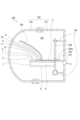
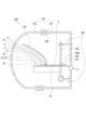
- FIG. 2 to 9 show a first embodiment of the present invention, and this figure is a cross-sectional view of a vehicle lamp in which a light source module is arranged.
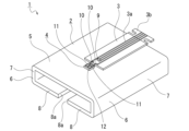
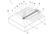
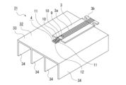
- FIG. 2 is a perspective view of a light source module.
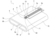
- 1 is a perspective view showing a light source module in which a first surface portion is formed into a curved shape;
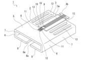
- FIG. 2 is a perspective view showing a light source module in which a slit is formed.
- 11 is a perspective view showing a light source module in which slits are formed in a heat sink formed from a block-shaped material.
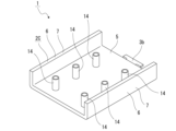
- FIG. FIG. 2 is a perspective view showing a light source module having a four-section folded heat sink.
- FIG. 11 is a perspective view showing a light source module provided with a heat dissipation protrusion formed by drawing;
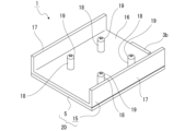
- FIG. 1 is a perspective view showing a light source module having a heat sink configured by attaching a heat dissipation plate to a base portion.
- FIG. 9 is a perspective view showing a light source module having a heat sink configured by attaching a heat dissipation plate to a base portion, as viewed from a different direction than in FIG. 8 .
- 11 to 22 show a second embodiment of the present invention, and this figure is a cross-sectional view of a vehicle lamp in which a light source module is arranged.
- FIG. 2 is a perspective view of a light source module.
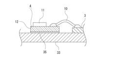
- FIG. 4 is a cross-sectional view showing a state in which a light emitter is joined to a heat sink.
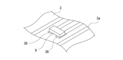
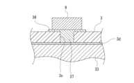
- FIG. FIG. 2 is a perspective view showing a state in which the thermistor is mounted on a wiring board. 4 is a cross-sectional view showing a state in which the thermistor is mounted on a wiring board.
- FIG. 13 is a perspective view showing another state in which the thermistor is mounted on the wiring board.
- FIG. 1 is a perspective view showing a light source module in which a joining recess is filled with a sintered bonding material and a light emitter is attached to a heat sink.
- FIG. 10 is a cross-sectional view showing a state in which a joining recess is filled with a sintered bonding material and a light-emitting body is attached to a heat sink.
- FIG. 11 is a perspective view showing a light source module in which a space is formed in a heat dissipation fin portion.
- FIG. 21 shows a light source module having a heat sink to which two heat sinks are coupled together with FIG. 20, and this figure is a perspective view showing a state in which the two heat sinks are separated.
- FIG. 2 is a perspective view showing a state in which two heat sinks are joined together.
- FIG. 23 shows a light source module having another heat sink to which two heat sinks are coupled together with FIG.
- FIG. 22 is a perspective view showing a state in which the two heat sinks are separated.
- FIG. 2 is a perspective view showing a state in which two heat sinks are joined together.
- 24 to 28 show a third embodiment of the present invention, and this figure is a perspective view of a light source module.
- FIG. 2 is a perspective view showing a state in which a reflector provided as an optical component is attached to the light source module.
- FIG. 2 is a perspective view showing a state in which a reflector integrated with a lens provided as an optical component is attached to the light source module.
- 13 is a plan view showing an example in which the recognition marks are formed at positions other than the left and right of the light-emitting body.
- FIG. FIG. 11 is a perspective view showing an example in which a resin sheet is attached to a heat sink.
- 1 is a perspective view showing an example in which a resin sheet including a mounting portion and a circuit forming portion is attached to a heat sink;
- the direction of light emitted from the light source module toward the outside is defined as the forward direction, and the directions of front, back, up, down, left and right are indicated. Note that the directions of front, back, up, down, left and right shown below are for the convenience of explanation, and the present invention is not limited to these directions when it comes to implementing the invention.
- the vehicle lamp 100 is, for example, a vehicle headlamp, and includes a lamp housing 101 with an opening at the front end and a cover 102 that closes the opening of the lamp housing 101 (see FIG. 1).
- the lamp housing 101 and the cover 102 form a lamp housing 103, and the space inside the lamp housing 103 is formed as a lamp chamber 104.
- a bracket 106 supported by an aiming mechanism 105 is disposed in the lamp chamber 104.
- the aiming mechanism 105 is supported at the rear end of the lamp housing 101 and has an adjusting screw, a pivot member, etc.
- An insertion hole 106a is formed in the bracket 106.
- a connecting member 107 is attached to the rear end of the lamp housing 101, and a connector 108 disposed in the lamp chamber 104 is connected to the connecting member 107 via a cable.
- a power supply circuit (not shown) is connected to the connecting member 107 via a cable. The power supply circuit is located outside the vehicle lamp 100.
- the light source module 1 is disposed in the lamp chamber 104 and is attached to a bracket 106.
- the light source module 1 is fitted with optical components 109 such as a reflector, a lens holder, and a reflector integrated with a lens.
- the wiring board 3 is formed as a rigid board with little flexibility, with the base material being resin or the like.
- the base material being resin or the like.
- glass epoxy or alumina ceramics
- a flexible printed wiring board with high flexibility may also be used as the wiring board 3.
- a power supply circuit 3a that supplies power to the light emitter 4 is formed on the upper surface of the wiring board 3.
- the rear end of the wiring board 3 is provided as a connection terminal portion 3b, which may be, for example, a card edge connector.
- a thermistor 9 is mounted on the front end of the wiring board 3.
- the wiring board 3 is attached to the center of the base 5 in the left-right direction by adhesive or the like, and the connection terminal 3b is in a state where it protrudes rearward from the base 5.
- the connection terminal 3b is inserted into the insertion hole 106a of the bracket 106 and connected to the connector 108 (see FIG. 1). Therefore, a current can be supplied from the power supply circuit to the power supply circuit 3a of the wiring board 3 via the connection member 107 and the connector 108.
- the light emitter 4 is attached to the front side of the wiring board 3 on the upper surface of the base portion 5 (see FIG. 2).
- the light emitter 4 is connected to the power supply circuit 3a by, for example, so-called wire bonding using a metal wire 10.
- the light source module 1 configured as described above, when the light source 11 is driven, heat is generated in the light emitter 4 and the wiring board 3, and the generated heat is transferred to the heat sink 2.
- the heat transferred to the heat sink 2 is released to the outside from the heat dissipation fin section 6 in addition to the base section 5, suppressing the temperature rise of the light source 11 and ensuring good light emission from the light source 11.
- the heat sink 2 is formed by bending the aluminum plate and the heat dissipation fin portion 6 is formed by bending it relative to the base portion 5, it is possible to miniaturize the heat sink 2 and ensure a sufficient heat dissipation area, thereby improving heat dissipation while ensuring compactness.
- a portion of the heat dissipation fin portion 6 is positioned inside the outer periphery of the base portion 5 while being separated from the base portion 5 in the thickness direction of the base portion 5.
- the heat dissipation fin section 6 is located inside the outer periphery of the base section 5, it is possible to increase the area of the heat dissipation fin section 6 without increasing the external shape of the heat sink 2, thereby improving heat dissipation without increasing the size of the light source module 1.
- the heat dissipation fin section 6 is composed of a first surface section 7 and a second surface section 8 formed by bending, a large heat dissipation area can be secured with a simple configuration, improving heat dissipation performance.
- the heat dissipation fin portion 6 of the heat sink 2 has a first surface portion 7 facing left and right, but the heat sink 2 may also be configured to have a heat dissipation fin portion 6A having an arc-shaped first surface portion 7A, for example (see Figure 3).
- the heat dissipation fin portion 6A can be formed by a single bending process, thereby shortening the manufacturing time of the light source module 1.
- stress concentration is less likely to occur in the continuous portion between the first surface portion 7A and the base portion 5 and in the heat dissipation fin portion 6A, which can improve the strength of the heat sink 2.
- the surface of the heat sink 2 may be subjected to a blasting process.
- Blasting is a surface processing process in which a large number of granular abrasives are collided with the workpiece to roughen the surface.
- the surface area of the heat sink 2 is increased, which in turn increases the heat dissipation area, thereby further improving heat dissipation.
- the surface of the heat sink 2 may be painted with a dark color such as black anodized aluminum. By painting the surface of the heat sink 2 dark, the thermal emissivity (emission rate) increases, and the heat dissipation performance can be further improved.
- a heat sink 2A made of a block-shaped material increases the thermal capacity, and the slits 13 increase the heat dissipation area and increase the air flow, improving heat dissipation.
- the heat sink 2B is composed of a base portion 5 and three or four first surfaces 7 formed by bending downward from the base portion 5.
- the first surfaces 7 are formed by bending from three portions of the left and right ends and the front and rear ends of the base portion 5, or by bending from four portions of the left and right ends and the front and rear ends of the base portion 5.
- the heat sink 2B may also be configured to have a second surface 8 that is continuous with each of the two first surfaces 7.
- a heat sink 2C having a base portion 5, a first surface portion 7, and a heat dissipation protrusion 14 may be used (see FIG. 7).
- the heat dissipation protrusion 14 is formed by drawing so as to protrude downward from the base portion 5, for example, into a cylindrical shape.
- multiple heat dissipation protrusions 14 are provided, and are positioned at a distance in the front, back, left and right directions.
- a heat sink 2D having a heat sink plate 15 attached to the base portion 5 may be used (see Figures 8 and 9).
- the base portion 5 has multiple screw holes (not shown), which are positioned, for example, at intervals in the front, back, left and right directions.
- the heat sink 15 is made up of a connecting surface portion 16 facing in the vertical direction, a pair of fin portions 17 protruding downward from both the left and right ends of the connecting surface portion 16, and a number of heat dissipation protrusions 18 protruding downward from the connecting surface portion 16.
- the heat dissipation protrusions 18 are formed by drawing and are, for example, cylindrical.
- multiple heat dissipation protrusions 18 are provided between the fin portions 17, and are positioned at a distance in the front, back, left and right directions.
- the land 36 to which the thermistor 9 is connected is connected to the heat transfer material 37 filled in the filling hole 3c, so that the thermal conductivity from the heat sink 32 to the thermistor 9 is increased, and the detection accuracy of the thermistor 9 can be improved.
- the heat sink 32 and the heat sink 32A may be joined to form the heat sink 40 (see Figures 19 and 20).
- Heat sink 32B is formed, for example, by extrusion molding of aluminum, and in addition to the upside-down structure of heat sink 32, has a rectangular block portion 41 and a pair of heat dissipation ends 43 at both left and right ends.
- Heat dissipation end 43 consists of a horizontal portion 43a that protrudes outward from the structure of heat sink 32 to the side, and a vertical portion 43b that protrudes downward from the outer end in the left-right direction of horizontal portion 43a.
- the structure of heat sink 32 in heat sink 32B may have, for example, two flow holes 44 that penetrate vertically and extend front-to-back. The formation of flow holes 44 forms a flow path through which air flows in the vertical direction, improving heat dissipation.
- heat sink 42 By using a heat sink 42 in which heat sink 32 and heat sink 32B are combined, the heat dissipation area is increased, ensuring higher heat dissipation performance.
- the heat sink 52 is formed, for example, by extrusion molding of aluminum, and is composed of a base portion 53 formed in the shape of a rectangular flat plate facing the vertical direction, and a number of heat dissipation fin portions 54 protruding downward from the base portion 53.
- the multiple heat dissipation fin portions 54 are formed, for example, in the shape of a plate extending in the front-rear direction, and are positioned at a distance from each other while facing the left-right direction.
- the positions of the two recognition marks 55 are detected by an automatic mounting machine, and the light emitter 4 is attached to the base portion 53 by adhesion or the like, based on the positional information of the detected two recognition marks 55.
- the optical component 109 is attached to the heat sink 52, the positions of the two recognition marks 55 are detected by the same automatic mounting machine, and the optical component 109 is attached to the base portion 53 by adhesion or the like, based on the positional information of the detected two recognition marks 55.
- the optical component 109 for example, a reflector that reflects the light emitted from the light source 11 is used (see FIG. 24).
- a reflector integrated with a lens 110 that functions as a lens holder may also be used as the optical component 109 (see FIG. 25).
- the optical component 109 is a reflector
- the vehicle lamp 100 becomes a so-called parabolic type that reflects light and irradiates it forward
- the optical component 109 is a reflector integrated with the lens 110
- the vehicle lamp 100 becomes a so-called PES (Projector Ellipsoid System) type that controls the light by the lens 110 and irradiates it forward.
- PES Projector Ellipsoid System
- the heat sink 52 is formed with a recognition mark 55 that serves as a reference for positioning, and the recognition mark 55 is used as a mark for positioning the light emitter 4 relative to the heat sink 52 and also as a mark for positioning the optical component 109 relative to the heat sink 52.
- the recognition mark 55 serves as a reference for the positioning of both the light emitter 4 and the optical component 109, it is possible to minimize the stacking tolerance regarding the position of the light emitter 4 and the optical component 109 relative to the heat sink 52, and the positional accuracy of the light emitter 4 and the optical component 109 relative to the heat sink 52 is high, thereby improving the light distribution performance of the light emitted from the light source 11.
- the recognition marks 55 are used as positioning holes for positioning the optical component 109, if the two recognition marks 55 are positioned directly to the side of the light emitter 4, there is a possibility that the light emitter 4 and the optical component 109 may interfere with each other depending on the shape of the optical component 109 and the mounting position of the optical component 109 relative to the heat sink 52. Therefore, in such a case, it is desirable to form the two recognition marks 55 at a position spaced rearward from the light emitter 4 (see FIG. 26).
- the resin sheet 56 is made of a material with low thermal conductivity and is formed, for example, in a vertically elongated rectangular shape (see FIG. 27).
- a pair of resin sheets 56 are provided, and are attached to the left and right sides of the light emitter 4 and wiring board 3 on the base portion 53.
- shallow recesses are formed at both the left and right ends of the base portion 53, and the resin sheet 56 is attached to the heat sink 52 with the resin sheet 56 disposed in the recesses.
- An insertion hole 56a is formed at the front end of the resin sheet 56, and the resin sheet 56 is attached to the heat sink 52 with the insertion hole 56a positioned directly above the recognition mark 55.
- the diameter of the insertion hole 56a is made larger than the diameter of the recognition mark 55, and its central axis is aligned with the central axis of the recognition mark 55. Therefore, the position of the recognition mark 55 is visible through the insertion hole 56a and can be recognized by an automatic mounting machine.
- the resin sheet 56 may be made of a transparent resin material. In this case, light passes through the resin sheet 56, making it possible to recognize the position of the recognition mark 55, and the insertion hole 56a does not need to be formed.
- the optical component 109 is positioned on the heat sink 52 based on the position information of the recognition mark 55 detected by the automatic mounting machine, and the pair of adhesive protrusions 109b are attached to the upper surface of the resin sheet 56 by adhesive.
- the transfer of heat from the light emitter 4 to the base portion 53 to the optical component 109 is suppressed by the resin sheet 56, so deformation of the optical component 109 due to heat can be prevented and high positional accuracy of the optical component 109 relative to the heat sink 52 can be ensured.
- an insertion hole 56a having a diameter larger than the diameter of the recognition mark 55 is formed at a position corresponding to the recognition mark 55 in the resin sheet 56.
- the recognition mark 55 can be recognized through the insertion hole 56a, which prevents the optical component 109 from being deformed by heat and ensures even higher positional accuracy of the optical component 109 relative to the heat sink 52.
- a single resin sheet 56A may be used instead of the pair of resin sheets 56 (see FIG. 28).
- the wiring board 3 is not attached to the heat sink 52, and a shallow recess is formed in the base portion 53 in which the resin sheet 56A is placed.
- the mounting portion 57 is formed to have the same size and shape as the resin sheet 56, and has an insertion hole 57a at the front end.
- the diameter of the insertion hole 57a is made larger than the diameter of the recognition mark 55, and the central axis is aligned with the central axis of the recognition mark 55.
- the circuit forming portion 58 has a power supply circuit 58a formed therein, which is the same as the power supply circuit 3a formed on the wiring board 3.
- the front edge of the circuit forming portion 58 is positioned rearward of the front edge of the mounting portion 57.
- the rear end of the circuit forming portion 58 is provided as a connection terminal portion 58b, similar to the connection terminal portion 3b.
- a resin sheet 56A is placed on the base portion 53 at a position avoiding the light emitter 4, and a circuit forming portion 58 is positioned behind the light emitter 4.
- the transfer of heat from the light emitter 4 to the base portion 53 to the optical component 109 is suppressed by the resin sheet 56A, so deformation of the optical component 109 due to heat can be prevented and high positional accuracy of the optical component 109 relative to the heat sink 52 can be ensured.
Landscapes
- Engineering & Computer Science (AREA)
- General Engineering & Computer Science (AREA)
- Physics & Mathematics (AREA)
- Microelectronics & Electronic Packaging (AREA)
- Optics & Photonics (AREA)
- Arrangement Of Elements, Cooling, Sealing, Or The Like Of Lighting Devices (AREA)
Abstract
光源モジュール(1)は、光源として発光ダイオードが用いられた発光体(4)と、発光体が取り付けられ発光体の駆動時に生じる熱を放出するヒートシンク(2)と、ヒートシンクに取り付けられ発光体に給電を行う給電回路(3a)が形成された配線基板(3)とを備え、ヒートシンクはアルミニウム板が折曲加工されることにより形成され、ヒートシンクには発光体及び配線基板が取り付けられたベース部(5)とベース部の少なくとも両端部にそれぞれ連続されベース部に対して折り曲げられた放熱フィン部(6)とが設けられた。
Description
本発明は、光源を有する発光体と発光体が取り付けられたヒートシンクとを備えた光源モジュールについての技術分野に関する。
車輌用灯具には、例えば、リフレクターやレンズホルダー等の光学部品に結合されて使用される光源モジュールを有し、光源モジュールの光源から出射された光が外部へ向けて照射されるものがある(例えば、特許文献1参照)。
このような車輌用灯具においては、光源の駆動時に発生する熱が放熱フィンを有するヒートシンクに伝達されて放出され、光源の駆動時に発生する熱の良好な放熱性が確保され、光源の適正な駆動状態が確保される。ヒートシンクはアルミニウム等の金属材料による押出成形によって形成される場合も多い。
ところで、近年、高い輝度(照度)を確保する等のために光束量を高めることが必要になる場合も多く、このような光源モジュールにおいては、光源の良好な駆動状態を確保するために一層高い放熱性が必要とされている。
一方、光源モジュールにおいて一層高い放熱性を確保するために、例えば、押出成形によって形成されるヒートシンクの放熱フィンを大きくすると、ヒートシンクの全体の大きさが大きくなり光源モジュールの大型化を来たすおそれがある。
そこで、本発明の光源モジュールは、小型化を確保した上で放熱性の向上を図ることを目的とする。
本発明に係る光源モジュールは、光源として発光ダイオードが用いられた発光体と、前記発光体が取り付けられ前記発光体の駆動時に生じる熱を放出するヒートシンクと、前記ヒートシンクに取り付けられ前記発光体に給電を行う給電回路が形成された配線基板とを備え、前記ヒートシンクはアルミニウム板が折曲加工されることにより形成され、前記ヒートシンクには前記発光体及び前記配線基板が取り付けられたベース部と前記ベース部の少なくとも両端部にそれぞれ連続され前記ベース部に対して折り曲げられた放熱フィン部とが設けられたものである。
これにより、板状のアルミニウムが折り曲げられてヒートシンクが形成されると共に放熱フィン部がベース部に対して折り曲げられることにより形成される。
本発明に係る別の光源モジュールは、光源として発光ダイオードが用いられた発光体と、前記発光体が取り付けられ前記発光体の駆動時に生じる熱を放出するヒートシンクと、前記ヒートシンクに取り付けられ前記発光体に給電を行う給電回路が形成された配線基板とを備え、前記発光体が前記ヒートシンクに焼結結合材によって接合されることにより取り付けられたものである。
これにより、光源の駆動時に発生する熱の多くが熱伝導性の高い焼結結合材からヒートシンクに伝達されヒートシンクからの放熱量が増加する。
本発明に係るまた別の光源モジュールは、光源として発光ダイオードが用いられた発光体と、前記発光体が取り付けられ前記発光体の駆動時に生じる熱を放出するヒートシンクとを備え、前記ヒートシンクに位置決めの基準にされる認識マークが形成され、前記認識マークが前記ヒートシンクに対する前記発光体の位置決め用のマークとして使用されると共に前記ヒートシンクに対する光学部品の位置決め用のマークとして使用されたものである。
これにより、光学部品と発光体が何れも認識マークを位置決めの基準としてヒートシンクに取り付けられる。
本発明によれば、板状のアルミニウムが折り曲げられてヒートシンクが形成されると共に放熱フィン部がベース部に対して折り曲げられることにより形成されるため、ヒートシンクの小型化及び十分な放熱面積を確保することが可能になり、小型化を確保した上で放熱性の向上を図ることができる。
以下に、本発明を実施するための形態について添付図面を参照して説明する。以下の説明においては、光源モジュールから出射される光の外部への照射方向を前方として前後上下左右の方向を示すものとする。尚、以下に示す前後上下左右の方向は説明の便宜上のものであり、本発明の実施に関しては、これらの方向に限定されることはない。
<車輌用灯具の概略構成>
まず、車輌用灯具の概略構成について説明する(図1参照)。
まず、車輌用灯具の概略構成について説明する(図1参照)。
車輌用灯具100は、例えば、車輌用前照灯であり、前端に開口を有するランプハウジング101とランプハウジング101の開口を閉塞するカバー102とを備えている(図1参照)。ランプハウジング101とカバー102によって灯具外筐103が構成され、灯具外筐103の内部の空間が灯室104として形成されている。
灯室104にはエイミング機構105に支持されたブラケット106が配置されている。エイミング機構105はランプハウジング101の後端部に支持され、アジャスティングスクリューやピボット部材等を有している。ブラケット106には挿通孔106aが形成されている。
ランプハウジング101の後端部には接続部材107が取り付けられ、接続部材107にはケーブルを介して灯室104に配置されたコネクター108が接続されている。接続部材107にはケーブルを介して図示しない電源回路が接続されている。電源回路は車輌用灯具100の外側に位置されている。
灯室104には光源モジュール1が配置され、光源モジュール1はブラケット106に取り付けられている。光源モジュール1にはリフレクターやレンズホルダー、レンズと一体化したリフレクター等の光学部品109が取り付けられている。
<第1の実施の形態>
以下に、第1の実施の形態に係る光源モジュール1について説明する(図1乃至図9参照)。
以下に、第1の実施の形態に係る光源モジュール1について説明する(図1乃至図9参照)。
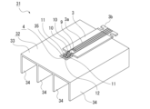
光源モジュール1は熱を放出するヒートシンク2とヒートシンク2に取り付けられた配線基板3とヒートシンク2に取り付けられた発光体4とを備えている(図2参照)。
ヒートシンク2は、例えば、アルミニウム板が折曲加工により所定の形状に折り曲げられて形成されている。ヒートシンク2は上下方向を向く矩形の平板状に形成されたベース部5とベース部5の左右両端部に連続された一対の放熱フィン部6とから成り、放熱フィン部6がベース部5に対して折り曲げられることにより形成されている。
放熱フィン部6はベース部5の左右両端部にそれぞれ連続された一対の第1の面部7と第1の面部7の下端部に連続された一対の第2の面部8とから成る。第1の面部7はベース部5に対して下方へ直角に折り曲げられ左右方向を向く状態にされている。第2の面部8は第1の面部7に対して互いに近付く方向へ直角に折り曲げられ上下方向を向く状態にされている。
従って、第2の面部8はベース部5の真下に位置され、ベース部5と厚み方向(上下方向)において離隔した状態でベース部5の左右両端より内側に位置されている。尚、第2の面部8はベース部5の真下に位置されていれば第1の面部7に対する折曲角度が90度に限られることはなく、第2の面部8の第1の面部7に対する折曲角度は、例えば、90度より大きくされていてもよい。
一対の第2の面部8は左右方向における先端縁8aが接した状態又は近接した状態にされていてもよい。第2の面部8の先端縁8aが接した状態又は近接した状態にされることにより、第2の面部8の表面積が大きくなり放熱フィン部6の全体の表面積が大きくなるため、放熱性の向上を図ることができる。
配線基板3は基材が樹脂等によって柔軟性に乏しいリジッド基板として形成されている。配線基板3の基材としては、例えば、ガラスエポキシやアルミナ(セラミックス)等が用いられている。但し、配線基板3として柔軟性の高いフレキシブルプリント配線板が用いられていてもよい。フレキシブルプリント配線板が用いられることにより、光源モジュール1の厚み(上下の幅)を薄くすることが可能である。
配線基板3の上面には発光体4に給電を行う給電回路3aが形成されている。配線基板3の後端部は接続端子部3bとして設けられ、接続端子部3bとしては、例えば、カードエッジコネクターが用いられている。配線基板3の前端部にはサーミスタ9が実装されている。
配線基板3はベース部5の左右方向における中央部に接着等によって取り付けられ、接続端子部3bがベース部5から後方に突出された状態にされている。接続端子部3bはブラケット106の挿通孔106aに挿通されコネクター108に接続されている(図1参照)。従って、電源回路から接続部材107とコネクター108を介して配線基板3の給電回路3aに電流の供給が可能な状態にされる。
発光体4はベース部5の上面において配線基板3の前側に取り付けられている(図2参照)。発光体4は、例えば、金属ワイヤー10による所謂ワイヤーボンディングによって給電回路3aに接続されている。
発光体4は光源11として発光ダイオード(LED:Light Emitting Diode)が用いられたLEDパッケージとして構成されている。発光体4はパッケージ基板12上に、例えば、二つの光源11が実装されて構成されている。光源11からは、例えば、近距離を照射するロービーム又は遠距離を照射するハイビームとしての光が出射される。
上記のように構成された光源モジュール1において、光源11の駆動時には発光体4や配線基板3に熱が生じ、発生した熱がヒートシンク2に伝達される。ヒートシンク2に伝達された熱はベース部5の他に放熱フィン部6から外部に放出され、光源11の温度上昇が抑制されて光源11からの光の良好な出射状態が確保される。
以上に記載した通り、光源モジュール1にあっては、ヒートシンク2としてアルミニウム板が用いられ、ヒートシンク2には発光体4及び配線基板3が取り付けられたベース部5とベース部5の両端部にそれぞれ連続されベース部5に対して折り曲げられた放熱フィン部6とが設けられている。
従って、板状のアルミニウムが折り曲げられてヒートシンク2が形成されると共に放熱フィン部6がベース部5に対して折り曲げられることにより形成されるため、ヒートシンク2の小型化及び十分な放熱面積を確保することが可能になり、小型化を確保した上で放熱性の向上を図ることができる。
また、放熱フィン部6の一部がベース部5の厚み方向においてベース部5と離隔した状態でベース部5の外周より内側に位置されている。
従って、ベース部5の外周より内側に放熱フィン部6の一部が存在するため、ヒートシンク2の外形状を大きくすることなく放熱フィン部6の面積を増加させることが可能になり、光源モジュール1の大型化を来すことなく放熱性の向上を図ることができる。
さらに、放熱フィン部6がベース部5の両端部に連続された第1の面部7と第1の面部7に連続された第2の面部8とから成り、第2の面部8がベース部5の厚み方向においてベース部5に対向する状態で位置されている。
従って、放熱フィン部6が折り曲げにより形成された第1の面部7と第2の面部8によって構成されるため、簡素な構成により大きな放熱面積を確保して放熱性の向上を図ることができる。
尚、上記には、ヒートシンク2の放熱フィン部6が左右方向を向く第1の面部7を有する構成にされた例を示したが、ヒートシンク2は、例えば、円弧面状の第1の面部7Aを有する放熱フィン部6Aが設けられた構成にされていてもよい(図3参照)。
ヒートシンク2が円弧面状の第1の面部7Aを有する構成にされる場合には、放熱フィン部6Aを1回の折曲加工により形成することが可能であるため、光源モジュール1の製造時間の短縮化を図ることができる。また、第1の面部7Aとベース部5の連続部分や放熱フィン部6Aに応力集中が生じ難くなり、ヒートシンク2の強度の向上を図ることもできる。
また、光源モジュール1においては、ヒートシンク2の表面にブラスト処理が施されていてもよい。ブラスト処理は、粒子状の無数の研磨材を被加工物に衝突させて表面の粗化等を行う表面加工処理である。
ヒートシンク2の表面にブラスト処理が施されることにより、ヒートシンク2の表面積が大きくなるため、放熱面積の増大による一層の放熱性の向上を図ることができる。
さらに、ヒートシンク2の表面に黒色のアルマイト等による暗色の塗装が施されていてもよい。ヒートシンク2の表面が暗色にされることにより、熱の放射率(放出率)が高まりより一層の放熱性の向上を図ることができる。
また、上記には、ヒートシンク2がアルミニウムによって形成された例を示したが、ヒートシンク2が、例えば、銅等のアルミニウムより熱伝導率の高い金属材料によって形成されていてもよい。但し、ヒートシンク2が銅によって形成される場合には、ヒートシンク2の表面を塗装して酸化防止処理を行う必要がある。この場合に、ヒートシンク2の表面に黒色等の暗色の塗装が施されることにより、熱の放射率が高まりより一層の放熱性の向上を図ることができる。
さらに、ヒートシンク2のベース部5には、例えば、前後方向に延びる一つ又は複数のスリット13が形成されていてもよい(図4参照)。ベース部5にスリット13が形成されることにより、ヒートシンク2の表面積が一層大きくなると共に空気の流動性が高くなるため、放熱面積の増大及び空気の流動性の向上によるより一層の放熱性の向上を図ることができる。尚、スリット13は放熱フィン部6や放熱フィン部6Aに形成されていてもよい。
また、光源モジュール1においては、板状の材料に代えて厚みの厚いブロック状の材料によって形成されたヒートシンク2Aが用いられてもよい(図5参照)。ヒートシンク2Aは放熱フィン部6を有さず厚みの厚いベース部5Aのみによって構成され、複数のスリット13を有している。
ブロック状の材料によって形成されたヒートシンク2Aが用いられることにより熱容量が高くなると共にスリット13によって放熱面積が大きくなると共に空気の流動性が高くなり、放熱性の向上を図ることができる。
さらに、上記には、左右両側の部分が折り曲げられたヒートシンク2の例を示したが、ヒートシンク2に代えて三つの部分又は四つの部分が折り曲げられたヒートシンク2Bが用いられてもよい(図6参照)。
ヒートシンク2Bはベース部5とベース部5に対して下方に折り曲げられて形成された三つ又は四つの第1の面部7とによって構成されている。第1の面部7は、ベース部5の左右両端部と前後両端部のうちの何れかの三つの部分に対して折り曲げられ、又は、ベース部5の左右両端部と前後両端部の四つの部分に対して折り曲げられて形成されている。
このような構成のヒートシンク2Bが用いられることにより、放熱面積を大きくすることが可能になり、光源モジュール1の小型化を確保した上で放熱性の向上を図ることができる。
尚、ヒートシンク2Bにおいても二つの第1の面部7にそれぞれ連続する第2の面部8を有する構成にされていてもよい。
さらにまた、ヒートシンク2に代えてベース部5と第1の面部7と放熱用突部14を有する構成のヒートシンク2Cが用いられてもよい(図7参照)。放熱用突部14は絞り加工によってベース部5から下方に突出された形状にされ、例えば、円筒状にされている。放熱用突部14は、例えば、複数が設けられ、前後左右に離隔して位置されている。
ヒートシンク2Cが用いられることにより、放熱用突部14の数や大きさを自由に設定して放熱面積を大きくすることが可能になり、光源モジュール1の小型化を確保した上で放熱性の向上を図ることができる。
また、ヒートシンク2に代えてベース部5に放熱板15が取り付けられたヒートシンク2Dが用いられてもよい(図8及び図9参照)。
ベース部5には複数の図示しない螺孔が形成され、螺孔は、例えば、前後左右に離隔して位置されている。
放熱板15は上下方向を向く結合面部16と結合面部16の左右両端部からそれぞれ下方に突出された一対のフィン部17と結合面部16から下方に突出された複数の放熱用突部18とから成る。放熱用突部18は絞り加工によって形成され、例えば、円筒状にされている。放熱用突部18はフィン部17間において、例えば、複数が設けられ、前後左右に離隔して位置されている。
放熱板15は放熱用突部18にそれぞれ挿通された金属製の取付ネジ19が螺孔に螺合されることによりベース部5に取り付けられる。放熱板15はベース部5に取り付けられた状態において結合面部16の上面がベース部5の下面に面接触された状態にされている。
このようなヒートシンク2Dが用いられることにより、放熱用突部18の数や大きさを自由に設定して放熱面積を大きくすることが可能になり、光源モジュール1の小型化を確保した上で放熱性の向上を図ることができる。また、ヒートシンク2Dにおいては、放熱用突部18に挿通された取付ネジ19も放熱部として機能するため、簡素な構成により放熱性の一層の向上を図ることができる。
<第2の実施の形態>
次に、第2の実施の形態に係る光源モジュール31について説明する(図10乃至図22参照)。
次に、第2の実施の形態に係る光源モジュール31について説明する(図10乃至図22参照)。
光源モジュール31は光源モジュール1に代えて車輌用灯具100における灯室104に配置され、ブラケット106に取り付けられている(図10参照)。光源モジュール31にはリフレクターやレンズホルダー、レンズと一体化したリフレクター等の光学部品109が取り付けられている。
光源モジュール31は熱を放出するヒートシンク32とヒートシンク32に取り付けられた配線基板3とヒートシンク32に取り付けられた発光体4とを備えている(図11参照)。
ヒートシンク32は、例えば、アルミニウムの押出成形によって形成され、上下方向を向く矩形の平板状に形成されたベース部33とベース部33から下方に突出された複数の放熱フィン部34とから成る。複数の放熱フィン部34は、例えば、前後方向に延びる板状に形成され、左右方向を向いた状態で左右に離隔して位置されている。
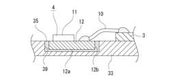
発光体4はベース部33に焼結結合材35によって接合されて取り付けられている(図12参照)。焼結結合材35としては、例えば、銀ナノペーストが使用されている。尚、一般に、発光体を接合するために用いられる放熱性の高い接着剤の熱伝導率は5~10W/m・Kであるが、銀ナノペーストの熱伝導率は約200W/m・Kであり非常に高い。
配線基板3に実装されたサーミスタ9は配線基板3の二つのランド36上に接合されている(図13及び図14参照)。サーミスタ9は温度検出用の素子であり、光源モジュール31の温度、特に、ヒートシンク32の温度を検出する機能を有している。サーミスタ9によって検出された温度情報は図示しない制御回路に入力され、制御回路が入力された温度情報に基づいて発光体4に対する電流値の制御を行うことが可能にされている。
配線基板3にはランド36の真下に充填孔3cが形成され、充填孔3cには銅等の金属材料によって形成された伝熱材37が充填されている。配線基板3の下面にはレジスト層3dが形成されている。伝熱材37は上面がランド36に接続され下面がレジスト層3dに接した状態にされている。従って、伝熱材37がヒートシンク32のベース部33に近付いた状態にされている。伝熱材37の下面がレジスト層3dに接しベース部33に接しない状態にされることにより、短絡の発生が防止されている。尚、伝熱材37とランド36は同じ材料によって一体に形成されていてもよい。
このように光源モジュール31にあっては、配線基板3に伝熱材37が充填された充填孔3cが形成され、配線基板3に形成されサーミスタ9が接続されたランド36が伝熱材37に接続されている。
従って、サーミスタ9が接続されたランド36が充填孔3cに充填された伝熱材37に接続されるため、サーミスタ9に対するヒートシンク32からの熱伝導性が高くなり、サーミスタ9の検出精度の向上を図ることができる。
尚、サーミスタ9はランド36に接合されず、ランド36に金属ワイヤー38によるワイヤーボンディングによって接続されていてもよい(図15参照)。この場合にサーミスタ9は焼結結合材35、例えば、銀ナノペーストによって配線基板3に接合される。
このようにサーミスタ9が配線基板3に焼結結合材35によって接合されランド36にワイヤーボンディングにより接続されることにより、発光体4がヒートシンク32に焼結結合材35によって接合されると共にサーミスタ9が配線基板3に焼結結合材35によって接合されるため、発光体4とサーミスタ9の接合において半田印刷やリフロー等の工程を必要とせず、光源モジュール31の製造コストの低減及び製造時間の短縮化を図ることができる。尚、サーミスタ9の接合は焼結結合材35の代わりに、放熱性の高い接着剤を使用してもよい。
上記のように構成された光源モジュール31において、光源11の駆動時には発光体4や配線基板3に熱が生じ、発生した熱がヒートシンク32に伝達される。ヒートシンク32に伝達された熱はベース部33の他に放熱フィン部34から外部に放出され、光源11の温度上昇が抑制されて光源11からの光の良好な出射状態が確保される。
以上に記載した通り、光源モジュール31にあっては、発光体4がヒートシンク32に焼結結合材35によって接合されることにより取り付けられている。
従って、光源11の駆動時に発生する熱の多くが熱伝導性の高い焼結結合材35からヒートシンク32に伝達されヒートシンク32からの放熱量が増加するため、ヒートシンク32の大型化を来すことなくヒートシンク32からの放熱量を増やすことが可能になり、光源モジュール31の小型化を確保した上で放熱性の向上を図ることができる。
また、焼結結合材35として銀ナノペーストが用いられることにより、発光体4が焼結結合材35の中でも特に高い熱伝導率を有する銀ナノペーストによってヒートシンク32に接合されるため、光源11の駆動時に発生する熱の発光体4からヒートシンク32への伝達量が増加し、一層の放熱性の向上を図ることができる。
上記には、ヒートシンク32のベース部33が平板状に形成された例を示したが、ベース部33には上方に開口された接合用凹部39が形成され、接合用凹部39に焼結結合材35が充填されていてもよい(図16及び図17参照)。接合用凹部39の外形は発光体4の外形より大きくされ、発光体4におけるパッケージ基板12の底面12aの全体と外周面12bの少なくとも一部とに焼結結合材35が付着される。
このような構成にされることにより、接合用凹部39に充填された焼結結合材35がパッケージ基板12の外周面12bに付着された状態で発光体4がヒートシンク32に取り付けられるため、光源11の駆動時に発生する熱の発光体4からヒートシンク32への伝達量が増加し、より一層の放熱性の向上を図ることができる。
また、焼結結合材35の発光体4に対する付着面積(密着面積)が大きくなり、発光体4のヒートシンク32に対する接合強度の向上を図ることができる。
尚、接合用凹部39に発光体4が配置され焼結結合材35が充填される構成の場合には、放熱性の向上及び接合強度の向上を図ることができるため、焼結結合材35に代えて一般的に使用される放熱性の高い接着剤が用いられてもよい。
上記には、ヒートシンク32の放熱フィン部34が前後方向に延びる板状に形成された例を示したが、光源モジュール31においては、放熱フィン部34が前後に離隔した複数の突片34aによって形成されていてもよい(図18参照)。放熱フィン部34がこのような構成にされることにより、前後方向において隣り合う突片34a間に空気の流動が行われる空間34bが形成される。
従って、左右方向において隣り合う放熱フィン部34間に空気の前後方向への流動が行われる流路が形成されると共に前後方向において隣り合う突片34a間に空気の左右方向への流動が行われる空間34bが形成され、空気の高い流動状態が得られヒートシンク32の高い放熱性を確保することができる。
さらに、光源モジュール31においては、複数のヒートシンクが結合された放熱体として設けられていてもよい(図19乃至図22参照)。
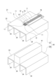
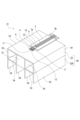
例えば、ヒートシンク32とヒートシンク32Aが結合されることにより放熱体40が構成されてもよい(図19及び図20参照)。
ヒートシンク32Aは、例えば、アルミニウムの押出成形によって形成され、ヒートシンク32の構造に加えて直方体状のブロック部41が設けられている。ブロック部41はベース部33の左右方向における中央部に位置されている。
ヒートシンク32Aはヒートシンク32に下方から結合され、ブロック部41がヒートシンク32の二つの放熱フィン部34間に嵌合される。ブロック部41は上面がヒートシンク32のベース部33に面接触され左右両面がそれぞれヒートシンク32の放熱フィン部34に面接触される。放熱体40はヒートシンク32に対して上下の大きさが大きくされるが左右の大きさは同じにされている。
ヒートシンク32とヒートシンク32Aが結合された放熱体40が用いられることにより、放熱面積が大きくなり、より高い放熱性を確保することができる。
このような構成にされることにより、例えば、より高い放熱性を必要とする高光束仕様の発光体4が用いられる場合にはヒートシンク32とヒートシンク32Aが結合された放熱体40を有する構成を使用して高い放熱性を確保し、高光束仕様以外の発光体4が用いられる場合にはヒートシンク32を有しヒートシンク32Aが結合されない構成を使用して十分な放熱性を確保することが可能である。
従って、高光束仕様の発光体4が用いられる場合と高光束仕様以外の発光体4が用いられる場合とにおいて、それぞれで異なるヒートシンクを設計する必要がなく、何れの場合においてもヒートシンク32を共用化することができ、光源モジュール31の製造コストの低減を図ることができる。
また、ヒートシンク32とヒートシンク32Bが結合されることにより放熱体42が構成されてもよい(図21及び図22参照)。
ヒートシンク32Bは、例えば、アルミニウムの押出成形によって形成され、ヒートシンク32の上下が反転した構造に加えて直方体状のブロック部41と左右両端部として一対の放熱端部43が設けられている。放熱端部43はヒートシンク32の構造から側方における外方に突出された水平部43aと水平部43aの左右方向における外側の端部から下方に突出された垂直部43bとから成る。尚、ヒートシンク32Bにおけるヒートシンク32の構造には上下に貫通され前後に延びる、例えば、二つの流動孔44が形成されていてもよい。流動孔44が形成されることにより、空気の上下方向への流動が行われる流路が形成され、放熱性の向上が図られる。
ヒートシンク32Bはヒートシンク32に下方から結合され、ブロック部41がヒートシンク32の二つの放熱フィン部34間に嵌合され、ヒートシンク32の各放熱フィン部34がヒートシンク32Bの各放熱フィン部34に隣り合って位置されると共に放熱端部43が左右方向においてヒートシンク32の外側に位置される。ブロック部41は上面がヒートシンク32のベース部33に面接触され左右両面がそれぞれヒートシンク32の放熱フィン部34に面接触される。放熱体42はヒートシンク32に対して左右の大きさが大きくされるが上下の大きさは略同じにされている。
ヒートシンク32とヒートシンク32Bが結合された放熱体42が用いられることにより、放熱面積が大きくなり、より高い放熱性を確保することができる。
このような構成にされることにより、例えば、より高い放熱性を必要とする高光束仕様の発光体4が用いられる場合にはヒートシンク32とヒートシンク32Bが結合された放熱体42を有する構成を使用して高い放熱性を確保し、高光束仕様以外の発光体4が用いられる場合にはヒートシンク32を有しヒートシンク32Bが結合されない構成を使用して十分な放熱性を確保することが可能である。
従って、高光束仕様の発光体4が用いられる場合と高光束仕様以外の発光体4が用いられる場合とにおいて、それぞれで異なるヒートシンクを設計する必要がなく、何れの場合においてもヒートシンク32を共用化することができ、光源モジュール31の製造コストの低減を図ることができる。
尚、上記したヒートシンク32、ヒートシンク32A、ヒートシンク32Bのベース部33には、例えば、前後方向に延びる一つ又は複数の図示しないスリットが形成されていてもよい。ベース部33にスリットが形成されることにより、ヒートシンク32の表面積が一層大きくなると共に空気の流路が形成されるため、放熱面積の増大及び空気の流動性の向上によるより一層の放熱性の向上を図ることができる。但し、スリットは放熱フィン部34に形成されていてもよい。
<第3の実施の形態>
次に、第3の実施の形態に係る光源モジュール51について説明する(図10、図23乃至図28参照)。
次に、第3の実施の形態に係る光源モジュール51について説明する(図10、図23乃至図28参照)。
光源モジュール51は光源モジュール1に代えて車輌用灯具100における灯室104に配置され、ブラケット106に取り付けられている(図10参照)。光源モジュール51にはリフレクターやレンズホルダー、レンズと一体化したリフレクター等の光学部品109が取り付けられている。
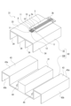
光源モジュール51は熱を放出するヒートシンク52とヒートシンク52に取り付けられた配線基板3とヒートシンク52に取り付けられた発光体4とを備えている(図23参照)。
ヒートシンク52は、例えば、アルミニウムの押出成形によって形成され、上下方向を向く矩形の平板状に形成されたベース部53とベース部53から下方に突出された複数の放熱フィン部54とから成る。複数の放熱フィン部54は、例えば、前後方向に延びる板状に形成され、左右方向を向いた状態で左右に離隔して位置されている。
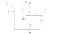
ヒートシンク52のベース部53には、例えば、発光体4の左右にそれぞれ認識マーク55が形成されている。認識マーク55はベース部53上に付された印であってもよく孔(認識孔)であってもよい。認識マーク55はヒートシンク52に発光体4が取り付けられるときの位置決め用のマークとして使用されると共にヒートシンク52に光学部品109が取り付けられるときの位置決め用のマークとして使用される。
従って、ヒートシンク52に発光体4が取り付けられるときには、自動搭載機によって二つの認識マーク55の位置が検出され検出された二つの認識マーク55の位置情報を基準にして発光体4がベース部53に接着等によって取り付けられる。また、ヒートシンク52に光学部品109が取り付けられるときには、同じ自動搭載機によって二つの認識マーク55の位置が検出され検出された二つの認識マーク55の位置情報を基準にして光学部品109がベース部53に接着等によって取り付けられる。
尚、光学部品109には本体109aの下端部から後方に突出された一対の接着用突部109bが左右に離隔して設けられており、光学部品109は一対の接着用突部109bがベース部53における配線基板3の左右の位置に接着によって取り付けられる(図24参照)。
また、光学部品109としては、例えば、光源11から出射された光を反射するリフレクターが用いられている(図24参照)。但し、光学部品109としてレンズホルダーとしての機能を有するレンズ110と一体化したリフレクターが用いられていてもよい(図25参照)。光学部品109がリフレクターの場合には、車輌用灯具100が光を反射して前方へ向けて照射する所謂パラボラ型になり、光学部品109がレンズ110と一体化したリフレクターの場合には、車輌用灯具100が光をレンズ110によって制御して前方へ向けて照射する所謂PES(Projector Ellipsoid System)型になる。
上記のように構成された光源モジュール51において、光源11の駆動時には発光体4や配線基板3に熱が生じ、発生した熱がヒートシンク52に伝達される。ヒートシンク52に伝達された熱はベース部53の他に放熱フィン部54から外部に放出され、光源11の温度上昇が抑制されて光源11からの光の良好な出射状態が確保される。
ところで、光源モジュールは、特許文献1に示されるように、リフレクターやレンズホルダー等の光学部品に結合されて使用されるが、ヒートシンクに対する光学部品の取付位置とヒートシンクに対する発光体の取付位置とは光源から出射される光の制御状態に影響を及ぼすため、光学部品と発光体のヒートシンクに対する取付精度を高める必要がある。
以上に記載した通り、光源モジュール51にあっては、ヒートシンク52に位置決めの基準にされる認識マーク55が形成され、認識マーク55がヒートシンク52に対する発光体4の位置決め用のマークとして使用されると共にヒートシンク52に対する光学部品109の位置決め用のマークとして使用されている。
従って、発光体4と光学部品109が何れも認識マーク55を位置決めの基準としてヒートシンク52に取り付けられるため、発光体4と光学部品109のヒートシンク52に対する取付を同一の設備(自動搭載機)によって行うことが可能になり、発光体4と光学部品109のヒートシンク52に対する取付精度の向上を図ることができる。
また、認識マーク55が発光体4と光学部品109の双方の位置決めの基準にされるため、ヒートシンク52に対する発光体4と光学部品109の位置に関する積み上げの公差を最小限にすることが可能になり、ヒートシンク52に対する発光体4と光学部品109の位置精度が高く光源11から出射される光に関する配光性能の向上を図ることができる。
さらに、光学部品109を取り付けるための位置決め孔をヒートシンク52に形成する必要がないと共に光学部品109に位置決めピンを形成する必要がないため、製造コストの低減を図ることができる。
さらにまた、認識マーク55として認識孔が形成される場合には、ヒートシンク52に孔を形成することにより認識マーク55が形成されるため、認識マーク55を容易に形成することが可能であり、製造コストの一層の低減を図った上でヒートシンク52に対する発光体4と光学部品109の取付精度の向上を図ることができる。
尚、認識マーク55が認識孔の場合には、認識マーク55が光学部品109を位置決めするための位置決め孔として用いられていてもよい。この場合には光学部品109に認識マーク55に挿入される位置決めピンが設けられる。
また、認識マーク55が光学部品109を位置決めするための位置決め孔として用いられる場合において、二つの認識マーク55が発光体4の真横に位置されると、光学部品109の形状や光学部品109のヒートシンク52に対する取付位置によっては発光体4と光学部品109が干渉する可能性がある。従って、このような場合には二つの認識マーク55が発光体4から後方に離隔した位置に形成されることが望ましい(図26参照)。
以下に、光学部品109が樹脂シート56を介してヒートシンク52に取り付けられる構成の例について説明する(図27及び図28参照)。
樹脂シート56は熱伝導性の低い材料によって、例えば、縦長の矩形状に形成されている(図27参照)。樹脂シート56は一対が設けられ、ベース部53における発光体4と配線基板3の左右にそれぞれ取り付けられている。樹脂シート56が用いられる場合には、ベース部53の左右両端部に浅い凹部が形成され、樹脂シート56が凹部に配置された状態でヒートシンク52に取り付けられる。ベース部53に凹部が形成されることにより、光源モジュール51の上下方向における大型化を抑制することができる。
樹脂シート56の前端部には挿入孔56aが形成され、樹脂シート56は挿入孔56aが認識マーク55の真上に位置された状態でヒートシンク52に取り付けられている。挿入孔56aの径は認識マーク55の径より大きくされており、中心軸が認識マーク55の中心軸に一致されている。従って、認識マーク55の位置は挿入孔56aを介して視認可能にされており自動搭載機によって認識可能にされている。
尚、樹脂シート56は透明な樹脂材料によって形成されていてもよく、この場合には樹脂シート56を光が透過されて認識マーク55の位置が認識可能になり、挿入孔56aが形成されていなくてもよい。
光学部品109は自動搭載機によって検出された認識マーク55の位置情報を基準にしてヒートシンク52に位置決めされ、一対の接着用突部109bがそれぞれ樹脂シート56の上面に接着によって取り付けられる。
このようにベース部53には少なくとも発光体4を回避した位置に樹脂シート56が配置され、光学部品109が樹脂シート56を介してベース部53に取り付けられる。
従って、光源11の駆動時に発光体4からベース部53に伝達される熱の光学部品109への伝達が樹脂シート56によって抑制されるため、光学部品109の熱による変形を防止してヒートシンク52に対する光学部品109の高い位置精度を確保することができる。
また、光学部品109の耐熱性を考慮して光源11から出射される光の強度を低下させる必要がなく、配光設計における自由度の向上を図ることができる。
さらに、樹脂シート56における認識マーク55に対応する位置に認識マーク55の径より大きい径を有する挿入孔56aが形成されている。
従って、挿入孔56aを介して認識マーク55の認識が可能になるため、光学部品109の熱による変形を防止した上でヒートシンク52に対する光学部品109の一層高い位置精度を確保することができる。
また、光源モジュール51においては、一対の樹脂シート56に代えて一つの樹脂シート56Aが用いられていてもよい(図28参照)。樹脂シート56Aが用いられる場合には、ヒートシンク52に配線基板3が取り付けられておらず、ベース部53に樹脂シート56Aが配置される浅い凹部が形成されている。
樹脂シート56Aは熱伝導性の低い材料によって形成され、左右両側にそれぞれ位置された一対の取付部57と一対の取付部57間に位置された回路形成部58とが一体に形成されて成る。
取付部57は樹脂シート56と同じ大きさ及び形状に形成され、前端部に挿入孔57aを有している。挿入孔57aの径は認識マーク55の径より大きくされており、中心軸が認識マーク55の中心軸に一致される。
回路形成部58には配線基板3に形成された給電回路3aと同じ給電回路58aが形成されている。回路形成部58は前縁が取付部57の前縁より後側に位置されている。回路形成部58の後端部は接続端子部3bと同様に接続端子部58bとして設けられている。
ベース部53には発光体4を回避した位置に樹脂シート56Aが配置され、発光体4の後側に回路形成部58が位置される。
光学部品109は自動搭載機によって検出された認識マーク55の位置情報を基準にしてヒートシンク52に位置決めされ、一対の接着用突部109bがそれぞれ樹脂シート56Aにおける取付部57の上面に接着によって取り付けられる。
上記のようにベース部53には発光体4を回避した位置に樹脂シート56Aが配置され、光学部品109が樹脂シート56Aを介してベース部53に取り付けられる。
従って、光源11の駆動時に発光体4からベース部53に伝達される熱の光学部品109への伝達が樹脂シート56Aによって抑制されるため、光学部品109の熱による変形を防止してヒートシンク52に対する光学部品109の高い位置精度を確保することができる。
また、光学部品109の耐熱性を考慮して光源11から出射される光の強度を低下させる必要がなく、配光設計における自由度の向上を図ることができる。
さらに、樹脂シート56Aにおける認識マーク55に対応する位置に認識マーク55の径より大きい径を有する挿入孔57aが形成されている。
従って、挿入孔57aを介して認識マーク55の認識が可能になるため、光学部品109の熱による変形を防止した上でヒートシンク52に対する光学部品109の一層高い位置精度を確保することができる。
さらにまた、樹脂シート56Aには発光体4に給電を行う給電回路58aが形成されている。
従って、樹脂シート56Aの一部が配線基板として設けられるため、専用の配線基板を用いる必要がなく、部品点数の削減を図った上で光学部品109の熱による変形を防止してヒートシンク52に対する光学部品109の高い位置精度を確保することができる。
尚、樹脂シート56Aは透明な樹脂材料によって形成されていてもよく、この場合には樹脂シート56Aを光が透過されて認識マーク55の位置が認識可能になり、挿入孔57aが形成されていなくてもよい。
1 光源モジュール
2 ヒートシンク
3 配線基板
3a 給電回路
4 発光体
5 ベース部
6 放熱フィン部
7 第1の面部
8 第2の面部
9 サーミスタ
10 金属ワイヤー
11 光源
12 パッケージ基板
6A 放熱フィン部
7A 第1の面部
13 スリット
2A ヒートシンク
5A ベース部
2B ヒートシンク
2C ヒートシンク
2D ヒートシンク
31 光源モジュール
32 ヒートシンク
33 ベース部
34 放熱フィン部
35 焼結結合材
36 ランド
37 伝熱材
3c 充填孔
38 金属ワイヤー
39 接合用凹部
12b 外周面
34a 突片
34b 空間
32A ヒートシンク
32B ヒートシンク
51 光源モジュール
52 ヒートシンク
53 ベース部
55 認識マーク
56 樹脂シート
56a 挿入孔
56A 樹脂シート
57a 挿入孔
58a 給電回路
2 ヒートシンク
3 配線基板
3a 給電回路
4 発光体
5 ベース部
6 放熱フィン部
7 第1の面部
8 第2の面部
9 サーミスタ
10 金属ワイヤー
11 光源
12 パッケージ基板
6A 放熱フィン部
7A 第1の面部
13 スリット
2A ヒートシンク
5A ベース部
2B ヒートシンク
2C ヒートシンク
2D ヒートシンク
31 光源モジュール
32 ヒートシンク
33 ベース部
34 放熱フィン部
35 焼結結合材
36 ランド
37 伝熱材
3c 充填孔
38 金属ワイヤー
39 接合用凹部
12b 外周面
34a 突片
34b 空間
32A ヒートシンク
32B ヒートシンク
51 光源モジュール
52 ヒートシンク
53 ベース部
55 認識マーク
56 樹脂シート
56a 挿入孔
56A 樹脂シート
57a 挿入孔
58a 給電回路
Claims (15)
- 光源として発光ダイオードが用いられた発光体と、
前記発光体が取り付けられ前記発光体の駆動時に生じる熱を放出するヒートシンクと、
前記ヒートシンクに取り付けられ前記発光体に給電を行う給電回路が形成された配線基板とを備え、
前記ヒートシンクはアルミニウム板が折曲加工されることにより形成され、
前記ヒートシンクには前記発光体及び前記配線基板が取り付けられたベース部と前記ベース部の少なくとも両端部にそれぞれ連続され前記ベース部に対して折り曲げられた放熱フィン部とが設けられた
光源モジュール。 - 前記放熱フィン部の一部が前記ベース部の厚み方向において前記ベース部と離隔した状態で前記ベース部の外周より内側に位置された
請求項1に記載の光源モジュール。 - 前記放熱フィン部が前記ベース部の両端部に連続された第1の面部と前記第1の面部に連続された第2の面部とから成り、
前記第2の面部が前記ベース部の厚み方向において前記ベース部に対向する状態で位置された
請求項2に記載の光源モジュール。 - 前記ヒートシンクの表面にブラスト処理が施された
請求項1、請求項2又は請求項3に記載の光源モジュール。 - 前記ベース部にスリットが形成された
請求項1、請求項2又は請求項3に記載の光源モジュール。 - 光源として発光ダイオードが用いられた発光体と、
前記発光体が取り付けられ前記発光体の駆動時に生じる熱を放出するヒートシンクと、
前記ヒートシンクに取り付けられ前記発光体に給電を行う給電回路が形成された配線基板とを備え、
前記発光体が前記ヒートシンクに焼結結合材によって接合されることにより取り付けられた
光源モジュール。 - 前記焼結結合材として銀ナノペーストが用いられた
請求項6に記載の光源モジュール。 - 前記発光体は前記発光ダイオードが実装されたパッケージ基板を有し、
前記ヒートシンクに前記焼結結合材が充填される接合用凹部が形成され、
前記発光体が前記接合用凹部に配置され、
前記焼結結合材が前記パッケージ基板における外周面の少なくとも一部に付着された
請求項6又は請求項7に記載の光源モジュール。 - 前記配線基板に温度検出用のサーミスタが前記焼結結合材によって接合され、
前記サーミスタが前記配線基板に形成されたランドにワイヤーボンディングにより接続された
請求項6又は請求項7に記載の光源モジュール。 - 前記配線基板に形成されたランドに温度検出用のサーミスタが接合され、
前記配線基板に充填孔が形成され、
前記充填孔には前記ランドに接続された伝熱材が充填された
請求項6又は請求項7に記載の光源モジュール。 - 光源として発光ダイオードが用いられた発光体と、
前記発光体が取り付けられ前記発光体の駆動時に生じる熱を放出するヒートシンクとを備え、
前記ヒートシンクに位置決めの基準にされる認識マークが形成され、
前記認識マークが前記ヒートシンクに対する前記発光体の位置決め用のマークとして使用されると共に前記ヒートシンクに対する光学部品の位置決め用のマークとして使用された
光源モジュール。 - 前記認識マークとして認識孔が形成された
請求項11に記載の光源モジュール。 - 前記ヒートシンクには前記発光体が取り付けられたベース部が設けられ、
前記ベース部には少なくとも前記発光体を回避した位置に樹脂シートが配置され、
前記光学部品が前記樹脂シートを介して前記ベース部に取り付けられる
請求項11又は請求項12に記載の光源モジュール。 - 前記樹脂シートにおける前記認識マークに対応する位置に前記認識マークの径より大きい径を有する挿入孔が形成された
請求項13に記載の光源モジュール。 - 前記樹脂シートには前記発光体に給電を行う給電回路が形成された
請求項13に記載の光源モジュール。
Priority Applications (1)
| Application Number | Priority Date | Filing Date | Title |
|---|---|---|---|
| JP2025530121A JPWO2025005047A1 (ja) | 2023-06-27 | 2024-06-24 |
Applications Claiming Priority (6)
| Application Number | Priority Date | Filing Date | Title |
|---|---|---|---|
| JP2023-105404 | 2023-06-27 | ||
| JP2023-105403 | 2023-06-27 | ||
| JP2023-105405 | 2023-06-27 | ||
| JP2023105403 | 2023-06-27 | ||
| JP2023105405 | 2023-06-27 | ||
| JP2023105404 | 2023-06-27 |
Publications (1)
| Publication Number | Publication Date |
|---|---|
| WO2025005047A1 true WO2025005047A1 (ja) | 2025-01-02 |
Family
ID=93939105
Family Applications (1)
| Application Number | Title | Priority Date | Filing Date |
|---|---|---|---|
| PCT/JP2024/022839 Ceased WO2025005047A1 (ja) | 2023-06-27 | 2024-06-24 | 光源モジュール |
Country Status (2)
| Country | Link |
|---|---|
| JP (1) | JPWO2025005047A1 (ja) |
| WO (1) | WO2025005047A1 (ja) |
Citations (5)
| Publication number | Priority date | Publication date | Assignee | Title |
|---|---|---|---|---|
| JP2010165464A (ja) * | 2009-01-13 | 2010-07-29 | Nikon Corp | 光源装置の製造方法および光源装置 |
| JP2014209502A (ja) * | 2013-03-29 | 2014-11-06 | 株式会社神戸製鋼所 | 車載led照明ヒートシンク用プレコートアルミニウム板材 |
| WO2017110031A1 (ja) * | 2015-12-24 | 2017-06-29 | パナソニックIpマネジメント株式会社 | 発光素子および照明装置 |
| JP2020038830A (ja) * | 2018-09-04 | 2020-03-12 | ヒュンダイ・モービス・カンパニー・リミテッド | 車両用ledランプ装置 |
| JP2022074954A (ja) * | 2020-11-05 | 2022-05-18 | 株式会社小糸製作所 | 光源ユニット |
-
2024
- 2024-06-24 JP JP2025530121A patent/JPWO2025005047A1/ja active Pending
- 2024-06-24 WO PCT/JP2024/022839 patent/WO2025005047A1/ja not_active Ceased
Patent Citations (5)
| Publication number | Priority date | Publication date | Assignee | Title |
|---|---|---|---|---|
| JP2010165464A (ja) * | 2009-01-13 | 2010-07-29 | Nikon Corp | 光源装置の製造方法および光源装置 |
| JP2014209502A (ja) * | 2013-03-29 | 2014-11-06 | 株式会社神戸製鋼所 | 車載led照明ヒートシンク用プレコートアルミニウム板材 |
| WO2017110031A1 (ja) * | 2015-12-24 | 2017-06-29 | パナソニックIpマネジメント株式会社 | 発光素子および照明装置 |
| JP2020038830A (ja) * | 2018-09-04 | 2020-03-12 | ヒュンダイ・モービス・カンパニー・リミテッド | 車両用ledランプ装置 |
| JP2022074954A (ja) * | 2020-11-05 | 2022-05-18 | 株式会社小糸製作所 | 光源ユニット |
Also Published As
| Publication number | Publication date |
|---|---|
| JPWO2025005047A1 (ja) | 2025-01-02 |
Similar Documents
| Publication | Publication Date | Title |
|---|---|---|
| KR100901401B1 (ko) | 광원 모듈 및 차량용 등기구 | |
| JP4662361B2 (ja) | 光源モジュール | |
| US10634329B2 (en) | Lamp unit and manufacturing method thereof | |
| JP4258321B2 (ja) | 車両用灯具 | |
| CN109424916B (zh) | 灯具单元以及车辆用灯具 | |
| JP5280087B2 (ja) | 少なくとも1つの発光ダイオードを支持する装備された可撓性電子支持体およびその製造方法 | |
| CN109556074B (zh) | 灯具单元以及车辆用灯具 | |
| US20070201233A1 (en) | Illumination Device | |
| WO2019176869A1 (ja) | 光源ユニット、及びこれに用いられる搭載部材の製造方法 | |
| JP4605789B2 (ja) | 発光モジュール及び車輌用灯具 | |
| JP5407025B2 (ja) | 車両用灯具の半導体型光源の光源ユニット、車両用灯具 | |
| WO2025005047A1 (ja) | 光源モジュール | |
| JP5073617B2 (ja) | 車両用灯具 | |
| US10571089B2 (en) | Power supply attachment and automotive lamp | |
| US12025284B2 (en) | Vehicle lighting unit | |
| JP7556759B2 (ja) | 車両用灯具用光源ユニット及び車両用灯具 | |
| CN209341197U (zh) | 车辆用照明装置 | |
| US12123564B2 (en) | Vehicle lamp with light emitting portion-side terminal | |
| CN221486530U (zh) | 电子设备和发光设备 | |
| JP7718123B2 (ja) | 車両用灯具 | |
| US12129980B2 (en) | Vehicle lamp and method of manufacturing vehicle lamp | |
| JP2020123429A (ja) | Led発光装置 | |
| EP4495476A1 (en) | Light source unit for vehicular lighting fixture, and vehicular lighting fixture | |
| JP2019046712A (ja) | 灯具ユニット及び車両用灯具 | |
| JP6666585B2 (ja) | 車両用照明装置 |
Legal Events
| Date | Code | Title | Description |
|---|---|---|---|
| 121 | Ep: the epo has been informed by wipo that ep was designated in this application |
Ref document number: 24831908 Country of ref document: EP Kind code of ref document: A1 |
|
| ENP | Entry into the national phase |
Ref document number: 2025530121 Country of ref document: JP Kind code of ref document: A |
|
| WWE | Wipo information: entry into national phase |
Ref document number: 2025530121 Country of ref document: JP |
|
| NENP | Non-entry into the national phase |
Ref country code: DE |