WO2025004939A1 - 通信システム、および電波制御板の設置方法 - Google Patents
通信システム、および電波制御板の設置方法 Download PDFInfo
- Publication number
- WO2025004939A1 WO2025004939A1 PCT/JP2024/022280 JP2024022280W WO2025004939A1 WO 2025004939 A1 WO2025004939 A1 WO 2025004939A1 JP 2024022280 W JP2024022280 W JP 2024022280W WO 2025004939 A1 WO2025004939 A1 WO 2025004939A1
- Authority
- WO
- WIPO (PCT)
- Prior art keywords
- radio wave
- wave control
- control plate
- control board
- radio
- Prior art date
- Legal status (The legal status is an assumption and is not a legal conclusion. Google has not performed a legal analysis and makes no representation as to the accuracy of the status listed.)
- Ceased
Links
Images





Classifications
-
- H—ELECTRICITY
- H01—ELECTRIC ELEMENTS
- H01Q—ANTENNAS, i.e. RADIO AERIALS
- H01Q15/00—Devices for reflection, refraction, diffraction or polarisation of waves radiated from an antenna, e.g. quasi-optical devices
- H01Q15/14—Reflecting surfaces; Equivalent structures
Definitions
- This disclosure relates to a communication system and a method for installing a radio wave control panel.
- Patent Document 1 describes a technology for refracting radio waves by changing the parameters of each element in a structure in which resonator elements are arranged.
- the method of installing a radio wave control plate disclosed herein includes the steps of installing a first radio wave control plate at a first installation position so as to refract or reflect radio waves transmitted by a transmitting device in the direction of a second radio wave control plate, and installing the second radio wave control plate at a second installation position so as to refract or reflect radio waves emitted from the first radio wave control plate in the direction of a receiving device or in the direction of a third radio wave control plate.
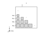
- FIG. 1 is a diagram for explaining an outline of the radio wave control board.
- FIG. 2 is a diagram for explaining the transmission direction of radio waves through the radio wave control plate.
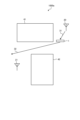
- FIG. 3 is a diagram showing a communication system according to a comparative example.
- FIG. 4 is a diagram illustrating an example of the configuration of a communication system according to a first example of the first embodiment.
- FIG. 5 is a diagram illustrating an example of the configuration of a communication system according to a second example of the first embodiment.
- FIG. 6 is a diagram illustrating an example of the configuration of a communication system according to a third example of the first embodiment.
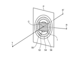
- FIG. 7 is a diagram for explaining a method for setting the size of the radio wave control plate according to the second embodiment.
- FIG. 1 is a diagram for explaining an outline of the radio wave control board.
- FIG. 2 is a diagram for explaining the transmission direction of radio waves through the radio wave control plate.
- FIG. 3 is a diagram showing a communication system according to a comparative
- FIG. 8 is a diagram showing the relationship between the size of the radio wave control board and the received power of the radio wave control board according to the second embodiment.
- FIG. 9 is a diagram for explaining the effective range of the refraction angle of the radio wave control band according to the third embodiment.
- FIG. 10 is a diagram for explaining the beam pattern of the radio wave control plate according to the third embodiment.
- an XYZ Cartesian coordinate system is set, and the positional relationship of each part is explained with reference to this XYZ Cartesian coordinate system.
- the direction parallel to the X-axis in a horizontal plane is defined as the X-axis direction
- the direction parallel to the Y-axis in the horizontal plane perpendicular to the X-axis is defined as the Y-axis direction
- the direction parallel to the Z-axis perpendicular to the horizontal plane is defined as the Z-axis direction.
- the plane containing the X-axis and Y-axis will be appropriately referred to as the XY plane
- the plane containing the X-axis and Z-axis will be appropriately referred to as the XZ plane
- the plane containing the Y-axis and Z-axis will be appropriately referred to as the YZ plane.
- the XY plane is parallel to the horizontal plane.
- the XY plane, XZ plane, and YZ plane are perpendicular to each other.
- Fig. 1 is a diagram for explaining the outline of the radio wave control plate.
- the radio wave control plate 1 is a plate-shaped member configured to be able to reflect or refract radio waves transmitted by a base station. For example, when the radio wave control plate 1 receives radio waves transmitted by a base station, it is configured to reflect or refract the radio waves at a predetermined angle.
- the radio wave control plate 1 can be configured, for example, from a metamaterial that changes the phase of the incident wave.
- the radio wave control plate 1 may include, for example, a substrate 2, a unit structure 10a, a unit structure 10b, a unit structure 10c, and a unit structure 10d.
- unit structures 10a to 10d When there is no need to distinguish between unit structures 10a to 10d, they are collectively referred to as unit structures 10.
- the unit structure 10a, the unit structure 10b, the unit structure 10c, and the unit structure 10d may be formed on a substrate 2.
- the substrate 2 may be, for example, a dielectric substrate formed of a dielectric material.
- the substrate 2 may have, for example, but is not limited to, a rectangular shape.
- the unit structure 10a, the unit structure 10b, the unit structure 10c, and the unit structure 10d may be arranged two-dimensionally.
- Unit structure 10a, unit structure 10b, unit structure 10c, and unit structure 10d each have a different size.
- unit structure 10a is the largest, followed by unit structure 10b, unit structure 10c, and unit structure 10d in order of size.
- radio wave control plate 1 has a structure in which multiple unit structures 10 of different sizes are periodically arranged.
- Each of unit structures 10a to 10d may have a different amount of phase change in the received radio waves. That is, unit structures 10a to 10d are periodically arranged so that there is a gradient in the amount of phase change. Each of unit structures 10a to 10d has a rectangular shape, but is not limited to this. By changing the size and shape of unit structures 10a to 10d, the frequency band and amount of phase change of the radio waves to be reflected or refracted can be adjusted.
- FIG. 2 is a diagram for explaining the refraction direction of radio waves of the radio wave control board.
- the radio wave control board 1 shown in FIG. 2 is a refraction-type radio wave control board that refracts received radio waves at a predetermined angle and emits them. For example, when the radio wave control board 1 receives radio waves 31 transmitted from the transmitting device 20, it emits refracted waves 32 that have been refracted in a predetermined direction. Range R indicates the range in which the radio wave control board 1 can refract radio waves. The radio wave control board 1 cannot refract the radio waves 31 by more than 90° with respect to the traveling direction of the radio waves.
- the transmitting device 20 is, for example, a base station, but is not limited to this.
- FIG. 3 is a diagram showing a communication system according to a comparative example.
- the communication system 1000a includes a radio wave control plate 1, a transmitting device 20, and a receiving device 21.
- the receiving device 21 is a relay device that relays radio waves or a terminal device such as a smartphone used by a user, but is not limited to these.
- a communication system is configured that allows appropriate communication between the transmitting device 20 and the receiving device 21 even in an environment where radio wave visibility between the transmitting device 20 and the receiving device 21 is not ensured.
- FIG. 4 is a diagram showing an example of the configuration of a communication system according to the first example of the first embodiment.
- the communication system 1000 includes a first radio wave control board 1-1, a second radio wave control board 1-2, a transmitting device 20, and a receiving device 21. Obstacles 43 and 44 that block radio waves are located around the transmitting device 20 and the receiving device 21. In the example shown in FIG. 4, the receiving device 21 is located between the obstacles 43 and 44. Therefore, there is no line of sight between the transmitting device 20 and the receiving device 21 for radio waves.
- the first radio wave control board 1-1 is placed at a first installation position where it can receive radio waves 31 transmitted by the transmitting device 20.
- the first radio wave control board 1-1 is a refracting type radio wave control board that refracts the received radio waves at a predetermined angle and emits the waves.
- the first radio wave control board 1-1 refracts the radio waves 31 at a predetermined angle and emits refracted waves 32.
- the second radio wave control board 1-2 is placed at a second installation position where it can receive the refracted wave 32 emitted by the first radio wave control board 1-1.
- the second radio wave control board 1-2 is a refracting type radio wave control board that refracts the received radio waves at a predetermined angle and emits them.
- the second radio wave control board 1-2 refracts the refracted wave 32 in the direction of the receiving device 21 and emits the refracted wave 33.
- the receiving device 21 receives the refracted wave 33 emitted by the second radio wave control board 1-2. That is, the transmitting device 20 and the receiving device 21 can communicate via the first radio wave control board 1-1 and the second radio wave control board 1-2.
- the first radio wave control board 1-1 and the second radio wave control board 1-2 can ensure line of sight of the radio waves between the transmitting device 20 and the receiving device 21 by bending the radio waves 31 transmitted by the transmitting device 20 by 90 degrees relative to the direction of travel of the radio waves 31. This allows the transmitting device 20 and the receiving device 21 to communicate appropriately.
- FIG. 5 is a diagram showing an example of the configuration of a communication system according to the second example of the first embodiment.
- the communication system 1000A includes a first radio wave control board 1-1, a second radio wave control board 1-2, a transmitting device 20, and a receiving device 21. Obstacles 45 and 46 that block radio waves are located around the transmitting device 20 and the receiving device 21. In the example shown in FIG. 5, the receiving device 21 is located behind the obstacles 45 and 46 as seen from the transmitting device 20. Therefore, there is no line of sight between the transmitting device 20 and the receiving device 21 for radio waves.
- the first radio wave control board 1-1 is also placed at a first installation position where it can receive radio waves 31 transmitted by the transmitting device 20.
- the first radio wave control board 1-1 refracts the radio waves 31 at a predetermined angle and emits a refracted wave 32.
- the second radio wave control board 1-2 is placed at a second installation position where it can receive the refracted wave 32 emitted by the first radio wave control board 1-1.
- the first radio wave control board 1-1 refracts the refracted wave 32 in the direction of the receiving device 21 and emits a refracted wave 33.
- the receiving device 21 receives the refracted wave 33 emitted by the second radio wave control board 1-2.
- FIG. 6 is a diagram showing an example of the configuration of a communication system according to the third example of the first embodiment.
- the communication system 1000B includes a first radio wave control board 1-1, a second radio wave control board 1-2, a transmitting device 20, and a receiving device 21. Obstacles 47 and 48 that block radio waves are located around the transmitting device 20 and the receiving device 21. In the example shown in FIG. 6, the receiving device 21 is located in a place surrounded by obstacles 47 and 48. Therefore, there is no line of sight between the transmitting device 20 and the receiving device 21 for radio waves.
- the first radio wave control board 1-1 is also placed in a first installation position where it can receive radio waves 31 transmitted by the transmitting device 20.
- the first radio wave control board 1-1 refracts the radio waves 31 at a predetermined angle and emits a refracted wave 32.
- the second radio wave control board 1-2 is placed at a second installation position where it can receive the refracted wave 32 emitted by the first radio wave control board 1-1.
- the second radio wave control board 1-2 is a reflective radio wave control board that reflects the received radio wave at a predetermined angle and emits it.
- the communication system 1000B includes a refracted radio wave control board and a reflective radio wave control board.
- the second radio wave control board 1-2 reflects the refracted wave 32 in the direction of the receiving device 21 and emits a reflected wave 34.
- the receiving device 21 receives the reflected wave 34 emitted by the second radio wave control board 1-2. That is, the transmitting device 20 and the receiving device 21 can communicate via the first radio wave control board 1-1 and the second radio wave control board 1-2.
- the first radio wave control board 1-1 and the second radio wave control board 1-2 can ensure line of sight of the radio waves between the transmitting device 20 and the receiving device 21 by refracting and reflecting the radio waves 31 transmitted by the transmitting device 20. This allows the transmitting device 20 and the receiving device 21 to communicate appropriately.
- the radio wave control plate 1 includes a plurality of unit structures 10.
- the phase distribution of the radio wave control plate 1 provides a phase difference between adjacent unit structures 10 so as to change the direction of travel of the radio wave. If the phase difference between adjacent unit structures is ⁇ , the reflection angle or refraction angle when the incident angle is 0° (when the radio wave is incident from the front of the radio wave control plate 1) is ⁇ , the interval between adjacent unit structures 10 is d, and the wave number is k, then it is preferable to set ⁇ so as to satisfy the following formula (1).
- the condition of formula (1) indicates the condition under which radio waves incident on the radio wave control board 1 as plane waves reinforce each other at infinity after reflection or refraction.
- the condition of the phase distribution of the radio wave control board 1 is not limited to the condition shown in formula (1).
- the phase distribution of the first radio wave control board 1-1 may be set so that the refracted wave 32 emitted by the first radio wave control board 1-1 converges at the position of the second radio wave control board 1-2.
- the phase distribution of the second radio wave control board 1-2 may be set so that the refracted wave 33 emitted by the second radio wave control board 1-2 converges at the position of the receiving device 21.
- the radio wave control board 1 may also have a phase distribution that does not have a convergence point and the beam width of the incident plane wave widens after reflection or refraction.
- two radio wave control plates 1 are used to ensure line of sight between the transmitting device 20 and the receiving device 21, but the present disclosure is not limited to this.
- three or more radio wave control plates 1 may be used to ensure line of sight between the transmitting device 20 and the receiving device 21.
- the radio waves transmitted by the transmitting device 20 can be bent in various directions, so that line of sight between the transmitting device 20 and the receiving device 21 can be more appropriately ensured regardless of the positional relationship between the transmitting device 20 and the receiving device 21.
- the radio wave control plate 1 is capable of reflecting or refracting both horizontally polarized waves and vertically polarized waves (hereinafter also referred to as both polarized waves). This is because, when the transmitting device 20 transmits radio waves of both polarized waves, a radio wave control plate capable of reflecting or refracting both polarized waves can deliver more power to the receiving device 21 than a radio wave control plate capable of reflecting or refracting only one of the horizontally polarized waves and the vertically polarized waves. This is also true in the following embodiments.
- Radio wave control plate 1 e.g., the length of one side
- the receiving device 21 may not be able to receive effective power. Therefore, in the second embodiment, the size of the radio wave control plate is appropriately configured.
- Fig. 7 is a diagram for explaining a method for setting the size of the radio wave control plate according to the second embodiment.
- the size of the radio wave control plate 1 is set based on the Fresnel zone. Specifically, the size of the radio wave control plate 1 is set to be equal to or smaller than the first Fresnel radius.
- center point C indicates the center point of the radio wave control board 1.
- Transmission point T indicates the transmission point of the radio wave.
- Reception point R indicates the reception point of the outgoing wave emitted from the radio wave control board 1.
- Reception point R' indicates a virtual reception point.
- the straight-line distance between center point C and reception point R is the same as the straight-line distance between center point C and reception point R'.
- the circle of radius r1 defined by equation (2) is called the first Fresnel zone 50.
- Radius r1 is called the first Fresnel radius.
- the first Fresnel zone 50, the second Fresnel zone 52, the third Fresnel zone 54, and the fourth Fresnel zone 56 are shown.
- the first Fresnel zone 50 and the third Fresnel zone 54 are odd-order Fresnel zones.
- the second Fresnel zone 52 and the fourth Fresnel zone 56 are even-order Fresnel zones.
- it is preferable that the size of the radio wave control plate 1 is equal to or greater than the first Fresnel radius.
- FIG. 8 is a diagram showing the relationship between the size of the radio wave control plate of the second embodiment and the received power.
- the waveform 101 shown in FIG. 8 represents the result of calculating the received power of the radio wave control plate 1 having a side length of X [m] that satisfies the formula (1) by changing X.
- the frequency of the radio wave is 28 [GHz (gigahertz)]
- the antenna gain of the receiving point R (receiving device) is 0 [dBi (decibels)]
- d TM 50 [m]
- d MR 5 [m].
- the line 102 represents the first Fresnel radius.
- the line 103 represents the received power received at 55 [m], which is the straight line distance from the transmission point T to the receiving point R' that passes through the center point C of the radio wave control plate 1.
- the received power of radio wave control board 1 is equal to the received power received at a straight line distance of 55 [m] from transmission point T to reception point R' passing through center point C of radio wave control board 1.
- the size of radio wave control board 1 is equal to or larger than the first Fresnel radius.
- the transmitting device 20 when viewed from the first radio wave control board 1-1, corresponds to the transmitting point T, and the second radio wave control board 1-2 corresponds to the receiving point R'.
- the first radio wave control board 1-1 corresponds to the transmitting point T
- the receiving device 21 corresponds to the receiving point R'.
- the size of the first radio wave control board 1-1 is L1, the size of the second radio wave control board 1-2 is L2, the distance between the transmitting device 20 and the first radio wave control board 1-1 is d T1 , the distance between the first radio wave control board 1-1 and the second radio wave control board 1-2 is d 12 , and the distance between the second radio wave control board 1-2 and the receiving device 21 is d 2R .
- the size L1 of the first radio wave control board 1-1 and the size L2 of the second radio wave control board 1-2 satisfy the relationship of the following formula (3) and formula (4).
- the size L1 and the size L2 are the shorter sides of the first radio wave control plate 1-1 and the second radio wave control plate 1-2, respectively.
- the second radio wave control board 1-2 can receive effective power from the first radio wave control board 1-1, and the receiving device 21 can receive effective power from the second radio wave control board 1-2.
- Fig. 9 is a diagram for explaining the effective range of the refraction angle of the radio wave control band according to the third embodiment.
- the first radio wave control board 1-1 is disposed opposite the transmitting device 20.
- the vector from the first radio wave control board 1-1 toward the center of the first radio wave control board 1-1 is defined as vector a.
- Vector a indicates the traveling direction of the radio waves transmitted by the transmitting device 20 to the first radio wave control board 1-1.
- the first radio wave control board 1-1 refracts the radio waves from the transmitting device 20, refracting them in the ⁇ 1 direction and emitting them to the center of the second radio wave control board 1-2.
- the vector from the center of the first radio wave control board 1-1 toward the center of the second radio wave control board 1-2 is defined as vector b. In this case, the relationship in equation (5) holds.
- FIG. 10 is a diagram for explaining the beam pattern of the radio wave control plate according to the third embodiment.
- the horizontal axis indicates angle [deg (degrees)] and the vertical axis indicates received power [dB (decibels)].
- Beam pattern 110 shows the beam pattern of radio waves that have passed through the radio wave control plate 1.
- the angle range in which the power received in the ⁇ direction is reduced by 3 [dB] is defined as the beam half-value angle ⁇ . If ⁇ deviates from equation (5) within ⁇ , effective power within "maximum received power - 3 [dB]" can be obtained.
- the vector from the transmitting device 20 to the center of gravity of the first radio wave control board 1-1 is vector a.
- the vector from the center of the first radio wave control board 1-1 to the center of the second radio wave control board 1-2 is vector b.
- the vector from the center of the second radio wave control board 1-2 toward the receiving device 21 is vector c.
- the beam half-value angle of the refracted wave 32 is ⁇ 1.
- the beam half-value angle of the refracted wave 33 is ⁇ 2. If the refraction angle or reflection angle of the first radio wave control board 1-1 is ⁇ 1, the first radio wave control board 1-1 is configured to satisfy the following formula (6). If the refraction angle or reflection angle of the second radio wave control board 1-2 is ⁇ 2, the second radio wave control board 1-2 is configured to satisfy the following formula (7).
- the first radio wave control plate 1-1 and the second radio wave control plate 1-2 are configured to satisfy formulas (6) and (7), respectively, so that the receiving device 21 can properly receive effective power.
- a communication system 1000 includes a first radio wave control board 1-1 and a second radio wave control board 1-2, and the first radio wave control board 1-1 refracts or reflects radio waves transmitted from a transmitting device 20 in the direction of the second radio wave control board 1-2, and the second radio wave control board 1-2 refracts or reflects radio waves emitted from the first radio wave control board 1-1 in the direction of a receiving device 21 or in the direction of a third radio wave control board.
- the present disclosure can ensure line of sight of radio waves between the transmitting device 20 and the receiving device 21 by using multiple radio wave control boards.
- the communication system 1000 according to the second aspect of the present disclosure is the communication system 1000 according to the first aspect, in which the first radio wave control board 1-1 and the second radio wave control board 1-2 are capable of refracting or reflecting horizontally polarized waves and vertically polarized waves.
- the present disclosure allows the first radio wave control board 1-1 and the second radio wave control board 1-2 to appropriately refract or reflect radio waves, thereby appropriately ensuring line of sight of radio waves between the transmitting device 20 and the receiving device 21.
- the communication system 1000 according to the third aspect of the present disclosure is the communication system 1000 according to the first or second aspect, in which the first radio wave control board 1-1 and the second radio wave control board 1-2 include a plurality of unit structures 10 arranged two-dimensionally, and the phase difference ⁇ between adjacent unit structures 10 satisfies the following formula (1), where ⁇ is the reflection angle or refraction angle when the angle of incidence of the radio waves on the first radio wave control board 1-1 and the second radio wave control board 1-2 is 0°, d is the distance between adjacent unit structures, and k is the wave number of the radio waves transmitted from the transmitting device 20.
- ⁇ is the reflection angle or refraction angle when the angle of incidence of the radio waves on the first radio wave control board 1-1 and the second radio wave control board 1-2 is 0°
- d is the distance between adjacent unit structures
- k is the wave number of the radio waves transmitted from the transmitting device 20.
- the first radio wave control board 1-1 and the second radio wave control board 1-2 can appropriately refract or reflect the radio waves, and therefore the line of sight of the radio waves between the transmitting device 20 and the receiving device 21 can be appropriately ensured.
- the communication system 1000 according to the fourth aspect of the present disclosure is the communication system 1000 according to the first or second aspect, in which the phase distribution of the first radio wave control board 1-1 is set so that the reflected or refracted radio waves are focused at the position of the second radio wave control board 1-2.
- the present disclosure allows the first radio wave control board 1-1 to appropriately refract or reflect radio waves, thereby appropriately ensuring line of sight of radio waves between the transmitting device 20 and the receiving device 21.
- a communication system 1000 according to a fifth aspect of the present disclosure is a communication system 1000 according to any one of the first to fourth aspects, in which the length L1 of the short side of the first radio wave control board 1-1 satisfies the following formula (3) when the wavelength of the radio wave transmitted from the transmitting device 20 is ⁇ , the distance between the transmitting device 20 and the first radio wave control board 1-1 is d T1 , and the distance between the first radio wave control board 1-1 and the second radio wave control board 1-2 is d 12 , and the length L2 of the short side of the second radio wave control board 1-2 satisfies the following formula (4) when the distance between the second radio wave control board 1-2 and the receiving device 21 is d 2R .
- the present disclosure can appropriately set the sizes of the first radio wave control board 1-1 and the second radio wave control board 1-2 to deliver effective power to the receiving device 21, and therefore can appropriately ensure the visibility of the radio waves between the transmitting device 20 and the receiving device 21.
- a communication system 1000 relating to a sixth aspect of the present disclosure is a communication system 1000 relating to any of the first to fifth aspects, in which the refraction angle or reflection angle ⁇ 1 of the first radio wave control board 1-1 satisfies the following formula (6) when the vector from the transmitting device 20 toward the center of the first radio wave control board 1-1 is vector a, the vector from the center of the first radio wave control board 1-1 toward the center of the second radio wave control board 1-2 is vector b, and the beam half-value angle of the radio waves emitted from the first radio wave control board 1-1 is vector ⁇ 1, and the refraction angle or reflection angle ⁇ 2 of the second radio wave control board 1-2 satisfies the following formula (7) when the vector from the center of the second radio wave control board 1-2 toward the receiving device 21 is vector c, and the beam half-value angle of the radio waves emitted from the second radio wave control board 1-2 is vector ⁇ 2.
- the present disclosure can appropriately set the refraction or reflection angle of the first radio wave control plate 1-1 and the second radio wave control plate 1-2 to deliver effective power to the receiving device 21, thereby ensuring appropriate visibility of radio waves between the transmitting device 20 and the receiving device 21.
- the communication system 1000 according to the seventh aspect of the present disclosure is a communication system 1000 according to any one of the first to sixth aspects, and uses a first radio wave control board 1-1 and a second radio wave control board 1-2 to bend the radio waves transmitted by the transmitting device 20 by 90 degrees or more relative to the direction in which the transmitting device 20 transmitted the radio waves. This allows the present disclosure to properly ensure line of sight of the radio waves between the transmitting device 20 and the receiving device 21.
- the communication system 1000 according to the eighth aspect of the present disclosure is a communication system 1000 according to any one of the first to seventh aspects, and in an environment where line of sight of radio waves between the transmitting device 20 and the receiving device 21 is not ensured, the radio waves transmitted by the transmitting device 20 are refracted or reflected using the first radio wave control board 1-1 and the second radio wave control board 1-2 to ensure line of sight of radio waves between the transmitting device 20 and the receiving device 21.
- the present disclosure can appropriately ensure line of sight of radio waves between the transmitting device 20 and the receiving device 21 in an environment where line of sight of radio waves between the transmitting device 20 and the receiving device 21 is not ensured.
- the method of installing a radio wave control board includes the steps of installing a first radio wave control board 1-1 at a first installation position so that the radio waves transmitted by the transmitting device 20 are refracted or reflected in the direction of the second radio wave control board 1-2, and installing a second radio wave control board 1-2 at a second installation position so that the radio waves emitted from the first radio wave control board 1-1 are refracted or reflected in the direction of the receiving device 21 or in the direction of the third radio wave control board.
- the present disclosure can ensure line of sight of radio waves between the transmitting device 20 and the receiving device 21 by installing multiple radio wave control boards 1 between the transmitting device 20 and the receiving device 21.
- Radio wave control plate 1-1 First radio wave control plate 1-2 Second radio wave control plate 10
- Unit structure 20 Transmitting device 21
- Receiving device 31 Radio wave 32, 33 Refracted wave 34 Reflected wave 41, 42, 43, 44, 45, 46, 47, 48 Obstacle 50
- First Fresnel zone 52 Second Fresnel zone 54
- Third Fresnel zone 56 Fourth Fresnel zone
Landscapes
- Physics & Mathematics (AREA)
- Electromagnetism (AREA)
- Aerials With Secondary Devices (AREA)
Priority Applications (1)
| Application Number | Priority Date | Filing Date | Title |
|---|---|---|---|
| JP2025529691A JPWO2025004939A1 (https=) | 2023-06-28 | 2024-06-19 |
Applications Claiming Priority (2)
| Application Number | Priority Date | Filing Date | Title |
|---|---|---|---|
| JP2023-106316 | 2023-06-28 | ||
| JP2023106316 | 2023-06-28 |
Publications (1)
| Publication Number | Publication Date |
|---|---|
| WO2025004939A1 true WO2025004939A1 (ja) | 2025-01-02 |
Family
ID=93938356
Family Applications (1)
| Application Number | Title | Priority Date | Filing Date |
|---|---|---|---|
| PCT/JP2024/022280 Ceased WO2025004939A1 (ja) | 2023-06-28 | 2024-06-19 | 通信システム、および電波制御板の設置方法 |
Country Status (2)
| Country | Link |
|---|---|
| JP (1) | JPWO2025004939A1 (https=) |
| WO (1) | WO2025004939A1 (https=) |
Cited By (1)
| Publication number | Priority date | Publication date | Assignee | Title |
|---|---|---|---|---|
| WO2026083760A1 (ja) * | 2024-10-18 | 2026-04-23 | 株式会社ジャパンディスプレイ | 電波反射装置の駆動方法 |
Citations (3)
| Publication number | Priority date | Publication date | Assignee | Title |
|---|---|---|---|---|
| WO2022091986A1 (ja) * | 2020-10-30 | 2022-05-05 | 京セラ株式会社 | 通信システム、通信方法、および電波屈折板の設置方法 |
| WO2022091660A1 (ja) * | 2020-10-28 | 2022-05-05 | 住友電気工業株式会社 | 反射ユニット及び無線伝送システム |
| JP2022165403A (ja) * | 2021-04-19 | 2022-10-31 | 京セラ株式会社 | 電波屈折板 |
-
2024
- 2024-06-19 JP JP2025529691A patent/JPWO2025004939A1/ja active Pending
- 2024-06-19 WO PCT/JP2024/022280 patent/WO2025004939A1/ja not_active Ceased
Patent Citations (3)
| Publication number | Priority date | Publication date | Assignee | Title |
|---|---|---|---|---|
| WO2022091660A1 (ja) * | 2020-10-28 | 2022-05-05 | 住友電気工業株式会社 | 反射ユニット及び無線伝送システム |
| WO2022091986A1 (ja) * | 2020-10-30 | 2022-05-05 | 京セラ株式会社 | 通信システム、通信方法、および電波屈折板の設置方法 |
| JP2022165403A (ja) * | 2021-04-19 | 2022-10-31 | 京セラ株式会社 | 電波屈折板 |
Cited By (1)
| Publication number | Priority date | Publication date | Assignee | Title |
|---|---|---|---|---|
| WO2026083760A1 (ja) * | 2024-10-18 | 2026-04-23 | 株式会社ジャパンディスプレイ | 電波反射装置の駆動方法 |
Also Published As
| Publication number | Publication date |
|---|---|
| JPWO2025004939A1 (https=) | 2025-01-02 |
Similar Documents
| Publication | Publication Date | Title |
|---|---|---|
| US20250174903A1 (en) | Frequency-selective reflecting plate and communication relay system | |
| US8390531B2 (en) | Reflect array | |
| JP2019519988A (ja) | アンテナアレイ内の相互結合を低減するための装置および方法 | |
| JPWO2022091660A5 (https=) | ||
| WO2025004939A1 (ja) | 通信システム、および電波制御板の設置方法 | |
| JP2021057722A (ja) | 電波透過板および電波透過システム | |
| JP2006279525A (ja) | アンテナ | |
| JP7255678B2 (ja) | アンテナ装置及びその設計方法 | |
| EP4661214A1 (en) | Radio wave refraction plate | |
| WO2024162166A1 (ja) | 電波反射板 | |
| US20260051662A1 (en) | Radio wave lens | |
| WO2023210414A1 (ja) | 通信システム、電波屈折板および電波屈折板の設置位置の算出方法 | |
| JP2020188434A (ja) | アンテナ装置 | |
| WO2023234082A1 (ja) | 電波制御板および通信システム | |
| US20260100506A1 (en) | Passive reflectors providing phase distribution and methods of fabricating the same | |
| WO2024142824A1 (ja) | 電波制御板の設置方法および通信システム | |
| JP7057457B2 (ja) | ホーンアンテナ及びホーンアンテナアレイ | |
| JP2026050199A (ja) | アンテナ装置 | |
| JP6873802B2 (ja) | ホーンアンテナ及びホーンアンテナアレイ | |
| CN117882249A (zh) | 频率选择反射板和通信中继系统 | |
| JP6836475B2 (ja) | 無線通信システム、無線通信方法及び無線通信装置 | |
| WO2022239660A1 (ja) | リフレクタシステム、アクティブリフレクタ、及び、アクティブリフレクタの配置方法 | |
| WO2024014411A1 (ja) | 無線通信システムおよび無線通信方法 | |
| JPH03125505A (ja) | 開口面アンテナ装置 | |
| JPH02274003A (ja) | 双焦点アンテナ |
Legal Events
| Date | Code | Title | Description |
|---|---|---|---|
| 121 | Ep: the epo has been informed by wipo that ep was designated in this application |
Ref document number: 24831801 Country of ref document: EP Kind code of ref document: A1 |
|
| ENP | Entry into the national phase |
Ref document number: 2025529691 Country of ref document: JP Kind code of ref document: A |
|
| WWE | Wipo information: entry into national phase |
Ref document number: 2025529691 Country of ref document: JP |
|
| NENP | Non-entry into the national phase |
Ref country code: DE |