WO2025004874A1 - 回転リフレクタ - Google Patents
回転リフレクタ Download PDFInfo
- Publication number
- WO2025004874A1 WO2025004874A1 PCT/JP2024/021833 JP2024021833W WO2025004874A1 WO 2025004874 A1 WO2025004874 A1 WO 2025004874A1 JP 2024021833 W JP2024021833 W JP 2024021833W WO 2025004874 A1 WO2025004874 A1 WO 2025004874A1
- Authority
- WO
- WIPO (PCT)
- Prior art keywords
- sleeve
- rotating
- rotating reflector
- rotation
- reflector according
- Prior art date
- Legal status (The legal status is an assumption and is not a legal conclusion. Google has not performed a legal analysis and makes no representation as to the accuracy of the status listed.)
- Ceased
Links
Images









Classifications
-
- F—MECHANICAL ENGINEERING; LIGHTING; HEATING; WEAPONS; BLASTING
- F21—LIGHTING
- F21S—NON-PORTABLE LIGHTING DEVICES; SYSTEMS THEREOF; VEHICLE LIGHTING DEVICES SPECIALLY ADAPTED FOR VEHICLE EXTERIORS
- F21S41/00—Illuminating devices specially adapted for vehicle exteriors, e.g. headlamps
- F21S41/60—Illuminating devices specially adapted for vehicle exteriors, e.g. headlamps characterised by a variable light distribution
- F21S41/67—Illuminating devices specially adapted for vehicle exteriors, e.g. headlamps characterised by a variable light distribution by acting on reflectors
- F21S41/675—Illuminating devices specially adapted for vehicle exteriors, e.g. headlamps characterised by a variable light distribution by acting on reflectors by moving reflectors
-
- F—MECHANICAL ENGINEERING; LIGHTING; HEATING; WEAPONS; BLASTING
- F21—LIGHTING
- F21V—FUNCTIONAL FEATURES OR DETAILS OF LIGHTING DEVICES OR SYSTEMS THEREOF; STRUCTURAL COMBINATIONS OF LIGHTING DEVICES WITH OTHER ARTICLES, NOT OTHERWISE PROVIDED FOR
- F21V7/00—Reflectors for light sources
-
- F—MECHANICAL ENGINEERING; LIGHTING; HEATING; WEAPONS; BLASTING
- F21—LIGHTING
- F21W—INDEXING SCHEME ASSOCIATED WITH SUBCLASSES F21K, F21L, F21S and F21V, RELATING TO USES OR APPLICATIONS OF LIGHTING DEVICES OR SYSTEMS
- F21W2102/00—Exterior vehicle lighting devices for illuminating purposes
- F21W2102/10—Arrangement or contour of the emitted light
- F21W2102/13—Arrangement or contour of the emitted light for high-beam region or low-beam region
Definitions
- the present invention relates to a rotating reflector.
- an optical unit that includes a rotating reflector that rotates in one direction around a rotation axis while reflecting light emitted from a light source (see Patent Document 1).
- the rotating reflector included in this optical unit has a reflective surface so that the light from the light source that is reflected while rotating forms a desired light distribution pattern.
- a sleeve is fixed to the rotating part, which is the center of rotation, by insert molding.
- the sleeve is a cylindrical member with a hole into which the rotating shaft of the motor is inserted and fitted.
- the sleeve also needs to be fixed to the rotating part so that it does not come off the rotating reflector body or spin freely. Therefore, methods have been devised to firmly fix the sleeve to the rotating part by forming a knurl on the outer periphery of the sleeve or by forming multiple grooves (splines) in the axial direction of the outer periphery.
- the present invention was made in consideration of these circumstances, and one of its objectives is to provide a new rotating reflector that can stably form a desired light distribution pattern.
- one embodiment of the rotating reflector of the present invention is a rotating reflector that includes a rotating part and a resin body part that is provided around the rotating part and has blades that function as a reflective surface, the rotating part has a sleeve fixed thereto into which the rotating shaft of a motor is press-fitted, the sleeve has a rotation prevention part formed on its outer circumferential surface that includes a plurality of first surfaces and second surfaces that connect the first surfaces and have a larger radius of curvature than the first surfaces, and the rotation prevention part is configured so that the boundary between the first surface and the second surface is convex outward.
- the boundary of the anti-rotation portion is convex toward the outside.
- the inner peripheral surface of the rotating portion to which the sleeve is fixed is formed with a concave portion that corresponds to the convex portion mentioned above. Since stress is less likely to concentrate in the concave portion and is dispersed to the gently curved or flat surface adjacent to the concave portion, the portion of the rotating portion to which the sleeve is fixed is less likely to deform even if it is made of resin.
- the anti-rotation portion may have a shape that is n-fold symmetric (2 ⁇ n ⁇ 6) when viewed from the direction along the rotation axis. This allows the parts to which stress is applied to be arranged symmetrically, making it less likely that localized stress concentrations will occur.
- the first surface may be an arc and the second surface may be a plane. This allows stress to be distributed on the inner circumferential surface of the rotating part that contacts the second surface of the sleeve when the rotating reflector rotates.
- the outer peripheral surface may be formed with a stopper portion having a recess that is recessed toward the center more than the anti-rotation portion when viewed from the direction along the rotation axis. This makes it possible to suppress movement in the direction of the rotation axis even if a force is applied to the sleeve in the direction of the rotation axis.
- the sleeve may be symmetrical from top to bottom when the direction along the rotation axis is taken as the up-down direction. This prevents the sleeve from being attached to the rotating part with the wrong top and bottom, improving workability during manufacturing.
- the recess may be covered with the resin of the main body. This allows the resin covering the recess to function as a retaining part to prevent it from coming loose.
- the sleeve may be fixed to the rotating part by resin that is insert molded together with the main body part. This allows a rotating reflector with a fixed sleeve to be manufactured in a simple process.
- the sleeve may be a metal component that has been machined.
- the cutting oil used during machining may affect the properties of the resin. For example, even if the resin is easily deformed by cutting oil, the shape of the sleeve that is fixed to the rotating part is designed to prevent a decrease in rotation accuracy due to deformation of the rotating part.
- the present invention provides a new rotating reflector that can form a desired light distribution pattern.
- FIG. 1 is a schematic horizontal cross-sectional view of a vehicle headlamp according to an embodiment of the present invention
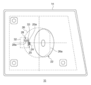
- 1 is a front view of a vehicle headlamp according to an embodiment of the present invention
- FIG. 2 is a perspective view showing a main part of an optical unit according to the present embodiment.
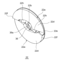
- FIG. 2 is a perspective view of a rotating reflector according to the present embodiment.
- FIG. 2 is a front view of the rotating reflector according to the present embodiment.
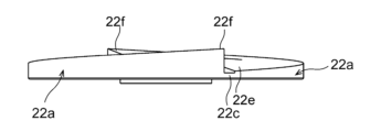
- 6 is a side view of the rotating reflector shown in FIG. 5 as viewed from a direction A. 6 is a cross-sectional view of the rotating reflector shown in FIG. 5 taken along the line BB.
- FIG. 8A is a perspective view of a sleeve according to a reference example
- FIG. 8B is a top view of the sleeve according to the reference example
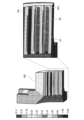
- 13A and 13B are schematic diagrams showing simulation results of stress generated in a tubular portion of a main body according to a reference example.
- FIG. 10A is a perspective view of the sleeve according to the first embodiment
- FIG. 10B is a top view of the sleeve according to the first embodiment.
- 5A to 5C are schematic diagrams illustrating simulation results of stress generated in a tubular portion of the main body according to the first embodiment.
- 12(a) to 12(c) are schematic diagrams for explaining the mechanism by which the sleeve is displaced within the through hole due to thermal cycles.
- FIG. 11 is a perspective view of a sleeve according to a second embodiment.
- 14(a) is a side view of the sleeve shown in FIG. 13
- FIG. 14(b) is a top view of the sleeve shown in FIG. 13
- FIG. 14(c) is a CC cross-sectional view of the sleeve shown in FIG. 14(b).
- FIG. 11 is a perspective view of a sleeve according to a third embodiment.
- the rotating reflector according to this embodiment rotates while reflecting light emitted from a light source, and can be used in a variety of vehicle lamps.
- a vehicle headlamp that can be equipped with a rotating reflector according to the embodiment described below will be described.
- Fig. 1 is a schematic horizontal cross-sectional view of a vehicle headlamp according to the present embodiment.
- Fig. 2 is a front view of the vehicle headlamp according to the present embodiment. Note that some components are omitted in Fig. 2.
- the vehicle headlamp 10 in this embodiment is a right-side headlamp mounted on the right side of the front end of the vehicle, and has the same structure as the headlamp mounted on the left side, except that it is symmetrical. Therefore, the following will provide a detailed description of the right-side vehicle headlamp 10, and will omit a description of the left-side vehicle headlamp.
- a vehicle headlamp 10 is equipped with a lamp body 12 having a recess that opens toward the front.
- the front opening of the lamp body 12 is covered by a transparent front cover 14 to form a lamp chamber 16.
- the lamp chamber 16 functions as a space that houses one optical unit 18.
- the optical unit 18 is a lamp unit that is configured to be able to emit a variable high beam.
- a variable high beam is one that is controlled to change the shape of the light distribution pattern for high beams, and can, for example, create a non-illuminated area (light-shielding area) in part of the light distribution pattern.
- the optical unit 18 includes a first light source 20, a focusing lens 24 as a primary optical system (optical member) that changes the optical path of the first light L1 emitted from the first light source 20 and directs it toward the blade 22a of the rotating reflector 22, a rotating reflector 22 that rotates around the rotation axis R while reflecting the first light L1, a convex lens 26 as a projection lens that projects the first light L1 reflected by the rotating reflector 22 in the light irradiation direction of the optical unit (rightward in FIG.
- a second light source 28 disposed between the first light source 20 and the convex lens 26, a diffusing lens 30 as a primary optical system (optical member) that changes the optical path of the second light L2 emitted from the second light source 28 and directs it toward the convex lens 26, and a heat sink 32 on which the first light source 20 and the second light source 28 are mounted.
- Each light source uses a semiconductor light-emitting element such as an LED, EL, or LD.
- a semiconductor light-emitting element such as an LED, EL, or LD.
- a plurality of LEDs 20a are arranged in an array on a circuit board 33.
- Each LED 20a is configured so that it can be turned on and off individually.
- the second light source 28 in this embodiment has two LEDs 28a arranged side by side in the horizontal direction in an array, and each LED 28a is configured to be able to be turned on and off individually.
- the second light source 28 is also arranged so that the second light L2 is incident on the convex lens 26 without being reflected by the rotating reflector 22. This allows the optical characteristics of the second light L2 emitted from the second light source 28 to be selected without taking into consideration that it will be reflected by the rotating reflector 22.
- the second light source 28 can be used as a light source that irradiates an area outside the vehicle.
- the rotating reflector 22 rotates in one direction around the rotation axis R by a driving source such as a motor 34.
- the rotating reflector 22 also has two blades 22a of the same shape arranged around a cylindrical rotating part 22b.
- the blades 22a function as a reflective surface configured to scan the front with the light emitted from the first light source 20 while rotating and reflecting the light, thereby forming a desired light distribution pattern.
- the rotation axis R of the rotating reflector 22 is oblique to the optical axis Ax, and is provided in a plane including the optical axis Ax and the first light source 20.
- the rotation axis R is provided approximately parallel to the scanning plane of the light (illumination beam) of the LED 20a that scans left and right by rotating. This allows the optical unit to be made thinner.
- the scanning plane can be considered to be, for example, a sector-shaped plane formed by continuously connecting the trajectories of the light of the LED 20a, which is the scanning light.
- the shape of the convex lens 26 may be selected as appropriate according to the light distribution characteristics, such as the required light distribution pattern and illuminance distribution, but it is also possible to use aspheric lenses or free-form lenses.
- the convex lens 26 of this embodiment can form a notch 26a in which part of the outer periphery is cut out vertically by devising the arrangement of each light source and rotating reflector 22. This makes it possible to reduce the size of the optical unit 18 in the vehicle width direction.
- the presence of the cutout portion 26a makes it less likely that the blade 22a of the rotating reflector 22 will interfere with the convex lens 26, allowing the convex lens 26 and the rotating reflector 22 to be closer together.
- a non-circular (straight line) portion is formed on the outer periphery of the convex lens 26, realizing a vehicle headlamp with an innovative design having a lens with an external shape that combines curves and straight lines when viewed from the front of the vehicle.
- FIG. 3 is a perspective view showing the main parts of the optical unit according to the present embodiment.
- Fig. 3 mainly shows the first light source 20, the rotating reflector 22, and the convex lens 26, and for the sake of convenience, some parts are omitted.
- the optical unit 18 includes a first light source 20 consisting of multiple LEDs 20a arranged in a horizontal line, and a convex lens 26 that projects light emitted from the first light source 20 and reflected by a rotating reflector 22 in the light irradiation direction (optical axis Ax) of the optical unit.
- the rotating reflector 22 is arranged so that its rotation axis R extends diagonally to the light irradiation direction (optical axis Ax) and in the horizontal direction.
- the first light source 20 is also arranged so that the light emitting surface of each of the multiple LEDs 20a is diagonal to the reflecting surface.
- the reflective surface 22d of the blade 22a has a twisted shape such that the angle between the optical axis Ax and the reflective surface changes as it moves in the circumferential direction around the rotation axis R.
- the shape of the reflective surface will be described in more detail later.
- Fig. 4 is a perspective view of the rotating reflector according to this embodiment.
- Fig. 5 is a front view of the rotating reflector according to this embodiment.
- Fig. 6 is a side view of the rotating reflector shown in Fig. 5, seen from direction A.
- Fig. 7 is a cross-sectional view taken along line B-B of the rotating reflector shown in Fig. 5.
- the rotating reflector 22 is a resin part having a rotating portion 22b and multiple (two) blades 22a that are arranged around the rotating portion 22b and function as a reflective surface.
- the blades 22a are arc-shaped, and the outer peripheries of adjacent blades 22a are connected by connecting portions 22c to form a ring. This makes it difficult for the rotating reflector 22 to bend, even when the rotating reflector 22 rotates at high speeds (e.g., 50 to 240 rotations/s).
- a cylindrical sleeve 36 with a hole 36a into which the rotating shaft of the rotating reflector 22 is inserted and fitted is fixed by insert molding to the center of the rotating part 22b.
- two recesses 40 are formed in the annular groove 38 formed on the outer periphery of the rotating part 22b, on the inside of the blade 22a, as marks corresponding to the gate positions of the mold.
- the rotating reflector 22 shown in Figures 4 to 7 is used in the vehicle headlamp 10 for the right-side headlamp, and rotates counterclockwise when viewed from the front of the reflective surface 22d.
- the reflective surface 22d of the blade 22a is configured so that the axial height of the outer periphery (thickness direction of the blade) gradually increases in the counterclockwise direction when viewed from the front.
- the reflective surface 22d is configured so that the axial height of the inner periphery close to the rotating portion 22b gradually decreases in the counterclockwise direction.
- the reflecting surface 22d is configured so that the height in the axial direction of the outer periphery is gradually increased from the end 22e, which is the lower end of the outer periphery, toward the center (rotating part 22b). Conversely, the reflecting surface 22d is configured so that the height in the axial direction of the outer periphery is gradually decreased from the end 22f, which is the higher end of the outer periphery, toward the center.
- the rotating reflector 22 includes a rotating portion 22b and a main body portion 42 having blades 22a that are provided around the rotating portion and function as a reflective surface.
- the main body portion 42 is an integrated resin component from the tubular portion 42b, in which a through hole 42a to which the sleeve 36 is fixed, to the blade 22a.
- a metal sleeve 36 into which the rotating shaft R of the motor 34 is press-fitted is fixed to the tubular portion 42b.
- the rotating portion 22b fixes the sleeve 36 with resin that is insert-molded together with the main body portion 42. This allows the rotating reflector 22 to which the sleeve 36 is fixed to be manufactured in a simple process.
- Fig. 8(a) is a perspective view of a sleeve according to a reference example
- Fig. 8(b) is a top view of a sleeve according to a reference example.
- the sleeve 44 shown in Figs. 8(a) and 8(b) has equally spaced grooves 44b (ridges 44c) formed in the circumferential direction of the outer periphery 44a.
- the sleeve 44 according to the reference example has 22 grooves 44b formed along the axial direction.
- the sleeve 44 is made of metal (specifically, for example, brass), it has greater strength than the resin body 42 of the rotating reflector 22, and therefore when the rotating reflector 22 is rotating at high speed, the sleeve's concave grooves 44b (convex ribs 44c) cause localized stress concentration on the inner surface of the tube portion 42b.
- metal specifically, for example, brass
- FIG. 9 is a schematic diagram showing the results of a simulation of the stress generated in the tube portion 42b of the main body 42 according to the reference example.
- the inner peripheral surface of the tube portion 42b shown in FIG. 9 has alternating ridges 42c and grooves 42d.
- the ridges 42c have a shape corresponding to the grooves 44b of the sleeve 44
- the grooves 42d have a shape corresponding to the ridges 44c of the sleeve 44.
- the stress generated in the regions R1 and R2 of the ridges 42c is about 15 MPa. Therefore, deformation of a portion of the resin main body 42 may cause deformation of the blades 22a or decentering of the rotating reflector 22, which may hinder the formation of a highly accurate light distribution pattern.
- FIG. 10(a) is a perspective view of the sleeve according to Example 1
- FIG. 10(b) is a top view of the sleeve according to Example 1.
- the sleeve 46 has a rotation prevention portion 46c formed on the outer peripheral surface 46d, the rotation prevention portion 46c including a plurality of first surfaces 46a and a second surface 46b that connects the first surfaces and has a larger radius of curvature than the first surfaces 46a.
- the rotation prevention portion 46c is configured so that the boundary 46e between the first surface 46a and the second surface 46b is convex outward.
- the first surface 46a is an arc
- the second surface 46b is a flat surface.
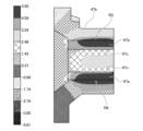
- FIG. 11 is a schematic diagram showing the simulation results of the stress generated in the tubular portion 47b of the main body portion according to Example 1.
- the concave groove 47c shown in Figure 11 corresponds to the convex portion of the boundary 46e described above, but since the change in the convex shape is gradual, the stress generated in the concave groove 47c is not large. Regions R3 and R4 where the stress is highest are the plane 47a that is in contact with the plane that is the second surface 46b of the sleeve 46, and the stress is easily dispersed.
- the stress generated in the regions R3 and R4 of the plane 47a corresponding to the second surface 46b is a maximum of approximately 5 MPa. Therefore, it can be seen that the stress generated in the regions R3 and R4 of the plane 47a is significantly lower than the stress generated in the regions R1 and R2 of the ridge 42c of the tubular portion 42b in the reference example. In this way, stress is less likely to concentrate in the groove 47c, and the stress is dispersed to the gently curved surface and plane 47a adjacent to the groove 47c, so that the portion of the rotating portion 22b to which the sleeve 46 is fixed is less likely to deform even if it is made of resin.
- the anti-rotation portion 46c of the sleeve 46 has a shape with four-fold symmetry when viewed from the direction along the rotation axis, but the anti-rotation portion may have n-fold symmetry (2 ⁇ n ⁇ 6). This allows the parts to which stress is applied to be arranged symmetrically, making it less likely that localized stress concentrations will occur.
- the sleeve 46 is symmetrical from top to bottom when the direction along the rotation axis is taken as the up-down direction. This prevents the sleeve 46 from being attached to the rotating part 22b upside down, improving workability during manufacturing.
- the sleeve 46 is a metal component that has been machined.
- the cutting oil used during the machining process can affect the properties of the resin. For example, even if the resin is easily deformed by cutting oil, the shape of the sleeve 46 that is fixed to the rotating part 22b has been designed to prevent a decrease in rotation accuracy due to deformation of the rotating part 22b.
- the sleeve 46 of Example 1 can reduce stress generated on the inner peripheral surface of the through hole 42a of the main body 42 while preventing the rotating reflector from rotating relative to the main body by devising a shape of the outer peripheral surface.
- the cross-sectional shape of the sleeve (a cross section perpendicular to the motor shaft) is uniform anywhere in the axial direction. Therefore, when an axial force is applied to the sleeve 46 fitted in the through hole 42a of the main body 42, there is no catch between the inner peripheral surface of the through hole 42a and the outer peripheral surface of the sleeve 46, and the contact area between them is smaller than that of the sleeve 44 of the reference example.
- the stress generated in the main body 42 is also reduced, making it easier for the sleeve to be displaced (easily removed) in the axial direction.
- Figures 12(a) to 12(c) are schematic diagrams for explaining the mechanism by which the sleeve is displaced within the through hole due to thermal cycles.
- a vehicle headlamp equipped with a rotating reflector 22 is located near the engine compartment and is used in a variety of environments. Therefore, the environmental temperature of the rotating reflector can vary from approximately -30°C to 90°C.
- the rotating reflector 22 has a resin body 42 and a brass sleeve 46, and as shown in Figure 12(a), the sleeve 46, which is the brass part, shrinks first due to the difference in thermal conductivity between the resin and brass. As a result, a gap G is generated between the sleeve 46 and the body 42.
- FIG. 13 is a perspective view of a sleeve according to Example 2.
- Fig. 14(a) is a side view of the sleeve shown in Fig. 13
- Fig. 14(b) is a top view of the sleeve shown in Fig. 13
- Fig. 14(c) is a cross-sectional view taken along CC of the sleeve shown in Fig. 14(b).
- the sleeve 48 according to Example 2 is the same as the sleeve 36 shown in Fig. 7.
- the sleeve 48 has a rotation prevention portion 48c formed on the outer circumferential surface 48d, the rotation prevention portion 48c including a first surface 48a and a second surface 48b that connects the first surfaces and has a larger radius of curvature than the first surface 48a.
- the rotation prevention portion 48c is configured so that the boundary 48e between the first surface 48a and the second surface 48b is convex toward the outside.
- the first surface 48a is an arc
- the second surface 48b is a flat surface.
- the rotation prevention portion 48c of the sleeve 48 according to the second embodiment includes two first surfaces 48a and two second surfaces 48b, but may be a rotation prevention portion configured by connecting both sides of one first surface 48a with one second surface 48b.
- the sleeve 48 in Example 2 has a height H1 of 4 to 8 mm, a height H2 of 2 to 5 mm, a diameter D1 of the hole 48f into which the motor shaft is inserted and fitted of 2 to 4 mm, a diameter D2 of the first surface 48a which is an arc of 5 to 8 mm, and a distance D3 between the two second surfaces 48b of 4 to 7.5 mm.
- the size of each part does not necessarily have to be within this range, and can be selected as appropriate within the range in which the object of the invention can be achieved.
- the outer peripheral surface 48d of the sleeve 48 is formed with a retaining portion having a recess 48g that is recessed toward the center of the hole 48f more than the anti-rotation portion 48c.
- the retaining portion of the sleeve 48 is formed by a step between the recess 48g and the first and second surfaces 48a and 48b. This makes it possible to suppress movement in the direction of the rotation axis even if a force is applied to the sleeve 48 in the direction of the rotation axis.
- the recess 48g is covered with the resin of the main body portion 42 as shown in FIG. 7. As a result, the resin covering the recess 48g functions as a retaining portion to prevent it from coming out.
- the number of blades 22a of the rotating reflector 22 in this embodiment is two. There are also two anti-rotation portions 48c. In this way, by making the number of blades 22a and the number of anti-rotation portions 48c the same, the rotation accuracy can be improved.
- the sleeve 50 shown in FIG. 15 has a first surface 50a and a second surface 50b that connects the first surfaces and has a larger radius of curvature than the first surface 50a.
- the anti-rotation portion 50c is formed on the outer circumferential surface 50d.
- the anti-rotation portion 50c is configured so that the boundary 50e between the first surface 50a and the second surface 50b is convex toward the outside.
- the first surface 50a is an arc
- the second surface 50b is a flat surface.
- the anti-rotation portion 50c of the sleeve 50 is provided in two stages spaced apart in the axial direction of the hole 50f.
- a recess 50g is formed that is recessed toward the center of the hole 50f more than the anti-rotation portion 50c.
- This recess 50g is covered with the resin of the main body 42, and the resin covering the recess 48g functions as a locking portion to prevent the sleeve 50 from coming off.
Landscapes
- Engineering & Computer Science (AREA)
- General Engineering & Computer Science (AREA)
- Non-Portable Lighting Devices Or Systems Thereof (AREA)
Abstract
所望の配光パターンを形成可能な新たな回転リフレクタを提供する。回転リフレクタは、回転部と、回転部の周囲に設けられ、反射面として機能するブレードを有する樹脂製の本体部と、を備える。回転部は、モータの回転軸が圧入されるスリーブ46が固定されている。スリーブ46は、複数の第1の面46aと、第1の面同士をつなぎ、第1の面よりも曲率半径が大きな第2の面46bと、を含む回り止め部46cが外周面46dに形成されている。回り止め部46cは、第1の面46aと第2の面46bとの境界46eが外側に向かって凸となるように構成されている。
Description
本発明は、回転リフレクタに関する。
従来、光源から出射した光を反射しながら回転軸を中心に一方向に回転する回転リフレクタを備えた光学ユニットが考案されている(特許文献1参照)。この光学ユニットが備える回転リフレクタは、回転しながら反射した光源の光が所望の配光パターンを形成するよう反射面が設けられている。
前述の回転リフレクタは、回転中心となる回転部に、スリーブがインサート成形により固定されている。スリーブは、モータの回転軸が挿入され嵌合する穴が形成された円筒状の部材である。また、スリーブは、回転リフレクタ本体に対して外れたり空回りしたりしないように回転部に固定する必要がある。そこで、スリーブの外周にローレットを形成したり外周の軸方向に複数の溝(スプライン)を形成したりすることで回転部に強固に固定する方法が考案されている。
しかしながら、ローレットやスプラインは凹凸による形状変化が大きい。そのため、回転リフレクタの回転時に、スリーブと回転リフレクタ本体との接合部で局所的な応力集中が発生することがある。その場合、回転リフレクタの中心部で変形が生じることで、反射面の正常な位置からの変位や回転軸の偏心が生じる可能性があり、配光パターンを高精度で形成することを妨げることになる。
本発明はこうした状況に鑑みてなされたものであり、その目的とするところの一つは、安定して所望の配光パターンを形成可能な新たな回転リフレクタを提供することにある。
上記課題を解決するために、本発明のある態様の回転リフレクタは、回転部と、回転部の周囲に設けられ、反射面として機能するブレードを有する樹脂製の本体部と、を備える回転リフレクタであって、回転部は、モータの回転軸が圧入されるスリーブが固定されており、スリーブは、複数の第1の面と、第1の面同士をつなぎ、第1の面よりも曲率半径が大きな第2の面と、を含む回り止め部が外周面に形成されており、回り止め部は、第1の面と第2の面との境界が外側に向かって凸となるように構成されている。
この態様によると、回り止め部の境界が外側に向かって凸となっている。一方、スリーブが固定される回転部の内周面は、前述の凸の部分に対応するように凹部が形成されている。凹部には応力が集中しにくく、凹部に隣接するなだらかな曲面や平面に応力が分散するため、回転部のスリーブが固定される部分が樹脂製であっても変形しにくくなる。
回り止め部は、回転軸に沿った方向から見た場合、n(2≦n≦6)回対称の形状であってもよい。これにより、応力がかかる部分が対称的に配置されることで、局所的な応力集中が発生しにくくなる。
第1の面は円弧であり、第2の面は平面であってもよい。これにより、回転リフレクタが回転する場合、スリーブの第2の面が接する回転部の内周面で応力を分散できる。
外周面は、回転軸に沿った方向から見た場合、回り止め部よりも中心に向かって凹んだ凹部を有する抜け止め部が形成されていてもよい。これにより、スリーブに回転軸方向の力がかかっても回転軸方向への移動を抑制できる。
スリーブは、回転軸に沿った方向を上下方向とした場合、上下対称形状であってもよい。これにより、スリーブの上下を間違えて回転部に固定することがなくなり、製造時の作業性を向上できる。
凹部は、本体部の樹脂で被覆されていてもよい。これにより、凹部を被覆した樹脂が抜け止めの係止部として機能する。
回転部は、本体部とともにインサート成形された樹脂によりスリーブを固定していてもよい。これにより、スリーブが固定された回転リフレクタを簡易な工程で製造できる。
スリーブは、切削加工された金属部材であってもよい。切削加工の際の切削油は樹脂の特性に影響を与える場合がある。例えば、切削油によって変形しやすくなる樹脂であっても、回転部に固定されるスリーブの形状が工夫されているため、回転部が変形することによる回転精度の低下を抑制できる。
ブレードは、n個あってもよい。これにより、ブレードの数と回り止め部とを同数とすることで回転精度を向上できる。
以上の構成要素の任意の組合せ、本発明の表現を製造方法、灯具や照明などの装置、発光モジュール、光源などの間で変換したものもまた、本発明の態様として有効である。
本発明によれば、所望の配光パターンを形成可能な新たな回転リフレクタを提供できる。
[規則91に基づく訂正 08.07.2024]
本実施の形態に係る車両用前照灯の水平断面概要図である。
本実施の形態に係る車両用前照灯の正面図である。
本実施の形態に係る光学ユニットの要部を示す斜視図である。
本実施の形態に係る回転リフレクタの斜視図である。
本実施の形態に係る回転リフレクタの正面図である。
図5に示す回転リフレクタをA方向から見た側面図である。
図5に示す回転リフレクタのB-B断面図である。
図8(a)は、参考例に係るスリーブの斜視図、図8(b)は、参考例に係るスリーブの上面図である。
参考例に係る本体部の筒部に生じる応力のシミュレーション結果を示す模式図である。
図10(a)は、実施例1に係るスリーブの斜視図、図10(b)は、実施例1に係るスリーブの上面図である。
実施例1に係る本体部の筒部に生じる応力のシミュレーション結果を示す模式図である。
図12(a)~図12(c)は、熱サイクルによりスリーブが貫通孔内で変位するメカニズムを説明するための模式図である。
実施例2に係るスリーブの斜視図である。
図14(a)は、図13に示すスリーブの側面図、図14(b)は、図13に示すスリーブの上面図、図14(c)は、図14(b)に示すスリーブのC-C断面図である。
実施例3に係るスリーブの斜視図である。
以下、本発明を実施の形態をもとに図面を参照しながら説明する。各図面に示される同一または同等の構成要素、部材、処理には、同一の符号を付するものとし、適宜重複した説明は省略する。また、実施の形態は、発明を限定するものではなく例示であって、実施の形態に記述される全ての特徴やその組合せは、必ずしも発明の本質的なものであるとは限らない。
本実施の形態に係る回転リフレクタは、光源から出射した光を反射しながら回転するものであり、種々の車両用灯具に用いることができる。はじめに、後述する実施の形態に係る回転リフレクタを搭載可能な車両用前照灯の概略について説明する。
(車両用前照灯)
図1は、本実施の形態に係る車両用前照灯の水平断面概要図である。図2は、本実施の形態に係る車両用前照灯の正面図である。なお、図2においては、一部の部品を省略してある。
図1は、本実施の形態に係る車両用前照灯の水平断面概要図である。図2は、本実施の形態に係る車両用前照灯の正面図である。なお、図2においては、一部の部品を省略してある。
本実施の形態に係る車両用前照灯10は、自動車の前端部の右側に搭載される右側前照灯であり、左側に搭載される前照灯と左右対称である以外は同じ構造である。そのため、以下では、右側の車両用前照灯10について詳述し、左側の車両用前照灯については説明を省略する。
図1に示すように、車両用前照灯10は、前方に向かって開口した凹部を有するランプボディ12を備えている。ランプボディ12は、その前面開口が透明な前面カバー14によって覆われて灯室16が形成されている。灯室16は、一つの光学ユニット18が収容される空間として機能する。光学ユニット18は、可変ハイビームを照射できるように構成されたランプユニットである。可変ハイビームとは、ハイビーム用の配光パターンの形状を変化させるように制御されているものをいい、例えば、配光パターンの一部に非照射領域(遮光部)を生じさせることができる。
本実施の形態に係る光学ユニット18は、第1の光源20と、第1の光源20から出射した第1の光L1の光路を変化させて回転リフレクタ22のブレード22aに向かわせる1次光学系(光学部材)としての集光用レンズ24と、第1の光L1を反射しながら回転軸Rを中心に回転する回転リフレクタ22と、回転リフレクタ22で反射された第1の光L1を光学ユニットの光照射方向(図1右方向)に投影する投影レンズとしての凸レンズ26と、第1の光源20と凸レンズ26との間に配置された第2の光源28と、第2の光源28から出射した第2の光L2の光路を変化させて凸レンズ26に向かわせる1次光学系(光学部材)としての拡散用レンズ30と、第1の光源20及び第2の光源28を搭載したヒートシンク32と、を備える。
各光源には、LED、EL、LDなどの半導体発光素子が用いられる。本実施の形態に係る第1の光源20は、回路基板33上に、複数のLED20aがアレイ状に配置されている。各LED20aは個別に点消灯可能に構成されている。
本実施の形態に係る第2の光源28は、2つのLED28aがアレイ状に水平方向に並んで配置されており、各LED28aは個別に点消灯可能に構成されている。また、第2の光源28は、第2の光L2が回転リフレクタ22で反射されずに凸レンズ26に入射するように配置されている。これにより、第2の光源28から出射した第2の光L2は、回転リフレクタ22で反射されることを考慮せずに光学特性を選択できる。そのため、例えば、第2の光源28から出射した光を拡散用レンズ30で拡散させてから凸レンズ26に入射させることで、より広い範囲を照射できるため、第2の光源28を車両外側の領域を照射する光源として用いることができる。
回転リフレクタ22は、モータ34などの駆動源により回転軸Rを中心に一方向に回転する。また、回転リフレクタ22は、形状の同じ2枚のブレード22aが筒状の回転部22bの周囲に設けられている。ブレード22aは、第1の光源20から出射した光を回転しながら反射した光で前方を走査し、所望の配光パターンを形成するように構成された反射面として機能する。
回転リフレクタ22の回転軸Rは、光軸Axに対して斜めになっており、光軸Axと第1の光源20とを含む平面内に設けられている。換言すると、回転軸Rは、回転によって左右方向に走査するLED20aの光(照射ビーム)の走査平面に略平行に設けられている。これにより、光学ユニットの薄型化が図られる。ここで、走査平面とは、例えば、走査光であるLED20aの光の軌跡を連続的につなげることで形成される扇形の平面ととらえることができる。
凸レンズ26の形状は、要求される配光パターンや照度分布などの配光特性に応じて適宜選択すればよいが、非球面レンズや自由曲面レンズを用いることも可能である。例えば、本実施の形態に係る凸レンズ26は、各光源や回転リフレクタ22の配置を工夫することで、外周の一部が鉛直方向に切り欠かれた切り欠き部26aを形成することが可能となっている。そのため、光学ユニット18の車幅方向の大きさを抑えることができる。
また、切り欠き部26aが存在することで、回転リフレクタ22のブレード22aが凸レンズ26に干渉しにくくなり、凸レンズ26と回転リフレクタ22とを近づけることができる。また、前方から車両用前照灯10を見た場合に、凸レンズ26の外周に非円形(直線)の部分が形成されていることで、車両の正面から見て曲線と直線を組み合わせた外形のレンズを有する斬新な意匠の車両用前照灯を実現できる。
(光学ユニット)
図3は、本実施の形態に係る光学ユニットの要部を示す斜視図である。なお、図3では、光学ユニット18を構成する部品のうち、主として第1の光源20、回転リフレクタ22及び凸レンズ26を示しており、説明の便宜上一部の部品の図示を省略している。
図3は、本実施の形態に係る光学ユニットの要部を示す斜視図である。なお、図3では、光学ユニット18を構成する部品のうち、主として第1の光源20、回転リフレクタ22及び凸レンズ26を示しており、説明の便宜上一部の部品の図示を省略している。
図3に示すように、光学ユニット18は、水平方向に向かってライン状に配列された複数のLED20aからなる第1の光源20と、第1の光源20から出射した光を回転リフレクタ22で反射された光を光学ユニットの光照射方向(光軸Ax)に投影する凸レンズ26を備えている。回転リフレクタ22は、回転軸Rが光照射方向(光軸Ax)に対して斜めにかつ水平方向に延びるように配置されている。また、第1の光源20は、複数のLED20aのそれぞれの発光面が反射面に対して斜めとなるように配置されている。
ブレード22aの反射面22dは、回転軸Rを中心とする周方向に向かうにつれて、光軸Axと該反射面とが成す角が変化するように捩られた形状を有している。なお、反射面のより詳細な形状は後述する。
(回転リフレクタ)
次に、本実施の形態に係る回転リフレクタ22の構造の詳細について説明する。図4は、本実施の形態に係る回転リフレクタの斜視図である。図5は、本実施の形態に係る回転リフレクタの正面図である。図6は、図5に示す回転リフレクタをA方向から見た側面図である。図7は、図5に示す回転リフレクタのB-B断面図である。
次に、本実施の形態に係る回転リフレクタ22の構造の詳細について説明する。図4は、本実施の形態に係る回転リフレクタの斜視図である。図5は、本実施の形態に係る回転リフレクタの正面図である。図6は、図5に示す回転リフレクタをA方向から見た側面図である。図7は、図5に示す回転リフレクタのB-B断面図である。
回転リフレクタ22は、回転部22bと、回転部22bの周囲に設けられ、反射面として機能する複数(2枚)のブレード22aと、を有する樹脂製の部品である。ブレード22aは円弧形状であり、隣接するブレード22aの外周部が連結部22cで接続されることで環状になっている。これにより、回転リフレクタ22が高速回転(例えば50~240回転/s)しても、回転リフレクタ22が撓みにくくなる。
回転部22bの中心には、回転リフレクタ22の回転軸が挿入され嵌合する穴36aが形成された円筒状のスリーブ36がインサート成形により固定されている。また、回転部22bの外周部であって、ブレード22aの内側に形成されている環状の溝38には、金型のゲート位置に対応する跡として2箇所の凹部40が形成されている。
なお、図4乃至図7に示す回転リフレクタ22は、右側前照灯用の車両用前照灯10に用いられるものであり、反射面22dの正面視において反時計回りに回転する。また、ブレード22aの反射面22dは、図4乃至図7に示すように、外周部の軸方向の高さ(ブレードの厚み方向)が正面視で反時計回りに向かって徐々に高くなるように構成されている。反対に、反射面22dは、回転部22bに近い内周部の軸方向の高さが反時計回りに向かって徐々に低くなるように構成されている。
また、反射面22dは、外周部のうち軸方向の高さが低い方の端部22eから中心(回転部22b)に向かって徐々に高くなるように構成されている。反対に、反射面22dは、外周部のうち軸方向の高さが高い方の端部22fから中心に向かって徐々に低くなるように構成されている。
このように、本実施の形態に係る回転リフレクタ22は、回転部22bと、回転部の周囲に設けられ、反射面として機能するブレード22aを有する本体部42と、を備える。本体部42は、スリーブ36が固定される貫通孔42aが形成されている筒部42bからブレード22aまでの樹脂製の一体部品である。筒部42bは、モータ34の回転軸Rが圧入される金属製のスリーブ36が固定されている。つまり、回転部22bは、本体部42とともにインサート成形された樹脂によりスリーブ36を固定している。これにより、スリーブ36が固定された回転リフレクタ22を簡易な工程で製造できる。
スリーブ36は、筒部42bに対して空回りしないように外周の少なくとも一部が非円形の形状(すべり止め形状)となっている。図8(a)は、参考例に係るスリーブの斜視図、図8(b)は、参考例に係るスリーブの上面図である。図8(a)、図8(b)に示すスリーブ44は、外周面44aの周方向に等間隔の凹溝44b(凸条44c)が形成されている。参考例に係るスリーブ44は、軸方向に沿って形成されている凹溝44bが22個設けられている。
スリーブ44が金属製(具体的には例えば真ちゅう製)の場合、回転リフレクタ22の樹脂製の本体部42より強度が高いため、回転リフレクタ22が高速回転している際にスリーブの凹溝44b(凸条44c)によって、筒部42bの内周面に局所的な応力集中が発生する。
図9は、参考例に係る本体部42の筒部42bに生じる応力のシミュレーション結果を示す模式図である。図9に示す筒部42bの内周面には凸条42cと凹溝42dが交互に形成されている。凸条42cは、スリーブ44の凹溝44bに対応する形状であり、凹溝42dは、スリーブ44の凸条44cに対応する形状である。図9に示すシミュレーションでは、凸条42cの一部の領域R1や領域R2に発生する応力が15MPa程度である。そのため、樹脂製の本体部42の一部が変形することでブレード22aが変形したり、回転リフレクタ22が偏心したりするおそれがあり、高精度な配光パターンの形成に支障が生じる可能性がある。
そこで、本願発明者はスリーブの外周形状を工夫することとした。図10(a)は、実施例1に係るスリーブの斜視図、図10(b)は、実施例1に係るスリーブの上面図である。スリーブ46は、複数の第1の面46aと、第1の面同士をつなぎ、第1の面46aよりも曲率半径が大きな第2の面46bと、を含む回り止め部46cが外周面46dに形成されている。回り止め部46cは、第1の面46aと第2の面46bとの境界46eが外側に向かって凸となるように構成されている。第1の面46aは円弧であり、第2の面46bは平面である。
このように、実施例1に係るスリーブ46は、回り止め部46cの境界46eが外側に向かって凸となっている一方、スリーブ46が固定される回転部の内周面は、前述の凸の部分に対応するように凹部が形成されている。図11は、実施例1に係る本体部の筒部47bに生じる応力のシミュレーション結果を示す模式図である。図11に示す凹溝47cは、前述の境界46eの凸の部分に対応するが凸の形状変化がなだらかなため、凹溝47cに発生する応力が大きくない。応力が最も高い領域R3や領域R4は、スリーブ46の第2の面46bである平面が接する平面47aであり、応力が分散されやすい。
図11に示すシミュレーションでは、第2の面46bに対応する平面47aの一部の領域R3や領域R4に発生する応力が最大で5MPa程度である。そのため、平面47aの一部の領域R3や領域R4に発生する応力は、参考例に係る筒部42bの凸条42cの一部の領域R1や領域R2に発生する応力よりもかなり低いことがわかる。このように、凹溝47cには応力が集中しにくく、凹溝47cに隣接するなだらかな曲面や平面47aに応力が分散するため、回転部22bのスリーブ46が固定される部分が樹脂製であっても変形しにくくなる。
なお、スリーブ46の回り止め部46cは、回転軸に沿った方向から見た場合、4回対称の形状であるが、回り止め部はn(2≦n≦6)回対称であってもよい。これにより、応力がかかる部分が対称的に配置されることで、局所的な応力集中が発生しにくくなる。
また、スリーブ46は、回転軸に沿った方向を上下方向とした場合、上下対称形状である。これにより、スリーブ46の上下を間違えて回転部22bに固定することがなくなり、製造時の作業性を向上できる。
また、スリーブ46は、切削加工された金属部材である。切削加工の際の切削油は樹脂の特性に影響を与える場合がある。例えば、切削油によって変形しやすくなる樹脂であっても、回転部22bに固定されるスリーブ46の形状が工夫されているため、回転部22bが変形することによる回転精度の低下を抑制できる。
実施例1に係るスリーブ46は、外周面の形状を工夫することで回転リフレクタの本体部に対する回り止めを実現しつつ、本体部42の貫通孔42aの内周面で発生する応力を低減できる。しかしながら、スリーブの横断面形状(モータの軸と直交する断面)は軸方向のどこであっても均一である。そのため、本体部42の貫通孔42aに嵌まっているスリーブ46に軸方向の力がかかった場合、貫通孔42aの内周面とスリーブ46の外周面との間に引っかかりがなく、互いの接触面積も参考例に係るスリーブ44と比較して小さくなる。加えて、本体部42に生じる応力も低減されているため、スリーブが軸方向に変位しやすく(抜けやすく)なる。
図12(a)~図12(c)は、熱サイクルによりスリーブが貫通孔内で変位するメカニズムを説明するための模式図である。回転リフレクタ22を備える車両用前照灯は、エンジンルームの近くにあり、また使用される環境も様々である。そのため、回転リフレクタの環境温度は-30℃から90℃程度まで変化しうる。回転リフレクタ22は、樹脂製の本体部42と真ちゅう製のスリーブ46とを有しており、図12(a)に示すように、樹脂と真ちゅうの熱伝導率の差から真ちゅう部分であるスリーブ46が先に収縮する。そのため、スリーブ46と本体部42との間に隙間Gが発生する。
その後、樹脂の収縮が追従すると、図12(b)に示すように、本体部42の筒部42bからスリーブ46の外周面に応力がかかるが、この応力は均一ではない。そのため、熱サイクルが繰り返されることで、図12(c)に示すように、本体部42の筒部42bからスリーブ46が徐々に浮き上がる可能性がある。
[規則91に基づく訂正 08.07.2024]
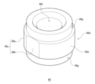
そこで、この点を考慮して外周面の形状を工夫した新たなスリーブを考案した。図13は、実施例2に係るスリーブの斜視図である。図14(a)は、図13に示すスリーブの側面図、図14(b)は、図13に示すスリーブの上面図、図14(c)は、図14(b)に示すスリーブのC-C断面図である。なお、実施例2に係るスリーブ48は、図7に示すスリーブ36と同じである。
そこで、この点を考慮して外周面の形状を工夫した新たなスリーブを考案した。図13は、実施例2に係るスリーブの斜視図である。図14(a)は、図13に示すスリーブの側面図、図14(b)は、図13に示すスリーブの上面図、図14(c)は、図14(b)に示すスリーブのC-C断面図である。なお、実施例2に係るスリーブ48は、図7に示すスリーブ36と同じである。
スリーブ48は、第1の面48aと、第1の面同士をつなぎ、第1の面48aよりも曲率半径が大きな第2の面48bと、を含む回り止め部48cが外周面48dに形成されている。回り止め部48cは、第1の面48aと第2の面48bとの境界48eが外側に向かって凸となるように構成されている。第1の面48aは円弧であり、第2の面48bは平面である。なお、実施例2に係るスリーブ48の回り止め部48cは、2つの第1の面48aと2つの第2の面48bとを含んでいるが、一つの第1の面48aの両側を一つの第2の面48bでつなぐことで構成された回り止め部であってもよい。
実施例2に係るスリーブ48は、高さH1が4~8mm、高さH2が2~5mm、モータの回転軸が挿入され嵌合する穴48fの直径D1が2~4mm、円弧である第1の面48aの直径D2が5~8mm、2つの第2の面48b同士の距離D3が4~7.5mmの範囲である。なお、各部の大きさは必ずしもこの範囲である必要はなく、発明の目的を達成できる範囲で適宜選択することができる。
また、スリーブ48の外周面48dは、回転軸に沿った方向から見た場合、回り止め部48cよりも穴48fの中心に向かって凹んだ凹部48gを有する抜け止め部が形成されている。スリーブ48の抜け止め部は、凹部48gと、第1の面48a及び第2の面48bとの段差によって構成されている。これにより、スリーブ48に回転軸方向の力がかかっても回転軸方向への移動を抑制できる。凹部48gは、図7に示すように、本体部42の樹脂で被覆されるものである。これにより、凹部48gを被覆した樹脂が抜け止めの係止部として機能する。
本実施の形態に係る回転リフレクタ22のブレード22aの数は2個である。また、回り止め部48cも2個ある。このように、ブレード22aの数と回り止め部48cの数とを同数とすることで回転精度を向上できる。
図15は、実施例3に係るスリーブの斜視図である。図15に示すスリーブ50は、第1の面50aと、第1の面同士をつなぎ、第1の面50aよりも曲率半径が大きな第2の面50bと、を含む回り止め部50cが外周面50dに形成されている。回り止め部50cは、第1の面50aと第2の面50bとの境界50eが外側に向かって凸となるように構成されている。第1の面50aは円弧であり、第2の面50bは平面である。また、スリーブ50の回り止め部50cは、穴50fの軸方向に離れて2段設けられている。2段の回り止め部50cの間には、回り止め部50cよりも穴50fの中心に向かって凹んだ凹部50gが形成されている。この凹部50gが本体部42の樹脂で被覆されることで、凹部48gを被覆した樹脂が抜け止めの係止部として機能する。
以上、本発明を上述の実施の形態を参照して説明したが、本発明は上述の実施の形態に限定されるものではなく、実施の形態の構成を適宜組み合わせたものや置換したものについても本発明に含まれるものである。また、当業者の知識に基づいて実施の形態における組合せや処理の順番を適宜組み替えることや各種の設計変更等の変形を実施の形態に対して加えることも可能であり、そのような変形が加えられた実施の形態も本発明の範囲に含まれうる。
本国際出願は、2023年6月27日に出願された日本国特許出願である特願2023-105418号に基づく優先権を主張するものであり、当該日本国特許出願である特願2023-105418号の全内容は、本国際出願に援用される。
本発明の特定の実施の形態についての上記説明は、例示を目的として提示したものである。それらは、網羅的であったり、記載した形態そのままに本発明を制限したりすることを意図したものではない。数多くの変形や変更が、上記の記載内容に照らして可能であることは当業者に自明である。
10 車両用前照灯、 18 光学ユニット、 22 回転リフレクタ、 22a ブレード、 22b 回転部、 22c 連結部、 22d 反射面、 34 モータ、 36 スリーブ、 36a 穴、 38 溝、 40 凹部、 42 本体部、 42a 貫通孔、 42b 筒部、 46 スリーブ、 46a 第1の面、 46b 第2の面、 46c 回り止め部、 46d 外周面、 46e 境界、 47a 平面、 47b 筒部、 47c 凹溝、 R 回転軸。
Claims (9)
- 回転部と、
前記回転部の周囲に設けられ、反射面として機能するブレードを有する樹脂製の本体部と、を備える回転リフレクタであって、
前記回転部は、モータの回転軸が圧入されるスリーブが固定されており、
前記スリーブは、複数の第1の面と、前記第1の面同士をつなぎ、前記第1の面よりも曲率半径が大きな第2の面と、を含む回り止め部が外周面に形成されており、
前記回り止め部は、前記第1の面と前記第2の面との境界が外側に向かって凸となるように構成されていることを特徴とする回転リフレクタ。 - 前記回り止め部は、回転軸に沿った方向から見た場合、n(2≦n≦6)回対称の形状であることを特徴とする請求項1に記載の回転リフレクタ。
- 前記第1の面は円弧であり、前記第2の面は平面であることを特徴とする請求項1又は2に記載の回転リフレクタ。
- 前記外周面は、回転軸に沿った方向から見た場合、前記回り止め部よりも中心に向かって凹んだ凹部を有する抜け止め部が形成されていることを特徴とする請求項1又は2に記載の回転リフレクタ。
- 前記スリーブは、回転軸に沿った方向を上下方向とした場合、上下対称形状であることを特徴とする請求項4に記載の回転リフレクタ。
- 前記凹部は、前記本体部の樹脂で被覆されていることを特徴とする請求項4に記載の回転リフレクタ。
- 前記回転部は、前記本体部とともにインサート成形された樹脂により前記スリーブを固定していることを特徴とする請求項6に記載の回転リフレクタ。
- 前記スリーブは、切削加工された金属部材であることを特徴とする請求項1又は2に記載の回転リフレクタ。
- 前記ブレードは、n個あることを特徴とする請求項2に記載の回転リフレクタ。
Applications Claiming Priority (2)
| Application Number | Priority Date | Filing Date | Title |
|---|---|---|---|
| JP2023-105418 | 2023-06-27 | ||
| JP2023105418A JP2025005276A (ja) | 2023-06-27 | 2023-06-27 | 回転リフレクタ |
Publications (1)
| Publication Number | Publication Date |
|---|---|
| WO2025004874A1 true WO2025004874A1 (ja) | 2025-01-02 |
Family
ID=93938981
Family Applications (1)
| Application Number | Title | Priority Date | Filing Date |
|---|---|---|---|
| PCT/JP2024/021833 Ceased WO2025004874A1 (ja) | 2023-06-27 | 2024-06-17 | 回転リフレクタ |
Country Status (2)
| Country | Link |
|---|---|
| JP (1) | JP2025005276A (ja) |
| WO (1) | WO2025004874A1 (ja) |
Citations (2)
| Publication number | Priority date | Publication date | Assignee | Title |
|---|---|---|---|---|
| WO2020008034A1 (de) * | 2018-07-06 | 2020-01-09 | Wobben Properties Gmbh | Verfahren zum steuern eines windparks |
| CN212454952U (zh) * | 2020-05-26 | 2021-02-02 | 广东朗迪格林特电器有限公司 | 一种轴流风叶 |
-
2023
- 2023-06-27 JP JP2023105418A patent/JP2025005276A/ja active Pending
-
2024
- 2024-06-17 WO PCT/JP2024/021833 patent/WO2025004874A1/ja not_active Ceased
Patent Citations (2)
| Publication number | Priority date | Publication date | Assignee | Title |
|---|---|---|---|---|
| WO2020008034A1 (de) * | 2018-07-06 | 2020-01-09 | Wobben Properties Gmbh | Verfahren zum steuern eines windparks |
| CN212454952U (zh) * | 2020-05-26 | 2021-02-02 | 广东朗迪格林特电器有限公司 | 一种轴流风叶 |
Also Published As
| Publication number | Publication date |
|---|---|
| JP2025005276A (ja) | 2025-01-16 |
Similar Documents
| Publication | Publication Date | Title |
|---|---|---|
| JP5393018B2 (ja) | 高効率自動車用led光学装置 | |
| JP4825140B2 (ja) | 車両用灯具 | |
| JP7333169B2 (ja) | 車両用灯具 | |
| JP6441823B2 (ja) | 車両用灯具 | |
| US7270454B2 (en) | Vehicular lamp | |
| JP5748531B2 (ja) | 車両用灯具 | |
| US20150009679A1 (en) | Beam-control member and illumination device | |
| WO2020241424A1 (ja) | 車両用灯具 | |
| JP7564915B2 (ja) | 車両用灯具および回転リフレクタ | |
| JP7355754B2 (ja) | 回転リフレクタの製造方法および回転リフレクタ | |
| JP2024099853A (ja) | 光学ユニットおよび反射面決定方法 | |
| WO2017179465A1 (ja) | 発光ユニットおよび車両用灯具 | |
| US6200006B1 (en) | Vehicle Lamp | |
| WO2025004874A1 (ja) | 回転リフレクタ | |
| WO2016181905A1 (ja) | 照明装置及び光学部材 | |
| JP2007265688A (ja) | コリメーションレンズ及びこれを用いた照明装置 | |
| JP2013037918A (ja) | 照明装置 | |
| JP6830850B2 (ja) | 車両用灯具 | |
| WO2016175214A1 (ja) | 照明装置及び光学部材 | |
| JP2006147399A (ja) | 車両用灯具 | |
| CN210860955U (zh) | 旋转反射器 | |
| JP5143685B2 (ja) | 照明装置 | |
| WO2025187611A1 (ja) | ナット部材及び光軸調整機構 | |
| JP7300598B2 (ja) | 照明器具用レンズおよび照明器具 | |
| JP2006286262A (ja) | 車両用ランプ |
Legal Events
| Date | Code | Title | Description |
|---|---|---|---|
| 121 | Ep: the epo has been informed by wipo that ep was designated in this application |
Ref document number: 24831737 Country of ref document: EP Kind code of ref document: A1 |
|
| NENP | Non-entry into the national phase |
Ref country code: DE |