WO2025004774A1 - 電気接続箱 - Google Patents
電気接続箱 Download PDFInfo
- Publication number
- WO2025004774A1 WO2025004774A1 PCT/JP2024/021003 JP2024021003W WO2025004774A1 WO 2025004774 A1 WO2025004774 A1 WO 2025004774A1 JP 2024021003 W JP2024021003 W JP 2024021003W WO 2025004774 A1 WO2025004774 A1 WO 2025004774A1
- Authority
- WO
- WIPO (PCT)
- Prior art keywords
- metal plate
- base member
- tapping screw
- junction box
- circuit components
- Prior art date
- Legal status (The legal status is an assumption and is not a legal conclusion. Google has not performed a legal analysis and makes no representation as to the accuracy of the status listed.)
- Ceased
Links
Images

Classifications
-
- H—ELECTRICITY
- H02—GENERATION; CONVERSION OR DISTRIBUTION OF ELECTRIC POWER
- H02G—INSTALLATION OF ELECTRIC CABLES OR LINES, OR OF COMBINED OPTICAL AND ELECTRIC CABLES OR LINES
- H02G3/00—Installations of electric cables or lines or protective tubing therefor in or on buildings, equivalent structures or vehicles
- H02G3/02—Details
- H02G3/08—Distribution boxes; Connection or junction boxes
- H02G3/16—Distribution boxes; Connection or junction boxes structurally associated with support for line-connecting terminals within the box
-
- H—ELECTRICITY
- H05—ELECTRIC TECHNIQUES NOT OTHERWISE PROVIDED FOR
- H05K—PRINTED CIRCUITS; CASINGS OR CONSTRUCTIONAL DETAILS OF ELECTRIC APPARATUS; MANUFACTURE OF ASSEMBLAGES OF ELECTRICAL COMPONENTS
- H05K7/00—Constructional details common to different types of electric apparatus
- H05K7/20—Modifications to facilitate cooling, ventilating, or heating
-
- Y—GENERAL TAGGING OF NEW TECHNOLOGICAL DEVELOPMENTS; GENERAL TAGGING OF CROSS-SECTIONAL TECHNOLOGIES SPANNING OVER SEVERAL SECTIONS OF THE IPC; TECHNICAL SUBJECTS COVERED BY FORMER USPC CROSS-REFERENCE ART COLLECTIONS [XRACs] AND DIGESTS
- Y02—TECHNOLOGIES OR APPLICATIONS FOR MITIGATION OR ADAPTATION AGAINST CLIMATE CHANGE
- Y02E—REDUCTION OF GREENHOUSE GAS [GHG] EMISSIONS, RELATED TO ENERGY GENERATION, TRANSMISSION OR DISTRIBUTION
- Y02E60/00—Enabling technologies; Technologies with a potential or indirect contribution to GHG emissions mitigation
- Y02E60/10—Energy storage using batteries
Definitions
- This disclosure relates to an electrical junction box.
- an electrical junction box has been provided in, for example, a battery pack of a vehicle (see, for example, Patent Document 1).
- the battery pack includes a battery pack case, an electrical junction box, and multiple battery cells.
- the electrical junction box is housed in the battery pack case together with the multiple battery cells.
- the electrical junction box includes, for example, a case and electrical circuit components arranged on a base member that forms the bottom surface of the case.
- the electrical circuit components are connected to the multiple battery cells.
- the electrical circuit components include, for example, multiple relays, fuses, bus bars, etc.
- the electrical circuit components realize optimal input and output by monitoring the current value, temperature, etc. of the battery cells.
- bus bars which are metal plates, rather than thin wires, because they handle large currents.
- multiple metal plates are stacked and electrically connected.
- these multiple metal plates are generally firmly fastened together with nuts and bolts to reduce contact resistance and ensure a stable connection.
- nuts and bolts there is a problem in that the number of parts increases because many sets of nuts and bolts are required.
- the purpose of this disclosure is to provide an electrical connection box that reduces the number of parts.
- the electrical connection box disclosed herein comprises a plate-shaped base member and an electrical circuit component arranged on the base member, the electrical circuit component being an electrical connection box including a plurality of metal plates that are stacked and electrically connected, and is provided with a tapping screw capable of fixing the plurality of metal plates while forming a female thread in at least one of the plurality of metal plates.
- the electrical connection box disclosed herein can reduce the number of parts.
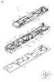
- FIG. 1 is a perspective view of an electrical junction box according to an embodiment.
- FIG. 2 is an exploded perspective view of the electrical junction box according to the embodiment.
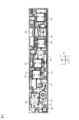
- FIG. 3 is a plan view of a first circuit unit and a heat dissipating metal plate according to an embodiment.
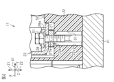
- FIG. 4 is a cross-sectional view taken along line 4-4 of FIG.
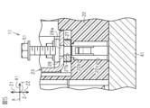
- FIG. 5 is a partial cross-sectional view of an electrical junction box according to an embodiment at a pre-manufacturing stage.
- the electrical connection box of the present disclosure comprises: [1] An electrical junction box comprising a plate-shaped base member and an electrical circuit component arranged on the base member, the electrical circuit component including a plurality of metal plates which are stacked and electrically connected, and a tapping screw capable of fixing the plurality of metal plates while forming a female thread in at least one of the plurality of metal plates.
- a tapping screw is provided that can fix multiple metal plates while forming a female thread in at least one of the multiple metal plates that are stacked and electrically connected, eliminating the need for nuts and the need to form a female thread in advance. This makes it possible to reduce the number of parts while suppressing an increase in processing man-hours.
- the base member may have a partition that separates the space in which shavings are generated by the tapping screw from the space in which other electrical circuit components are arranged.
- the base member has a partition that separates the space where shavings are generated by the tapping screw from the space where other electrical circuit components are arranged, making it possible to prevent the shavings from coming into contact with other electrical circuit components. This makes it possible to prevent, for example, other electrical circuit components from being unintentionally electrically connected to each other.
- a closing portion may be provided that closes a space in which shavings are generated by the tapping screw together with the partition portion.
- the electrical connection box is provided with a partition portion and a blocking portion that blocks the space in which shavings are generated by the tapping screw, thereby, for example, preventing shavings generated by the tapping screw from scattering outside the blocked space.
- the blocking portion may be a heat dissipating metal plate attached under the base member. According to this configuration, since the blocking portion is a heat dissipating metal plate attached under the base member, it is possible to prevent the shavings from scattering outside the blocked space while improving heat dissipation. In this way, by giving the heat dissipating metal plate, which has the function of improving heat dissipation, the function of preventing the shavings from scattering, it is possible to reduce the number of parts compared to when each is a separate member.
- the plurality of metal plates may include a first metal plate having a female thread hole in which the female thread is formed by the tapping screw, and a second metal plate having an insertion hole through which the tapping screw is inserted, and the first metal plate may be thicker than the second metal plate.
- the first metal plate having a female screw hole in which a female screw is formed by a tapping screw is thicker than the second metal plate having an insertion hole through which the tapping screw is inserted, so the female screw can be made longer.
- the second metal plate is thinner than the first metal plate, so bending processes, for example, are easier.
- the electrical junction box 11 includes a first circuit unit 21, a second circuit unit 31, and a heat dissipating metal plate 41.
- the second circuit unit 31 is stacked on the first circuit unit 21.
- the heat dissipating metal plate 41 is attached below the first circuit unit 21.
- the electrical connection box 11 of this embodiment is provided in, for example, a battery pack mounted on a vehicle such as an electric vehicle.
- the electrical connection box 11 is housed in a battery pack case together with multiple battery cells.
- the figure also shows a first axis X, a second axis Y perpendicular to the first axis X, and a third axis Z perpendicular to the first axis X and the second axis Y.
- the figure also shows a longitudinal direction X1, which is a direction along the first axis X, and a transverse direction Y1, which is a direction along the second axis Y.
- the figure also shows an upward direction Z1 along the third axis Z, and a downward direction Z2, which is the opposite direction to the upward direction Z1.
- the first circuit unit 21 has a first base member 22 as a plate-shaped base member, and basic electric circuit components 23 that are arranged on the first base member 22 and form part of the electric circuit components.
- the first base member 22 is made of a resin material. When viewed from above, the first base member 22 is formed in a rectangular shape. The first base member 22 has projections and recesses that allow the basic electric circuit components 23 to be positioned and arranged. The first base member 22 forms the bottom surface of the case in the electrical junction box 11. The first base member 22 also has a side wall portion 22a that protrudes upward from the edge. The side wall portion 22a, together with the side wall of the upper case (not shown), forms the side surface of the case in the electrical junction box 11.
- the basic electrical circuit components 23 are electrical circuit components that are always required regardless of the grade or options of the vehicle in which they are installed.
- the basic electrical circuit components 23 include, for example, relays 24, fuses 25, bus bars 26, etc.
- the second circuit unit 31 has a plate-shaped second base member 32 and additional electric circuit components 33 that are disposed on the second base member 32 and that form part of the electric circuit components.
- the second base member 32 is made of a resin material.
- the second base member 32 is formed in a rectangular shape when viewed from above.
- the second base member 32 is formed in a rectangular shape that fits within the rectangular shape of the first base member 22 when viewed from above and is slightly shorter than the first base member 22.
- the second base member 32 has projections and recesses that allow additional electrical circuit components 33 to be positioned and arranged thereon.
- the additional electric circuit components 33 are electric circuit components that are added to the basic electric circuit components 23 depending on the grade and options of the vehicle in which they are installed.
- the additional electric circuit components 33 include, for example, a control unit 34 including a microcomputer, and bus bars 35. Note that the number and arrangement of the basic electric circuit components 23 and the additional electric circuit components 33 in each figure are not necessarily strictly those shown, but are shown as an example.
- the second circuit unit 31 is fixed to the first circuit unit 21 while being stacked on top of the first circuit unit 21.
- the second circuit unit 31 has additional electric circuit components 33 connected to the basic electric circuit components 23.
- the heat dissipating metal plate 41 is made of a metal material having high heat dissipation properties, such as aluminum, and is formed, for example, by subjecting an aluminum plate to press working or the like.
- the heat dissipating metal plate 41 is attached below the first base member 22.
- the heat dissipating metal plate 41 is formed so as to cover the entire area of the underside of the first base member 22 in one piece. In other words, the heat dissipating metal plate 41 is formed to cover the entire area of the first base member 22 when viewed from above.
- the heat dissipating metal plate 41 is also formed in a rectangular shape that is slightly larger than the first base member 22 in both directions along the first axis X and in both directions along the second axis Y.
- the basic electric circuit component 23 of this embodiment includes a first metal plate 27 and a second metal plate 28 as multiple metal plates that are stacked and electrically connected.
- the first metal plate 27 and the second metal plate 28 are, for example, a connection terminal in a relay 24, a connection terminal in a fuse 25, or a bus bar 26, and in this embodiment, they are composed of two types of bus bars 26.
- the first metal plate 27 and the second metal plate 28 are electrically connected while being stacked on the first base member 22. More specifically, the first metal plate 27 is arranged so as to abut against the upper surface of the first base member 22. The second metal plate 28 is also arranged so as to abut against the upper surface of the first metal plate 27.
- the electrical connection box 11 is provided with a tapping screw 51 that fixes the first metal plate 27 and the second metal plate 28 together while forming a female thread 27a in the first metal plate 27.
- the tapping screw 51 in this embodiment is capable of forming the female thread 27a in the first metal plate 27 by being rotated around the third axis Z and moved in the downward direction Z2.
- the second metal plate 28 has an insertion hole 28a through which the tapping screw 51 is inserted.
- the inner diameter of the insertion hole 28a is set to be slightly larger than the outer diameter of the tapping screw 51.
- the first metal plate 27 also has a female thread hole 27b in which the female thread 27a (see FIG. 4) is formed by the tapping screw 51.
- the female thread hole 27b is a hole before the female thread 27a is formed.
- the female thread hole 27b is a hole formed, for example, by punching the first metal plate 27 in the downward direction Z2, and is a simple hole with no groove formed on the inner peripheral surface.
- the inner diameter of the female thread hole 27b is set to be smaller than the inner diameter of the insertion hole 28a, and its size is set so that the female thread 27a is formed by the tapping screw 51.
- the first metal plate 27 is formed to be thicker than the second metal plate 28.
- the thickness of the first metal plate 27 along the third axis Z is set to be greater than the thickness of the second metal plate 28 along the third axis Z.
- the first base member 22 has a partition 22b that separates the space S1 where the tapping screw 51 generates shavings from the space S2 where the other basic electric circuit components 23 are arranged.
- the partition 22b is formed by the upper edge of the through hole 22c formed in the first base member 22.
- the space S1 where the tapping screw 51 generates shavings is the space in the downward direction Z2 of the first metal plate 27, and the portion that abuts against the periphery of the female thread 27a on the underside of the first metal plate 27 is the partition 22b.
- the space S1 where the shavings are generated by the tapping screw 51 is blocked by the heat dissipating metal plate 41, which acts as a blocking portion, together with the partition portion 22b. That is, the lower end of the through hole 22c of the first base member 22 is blocked by the heat dissipating metal plate 41.
- the electric junction box 11 is electrically connected to the battery cells housed in the battery pack case together with the electric circuit components, including the basic electric circuit components 23 and the additional electric circuit components 33.
- the electric circuit components monitor the current values, temperatures, etc. of the battery cells to achieve optimal input and output.
- the electrical connection box 11 will be housed in the battery pack case in a manner that does not include the second circuit unit 31.
- the first metal plate 27 and the second metal plate 28, which are multiple metal plates, are stacked and electrically connected.
- the electrical junction box 11 includes tapping screws 51 that can fix the first metal plate 27 and the second metal plate 28 while forming the female threads 27a in the first metal plate 27. This eliminates the need for nuts and the need to previously form the female threads 27a. This makes it possible to reduce the number of parts while suppressing an increase in the number of processing steps.
- the first base member 22 has a partition portion 22b that separates the space S1 where shavings are generated by the tapping screw 51 from the space S2 where the other basic electrical circuit components 23 are arranged. This prevents the shavings from coming into contact with the other basic electrical circuit components 23. This prevents, for example, the other basic electrical circuit components 23 from being unintentionally electrically connected to each other.
- the electrical connection box 11 includes a heat dissipating metal plate 41 as a blocking part that, together with the partition part 22b, blocks the space S1 in which shavings are generated by the tapping screw 51. Therefore, for example, it is possible to prevent the shavings generated by the tapping screw 51 from scattering outside the closed space.
- the blocking portion is a heat dissipating metal plate 41 attached under the first base member 22, which improves heat dissipation while preventing shavings from scattering outside the blocked space.
- the heat dissipating metal plate 41 which has the function of improving heat dissipation, is also given the function of preventing shavings from scattering, thereby reducing the number of parts compared to when they are separate components.
- the first metal plate 27 having the female thread hole 27b in which the female thread 27a is formed by the tapping screw 51 is thicker than the second metal plate 28 having the insertion hole 28a through which the tapping screw 51 is inserted, so the female thread 27a can be made longer. This allows the first metal plate 27 and the second metal plate 28 to be firmly fixed together. In addition, the second metal plate 28 is thinner than the first metal plate 27, so bending the second metal plate 28 is easier, for example.
- the first base member 22 has a partition portion 22b that separates the space S1 in which shavings are generated by the tapping screw 51, but this is not limited to this and the first base member 22 may be configured not to have a partition portion 22b.
- the partition 22b is configured by the upper edge of the through hole 22c formed in the first base member 22 against whose upper surface the first metal plate 27 abuts, but this is not limited and may be changed to another configuration.
- the partition may be a partition wall erected in the upward direction Z1 from the first base member 22 so as to separate the space in which shavings are generated by the tapping screw 51 from the space in which the other basic electric circuit components 23 are arranged.
- the electrical connection box 11 is provided with a heat dissipating metal plate 41 as a blocking part that blocks the space S1 where shavings are generated by the tapping screw 51 together with the partition part 22b, but this is not limited to this and the electrical connection box 11 may be configured without a blocking part. In other words, the space S1 may be open to the outside.
- the blocking portion that blocks the space S1 is a heat dissipating metal plate 41 attached under the first base member 22, but this is not limited to this and may be a separate member from the heat dissipating metal plate 41.
- the first metal plate 27 having the female screw hole 27b is thicker than the second metal plate 28 having the insertion hole 28a, but this is not limited to the above.
- the first metal plate 27 and the second metal plate 28 may be the same thickness.
- the first metal plate 27 may be thinner than the second metal plate 28.
- the multiple metal plates that are stacked and electrically connected are the first metal plate 27 and the second metal plate 28, but this is not limited to this.
- three or more metal plates may be connected by tapping screws 51.
- the electrical connection box 11 is described as having a first circuit unit 21 and a second circuit unit 31, but is not limited to this and may be configured without the second circuit unit 31.
- the additional electrical circuit components 33 may be disposed on the first base member 22.
- the electrical connection box 11 is provided with a heat dissipating metal plate 41 attached below the first base member 22, but this is not limited thereto, and the electrical connection box 11 may be configured not to include a heat dissipating metal plate 41 below the first base member 22. Also, although not specifically mentioned in the above embodiment, the electrical connection box 11 may include a heat dissipating metal plate attached above the first base member 22, or may include a heat dissipating metal plate attached below or above the second base member 32.
- the heat dissipating metal plate 41 is formed so as to cover the entire area of the underside of the first base member 22 in one piece, but this is not limited to this, and for example, it may be shaped smaller than the first base member 22.
- the electrical connection box 11 may be configured to include multiple heat dissipating metal plates.
- the basic electrical circuit components 23 include, for example, relays 24, fuses 25, bus bars 26, etc., but are not limited to these and may include other electrical circuit components.
- the additional electrical circuit components 33 include, for example, a control unit 34 including a microcomputer, a bus bar 35, etc., but are not limited to this and may include other electrical circuit components.
- the electrical connection box 11 is provided in a battery pack mounted on a vehicle such as an electric vehicle, but is not limited to this and may be provided in other devices.
- the plate-shaped first base member 22 of the non-limiting embodiment is an example of a first synthetic resin tray having an upper surface or a first mounting surface configured to mount a plurality of basic electrical circuit components 23.
- the plate-shaped second base member 32 of the non-limiting embodiment is an example of a second synthetic resin tray having an upper surface or a second mounting surface configured to mount additional electrical circuit components 33.
- the illustrated non-limiting embodiment of the electrical junction box 11 may be referred to as a stacking type electrical junction box in which the first circuit unit 21 and the second circuit unit 31 can be stacked.
- the downward direction Z2 may be referred to as the fastening direction of the tapping screw 51.
- the space S1 of the first base member 22 may be referred to as a metal shavings receiver or scrap box that is directly connected to the female thread hole 27b (or the female thread 27a) of the first metal plate 27 in the fastening direction of the tapping screw 51, for example, formed directly below the female thread hole 27b.
- the partition portion 22b of the first base member 22 may be referred to as a shavings inlet or narrow neck portion of the metal shavings receiver.
- the upper surface of the first base member 22 may have a stepped or uneven structure according to the shapes and sizes of the multiple basic electrical circuit components 23 mounted on the first base member 22.
- the upper surface of the first base member 22 may have a recessed portion for accommodating the overlapping connection portion (double plate portion) of the first metal plate 27 and the second metal plate 28 of the basic electrical circuit component 23.
- the through hole 22c may be provided penetrating the bottom surface of this recessed portion and the lower surface of the first base member 22.
- First circuit unit First base member (base member) 22a: Side wall portion 22b: Partition portion 22c: Through hole 23: Basic electric circuit component (constituting a part of the electric circuit component) 24 Relay 25 Fuse 26 Busbar (metal plate) 27 First metal plate (metal plate) 27a Female thread 27b Hole for female thread 28 Second metal plate (metal plate) 28a: Insertion hole 31: Second circuit unit 32: Second base member 33: Additional electric circuit component (constituting a part of the electric circuit component) 34 Control unit 35 Bus bar 41 Heat dissipating metal plate 51 Tapping screw S1 Space S2 Space X First axis X1 Longitudinal direction Y Second axis Y1 Shortitudinal direction Z Third axis Z1 Upward direction Z2 Downward direction
Landscapes
- Engineering & Computer Science (AREA)
- Physics & Mathematics (AREA)
- Thermal Sciences (AREA)
- Microelectronics & Electronic Packaging (AREA)
- Architecture (AREA)
- Civil Engineering (AREA)
- Structural Engineering (AREA)
- Connection Or Junction Boxes (AREA)
- Cooling Or The Like Of Electrical Apparatus (AREA)
Abstract
本開示は、部品点数を低減可能とした電気接続箱を提供する。本開示の一態様に従う電気接続箱(11)は、板状の第1ベース部材(22)と、第1ベース部材(22)上に配置される基本電気回路部品(23)とを備え、基本電気回路部品(23)は、重ねられつつ電気的に接続される第1金属板(27)と第2金属板(28)とを含む。電気接続箱(11)は、第1金属板(27)に雌ねじ(27a)を形成しながら第1金属板(27)と第2金属板(28)とを固定可能なタッピンねじ(51)を備える。
Description
本開示は、電気接続箱に関するものである。
従来、電気接続箱としては、例えば、車両の電池パックに設けられるものがある(例えば、特許文献1参照)。電池パックは、電池パックケースと電気接続箱と複数の電池セルとを備える。
電気接続箱は、複数の電池セルと共に電池パックケース内に収容される。電気接続箱は、例えば、ケースと、ケースの底面を構成するベース部材上に配置される電気回路部品とを備える。電気回路部品は、複数の電池セルに接続される。電気回路部品は、例えば、複数のリレーやヒューズやバスバー等を含む。電気回路部品は、電池セルの電流値や温度等を監視することにより、最適な入出力を実現する。
ところで、上記のような電気接続箱では、大電流を扱うことから細い電線ではなく金属板であるバスバーが多用される。そして、多くの箇所で、複数の金属板が重ねられつつ電気的に接続されることになる。また、これら複数の金属板は、接触抵抗を小さくするため且つ安定して接続するために、一般的にナットとボルトによって強固に締結される。しかしながら、ナットとボルトの組が多数必要になるため、部品点数が増大してしまうという問題があった。
本開示の目的は、部品点数を低減可能とした電気接続箱を提供することにある。
本開示の電気接続箱は、板状のベース部材と、前記ベース部材上に配置される電気回路部品とを備え、前記電気回路部品は、重ねられつつ電気的に接続される複数の金属板を含む電気接続箱であって、前記複数の金属板の少なくとも一つに雌ねじを形成しながら前記複数の金属板を固定可能なタッピンねじを備える。
本開示の電気接続箱によれば、部品点数を低減できる。
[本開示の実施形態の説明]
最初に本開示の実施態様を列記して説明する。
本開示の電気接続箱は、
[1]板状のベース部材と、前記ベース部材上に配置される電気回路部品とを備え、前記電気回路部品は、重ねられつつ電気的に接続される複数の金属板を含む電気接続箱であって、前記複数の金属板の少なくとも一つに雌ねじを形成しながら前記複数の金属板を固定可能なタッピンねじを備える。
最初に本開示の実施態様を列記して説明する。
本開示の電気接続箱は、
[1]板状のベース部材と、前記ベース部材上に配置される電気回路部品とを備え、前記電気回路部品は、重ねられつつ電気的に接続される複数の金属板を含む電気接続箱であって、前記複数の金属板の少なくとも一つに雌ねじを形成しながら前記複数の金属板を固定可能なタッピンねじを備える。
同構成によれば、重ねられつつ電気的に接続される複数の金属板の少なくとも一つに雌ねじを形成しながら複数の金属板を固定可能なタッピンねじを備えるため、ナットが不要になるとともに、雌ねじを予め形成しておく必要もなくなる。よって、加工工数の増加を抑えつつ部品点数を低減することができる。
[2]上記[1]において、前記ベース部材は、前記タッピンねじによって削り屑が発生する空間と他の前記電気回路部品が配置される空間とを仕切る仕切り部を有していてもよい。
同構成によれば、ベース部材は、タッピンねじによって削り屑が発生する空間と他の電気回路部品が配置される空間とを仕切る仕切り部を有するため、他の電気回路部品に削り屑が接触してしまうことを抑制できる。よって、例えば、他の電気回路部品同士が意図せず電気的に接続されてしまうといったことを抑制できる。
[3]上記[2]において、前記仕切り部とともに前記タッピンねじによって削り屑が発生する空間を閉塞する閉塞部を備えていてもよい。
同構成によれば、電気接続箱は、仕切り部とともに前記タッピンねじによって削り屑が発生する空間を閉塞する閉塞部を備えるため、例えば、タッピンねじによって発生する削り屑が閉塞空間の外部に飛散してしまうことを抑制できる。
同構成によれば、電気接続箱は、仕切り部とともに前記タッピンねじによって削り屑が発生する空間を閉塞する閉塞部を備えるため、例えば、タッピンねじによって発生する削り屑が閉塞空間の外部に飛散してしまうことを抑制できる。
[4]上記[3]において、前記閉塞部は、前記ベース部材の下に取り付けられる放熱金属板であってもよい。
同構成によれば、閉塞部は、ベース部材の下に取り付けられる放熱金属板であるため、放熱性の向上を図りながら、削り屑が閉塞空間の外部に飛散してしまうことを抑制できる。このようにすると、放熱性を向上させる機能を有する放熱金属板に削り屑の飛散を抑制する機能を持たせることで、それぞれ別部材とした場合に比べて、部品点数を低減することができる。
同構成によれば、閉塞部は、ベース部材の下に取り付けられる放熱金属板であるため、放熱性の向上を図りながら、削り屑が閉塞空間の外部に飛散してしまうことを抑制できる。このようにすると、放熱性を向上させる機能を有する放熱金属板に削り屑の飛散を抑制する機能を持たせることで、それぞれ別部材とした場合に比べて、部品点数を低減することができる。
[5]上記[1]から上記[4]のいずれか1つにおいて、前記複数の金属板は、前記タッピンねじによって前記雌ねじが形成される雌ねじ用孔を有する第1金属板と、前記タッピンねじが挿通される挿通孔を有する第2金属板とを含み、前記第1金属板は、前記第2金属板より厚くてもよい。
同構成によれば、タッピンねじによって雌ねじが形成される雌ねじ用孔を有する第1金属板は、タッピンねじが挿通される挿通孔を有する第2金属板より厚いため、雌ねじを長くすることができる。よって、複数の金属板を強固に固定することができる。また、第2金属板は、第1金属板より薄いため、例えば、折り曲げ加工等が容易となる。
[本開示の実施形態の詳細]
本開示の電気接続箱の具体例を、以下に図面を参照しつつ説明する。各図面では、説明の便宜上、構成の一部を誇張又は簡略化して示す場合がある。また、各部分の寸法比率については各図面で異なる場合がある。本明細書における「平行」や「直交」や「真円」は、厳密に平行や直交や真円の場合のみでなく、本実施形態における作用効果を奏する範囲内で概ね平行や直交や真円の場合も含まれる。なお、本発明はこれらの例示に限定されるものではなく、特許請求の範囲によって示され、特許請求の範囲と均等の意味及び範囲内でのすべての変更が含まれることが意図される。
本開示の電気接続箱の具体例を、以下に図面を参照しつつ説明する。各図面では、説明の便宜上、構成の一部を誇張又は簡略化して示す場合がある。また、各部分の寸法比率については各図面で異なる場合がある。本明細書における「平行」や「直交」や「真円」は、厳密に平行や直交や真円の場合のみでなく、本実施形態における作用効果を奏する範囲内で概ね平行や直交や真円の場合も含まれる。なお、本発明はこれらの例示に限定されるものではなく、特許請求の範囲によって示され、特許請求の範囲と均等の意味及び範囲内でのすべての変更が含まれることが意図される。
(電気接続箱11の構成)
図1及び図2に示すように、電気接続箱11は、第1回路ユニット21と、第2回路ユニット31と、放熱金属板41とを備える。第2回路ユニット31は、第1回路ユニット21上に積層される。また、放熱金属板41は、第1回路ユニット21の下に取り付けられる。
図1及び図2に示すように、電気接続箱11は、第1回路ユニット21と、第2回路ユニット31と、放熱金属板41とを備える。第2回路ユニット31は、第1回路ユニット21上に積層される。また、放熱金属板41は、第1回路ユニット21の下に取り付けられる。
本実施形態の電気接続箱11は、例えば、電気自動車等の車両に搭載される電池パックに設けられるものである。すなわち、電気接続箱11は、複数の電池セルと共に電池パックケース内に収容されるものである。
なお、図中には、第1軸線Xと、第1軸線Xと直交する第2軸線Yと、第1軸線Xと第2軸線Yとに直交する第3軸線Zとを図示している。また、図中には、第1軸線Xに沿った1つの方向である長手方向X1と、第2軸線Yに沿った1つの方向である短手方向Y1とを図示している。また、図中には、第3軸線Zに沿った上方向Z1と、上方向Z1の反対方向の下方向Z2とを図示している。
(第1回路ユニット21の構成)
図2及び図3に示すように、第1回路ユニット21は、板状のベース部材としての第1ベース部材22と、第1ベース部材22上に配置されるとともに電気回路部品の一部を構成する基本電気回路部品23とを有する。
図2及び図3に示すように、第1回路ユニット21は、板状のベース部材としての第1ベース部材22と、第1ベース部材22上に配置されるとともに電気回路部品の一部を構成する基本電気回路部品23とを有する。
第1ベース部材22は、樹脂材よりなる。第1ベース部材22は、上方から見て、長方形形状に形成されている。第1ベース部材22は、基本電気回路部品23を位置決めしつつ配置可能な凹凸を有する。第1ベース部材22は、電気接続箱11におけるケースの底面を構成する。また、第1ベース部材22は、縁部に上方に突出する側壁部22aを有する。側壁部22aは、図示しない上側ケースの側壁と共に電気接続箱11におけるケースの側面を構成する。
基本電気回路部品23は、搭載される車両のグレードやオプション等に関わらず、必ず必要となる電気回路部品である。基本電気回路部品23は、例えば、リレー24やヒューズ25やバスバー26等を含む。
(第2回路ユニット31の構成)
図1及び図2に示すように、第2回路ユニット31は、板状の第2ベース部材32と、第2ベース部材32上に配置されるとともに電気回路部品の一部を構成する追加電気回路部品33とを有する。
図1及び図2に示すように、第2回路ユニット31は、板状の第2ベース部材32と、第2ベース部材32上に配置されるとともに電気回路部品の一部を構成する追加電気回路部品33とを有する。
第2ベース部材32は、樹脂材よりなる。第2ベース部材32は、上方から見て、長方形形状に形成されている。第2ベース部材32は、上方から見て、第1ベース部材22の長方形形状の範囲に収まる形であって、第1ベース部材22より僅かに短い長方形形状に形成されている。第2ベース部材32は、追加電気回路部品33を位置決めしつつ配置可能な凹凸を有する。
追加電気回路部品33は、搭載される車両のグレードやオプション等に応じて、基本電気回路部品23に追加される電気回路部品である。追加電気回路部品33は、例えば、マイコン等を含む制御ユニット34やバスバー35等を含む。なお、各図における基本電気回路部品23や追加電気回路部品33の数や配置は厳密に図示したものとは限らず、一例として図示したものである。
第2回路ユニット31は、第1回路ユニット21上に積層されつつ第1回路ユニット21に固定される。また、第2回路ユニット31は、追加電気回路部品33が基本電気回路部品23に接続される。
(放熱金属板41の構成)
放熱金属板41は、アルミ等の放熱性の高い金属材料よりなる。放熱金属板41は、例えば、アルミ板にプレス加工等を施すことにより形成されている。
放熱金属板41は、アルミ等の放熱性の高い金属材料よりなる。放熱金属板41は、例えば、アルミ板にプレス加工等を施すことにより形成されている。
図3に示すように、放熱金属板41は、第1ベース部材22の下に取り付けられる。放熱金属板41は、1枚で第1ベース部材22の下面の全範囲を含むように形成されている。言い換えると、放熱金属板41は、上方から見て、第1ベース部材22の全範囲を含む形に形成されている。また、放熱金属板41は、第1ベース部材22より第1軸線Xに沿った両方向及び第2軸線Yに沿った両方向に僅かに大きい長方形形状に形成されている。
ここで、図4に示すように、本実施形態の基本電気回路部品23は、重ねられつつ電気的に接続される複数の金属板としての第1金属板27と第2金属板28とを含む。なお、第1金属板27及び第2金属板28は、例えば、リレー24における接続端子やヒューズ25における接続端子やバスバー26等であり、本実施形態では、2種類のバスバー26によって構成されている。
第1金属板27と第2金属板28とは、第1ベース部材22上で重ねられつつ電気的に接続されている。詳しくは、第1金属板27は第1ベース部材22の上面と当接するように配置されている。また、第2金属板28は第1金属板27の上面と当接するように配置されている。
そして、電気接続箱11は、第1金属板27に雌ねじ27aを形成しながら第1金属板27と第2金属板28とを固定するタッピンねじ51を備える。本実施形態のタッピンねじ51は、第3軸線Zを中心に回転されつつ下方向Z2に向かって移動されることによって第1金属板27に雌ねじ27aを形成可能とされている。
詳しくは、まず図5に示すように、第2金属板28は、タッピンねじ51が挿通される挿通孔28aを有する。挿通孔28aの内径は、タッピンねじ51の外径より僅かに大きく設定されている。また、第1金属板27は、タッピンねじ51によって雌ねじ27a(図4参照)が形成される雌ねじ用孔27bを有する。雌ねじ用孔27bは、雌ねじ27aが形成される前の孔である。すなわち、雌ねじ用孔27bは、例えば、第1金属板27が下方向Z2に打ち抜き加工されることにより形成されただけの孔であり、内周面に溝が形成されていない単純な孔である。雌ねじ用孔27bの内径は、挿通孔28aの内径より小さく設定されるとともに、タッピンねじ51によって雌ねじ27aが形成されるように、その大きさが設定されている。
また、第1金属板27は、第2金属板28より厚く形成されている。詳しくは、第1金属板27の板厚であって第3軸線Zに沿った厚さは、第2金属板28の板厚であって第3軸線Zに沿った厚さよりも大きく設定されている。
また、図4に示すように、第1ベース部材22は、タッピンねじ51によって削り屑が発生する空間S1と他の基本電気回路部品23が配置される空間S2とを仕切る仕切り部22bを有する。仕切り部22bは、第1ベース部材22に形成された貫通孔22cにおける上側の縁部によって構成されている。すなわち、タッピンねじ51によって削り屑が発生する空間S1は、第1金属板27の下方向Z2の空間であって、第1金属板27の下面における雌ねじ27aの周囲と当接する部位が仕切り部22bとされている。
また、タッピンねじ51によって削り屑が発生する空間S1は、仕切り部22bとともに閉塞部としての放熱金属板41によって閉塞されている。すなわち、第1ベース部材22の貫通孔22cの下端は放熱金属板41によって閉塞されている。
次に、上記のように構成された電気接続箱11の作用について説明する。
電気接続箱11は、基本電気回路部品23及び追加電気回路部品33を含む電気回路部品が電気接続箱11と共に電池パックケース内に収容される電池セルと電気的に接続される。そして、電気回路部品は、電池セルの電流値や温度等を監視することにより、最適な入出力を実現する。
電気接続箱11は、基本電気回路部品23及び追加電気回路部品33を含む電気回路部品が電気接続箱11と共に電池パックケース内に収容される電池セルと電気的に接続される。そして、電気回路部品は、電池セルの電流値や温度等を監視することにより、最適な入出力を実現する。
また、電気接続箱11は、上位グレードやオプションとして必要となる追加電気回路部品33が不要な場合、第2回路ユニット31が設けられていない態様で電池パックケース内に収容されることになる。
次に、上記実施形態の効果を以下に記載する。
(1)複数の金属板としての第1金属板27と第2金属板28とは重ねられつつ電気的に接続される。そして、電気接続箱11は、第1金属板27に雌ねじ27aを形成しながら第1金属板27と第2金属板28とを固定可能なタッピンねじ51を備える。よって、ナットが不要になるとともに、雌ねじ27aを予め形成しておく必要もなくなる。よって、加工工数の増加を抑えつつ部品点数を低減することができる。
(1)複数の金属板としての第1金属板27と第2金属板28とは重ねられつつ電気的に接続される。そして、電気接続箱11は、第1金属板27に雌ねじ27aを形成しながら第1金属板27と第2金属板28とを固定可能なタッピンねじ51を備える。よって、ナットが不要になるとともに、雌ねじ27aを予め形成しておく必要もなくなる。よって、加工工数の増加を抑えつつ部品点数を低減することができる。
(2)第1ベース部材22は、タッピンねじ51によって削り屑が発生する空間S1と他の基本電気回路部品23が配置される空間S2とを仕切る仕切り部22bを有する。よって、他の基本電気回路部品23に削り屑が接触してしまうことを抑制できる。よって、例えば、他の基本電気回路部品23同士が意図せず電気的に接続されてしまうといったことを抑制できる。
(3)電気接続箱11は、仕切り部22bとともにタッピンねじ51によって削り屑が発生する空間S1を閉塞する閉塞部としての放熱金属板41を備える。よって、例えば、タッピンねじ51によって発生する削り屑が閉塞空間の外部に飛散してしまうことを抑制できる。
(4)閉塞部は、第1ベース部材22の下に取り付けられる放熱金属板41であるため、放熱性の向上を図りながら、削り屑が閉塞空間の外部に飛散してしまうことを抑制できる。このようにすると、放熱性を向上させる機能を有する放熱金属板41に削り屑の飛散を抑制する機能を持たせることで、それぞれ別部材とした場合に比べて、部品点数を低減することができる。
(5)タッピンねじ51によって雌ねじ27aが形成される雌ねじ用孔27bを有する第1金属板27は、タッピンねじ51が挿通される挿通孔28aを有する第2金属板28より厚いため、雌ねじ27aを長くすることができる。よって、第1金属板27と第2金属板28とを強固に固定することができる。また、第2金属板28は、第1金属板27より薄いため、例えば、折り曲げ加工等が容易となる。
本実施形態は、以下のように変更して実施することができる。本実施形態及び以下の変更例は、技術的に矛盾しない範囲で互いに組み合わせて実施することができる。
・上記実施形態では、第1ベース部材22は、タッピンねじ51によって削り屑が発生する空間S1を仕切る仕切り部22bを有するとしたが、これに限定されず、仕切り部22bを有していない構成としてもよい。
・上記実施形態では、第1ベース部材22は、タッピンねじ51によって削り屑が発生する空間S1を仕切る仕切り部22bを有するとしたが、これに限定されず、仕切り部22bを有していない構成としてもよい。
・上記実施形態では、仕切り部22bは、上面に第1金属板27が当接される第1ベース部材22に形成された貫通孔22cにおける上側の縁部によって構成されているとしたが、これに限定されず、他の構成に変更してもよい。例えば、仕切り部は、タッピンねじ51によって削り屑が発生する空間と他の基本電気回路部品23が配置される空間とを仕切るように、第1ベース部材22から上方向Z1に向かって立設された仕切り壁としてもよい。
・上記実施形態では、電気接続箱11は、仕切り部22bとともにタッピンねじ51によって削り屑が発生する空間S1を閉塞する閉塞部としての放熱金属板41を備えるとしたが、これに限定されず、閉塞部を備えていない構成としてもよい。すなわち、空間S1は外部に開口していてもよい。
・上記実施形態では、空間S1を閉塞する閉塞部は、第1ベース部材22の下に取り付けられる放熱金属板41であるとしたが、これに限定されず、放熱金属板41とは別の部材としてもよい。
・上記実施形態では、雌ねじ用孔27bを有する第1金属板27は、挿通孔28aを有する第2金属板28より厚いとしたが、これに限定されず、例えば、第1金属板27と第2金属板28とは同じ厚さであってもよい。また、例えば、第1金属板27は第2金属板28より薄くてもよい。
・上記実施形態では、重ねられつつ電気的に接続される複数の金属板を第1金属板27と第2金属板28としたが、これに限定されず、例えば、タッピンねじ51によって3枚以上の金属板を接続する構成としてもよい。
・上記実施形態では、電気接続箱11は、第1回路ユニット21と、第2回路ユニット31とを備えるとしたが、これに限定されず、第2回路ユニット31を備えていない構成としてもよい。この場合、追加電気回路部品33は第1ベース部材22上に配置されていてもよい。
・上記実施形態では、電気接続箱11は、第1ベース部材22の下に取り付けられる放熱金属板41を備えるとしたが、これに限定されず、第1ベース部材22の下に放熱金属板41を備えていない構成としてもよい。また、上記実施形態では、特に言及していないが電気接続箱11は、第1ベース部材22の上に取り付けられる放熱金属板を備えていてもよいし、第2ベース部材32の下や上に取り付けられる放熱金属板を備えていてもよい。
・上記実施形態では、放熱金属板41は、1枚で第1ベース部材22の下面の全範囲を含むように形成されるとしたが、これに限定されず、例えば、第1ベース部材22よりも小さい形状としてもよい。また、電気接続箱11は、複数枚の放熱金属板を備える構成としてもよい。
・上記実施形態では、基本電気回路部品23は、例えば、リレー24やヒューズ25やバスバー26等を含むとしたが、これに限定されず、他の電気回路部品を含んでいてもよい。
・上記実施形態では、追加電気回路部品33は、例えば、マイコン等を含む制御ユニット34やバスバー35等を含むとしたが、これに限定されず、他の電気回路部品を含んでいてもよい。
・上記実施形態では、電気接続箱11は、電気自動車等の車両に搭載される電池パックに設けられるものであるとしたが、これに限定されず、他の装置に設けられるものとしてもよい。
・図1、2に示したように、非限定的実施形態の板状の第1ベース部材22は、複数の基本電気回路部品23を搭載するように構成された上面または第1マウント面を有する第1合成樹脂トレイの一例である。非限定的実施形態の板状の第2ベース部材32は、追加電気回路部品33を搭載するように構成された上面または第2マウント面を有する第2合成樹脂トレイの一例である。図示した非限定的実施形態の電気接続箱11は、第1回路ユニット21と第2回路ユニット31とをスタッキング可能なスタッキング式電気接続箱として参照することがある。
・図示した非限定的実施形態において、下方向Z2は、タッピンねじ51の締結方向として参照することがある。図示した非限定的実施形態において、第1ベース部材22の空間S1は、タッピンねじ51の締結方向において第1金属板27の雌ねじ用孔27b(または雌ねじ27a)と直接連通する、例えば雌ねじ用孔27bの真下に形成された、金属削り屑受けまたは屑箱として参照することがある。図示した非限定的実施形態において、第1ベース部材22の仕切り部22bは、当該金属削り屑受けの削り屑入口または幅狭首部として参照することがある。
・第1ベース部材22の上面は、第1ベース部材22に搭載される複数の基本電気回路部品23の形状およびサイズに応じた段差構造または凹凸構造を有することができる。例えば、図4,5に示すように、第1ベース部22の上面は、基本電気回路部品23のうち第1金属板27と第2金属板28との重なり接続部分(二重板部分)を収容するための凹み部を有してよい。貫通孔22cは、この凹み部の底面と第1ベース部材22の下面とを貫通して設けられてよい。
11 電気接続箱
21 第1回路ユニット
22 第1ベース部材(ベース部材)
22a 側壁部
22b 仕切り部
22c 貫通孔
23 基本電気回路部品(電気回路部品の一部を構成)
24 リレー
25 ヒューズ
26 バスバー(金属板)
27 第1金属板(金属板)
27a 雌ねじ
27b 雌ねじ用孔
28 第2金属板(金属板)
28a 挿通孔
31 第2回路ユニット
32 第2ベース部材
33 追加電気回路部品(電気回路部品の一部を構成)
34 制御ユニット
35 バスバー
41 放熱金属板
51 タッピンねじ
S1 空間
S2 空間
X 第1軸線
X1 長手方向
Y 第2軸線
Y1 短手方向
Z 第3軸線
Z1 上方向
Z2 下方向
Claims (5)
- 板状のベース部材と、前記ベース部材上に配置される電気回路部品とを備え、前記電気回路部品は、重ねられつつ電気的に接続される複数の金属板を含む電気接続箱であって、
前記複数の金属板の少なくとも一つに雌ねじを形成しながら前記複数の金属板を固定可能なタッピンねじを備える、
電気接続箱。 - 前記ベース部材は、前記タッピンねじによって削り屑が発生する空間と他の前記電気回路部品が配置される空間とを仕切る仕切り部を有する、
請求項1に記載の電気接続箱。 - 前記仕切り部とともに前記タッピンねじによって削り屑が発生する空間を閉塞する閉塞部を備える、
請求項2に記載の電気接続箱。 - 前記閉塞部は、前記ベース部材の下に取り付けられる放熱金属板である、
請求項3に記載の電気接続箱。 - 前記複数の金属板は、前記タッピンねじによって前記雌ねじが形成される雌ねじ用孔を有する第1金属板と、前記タッピンねじが挿通される挿通孔を有する第2金属板とを含み、
前記第1金属板は、前記第2金属板より厚い、
請求項1に記載の電気接続箱。
Priority Applications (1)
| Application Number | Priority Date | Filing Date | Title |
|---|---|---|---|
| CN202480040174.2A CN121336334A (zh) | 2023-06-27 | 2024-06-10 | 电气连接箱 |
Applications Claiming Priority (2)
| Application Number | Priority Date | Filing Date | Title |
|---|---|---|---|
| JP2023104767A JP2025004888A (ja) | 2023-06-27 | 2023-06-27 | 電気接続箱 |
| JP2023-104767 | 2023-06-27 |
Publications (1)
| Publication Number | Publication Date |
|---|---|
| WO2025004774A1 true WO2025004774A1 (ja) | 2025-01-02 |
Family
ID=93938728
Family Applications (1)
| Application Number | Title | Priority Date | Filing Date |
|---|---|---|---|
| PCT/JP2024/021003 Ceased WO2025004774A1 (ja) | 2023-06-27 | 2024-06-10 | 電気接続箱 |
Country Status (3)
| Country | Link |
|---|---|
| JP (1) | JP2025004888A (ja) |
| CN (1) | CN121336334A (ja) |
| WO (1) | WO2025004774A1 (ja) |
Citations (5)
| Publication number | Priority date | Publication date | Assignee | Title |
|---|---|---|---|---|
| JP2004276647A (ja) * | 2003-03-12 | 2004-10-07 | Calsonic Kansei Corp | メンバー部材のアース取付構造 |
| JP2007028773A (ja) * | 2005-07-14 | 2007-02-01 | Sumitomo Wiring Syst Ltd | 車載用電気接続箱 |
| JP2012169207A (ja) * | 2011-02-16 | 2012-09-06 | Toshiba Lighting & Technology Corp | 照明器具 |
| WO2017154696A1 (ja) * | 2016-03-10 | 2017-09-14 | 株式会社オートネットワーク技術研究所 | 回路構成体 |
| JP2019201204A (ja) * | 2018-05-14 | 2019-11-21 | シャフナー・インターナショナル・アクチエンゲゼルシャフト | バスバー巻線チョーク |
-
2023
- 2023-06-27 JP JP2023104767A patent/JP2025004888A/ja active Pending
-
2024
- 2024-06-10 CN CN202480040174.2A patent/CN121336334A/zh active Pending
- 2024-06-10 WO PCT/JP2024/021003 patent/WO2025004774A1/ja not_active Ceased
Patent Citations (5)
| Publication number | Priority date | Publication date | Assignee | Title |
|---|---|---|---|---|
| JP2004276647A (ja) * | 2003-03-12 | 2004-10-07 | Calsonic Kansei Corp | メンバー部材のアース取付構造 |
| JP2007028773A (ja) * | 2005-07-14 | 2007-02-01 | Sumitomo Wiring Syst Ltd | 車載用電気接続箱 |
| JP2012169207A (ja) * | 2011-02-16 | 2012-09-06 | Toshiba Lighting & Technology Corp | 照明器具 |
| WO2017154696A1 (ja) * | 2016-03-10 | 2017-09-14 | 株式会社オートネットワーク技術研究所 | 回路構成体 |
| JP2019201204A (ja) * | 2018-05-14 | 2019-11-21 | シャフナー・インターナショナル・アクチエンゲゼルシャフト | バスバー巻線チョーク |
Also Published As
| Publication number | Publication date |
|---|---|
| JP2025004888A (ja) | 2025-01-16 |
| CN121336334A (zh) | 2026-01-13 |
Similar Documents
| Publication | Publication Date | Title |
|---|---|---|
| JP6286679B2 (ja) | 電池ブロック | |
| JP5787140B2 (ja) | 電池配線モジュール | |
| US10431924B2 (en) | Terminal and wiring module | |
| JP2015138604A (ja) | 配線モジュール | |
| US9691580B2 (en) | Fuse holder and configurable bus module for power distribution system | |
| JP2015138605A (ja) | 配線モジュールおよび蓄電モジュール | |
| JP5447724B1 (ja) | 配線モジュール | |
| CN107251348A (zh) | 电连接箱及连接端子部件 | |
| US10734628B2 (en) | Terminal and wiring module | |
| US20180301772A1 (en) | Power storage unit | |
| WO2022215477A1 (ja) | 電気接続箱 | |
| JP2025004888A (ja) | 電気接続箱 | |
| US6891105B1 (en) | Connecting bars for electrical appliances and devices for different nominal currents | |
| JP2019204596A (ja) | 配線モジュール | |
| JP5109568B2 (ja) | 電気接続箱 | |
| CN113056803B (zh) | 蓄电装置 | |
| US11955788B2 (en) | Electrical connection box | |
| JP2013030339A (ja) | 電池配線モジュール | |
| JP2025004886A (ja) | 電気接続箱 | |
| WO2021006109A1 (ja) | 電気接続箱 | |
| JP2003259533A (ja) | ジャンクションボックス | |
| JP3590714B2 (ja) | 端子とブスバーの接続構造 | |
| JP7801271B2 (ja) | プロテクタ及び蓄電モジュール | |
| JP7816396B2 (ja) | 電気接続箱 | |
| JP7845964B2 (ja) | 電気接続箱ユニット、端子付き電線の締結構造、及び、端子付き電線 |
Legal Events
| Date | Code | Title | Description |
|---|---|---|---|
| 121 | Ep: the epo has been informed by wipo that ep was designated in this application |
Ref document number: 24829018 Country of ref document: EP Kind code of ref document: A1 |
|
| NENP | Non-entry into the national phase |
Ref country code: DE |
|
| 122 | Ep: pct application non-entry in european phase |
Ref document number: 24829018 Country of ref document: EP Kind code of ref document: A1 |