WO2025004716A1 - 基板処理装置、および基板処理装置における情報処理方法 - Google Patents
基板処理装置、および基板処理装置における情報処理方法 Download PDFInfo
- Publication number
- WO2025004716A1 WO2025004716A1 PCT/JP2024/020453 JP2024020453W WO2025004716A1 WO 2025004716 A1 WO2025004716 A1 WO 2025004716A1 JP 2024020453 W JP2024020453 W JP 2024020453W WO 2025004716 A1 WO2025004716 A1 WO 2025004716A1
- Authority
- WO
- WIPO (PCT)
- Prior art keywords
- virtual
- virtual camera
- shape information
- unit
- camera position
- Prior art date
- Legal status (The legal status is an assumption and is not a legal conclusion. Google has not performed a legal analysis and makes no representation as to the accuracy of the status listed.)
- Ceased
Links
Images





















Classifications
-
- G—PHYSICS
- G01—MEASURING; TESTING
- G01B—MEASURING LENGTH, THICKNESS OR SIMILAR LINEAR DIMENSIONS; MEASURING ANGLES; MEASURING AREAS; MEASURING IRREGULARITIES OF SURFACES OR CONTOURS
- G01B11/00—Measuring arrangements characterised by the use of optical techniques
- G01B11/24—Measuring arrangements characterised by the use of optical techniques for measuring contours or curvatures
-
- G—PHYSICS
- G06—COMPUTING OR CALCULATING; COUNTING
- G06T—IMAGE DATA PROCESSING OR GENERATION, IN GENERAL
- G06T7/00—Image analysis
- G06T7/30—Determination of transform parameters for the alignment of images, i.e. image registration
-
- G—PHYSICS
- G06—COMPUTING OR CALCULATING; COUNTING
- G06T—IMAGE DATA PROCESSING OR GENERATION, IN GENERAL
- G06T7/00—Image analysis
- G06T7/70—Determining position or orientation of objects or cameras
-
- H—ELECTRICITY
- H10—SEMICONDUCTOR DEVICES; ELECTRIC SOLID-STATE DEVICES NOT OTHERWISE PROVIDED FOR
- H10P—GENERIC PROCESSES OR APPARATUS FOR THE MANUFACTURE OR TREATMENT OF DEVICES COVERED BY CLASS H10
- H10P72/00—Handling or holding of wafers, substrates or devices during manufacture or treatment thereof
- H10P72/04—Apparatus for manufacture or treatment
- H10P72/0402—Apparatus for fluid treatment
- H10P72/0406—Apparatus for fluid treatment for cleaning followed by drying, rinsing, stripping, blasting or the like
- H10P72/0411—Apparatus for fluid treatment for cleaning followed by drying, rinsing, stripping, blasting or the like for wet cleaning or washing
- H10P72/0414—Apparatus for fluid treatment for cleaning followed by drying, rinsing, stripping, blasting or the like for wet cleaning or washing using mainly spraying means, e.g. nozzles
-
- H—ELECTRICITY
- H10—SEMICONDUCTOR DEVICES; ELECTRIC SOLID-STATE DEVICES NOT OTHERWISE PROVIDED FOR
- H10P—GENERIC PROCESSES OR APPARATUS FOR THE MANUFACTURE OR TREATMENT OF DEVICES COVERED BY CLASS H10
- H10P72/00—Handling or holding of wafers, substrates or devices during manufacture or treatment thereof
- H10P72/06—Apparatus for monitoring, sorting, marking, testing or measuring
- H10P72/0606—Position monitoring, e.g. misposition detection or presence detection
-
- H—ELECTRICITY
- H10—SEMICONDUCTOR DEVICES; ELECTRIC SOLID-STATE DEVICES NOT OTHERWISE PROVIDED FOR
- H10P—GENERIC PROCESSES OR APPARATUS FOR THE MANUFACTURE OR TREATMENT OF DEVICES COVERED BY CLASS H10
- H10P72/00—Handling or holding of wafers, substrates or devices during manufacture or treatment thereof
- H10P72/70—Handling or holding of wafers, substrates or devices during manufacture or treatment thereof for supporting or gripping
-
- H—ELECTRICITY
- H10—SEMICONDUCTOR DEVICES; ELECTRIC SOLID-STATE DEVICES NOT OTHERWISE PROVIDED FOR
- H10P—GENERIC PROCESSES OR APPARATUS FOR THE MANUFACTURE OR TREATMENT OF DEVICES COVERED BY CLASS H10
- H10P72/00—Handling or holding of wafers, substrates or devices during manufacture or treatment thereof
- H10P72/70—Handling or holding of wafers, substrates or devices during manufacture or treatment thereof for supporting or gripping
- H10P72/76—Handling or holding of wafers, substrates or devices during manufacture or treatment thereof for supporting or gripping using mechanical means, e.g. clamps or pinches
- H10P72/7604—Handling or holding of wafers, substrates or devices during manufacture or treatment thereof for supporting or gripping using mechanical means, e.g. clamps or pinches the wafers being placed on a susceptor, stage or support
- H10P72/7608—Handling or holding of wafers, substrates or devices during manufacture or treatment thereof for supporting or gripping using mechanical means, e.g. clamps or pinches the wafers being placed on a susceptor, stage or support characterised by a plurality of separate clamping members, e.g. clamping fingers
Definitions
- the present invention relates to a technology for recognizing the posture of a part in a substrate processing apparatus that processes substrates.
- Substrates to be processed in substrate processing apparatus include, for example, semiconductor substrates, substrates for flat panel displays (FPDs) such as liquid crystal displays or organic electroluminescence (EL) displays, glass substrates for photomasks, substrates for optical disks, substrates for magnetic disks, and substrates for solar cells.
- FPDs flat panel displays
- EL organic electroluminescence
- Some substrate processing apparatuses include a processing chamber, a substrate holder, a nozzle, a camera, an image processor, and a monitoring unit (see, for example, Patent Document 1).
- a substrate holder, a nozzle, and a camera are disposed in a processing chamber.
- the substrate holder holds the substrate in a horizontal position.
- the substrate holder rotates the substrate in a horizontal plane.
- the nozzle moves between a standby position off to the side of the substrate and a discharge position above the substrate by pivoting a drive arm to which the nozzle is fixed.
- the nozzle is disposed in the standby position when the substrate is attached to or detached from the substrate holder, and is disposed in the discharge position when processing liquid is discharged from the nozzle toward the substrate.
- the camera is attached to a predetermined position in the processing chamber, and captures an image of a predetermined area including the nozzle that has moved to the discharge position.
- the image processor obtains second nozzle position information indicating the position of the nozzle based on an image from the camera, and outputs the second nozzle position information to a monitoring unit.
- the monitoring unit determines whether or not there is an abnormality in the position of the nozzle based on the correspondence between the first nozzle position information, which is information directly or indirectly indicating the position of the nozzle from the control unit, and the second nozzle position information from the image processor.
- the substrate processing apparatus is a substrate processing apparatus for processing substrates, and includes a storage unit that stores three-dimensional design information related to a target part, an imaging unit that captures an actual image of the target part by imaging, and a search processing unit that searches for a virtual camera position among the plurality of virtual camera positions that has the greatest degree of agreement between the reference shape information and the actual shape information based on reference shape information related to a two-dimensional shape of the three-dimensional model in each of a plurality of virtual images that can be obtained by imaging a three-dimensional model of the target part from a plurality of virtual camera positions, each of which is generated based on the three-dimensional design information, and actual shape information related to the two-dimensional shape of the object in the actual image.
- the search processing unit virtually sets a surface collection including a plurality of virtual surfaces located along a virtual spherical surface surrounding the three-dimensional model with a reference point of the three-dimensional model as a center based on the three-dimensional design information, and generates a surface collection including a plurality of virtual surfaces for each of a plurality of first virtual camera positions, which are a plurality of virtual camera positions that are set by virtually setting one virtual camera position for each of the plurality of virtual surfaces, assuming a case in which the three-dimensional model is imaged from each of the plurality of first virtual camera positions.
- a first shape information acquisition unit that acquires the reference shape information
- a first calculation unit that calculates a numerical value indicating a degree of agreement between the actual shape information and the reference shape information for each of the plurality of first virtual camera positions
- a first detection unit that detects a high-matching virtual camera position, which is a first virtual camera position having the highest degree of agreement between the actual shape information and the reference shape information, among the plurality of first virtual camera positions based on a calculation result by the first calculation unit; and a high-matching virtual surface, which is a virtual surface in which the high-matching virtual camera position is virtually set among the plurality of virtual surfaces, to detect a high-matching virtual surface.
- a division surface generation unit that generates a virtual division surface of the plurality of virtual division surfaces
- a second shape information generation unit that generates the reference shape information for each of the plurality of second virtual camera positions, which are a plurality of virtual camera positions that are set by virtually setting one virtual camera position for each of the plurality of virtual division surfaces based on the three-dimensional design information, assuming that the three-dimensional model is photographed from each of the plurality of second virtual camera positions
- a second calculation unit that calculates a numerical value indicating the degree of agreement between the actual shape information and the reference shape information for each of the plurality of second virtual camera positions.
- the substrate processing apparatus is the substrate processing apparatus according to the first aspect, and the first shape information acquisition unit virtually sets T1 (T1 is a natural number equal to or greater than 2) surface aggregates having mutually different distances from the reference point based on the three-dimensional design information, and one virtual camera position is virtually set for each of M1 (M1 is a natural number equal to or greater than 2) virtual surfaces in each of the T1 surface aggregates, thereby photographing the three-dimensional model from each of M1 ⁇ T1 first virtual camera positions, which are M1 ⁇ T1 virtual camera positions that are set by virtually setting one virtual camera position for each of M1 (M1 is a natural number equal to or greater than 2) virtual surfaces in each of the T1 surface aggregates.
- T1 is a natural number equal to or greater than 2
- M1 is a natural number equal to or greater than 2
- the first calculation unit calculates a numerical value indicating a degree of agreement between the actual shape information and the reference shape information for each of the M1 ⁇ T1 first virtual camera positions
- the first detection unit detects, based on a calculation result by the first calculation unit, the high-match virtual camera position, which is a virtual camera position having the highest degree of agreement between the actual shape information and the reference shape information, among the M1 ⁇ T1 first virtual camera positions
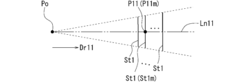
- the second shape information generating unit divides, according to the same rule, T2 (T2 is a natural number of 2 or more) virtual surfaces among the M1 virtual surfaces in each of the T1 surface collections, which include the high-matching virtual surface, intersect with a straight line passing through the reference point and the high-matching virtual camera position on the side of the high-matching virtual camera position relative to the reference point, and have mutually different distances from the reference point, to generate M2 (M2 is a natural number of 2 or more) virtual divided surfaces for each of the T2 virtual surfaces, thereby generating M2 ⁇ T2 virtual
- the substrate processing apparatus is the substrate processing apparatus according to the second aspect, and the search processing unit includes a second detection unit that detects the virtual camera position having the highest degree of match between the actual shape information and the reference shape information from among the high-match virtual camera position and the M2 ⁇ T2 second virtual camera positions.
- the substrate processing apparatus is the substrate processing apparatus according to the third aspect, wherein the search processing unit executes one or more n-th unit processes (n is a natural number equal to or greater than 2) for the target part after executing a first unit process, and the search processing unit sequentially executes a first A process, a first B process, a first C process, and a first D process in the first unit process, and the first A process is a plurality of virtual divided surfaces generated by the division surface generation unit dividing each of the T2 virtual surfaces, and the second detection unit a first virtual division surface including a virtual division surface including a first reference virtual camera position which is a virtual camera position detected first, intersecting a straight line passing through the reference point and the first reference virtual camera position on the side of the first reference virtual camera position relative to the reference point, and having T3 (T3 is a natural number of 2 or more) virtual division surfaces which are different from one another in distance from the reference point, each of which is divided according to the same rule, and the firstB process is a process
- the nB process is a process in which the second shape information generation unit generates the reference shape information for each of the nth M3 ⁇ T3 third virtual camera positions, which are M3 ⁇ T3 virtual camera positions that are set by virtually setting one virtual camera position for each of the nth M3 ⁇ T3 virtual divided surfaces based on the three-dimensional design information, assuming that the three-dimensional model is photographed from each of the nth M3 ⁇ T3 third virtual camera positions.
- the nC process is a process in which the second calculation unit calculates a numerical value indicating the degree of agreement between the actual shape information and the reference shape information for each of the nth M3 ⁇ T3 third virtual camera positions.
- the nD process is a process in which the second detection unit detects the virtual camera position that has the greatest degree of agreement between the actual shape information and the reference shape information among the nth reference virtual camera position and the nth M3 ⁇ T3 third virtual camera positions.
- the substrate processing apparatus is the substrate processing apparatus according to the fourth aspect, and the search processing unit terminates the execution of the nth unit process one or more times in response to the second detection unit detecting a reference virtual camera position from the first reference virtual camera position to the nth reference virtual camera position consecutively a first predetermined number of times as the virtual camera position having the greatest degree of agreement between the actual shape information and the reference shape information.
- the substrate processing apparatus is the substrate processing apparatus according to the fourth aspect, in which the search processing unit terminates the execution of the one or more nth unit processes in response to the nth unit process being executed a second predetermined number of times in the one or more nth unit processes.
- the substrate processing apparatus is the substrate processing apparatus according to any one of the fourth to sixth aspects, and further includes an abnormality detection unit that detects an abnormality in the target part by comparing actual information related to the posture of the target part recognized based on the virtual camera position that has the greatest degree of agreement between the actual shape information and the reference shape information detected by the second detection unit in the last nD process in the one or more nth unit processes, with normal information related to the posture of the target part based on the three-dimensional design information when the state of the target part is normal.
- an abnormality detection unit that detects an abnormality in the target part by comparing actual information related to the posture of the target part recognized based on the virtual camera position that has the greatest degree of agreement between the actual shape information and the reference shape information detected by the second detection unit in the last nD process in the one or more nth unit processes, with normal information related to the posture of the target part based on the three-dimensional design information when the state of the target part is normal.
- the substrate processing apparatus is a substrate processing apparatus according to any one of the second to seventh aspects, and the same rule includes a rule for dividing the surface to be divided into a plurality of surfaces by a plurality of line segments each connecting the center point of the surface to be divided to all of the vertices of the surface to be divided.
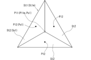
- the substrate processing apparatus is a substrate processing apparatus according to any one of the first to eighth aspects, in which each of the plurality of virtual surfaces is a triangular surface, and the surface assembly is a polyhedron composed of a large number of triangular surfaces.
- the substrate processing apparatus is the substrate processing apparatus according to the ninth aspect, and the division surface generation unit divides the high-match virtual surface into three virtual division surfaces as the plurality of virtual division surfaces by three line segments respectively connecting three vertices of the high-match virtual surface to the high-match virtual camera position.
- An information processing method in a substrate processing apparatus is an information processing method in a substrate processing apparatus for processing substrates, comprising: an actual image acquisition step of acquiring, by a calculation unit, an actual image capturing a target part obtained by photographing by a photographing unit; and a calculation unit generating, by the calculation unit, reference shape information relating to the two-dimensional shape of the three-dimensional model in each of a plurality of virtual images that can be acquired by photographing a three-dimensional model of the target part from a plurality of virtual camera positions, each of which is generated based on three-dimensional design information regarding the target part stored in a memory unit, and actual shape information relating to the two-dimensional shape of the object in the actual image.
- the method includes a division surface generation step of generating a plurality of virtual division surfaces by dividing the surface, a second shape information generation step of generating the reference shape information for each of a plurality of second virtual camera positions, which are a plurality of virtual camera positions that are set by virtually setting one virtual camera position for each of the plurality of virtual division surfaces based on the three-dimensional design information, assuming that the three-dimensional model is photographed from each of the plurality of second virtual camera positions, and a second calculation step of calculating a numerical value indicating the degree of agreement between the actual shape information and the reference shape information for each of the plurality of second virtual camera positions.
- a second virtual camera position is set on each of a plurality of virtual divided surfaces generated by dividing a high-match virtual surface, which is a virtual surface on which a high-match virtual camera position detected by a first detection unit among the plurality of virtual surfaces is set, and a numerical value indicating the degree of match between the actual shape information and the reference shape information is calculated for each second virtual camera position. Therefore, the high-match virtual surface and the plurality of virtual divided surfaces are not unrelated surfaces, and an increase in at least one of the number and area of the plurality of virtual divided surfaces can be reduced. This can reduce the amount of calculation required to recognize the orientation of the target component captured in the actual image. As a result, the orientation of the component can be recognized efficiently in the substrate processing apparatus.
- the substrate processing apparatus can efficiently recognize the orientation of the part when the distance between the image capture unit and the target part changes.
- the substrate processing apparatus can efficiently detect a virtual camera position that provides a greater degree of agreement between the actual shape information and the reference shape information.
- a plurality of virtual division surfaces including a virtual division surface that includes the virtual camera position where the degree of match between the actual shape information and the reference shape information is greatest and that have mutually different distances from the target part, are divided to generate a plurality of virtual division surfaces for which the next virtual camera position is set.
- the virtual division surfaces before division and the virtual division surfaces after division are not unrelated surfaces, and at least one of the increases in the number and area of the virtual division surfaces after division can be reduced. This can reduce the amount of calculation required to recognize the orientation of the target part captured in the actual image. As a result, the orientation of the part can be recognized efficiently in the substrate processing apparatus.
- the substrate processing apparatus can efficiently recognize the orientation of components by reducing the amount of calculation.
- the substrate processing apparatus can efficiently recognize the orientation of components by reducing the amount of calculation.
- the substrate processing apparatus can efficiently recognize actual information related to the posture of the components in the substrate processing apparatus, and therefore can efficiently detect abnormalities in the components.
- the substrate processing apparatus can easily divide the surface.
- the substrate processing apparatus allows for easy setting of a surface group including multiple virtual surfaces.
- the substrate processing apparatus can easily divide the virtual surface.
- a second virtual camera position is set on each of a plurality of virtual divided surfaces generated by dividing the high-match virtual surface, which is a virtual surface on which a high-match virtual camera position detected in the first detection step is set among the plurality of virtual surfaces, and a numerical value indicating the degree of match between the actual shape information and the reference shape information is calculated for each second virtual camera position. Therefore, the high-match virtual surface and the plurality of virtual divided surfaces are not unrelated surfaces, and an increase in at least one of the number and area of the plurality of virtual divided surfaces can be reduced. This can reduce the amount of calculation required to recognize the orientation of the target component captured in the actual image. As a result, the orientation of the component can be recognized efficiently in the substrate processing apparatus.
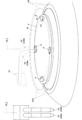
- FIG. 1 is a side view illustrating an example of a schematic configuration of a substrate processing apparatus according to a first embodiment.
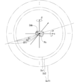
- FIG. 2 is a plan view illustrating an example of a schematic configuration of the substrate processing apparatus according to the first embodiment.
- FIG. 3 is a block diagram showing an example of a functional configuration of the substrate processing apparatus according to the first embodiment.
- FIG. 4 is a block diagram showing a specific example of a functional configuration related to a search process in the control unit.
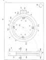
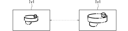
- FIG. 5 is a diagram showing a specific example of an actual image captured by a camera.
- FIG. 6 is a diagram showing a specific example of a processing target region in an actual image.
- FIG. 7 is a diagram showing a specific example of the actual image to be processed.
- FIG. 1 is a side view illustrating an example of a schematic configuration of a substrate processing apparatus according to a first embodiment.
- FIG. 2 is a plan view illustrating an example of a schematic configuration of the substrate processing apparatus according to the first embodiment.
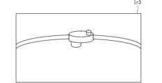
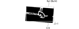
- FIG. 8 is a diagram showing a specific example of an edge image.
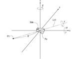
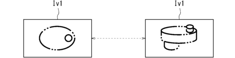
- FIG. 9 is a diagram for explaining the basic concept of the search process.
- FIG. 10 is a diagram for explaining the basic concept of the search process.
- FIG. 11 is a diagram for explaining the basic concept of the search process.
- FIG. 12 is a diagram for explaining the basic concept of the search process.
- FIG. 13 is a diagram for explaining the basic concept of the search process.
- FIG. 14 is a diagram for explaining the basic concept of the search process.
- FIG. 15 is a diagram for explaining the basic concept of the search process.
- FIG. 16 is a diagram for explaining the basic concept of the search process.
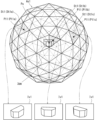
- FIG. 17 is a diagram showing an example of a setting mode of a plurality of first virtual camera positions.
- FIG. 17 is a diagram showing an example of a setting mode of a plurality of first virtual camera positions.
- FIG. 18 is a diagram showing an example of a setting mode of the first virtual camera position on the virtual plane.
- FIG. 19 is a diagram for explaining an example of an aspect in which T1 surface aggregates having mutually different distances from a reference point of a 3D model of a target part are virtually set.
- FIG. 20 is a diagram for explaining a specific example of a process for calculating a numerical value indicating the degree of match between actual shape information and reference shape information for one first virtual camera position.
- FIG. 21 is a diagram for explaining a specific example of a process for calculating a numerical value indicating the degree of match between actual shape information and reference shape information for one first virtual camera position.
- FIG. 20 is a diagram for explaining a specific example of a process for calculating a numerical value indicating the degree of match between actual shape information and reference shape information for one first virtual camera position.
- FIG. 22 is a diagram for explaining a specific example of a process for calculating a numerical value indicating the degree of match between actual shape information and reference shape information for one first virtual camera position.
- FIG. 23 is a diagram for explaining a specific example of a process for calculating a numerical value indicating the degree of match between actual shape information and reference shape information for one first virtual camera position.
- FIG. 24 is a diagram for explaining a specific example of a process for calculating a numerical value indicating the degree of match between actual shape information and reference shape information for one first virtual camera position.
- FIG. 25 is a diagram showing a specific example in which a matching target region is set in an edge image as actual shape information.
- FIG. 26 is a diagram showing a specific example in which a high-match virtual surface is divided into a plurality of virtual divided surfaces.
- FIG. 27 is an image diagram showing an example of T2 virtual surfaces.
- FIG. 28 is a schematic diagram showing an example of the first T3 virtual divided surfaces.
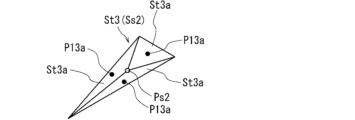
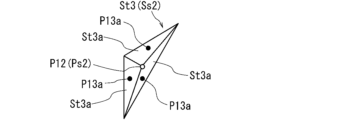
- FIG. 29 is a diagram for explaining a first specific example in which the first M3 ⁇ T3 virtual divided surfaces are generated by the divided surface generating section.
- FIG. 30 is a diagram for explaining a second specific example in which the first M3 ⁇ T3 virtual divided surfaces are generated by the divided surface generating section.
- FIG. 31 is a diagram for explaining a second specific example in which the first M3 ⁇ T3 virtual divided surfaces are generated by the divided surface generating section.
- FIG. 32 is an image diagram showing an example of the second T3 virtual divided surfaces, which is a specific example of the n-th T3 virtual divided surfaces.
- FIG. 33 is a diagram for explaining a first specific example in which the second M3 ⁇ T3 virtual divided surfaces are generated by the divided surface generating section.
- FIG. 34 is a diagram for explaining a second specific example in which the second M3 ⁇ T3 virtual divided surfaces are generated by the divided surface generating section.
- FIG. 35 is a diagram for explaining a second specific example in which the second M3 ⁇ T3 virtual divided surfaces are generated by the divided surface generating section.
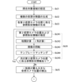
- FIG. 36 is a flow chart showing a specific example of a schematic flow of processing in a substrate processing apparatus.
- FIG. 36 is a flow chart showing a specific example of a schematic flow of processing in a substrate processing apparatus.
- FIG. 37 is a flowchart showing a specific example of the flow of image processing in steps S3 and S10 in FIG.
- FIG. 38 is a flowchart showing a specific example of the process flow in the search process in steps S4 and S11 in FIG.
- FIG. 39 is a flowchart showing a specific example of the process flow in the primary search process in step Sb1 of FIG.
- FIG. 40 is a flowchart showing a specific example of the process flow in the secondary search process in step Sb2 of FIG.
- FIG. 41 is a flowchart showing a specific example of the process flow in the secondary search process in step Sb2 of FIG.
- FIG. 42 is a flowchart showing a specific example of the process flow in the secondary search process in step Sb2 of FIG.
- FIG. 43 is a diagram illustrating an example of a state in which the target part has been moved to the origin position.
- FIG. 44 is a diagram for explaining detection of an abnormality in a chuck.
- FIG. 45 is a diagram for explaining detection of an abnormality in a chuck.
- FIG. 46 is a diagram for explaining detection of abnormalities in the nozzles and guards.
- FIG. 47 is a diagram illustrating an example of a schematic configuration of a substrate processing system.
- a substrate processing apparatus equipped with a processing chamber, a substrate holder, a nozzle, a camera, an image processing unit, and a monitoring unit.
- a substrate holder, a nozzle, and a camera are disposed within a processing chamber.
- the substrate holder rotates the substrate in a horizontal plane while holding the substrate in a horizontal position.
- the nozzle moves between a standby position off to the side of the substrate and a discharge position above the substrate by pivoting a drive arm to which the nozzle is fixed.
- the nozzle is disposed at the standby position when the substrate is attached to or detached from the substrate holder, and is disposed at the discharge position when processing liquid is discharged from the nozzle toward the substrate.
- the camera is disposed at a predetermined position within the processing chamber, and captures an image of a predetermined area including the nozzle that has moved to the discharge position.
- the image processor obtains second nozzle position information indicating the position of the nozzle based on an image from the camera, and outputs the image to a monitoring unit.
- the monitoring unit determines whether or not there is an abnormality in the nozzle position based on the correspondence between the first nozzle position information, which is information directly or indirectly indicating the position of the nozzle from the control unit, and the second nozzle position information from the image processor.
- a nozzle In substrate processing equipment, it may be necessary to recognize the posture of one or more of the various components, such as a nozzle, a chuck that holds the edge of the substrate in the substrate holding part, and a guard that moves up and down in the area surrounding the sides of the substrate holding part, in order to detect abnormalities and operating conditions of the components.
- the various components such as a nozzle, a chuck that holds the edge of the substrate in the substrate holding part, and a guard that moves up and down in the area surrounding the sides of the substrate holding part, in order to detect abnormalities and operating conditions of the components.
- a virtual polyhedron is set that is composed of multiple virtual surfaces along a sphere centered on the three-dimensional design shape of the part (also called the three-dimensional part model), which is represented by the part's three-dimensional CAD (Computer Aided Design) data, etc.
- Each virtual surface is composed of, for example, triangular surfaces.
- a camera also called a virtual camera
- a predetermined position also called a virtual camera position
- multiple virtual cameras are virtually placed so as to surround the 3D part model at the center.
- process B multiple images (also called virtual images) are generated, which are acquired by virtually photographing the three-dimensional part model using multiple virtual cameras installed at multiple virtual camera positions.
- the virtual images can be generated, for example, by projecting the three-dimensional part model onto a virtual plane using a process such as rendering.
- Process D A matching process using template matching or the like is performed between each of the multiple virtual images generated in Process C above and an image (also called a real image) obtained by actually photographing the part with a camera (also called a real camera). This detects the virtual camera position among the multiple virtual camera positions that provides the greatest degree of match (also called the degree of agreement) between the real image and the virtual image in terms of the shape, orientation, size, etc. of the captured part.
- the degree of match (degree of agreement) is also called the degree of similarity (degree of similarity).
- the orientation of the part is recognized based on the detection results in the above process D.
- the detection results in the above process D are used to recognize the orientation of the part based on the position of the actual camera, thereby recognizing the orientation of the part captured in the actual image.
- one possible approach would be to increase the accuracy of recognizing the orientation of the parts by, for example, making the multiple virtual surfaces that make up the virtual polyhedron in process A into a large number of very fine virtual surfaces, and increasing the number of virtual camera positions that are virtually installed in process B.
- this approach would increase the amount of calculation required, which would result in a longer calculation time.
- a method can be considered in which the above processes A to D are repeatedly executed in order a predetermined number of times, and then the above process E is executed.
- a virtual polyhedron in the first execution of the above process A, a virtual polyhedron is constructed from a number of relatively large virtual faces, and in the second and subsequent executions of the above process A, a virtual polyhedron is constructed from a large number of virtual faces that are relatively finer than the previous execution of the above process A, and in the second and subsequent executions of the above process B, virtual cameras are virtually installed at predetermined virtual camera positions on each of a portion of a number of virtual faces of the polyhedron set in the immediately preceding process A that are close to the virtual camera position detected in the most recent process D.
- At least one of the number and area of the part of the multiple virtual surfaces for which the virtual camera position is set in the second and subsequent iterations of the above process B will increase to a certain extent, and the number of virtual camera positions set in the second and subsequent iterations of the above process B may increase, making it difficult to sufficiently reduce the amount of calculations.
- an expression indicating an equal state e.g., "same,” “equal,” “homogeneous,” etc.
- the expression not only strictly indicates a state in which the quantitative relationship is equal, but also indicates a state in which a difference exists within a range in which a tolerance or similar function is obtained, unless otherwise specified.
- an expression indicating a shape e.g., "square shape” or “cylindrical shape,” etc.
- the expression not only strictly indicates the shape geometrically, but also indicates a shape having, for example, any of concaves and convexes and chamfers within a range in which a similar effect is obtained, unless otherwise specified.
- Fig. 1 is a side view showing an example of a schematic configuration of a substrate processing apparatus 1 according to a first embodiment.
- Fig. 2 is a plan view showing an example of a schematic configuration of the substrate processing apparatus 1 according to the first embodiment.
- the substrate processing apparatus 1 is an apparatus for processing a substrate (e.g., a semiconductor wafer) W.
- the substrate processing apparatus 1 is a single-wafer type apparatus for processing substrates W one by one.
- a thin, flat plate having an approximately disk shape is applied to the substrate W.
- the substrate W has a circular shape when viewed from above.
- the plan view refers to a plan view in which each part is viewed from above downward.
- the substrate processing apparatus 1 rotates the substrate W while supplying a processing liquid to perform a predetermined process on the substrate W. For example, a substrate cleaning apparatus that cleans the substrate W using a processing liquid is applied to the substrate processing apparatus 1.
- the substrate processing apparatus 1 is equipped with a housing CA.
- the housing CA isolates the interior of the housing CA from the atmosphere surrounding the housing CA.
- the substrate processing apparatus 1 is equipped with a spin chuck 3.
- the spin chuck 3 has a circular structure with a diameter larger than that of the substrate W in a plan view.
- the upper end of a rotating shaft 5 is connected to the lower surface of the spin chuck 3.
- the lower end of the rotating shaft 5 is connected to a motor 7.
- the spin chuck 3 rotates about a rotation center PL1 by being driven by the motor 7.
- the rotation center PL1 extends in the vertical direction.
- the spin chuck 3 has a plurality of chucks 9. More specifically, the spin chuck 3 has a plurality of chucks 9 on the peripheral portion of the upper surface of the spin chuck 3. In the present first embodiment, the spin chuck 3 has four chucks 9. As long as the spin chuck 3 can stably rotate the substrate W around the rotation center PL1 while supporting the substrate W in a horizontal position, the number of chucks 9 provided on the spin chuck 3 is not limited to four.
- the chuck 9 includes, for example, a lower support portion 11, a peripheral support portion 13, and a rotating magnet 15.
- the lower support portion 11 is a portion for supporting the substrate W by contacting the lower surface of the substrate W from below. For example, if the contact area of the lower support portion 11 with the lower surface of the substrate W is configured to be small, the degree of mutual contamination between the substrate W and the chuck 9 can be reduced.
- the lower support portion 11 is attached to the upper surface side of the main body of the spin chuck 3 so as to be freely rotatable about a rotation center PL2.
- the rotation center PL2 extends in the vertical direction.
- the peripheral support portion 13 is erected on the upper surface of the lower support portion 11.
- the peripheral support portion 13 can stably hold the periphery of the substrate W.
- the peripheral support portion 13 is provided at a position away from the rotation center PL2 toward the outer edge of the lower support portion 11.
- the peripheral support portion 13 is eccentric from the rotation center PL2.
- the rotation magnet 15 is attached to the lower surface side of the spin chuck 3 at a position corresponding to the rotation center PL2.
- the rotation magnet 15 is connected to the lower support portion 11.
- the rotation magnet 15 is provided so as to be freely rotatable around the rotation center PL2.
- the substrate processing apparatus 1 includes a chuck drive mechanism 17 disposed below the rotating magnet 15.
- the chuck drive mechanism 17 is disposed closer to the rotating shaft 5 than the chuck 9.
- the chuck drive mechanism 17 includes, for example, an air cylinder 19 and a drive magnet 21.
- the drive magnet 21 has an annular shape when viewed from above.
- the air cylinder 19 has a piston rod (also called a rod or an actuating shaft) positioned along the vertical direction.
- the drive magnet 21 is attached to the upper end of the rod of the air cylinder 19.
- the chuck drive mechanism 17 is operated in response to a chuck operation command from the control unit 45.
- the chuck drive mechanism 17 can move the drive magnet 21 closer to the chuck 9 by raising the drive magnet 21 with the air cylinder 19, and can move the drive magnet 21 away from the chuck 9 by lowering the drive magnet 21 with the air cylinder 19.
- the chuck drive mechanism 17 can move the drive magnet 21 between an elevated position (also called the elevated position) and a lowered position (also called the lowered position).
- the chuck 9 is equipped with a biasing mechanism (not shown).
- a biasing mechanism (not shown).
- the driving magnet 21 descends and moves from the raised position to the lowered position, the chuck 9 moves from the open position to the closed position.
- the driving magnet 21 ascends and moves from the lowered position to the raised position, the chuck 9 moves from the closed position to the open position.
- the peripheral support portion 13 rotates around the rotation center PL2, and the peripheral support portion 13 moves in a direction approaching the rotation center PL1 and abuts against the periphery of the substrate W. This allows the multiple chucks 9 to clamp the substrate W in the closed position.
- the peripheral support portion 13 rotates around the rotation center PL2, and the peripheral support portion 13 moves in a direction away from the rotation center PL1. This causes the multiple chucks 9 to not clamp the substrate W in the open position. In this state, the substrate W can be loaded onto the spin chuck 3 from outside the housing CA, and can be unloaded from the spin chuck 3 to outside the housing CA.
- the position of the chuck 9 is a position (also called the origin position or chuck origin position) where the peripheral support part 13 has moved slightly inward of the substrate W from the position of the outer edge of the substrate W that is assumed when the substrate W is placed on the lower support part 11.
- the position of the peripheral support part 13 is located closer to the rotation center PL1 than the position when the chuck 9 is in the closed position.
- the substrate processing apparatus 1 is equipped with an origin sensor Z1 arranged near the rotating magnet 15 of the chuck 9.
- the origin sensor Z1 changes the signal (also called the output signal) output from the origin sensor Z1.
- the origin sensor Z1 turns on the output signal.
- the substrate processing apparatus 1 is equipped with a guard 23 arranged around the spin chuck 3.
- the guard 23 surrounds the sides of the spin chuck 3.
- the guard 23 is a part for preventing the processing liquid from scattering from the substrate W supported and rotated by the spin chuck 3 to the surroundings.
- the guard 23 has a cylindrical shape.
- the guard 23 has an opening 23a formed at the top. The inner diameter of the opening 23a is larger than the outer diameter of the spin chuck 3.
- the substrate processing apparatus 1 is provided with a guard moving mechanism 25 capable of raising and lowering the guard 23.
- the guard moving mechanism 25 comprises, for example, an air cylinder 27 and a locking piece 29.
- the guard moving mechanism 25 is arranged, for example, on the outer periphery of the guard 23.
- the guard moving mechanism 25 may be arranged on the inner periphery of the guard 23 as long as it is capable of raising and lowering the guard 23.
- the air cylinder 27 has a piston rod (also called a rod or an actuating shaft) positioned along the vertical direction.
- a locking piece 29 is attached to the upper end of the rod of the air cylinder 27.
- the locking piece 29 is fixed to the outer periphery of the guard 23.
- the guard moving mechanism 25 is not limited to the above configuration as long as it is capable of raising and lowering the guard 23.
- the guard moving mechanism 25 moves the guard 23 between the origin position and the processing position in response to a guard operation command from the control unit 45.
- the origin position of the guard 23 is the position of the guard 23 when the guard 23 is lowered by the guard moving mechanism 25. In other words, the origin position is the position where the upper end of the guard 23 is low.
- the processing position of the guard 23 is the position of the guard 23 when the guard 23 is raised by the guard moving mechanism 25. In other words, the origin position is a position lower than the processing position, and the processing position is a position higher than the origin position.
- the position of the upper edge of the guard 23 is lower than the position of the substrate W supported by the spin chuck 3.
- the substrate processing apparatus 1 is equipped with, for example, an origin sensor Z2 disposed on the inner peripheral side of the guard 23.
- the origin sensor Z2 changes the signal (output signal) output from the origin sensor Z2. For example, when the guard 23 moves to the origin position, the origin sensor Z2 turns on the output signal.
- the substrate processing apparatus 1 is provided with a drainage port (not shown) located on the inner periphery of the guard 23.
- the drainage port is a portion for recovering processing liquid that has scattered around from the substrate W supported and rotated by the spin chuck 3 and received on the inner periphery of the guard 23.
- the number of guards 23 is not limited to one, and may be multiple.
- the number of drainage ports is not limited to one, and may be multiple. If there are multiple guards 23, a drainage port may be provided for each guard 23.
- multiple guards 23 and multiple drainage ports may be configured so that each guard 23 is raised and lowered by a guard moving mechanism 25 to switch the combination of the guard 23 that receives processing liquid scattered from the substrate W and the drainage port that recovers the processing liquid received on the inner periphery of the guard 23.
- each guard 23 can be raised and lowered by the guard movement mechanism 25, allowing a combination of a guard 23 that receives processing liquid splashed from the substrate W and a waste liquid port that collects the processing liquid received on the inner surface of the guard 23 to be switched.
- the substrate processing apparatus 1 includes a processing liquid supply mechanism 31.
- the processing liquid supply mechanism 31 may be disposed on the outer periphery of the guard 23.
- the processing liquid supply mechanism 31 includes, for example, a nozzle 33, a base portion 37, and a nozzle movement mechanism 35.
- the processing liquid supply mechanism 31 includes, for example, two nozzles 33.
- the nozzle 33 on the left side in FIG. 2 will be appropriately referred to as nozzle 33A, and the nozzle 33 on the right side as nozzle 33B.
- the number of nozzles 33 in the processing liquid supply mechanism 31 may be one, or three or more.
- the two nozzles 33 have the same configuration.
- Nozzle 33 includes, for example, extension portion 33a, hanging portion 33b, and tip portion 33c.
- One end of extension portion 33a of nozzle 33 is attached to base portion 37.
- Extension portion 33a extends horizontally from base portion 37.
- the other end of extension portion 33a is connected to hanging portion 33b.
- Hanging portion 33b extends vertically downward from extension portion 33a.
- Tip portion 33c is located on the lower end side of hanging portion 33b.
- Tip portion 33c ejects processing liquid from the lower surface side. Examples of processing liquid include photoresist liquid, SOG (Spin-on-Glass) liquid, developer, rinse liquid, pure water, and cleaning liquid.
- the nozzle moving mechanism 35 includes, for example, a motor 39, a rotating shaft 41, and a position detection unit 43.
- the motor 39 is disposed in a vertical position.
- the rotating shaft 41 is rotated around the rotation center PL3 by the motor 39.
- the rotating shaft 41 is connected to the base unit 37.
- the base unit 37 is rotated by the drive of the motor 39.
- the nozzle 33 is oscillated around the rotation center PL3 together with the base unit 37 by the nozzle moving mechanism 35.
- the position detection unit 43 detects the position (also called the rotation position) of the rotating shaft 41 in the rotation direction around the rotation center PL3 of the rotating shaft 41.
- the position detection unit 43 detects the angle of the rotating shaft 41 around the rotation center PL3 in a plan view.
- the position detection unit 43 outputs a pulse signal according to, for example, the rotation position of the rotating shaft 41.
- the substrate processing apparatus 1 is provided with a standby cup 44 arranged at a position away from the guard 23 to the side in a plan view.
- the standby cup 44 is arranged so that the tip 33c of the nozzle 33 can be located above the standby cup 44 in a plan view. From another perspective, the standby cup 44 is located below the origin position of the nozzle 33.
- the standby cup 44 is a part for preventing the tip 33c of the nozzle 33 from drying.
- the standby cup 44 is used for idle discharge of the processing liquid from the nozzle 33.
- the nozzle moving mechanism 35 drives the motor 39 to oscillate the nozzle 33.
- the nozzle moving mechanism 35 moves the tip 33c of the nozzle 33 between the origin position and a discharge position above the rotation center PL1 of the spin chuck 3 in response to a nozzle operation command from the control unit 45.
- the discharge position of the nozzle 33 is the position where the nozzle 33 is located when the processing liquid is discharged from the tip 33c of the nozzle 33 onto the substrate W.
- the substrate processing apparatus 1 is provided with, for example, an origin sensor Z3 arranged on the outer periphery side of the rotating shaft 41.
- the origin sensor Z3 changes a signal (output signal) output from the origin sensor Z3.
- the origin sensor Z3 turns on the output signal.
- the origin sensor Z3 may be omitted to simplify the configuration.
- a protrusion also called a rotation side protrusion
- a protrusion also called a fixed side protrusion
- the position detection unit 43 may detect that the nozzle 33 is located at the origin position by detecting that the rotation side protrusion of the rotating shaft 41 abuts against the fixed side protrusion due to the rotation of the rotating shaft 41 around the rotation center PL3 of the rotating shaft 41, making it impossible to rotate the rotating shaft 41 around the rotation center PL3 of the rotating shaft 41.
- the position of the nozzle 33 at the point when the pulse signal of the position detection unit 43 becomes unchanged may be treated as the origin position.
- the substrate processing apparatus 1 is equipped with a camera CM as an imaging section.
- the camera CM captures an image (also called an actual image) of one or more target parts described later by imaging.
- the camera CM is attached, for example, to a part of the housing CA.
- the camera CM may be positioned anywhere as long as the target parts described later fit within its field of view.
- the camera CM has, for example, a viewing angle (angle of view) where all of the one or more target parts described later fit within its field of view.
- the camera CM has, for example, a viewing angle (angle of view) where all of the origin positions of the one or more target parts described later fit within its field of view.
- the substrate processing apparatus 1 includes a control unit 45, an instruction unit 47, and an alarm unit 49.
- the control unit 45 will be described in detail later.
- the instruction unit 47 is operated by an operator of the substrate processing apparatus 1.
- the instruction unit 47 is, for example, a keyboard or a touch panel.
- the instruction unit 47 outputs a signal to the control unit 45 in response to the operation of the operator.
- the instruction unit 47 instructs the target part, the timing to check, the tolerance range, the recipe, the start of processing, and the like, which will be described later.
- the alarm unit 49 When the control unit 45 detects an abnormality, the alarm unit 49 notifies the operator of the abnormality. Examples of the alarm unit 49 include a display, a lamp, and a speaker.
- the alarm unit 49 operates in response to a signal from the control unit 45, for example.
- FIG. 3 is a block diagram showing an example of a functional configuration of the substrate processing apparatus 1 according to the first embodiment.
- the control unit 45 includes, for example, a calculation unit 45a and a memory unit 45b.
- the calculation unit 45a has, for example, an electronic circuit that functions as a processor such as a central processing unit (CPU), and an electronic circuit that functions as a memory such as a random access memory (RAM) that temporarily stores data for the processor to execute processing.
- the memory unit 45b has, for example, a portion that functions as a non-volatile storage medium such as a hard disk or flash memory.
- the memory unit 45b may have, for example, a portion that functions as one non-volatile storage medium, or may have portions that function as two or more non-volatile storage media.
- the calculation unit 45a has a plurality of functional components, including an operation control unit 51, an image processing unit 59, a search processing unit 61, and an abnormality detection unit 63.
- the storage unit 45b stores, for example, recipe information 53, parameter information 55, design information 57, and a program Pg1.
- the operation control unit 51, the image processing unit 59, the search processing unit 61, and the abnormality detection unit 63 may be functional processing units (also called functional processing units) that are realized by the CPU reading and executing the program Pg1 in the storage unit 45b.
- the operation control unit 51 controls the operation of the motors 7, 39, air cylinders 19, 27, and camera CM described above. Signals are provided to the operation control unit 51 from the origin sensors Z1, Z2, and Z3, and the position detection unit 43.
- the operation control unit 51 controls the operation of each part, such as the motors 7, 39, air cylinders 19, 27, and camera CM, according to, for example, a recipe in the recipe information 53 stored in the memory unit 45b. For example, after an operator instructs each part to start operating based on the recipe, the operation control unit 51 outputs various operation commands to each part based on the recipe, causing each part, such as the motor 7, to operate at a predetermined timing.
- the recipe information 53 is information indicating various recipes pre-stored in the memory unit 45b.
- the recipes prescribe various procedures for processing the substrate W.
- the operator can instruct the execution of a desired recipe by operating the instruction unit 47.
- the parameter information 55 is information such as the confirmation timing and tolerance range for each target part, which is stored in advance in the storage unit 45b.
- the target parts are parts that are the target of a specific process among the parts that make up the substrate processing apparatus 1. In the first embodiment, the specific process includes detection of an abnormality.
- the confirmation timing is the timing for checking the operating state of the target parts.
- the confirmation timing may overlap with the timing when the operation control unit 51 outputs an operation command, or may overlap with the timing when the target parts complete their movement in response to this operation command.
- the target parts, the confirmation timing, the tolerance range, etc. can be arbitrarily set by the operator operating the instruction unit 47. The operator can instruct from the instruction unit 47 which parts are to be the target parts, which timing is to be the confirmation timing, and the range (tolerance range) in which the error in the position of the target parts is to be tolerated.
- the target parts may include, for example, the chuck 9, the guard 23, and the nozzle 33.
- the timings requiring confirmation may include, for example, the timing when the chuck drive mechanism 17 moves the chuck 9 in response to a chuck operation command and the movement of the chuck 9 is completed, the timing when the nozzle movement mechanism 35 moves the nozzle 33 in response to a nozzle operation command and the movement of the nozzle 33 is completed, the timing when the guard movement mechanism 25 raises and lowers the guard 23 in response to a guard operation command and the movement of the guard 23 is completed, the timing when the chuck 9 is set to be in the closed position by the chuck operation command, the timing when the nozzle 33 is set to be in the discharge position by the nozzle operation command, and the timing when the guard 23 is set to be in the processing position by the guard operation command.
- the tolerance range indicates the degree of tolerance for the position that the target part should be in if the target part were operating normally at the time to be checked.
- the tolerance range is, for example, the degree to which the target part is tolerant of deviation from the position and angle intended by the design.
- the tolerance range indicates the range of deviation of the target part that is acceptable for processing the board W, based on the processing of the board W, even if the target part deviates from the position and angle intended by the design at the time to be checked.
- the above-mentioned operation control unit 51 based on the pulse signal from the position detection unit 43 and the parameter information 55 in the memory unit 45b, notifies the search processing unit 61 of information indicating the nozzle 33 as a target part at the confirmation timing and information indicating the position (e.g., the discharge position) where the nozzle 33 as a target part at the confirmation timing should be at the confirmation timing, if the nozzle 33 is at the confirmation timing as a target part, based on the pulse signal from the position detection unit 43 and the parameter information 55 in the memory unit 45b. If the target part is located at the origin position, based on the signals from the origin sensors Z1, Z2, and Z3, the operation control unit 51 notifies the search processing unit 61 of information identifying the target part located at the origin position.
- the operation control unit 51 does not need to notify the search processing unit 61 of information identifying the target part located at the origin position.
- the operation control unit 51 In response to controlling the operation of the air cylinders 19, 27 and the motor 39, the operation control unit 51 notifies the search processing unit 61 of information about the target part that is in the confirmation timing and information indicating the position where the target part should be at the confirmation timing (for example, the closed position of the chuck 9, the discharge position of the nozzle 33, or the processing position of the guard 23, etc.) for each target part, if the target part is in the confirmation timing.
- the operation control unit 51 does not need to notify the search processing unit 61 of information about the target part that is in the confirmation timing.
- the operation control unit 51 may notify the search processing unit 61 that it has output an operation command to each unit according to the recipe.
- Design information 57 includes design information stored in memory unit 45b relating to the components constituting substrate processing apparatus 1. Design information 57 may also include design information relating to substrates W as the processing target in substrate processing apparatus 1. Design information 57 includes, for example, 3D-CAD (three-dimensional Computer Aided Design) data. Design information 57 may also include physical property information relating to the processing liquid and various materials used in processing.
- design information 57 includes design information stored in memory unit 45b relating to the components constituting substrate processing apparatus 1.
- Design information 57 may also include design information relating to substrates W as the processing target in substrate processing apparatus 1.
- Design information 57 includes, for example, 3D-CAD (three-dimensional Computer Aided Design) data. Design information 57 may also include physical property information relating to the processing liquid and various materials used in processing.
- the 3D-CAD data is expressed, for example, by three orthogonal coordinate axes, and is expressed by information on the position and angle of the parts (also collectively referred to as position information) when the parts are arranged in a three-dimensional space.
- the storage unit 45b pre-stores design information related to at least the target parts transferred from a host computer (not shown). In other words, the storage unit 45b stores three-dimensional design information related to the target parts.
- the host computer may store 3D-CAD data related to all parts and materials of the substrate processing apparatus 1 as three-dimensional design information.
- the design information 57 stored in the storage unit 45b is limited to the design information of the target parts, rather than design information related to all parts of the substrate processing apparatus 1, the storage capacity of the storage unit 45b can be saved.
- the image processing unit 59 processes the actual image obtained by shooting with the camera CM.
- the image processing unit 59 performs image processing on the actual image to extract information relating to the two-dimensional shape of the object captured in the actual image (also referred to as actual shape information).
- the image processing unit 59 extracts actual shape information, for example, by performing a process to extract contours for all parts captured in all areas of the actual image or in a predetermined partial area.
- the contour here may include not only the contour of the outer shape of the part, but also the edge portion located inside the outer shape of the part.
- the actual shape information extracted by the image processing unit 59 is provided to the search processing unit 61.
- the search processing unit 61 performs a process (also called a search process) of searching for a virtual camera position (also called a virtual camera position) that has the highest degree of agreement between the reference shape information and the actual shape information among a plurality of virtual camera positions (also called a virtual camera position) based on a plurality of reference shape information and actual shape information.
- the plurality of reference shape information is information generated based on three-dimensional design information on the target part stored in the storage unit 45b.
- the plurality of reference shape information is information related to the two-dimensional shape of the 3D model of the target part in each of a plurality of virtual images (also called virtual images) that can be obtained by photographing a three-dimensional model (also called a 3D model) of the target part from a plurality of virtual camera positions.
- one piece of reference shape information is information generated based on three-dimensional design information on one target part, and is information related to the two-dimensional shape of the 3D model of the target part in a virtual image that can be obtained by photographing the 3D model of the target part from one virtual camera position.
- the 3D model of the target part is a three-dimensional model of the target part that is virtually generated based on three-dimensional design information on the target part.
- the virtual image may be generated, for example, by projecting a 3D model onto a virtual plane by a process such as rendering.
- the degree of agreement between the reference shape information and the actual shape information refers, for example, to the degree to which the reference shape information is similar to the actual shape information. The greater the degree of agreement, the closer the reference shape information is to the actual shape information, and the smaller the degree of agreement, the more the reference shape information differs from the actual shape information.
- the degree of agreement between the reference shape information and the actual shape information is represented, for example, by a numerical value indicating the degree of agreement between the reference shape information and the actual shape information. The degree of agreement and the numerical value indicating the degree of agreement will be described further below.
- the information relating to the two-dimensional shape of the 3D model may be, for example, a figure.
- the search process of the search processing unit 61 can search for a target part captured in an actual image captured by the camera CM that has the greatest degree of match with the two-dimensional shape of a 3D model of the target part in a virtual image that can be captured by shooting from which of a plurality of virtual camera positions. Based on the results of this search, the search processing unit 61 can recognize the orientation of the target part.
- the search processing unit 61 performs a search process on at least the target part for which confirmation is required. This allows the posture of the target part for which confirmation is required to be recognized in the substrate processing apparatus 1.
- the search processing unit 61 outputs information (also called reality information) relating to the posture of the target part recognized using the actual image to the abnormality detection unit 63.
- the reality information is, for example, information relating to the posture of the target part based on the virtual camera position with the greatest degree of match detected by the search processing unit 61.
- This reality information is based on the actual image, and is information representing the state in which the target part is actually positioned in the substrate processing apparatus 1 at the confirmation time.
- the search processing unit 61 may perform search processing for target parts even when the timing is not a timing requiring confirmation, in response to instructions from the operation control unit 51 based on output signals from the origin sensors Z1, Z2, and Z3. For example, in response to instructions from the operation control unit 51 based on output signals from the origin sensors Z1, Z2, and Z3, the search processing unit 61 may perform search processing (also called origin search processing) for target parts located at the origin position.
- search processing also called origin search processing
- the origin search processing may be performed only once for each target part, for example, when the substrate processing apparatus 1 is started and processing of the substrate W is started.
- the search processing unit 61 may perform search processing for target parts at any timing, including a timing requiring confirmation.
- the abnormality detection unit 63 detects an abnormality in the target part according to the information output from the search processing unit 61. Specifically, the abnormality detection unit 63 detects an abnormality in the target part by comparing information on the posture of the target part based on the virtual camera position at which the degree of agreement between the actual shape information and the reference shape information detected by the search processing unit 61 is the greatest (real information) with information on the posture of the target part based on three-dimensional design information when the state of the target part is normal (also called normal information). More specifically, the abnormality detection unit 63 detects an abnormality in the target part when the real information and normal information do not match as a result of comparing the real information and normal information about the target part.
- the normal information about the target part may include information on the posture of the target part when it is within an acceptable range.
- matching the real information with the normal information includes matching information on the posture of any target part within the acceptable range of the normal information with information on the posture of the target part in the real information.
- the abnormality detection unit 63 causes the notification unit 49 to perform a notification operation according to the detection result. Specifically, the abnormality detection unit 63 causes the notification unit 49 to perform a notification operation in response to the detection of an abnormality in the target part.
- the notification operation may be, for example, an operation to notify the occurrence of an abnormality.
- the notification unit 49 may also notify, for example, information identifying the target part in which the abnormality was detected together with the occurrence of the abnormality, or may also notify the position information of the target part in which the abnormality was detected.
- examples of the information identifying the target part in which the abnormality was detected include, for example, a character string or a voice indicating a name or symbol identifying each of the multiple chucks 9, a name or symbol identifying each of one or more guards 23, and a name or symbol identifying each of one or more nozzles 33.
- Examples of information indicating the position information of the target part in which the abnormality was detected include various information such as a character string or a voice indicating the closed position and open position of the chuck 9, the origin position and processing position of the guard 23, and the origin position and discharge position of the nozzle 33.
- FIG. 4 is a block diagram showing a specific example of a functional configuration related to the search process in the control unit 45.
- Fig. 4 shows the functional configurations of the storage unit 45b, the image processing unit 59, and the search processing unit 61 among the multiple functional configurations in the control unit 45.
- the image processing unit 59 has, as a plurality of functional processing units, for example, a processing target area extraction unit 591 and a contour extraction unit 592.
- the processing target area extraction unit 591 and the contour extraction unit 592 are realized, for example, in the control unit 45 (more specifically, the calculation unit 45a) by the CPU reading and executing the program Pg1 stored in the storage unit 45b.
- the processing target area extraction unit 591 acquires an actual image of the target part captured by the camera CM, and extracts from this actual image a portion related to the area to be processed (also referred to as the processing target area) as an image (also referred to as the processing target actual image). This can reduce the amount of computational processing, for example, in the processing in the contour extraction unit 592 and the processing in the search processing unit 61. As a result, the orientation of the target part can be recognized efficiently.
- FIGS. 5 to 7 are diagrams for explaining the process of extracting a portion related to the processing target area from a real image.
- FIG. 5 shows a specific example of a real image Ir1 obtained by shooting with a camera CM.
- FIG. 6 shows a specific example of a processing target area R1 in the real image Ir1.
- FIG. 7 shows a specific example of a processing target real image Ir2 extracted from the real image Ir1.
- the processing target area extraction unit 591 acquires the actual image Ir1 shown in FIG. 5, for example, it extracts the portion of the actual image Ir1 that is related to the processing target area R1 surrounded by a thick two-dot chain line as shown in FIG. 6, thereby obtaining the processing target actual image Ir2 as shown in FIG. 7.
- the processing target area R1 may be set in advance for each target part so as to include an area on the actual image where the target part may be present at the confirmation timing.
- the processing target area R1 may be set by referring to an actual image captured in advance by the camera CM, or may be set based on the design information of the parts that make up the substrate processing apparatus 1 and the shooting direction and angle of view of the camera CM.
- the contour extraction unit 592 extracts information relating to the two-dimensional shape of the object captured in the actual image (actual shape information) by, for example, performing a process of extracting contours for all parts captured in the actual image Ir2 to be processed obtained by the processing target area extraction unit 591. This allows the image processing unit 59 to obtain actual shape information relating to the two-dimensional shape of the object captured in the actual image.
- the actual shape information obtained by the image processing unit 59 is provided to the search processing unit 61.
- the processing target real image Ir2 obtained by the processing target area extraction unit 591 may be regarded as a real image capturing the target part.
- the contour may include not only the contour of the outer shape of the part, but also the edge portion located inside the outer shape of the part.
- the process of extracting the contour may be realized using, for example, a method of detecting edges such as the Canny method.
- the detected edges may be subjected to a process of expanding lines such as morphological transformation, thereby extracting contours for all parts captured in the processing target real image Ir2.
- the actual shape information may be, for example, an edge image showing the contour of an object captured in the actual image.
- the edge image for example, a binary image that can distinguish the contour of the object from other parts is adopted.
- the edge image as the actual shape information can be said to be information showing the two-dimensional shape of the object in the actual image.
- the actual shape information may be, for example, information showing the two-dimensional shape of the object in the actual image.
- FIG. 8 is a diagram showing a specific example of the edge image Ir3 as the actual shape information acquired by the contour extraction unit 592.
- the edge image Ir3 illustrated in FIG. 8 is an example of an edge image obtained by performing a process to extract the contours of all parts captured in the actual processing target image Ir2 illustrated in FIG. 7.
- the edge image Ir3 illustrated in FIG. 8 is a binary image in which the contours of the parts extracted by the contour extraction unit 592 are shown in white and the other parts are shown in black.
- An example of the basic concept of search processing> 9 to 16 are diagrams for explaining an example of the basic concept of the search process.
- a 3D model 3dm of a target part which is a three-dimensional model of a target part virtually generated based on three-dimensional design information related to the target part (e.g., a chuck 9), is set as the center, and while a plurality of virtual camera positions (virtual camera positions) P1 are appropriately set, information (reference shape information) related to the two-dimensional shape of the 3D model 3dm of the target part in a virtual image (virtual image) that can be acquired by photographing the 3D model 3dm of the target part from each virtual camera position P1 is generated. That is, reference shape information is generated for each virtual camera position P1.
- this reference shape information for example, as shown in FIG.
- an image (also called a reference image) Iv1 showing the outline as the two-dimensional shape of the 3D model 3dm of the target part in a virtual image that can be acquired by photographing the 3D model 3dm of the target part from each virtual camera position P1 can be adopted.
- the reference image as the reference shape information is information showing the two-dimensional shape of the 3D model 3dm in the virtual image.
- the reference shape information may be, for example, information indicating the two-dimensional shape of the 3D model 3dm in the virtual image.
- FIG. 10 shows an example of a reference image Iv1 in which the contour of the 3D model 3dm of the target part is drawn with a thick two-dot chain line for convenience.
- the reference image Iv1 illustrated in FIG. 10 is a binary image in which the contour of the two-dimensional shape of the 3D model 3dm of the target part is shown in black, and the other parts are shown in white.
- a numerical value indicating the degree of matching is calculated between each of the multiple reference images Iv1 as multiple reference shape information obtained for the multiple virtual camera positions P1 and the edge image Ir3 as actual shape information related to the two-dimensional shape of the object captured in the actual image as shown in FIG. 11.
- the edge image Ir3 illustrated in FIG. 11 is a binary image in which the contour of the object is shown in black and the other parts are shown in white.
- the reference image Iv1 as the reference shape information is rotated and translated relative to the edge image Ir3 as the actual shape information.
- a numerical value indicating the degree of matching when the degree of matching of the reference image Iv1 as the reference shape information with the edge image Ir3 as the actual shape information is maximized can be calculated as a numerical value indicating the degree of matching between the edge image Ir3 as the actual shape information and the reference image Iv1 as the reference shape information.
- a numerical value indicating the degree of matching between the edge image Ir3 as actual shape information and the reference image Iv1 as reference shape information when the degree of matching is maximum for the edge image Ir3 as actual shape information can be calculated as a numerical value indicating the degree of matching between the edge image Ir3 as actual shape information and the reference image Iv1 as reference shape information.
- a numerical value indicating the degree of matching between the edge image Ir3 as actual shape information and the reference image Iv1 as reference shape information when the degree of matching is maximum for the edge image Ir3 as actual shape information is regarded as the degree of matching between the edge image Ir3 as actual shape information and the reference image Iv1 as reference shape information.
- the virtual camera position P1 that provides the greatest degree of match between the edge image Ir3 as actual shape information and the reference image Iv1 as reference shape information is detected. This makes it possible to search for the target part that has the greatest degree of match with the two-dimensional shape of the 3D model 3dm of the target part in the virtual image that can be obtained by shooting from which virtual camera position out of the multiple virtual camera positions.
- a right-handed xyz coordinate system is set with the center of the 3D model 3dm of the target part as the origin, which is the reference point Po.
- the center of gravity of the 3D model 3dm is applied to the center of the 3D model 3dm.
- multiple virtual camera positions P1 centered on the 3D model 3dm can be defined by an angle (also called latitude) ⁇ in the direction of rotation about the x axis, an angle (also called longitude) ⁇ in the direction of rotation about the z axis, and a distance D from the origin.
- attitude of the virtual camera that captures the 3D model 3dm of the target part from the virtual camera position P1 can be defined by an angle (also called roll angle) ⁇ in the direction of rotation about a straight line Ln1 drawn by a thin dashed line that passes through the reference point Po and the virtual camera position P1.
- the latitude ⁇ and longitude ⁇ that define the virtual camera position P1 change, the direction in which the 3D model 3dm of the target part is photographed from the virtual camera position P1 changes. For this reason, when the latitude ⁇ and longitude ⁇ that define the virtual camera position P1 change, the two-dimensional shape of the contour of the 3D model 3dm of the target part, which is drawn with a thick two-dot chain line in the reference image Iv1 as the reference shape information, may change in shape, for example, as shown in FIG. 14.
- the distance D that defines the virtual camera position P1 changes, the direction in which the 3D model 3dm of the target part is photographed from the virtual camera position P1 does not change. For this reason, if the distance D that defines the virtual camera position P1 changes, for example, as shown in FIG. 15, the two-dimensional shape of the contour of the 3D model 3dm of the target part, which is drawn with a thick two-dot chain line in the reference image Iv1 as the reference shape information, may change in size without changing in shape.
- the roll angle ⁇ that defines the attitude of the virtual camera at the virtual camera position P1 changes, for example, as shown in FIG. 16, the orientation of the two-dimensional shape of the contour of the 3D model 3dm of the target part, which is drawn by a thick two-dot chain line in the reference image Iv1 as the reference shape information, can change without changing the shape or size.
- the search processing unit 61 performs a primary search process, and then performs a secondary search process using the results of the primary search process.
- the search process includes a primary search process and a secondary search process that are performed in sequence.
- the primary search process is a process in which the latitude ⁇ and longitude ⁇ are roughly different to a certain extent to calculate a numerical value indicating the degree of agreement between the reference shape information and the actual shape information for a limited number of virtual camera positions P1, and detects the virtual camera position P1 at which the degree of agreement between the reference shape information and the actual shape information is the greatest.
- the secondary search process is a process in which, based on the virtual camera position P1 detected in the primary search process, a virtual camera position P1 at which the degree of agreement between the reference shape information and the actual shape information is greater is searched for in more detail.
- a roll angle ⁇ at which the degree of agreement is greater is also calculated, and the numerical value indicating the degree of agreement is calculated taking this roll angle ⁇ into consideration.
- the latitude ⁇ , longitude ⁇ , distance D, and roll angle ⁇ for the virtual camera position P1 at which the degree of match between the reference shape information and the actual shape information is the greatest can be obtained as a result of the search process.
- the orientation of the 3D model 3dm based on the virtual camera position P1 at which the degree of match between the reference shape information and the actual shape information is the greatest can be recognized using these latitude ⁇ , longitude ⁇ , distance D, and roll angle ⁇ . Therefore, according to the result of the search process, the orientation of the target part based on the position of the camera CM that captured the actual image capturing the target part can be recognized.
- the orientation of the target part captured in the actual image can be recognized.
- the orientation of the target part may be recognized in the form of latitude ⁇ , longitude ⁇ , distance D, and roll angle ⁇ .
- the search processing unit 61 has, as a plurality of function processing units, for example, a first search processing unit 611 and a second search processing unit 612.
- the first search processing unit 611 and the second search processing unit 612 are realized, for example, by the CPU in the control unit 45 (more specifically, the calculation unit 45a) reading and executing the program Pg1 stored in the storage unit 45b.
- the first search processing unit 611 is a part that performs processing related to the primary search processing
- the second search processing unit 612 performs processing related to the secondary search processing.
- the first search processing unit 611 includes, as a plurality of functional processing units, for example, a density determination unit 6111, a first shape information acquisition unit 6112, a first calculation unit 6113, and a first detection unit 6114.
- the density determination unit 6111, the first shape information acquisition unit 6112, the first calculation unit 6113, and the first detection unit 6114 are realized, for example, by a CPU in the control unit 45 (more specifically, the calculation unit 45a) reading and executing a program Pg1 stored in the storage unit 45b.
- the first shape information acquisition unit 6112, the first calculation unit 6113, and the first detection unit 6114 can realize the primary search process.
- the density determination unit 6111 determines, for example, an area where the density of the contours of the components is low (also called a low-density area) from an edge image serving as actual shape information acquired by the contour extraction unit 592.
- the ratio of the contour of the component to each region of a predetermined size (also called a unit determination region) is calculated as the density of the contour of the component.
- a unit determination region having a density equal to or lower than a predetermined value may be determined as a low density region.
- the predetermined size of the unit determination region may be determined according to the size of the reference image as the above-mentioned reference shape information, for example.
- the predetermined value may be set to a numerical value, such as zero, for example.
- a unit determination area in the edge image as actual shape information that does not include any contours of the part is determined to be a low-density area.
- the determination result in the density determination unit 6111 is provided to the first calculation unit 6113 and the second search processing unit 612.
- the low-density area does not include the contours of the target part.
- the low-density area in the edge image as actual shape information is excluded from the calculation for calculating a numerical value indicating the degree of match between the actual shape information and the reference shape information, thereby reducing the amount of calculation required for the search process.
- the first shape information acquisition unit 6112 acquires images of the target part from each of a plurality of virtual camera positions (also referred to as first virtual camera positions) based on, for example, three-dimensional design information related to the target part stored in the storage unit 45b.
- the reference shape information is acquired for each of the first virtual camera positions assuming a case where the 3D model is photographed.
- the first virtual camera positions are located at a reference point of the 3D model of the target part.
- a surface group also called a surface group
- the reference shape information is generated based on three-dimensional design information of the target part.
- the information is related to the two-dimensional shape of the 3D model of the target part in a virtual image that can be acquired by shooting from a virtual camera position. It may be set to a central point such as the center of gravity of the 3D model.
- the number of the multiple virtual surfaces constituting the surface collection is set to M1 (M1 is a natural number equal to or greater than 2), so that the multiple first virtual camera positions are M1 first virtual camera positions
- a first virtual camera position is virtually set at a predetermined position on the virtual surface.
- the position of the center of the virtual surface is applied to the predetermined position.
- the center of the virtual surface is, for example, the center of gravity of the virtual surface.
- a triangular surface is applied to each of the multiple virtual surfaces that make up the surface collection, and a polyhedron made up of many triangular surfaces is applied to the surface collection.
- a spherical polyhedron made up of many triangles is applied to the surface collection. This makes it easy to set a surface collection that includes multiple virtual surfaces.
- an equilateral triangle can be applied to the triangle.
- the center of the virtual surface may be, for example, the center of gravity of the triangle, or it may be the incenter.
- the first shape information acquisition unit 6112 can, for example, set multiple first virtual camera positions based on three-dimensional design information about the target part stored in the memory unit 45b, and generate reference shape information for each of the multiple first virtual camera positions, thereby acquiring the reference shape information generated for each of the multiple first virtual camera positions.
- the positions and orientations of multiple virtual planes can be specified by setting right-handed xyz coordinates with the reference point Po of the 3D model 3dm of the target part defined in the three-dimensional design information of the target part as the origin.
- the positions of multiple first virtual camera positions can be specified by the angle (latitude) ⁇ in the direction of rotation about the x axis, the angle (longitude) ⁇ in the direction of rotation about the z axis, and the distance D from the origin.
- FIG. 17 is a diagram showing an example of a manner in which a plurality of first virtual camera positions P11 are set.
- FIG. 18 is a diagram showing an example of a manner in which the first virtual camera position P11 is set on the virtual surface St1.
- FIG. 17 in order to avoid complicating the drawing, only the origin as the reference point Po of the right-handed xyz coordinate system is shown, and the three axes of xyz are omitted, and the angle (latitude) ⁇ and the angle (longitude) ⁇ are also omitted.
- FIG. 17 in order to avoid complicating the drawing, only the origin as the reference point Po of the right-handed xyz coordinate system is shown, and the three axes of xyz are omitted, and the angle (latitude) ⁇ and the angle (longitude) ⁇ are also omitted.
- FIG. 17 in order to avoid complicating the drawing, only the origin as the reference point Po of the right-handed xyz coordinate system is shown, and the three
- the angle (roll angle) ⁇ in the rotation direction centered on the straight line passing through the origin as the reference point Po and the first virtual camera position P11, which defines the attitude of the virtual camera that captures the 3D model 3dm of the target part from the first virtual camera position P11, is also omitted.
- the outline of the front part of the polyhedron is drawn with a solid line
- the outline of the back part of the polyhedron is drawn with a thin dashed line.
- Figure 17 shows a part with hexagonal upper and lower surfaces as an example of the 3D model 3dm of the target part, and the outline of this part is drawn with a thick dashed line.
- a surface collection As1 is virtually set, which includes a plurality of triangular virtual surfaces St1 positioned along a virtual spherical surface surrounding the 3D model 3dm of the target part, with the reference point Po of the 3D model 3dm of the target part as the center. Then, a plurality of first virtual camera positions P11 are virtually set as a plurality of virtual camera positions P1 for each of the plurality of triangular virtual surfaces St1.
- FIG. 17 as an example of a surface collection As1, a spherical polyhedron composed of approximately 200 triangular virtual surfaces St1 is shown.
- the reference symbol "St1" is attached to three of the multiple virtual surfaces St1.
- each of the three triangular virtual surfaces St1, virtual surface St1a, virtual surface St1b, and virtual surface St1c is hatched using a matte finish.
- the first virtual camera position P11 set for each of the three virtual surfaces St1 of the multiple triangular virtual surfaces St1 is illustrated by a filled-in circle.
- the first virtual camera position P11 set for the virtual surface St1a is given the symbol "P11a”
- the first virtual camera position P11 set for the virtual surface St1b is given the symbol "P11b”
- the first virtual camera position P11 set for the virtual surface St1c is given the symbol "P11c”.
- one first virtual camera position P11 is set at the center of one triangular virtual surface St1 as a predetermined position of one triangular virtual surface St1.
- the first virtual camera position P11 is set at the center of each triangular virtual surface St1 as a predetermined position of each triangular virtual surface St1.
- the first shape information acquisition unit 6112 generates reference shape information relating to the two-dimensional shape of the 3D model 3dm of the target part in a virtual image that can be acquired by shooting from the first virtual camera position P11, for example, for each of the multiple first virtual camera positions P11 shown in FIG. 17.
- the shooting direction of the virtual camera that shoots the 3D model 3dm of the target part from the first virtual camera position P11 is set to the direction from the first virtual camera position P11 toward the reference point Po of the 3D model 3dm of the target part.
- the roll angle ⁇ that defines the attitude of the virtual camera that shoots the 3D model 3dm of the target part from the first virtual camera position P11 is set to zero (0) degrees, for example.
- the lower part of FIG. 17 illustrates an example of the reference shape information generated for each of the three first virtual camera positions P11, which is an image (reference image) Iv1 showing the contour of the two-dimensional shape of the 3D model 3dm of the target part in a virtual image that can be acquired by photographing the 3D model 3dm of the target part from each first virtual camera position P11.
- image reference image
- the distance between the camera CM and the target part may change due to movement of the target part or an error in the position where the target part is attached in the substrate processing apparatus 1.
- the size of the target part may change in the actual image captured by the camera CM.
- the first shape information acquisition unit 6112 must virtually set multiple first virtual camera positions P11 with different distances D and obtain reference shape information generated for each first virtual camera position P11.
- the first shape information acquisition unit 6112 assumes that a 3D model of the target part is photographed from each of M1 ⁇ T1 first virtual camera positions P11 based on three-dimensional design information on the target part stored in the storage unit 45b, and acquires reference shape information generated for each of M1 ⁇ T1 first virtual camera positions P11.
- the M1 ⁇ T1 first virtual camera positions P11 are a plurality of virtual camera positions set by the first shape information acquisition unit 6112 virtually setting T1 surface aggregates having mutually different distances from a reference point of the 3D model of the target part, and virtually setting one virtual camera position for each of M1 virtual surfaces in each of the T1 surface aggregates.
- the reference shape information is information generated based on three-dimensional design information on the target part, and is information related to the two-dimensional shape of the 3D model of the target part in a virtual image that can be acquired by photographing from the first virtual camera position P11.
- M1 is set appropriately, for example, in the range of about 100 to 300.
- T1 is set appropriately, for example, in the range of about 3 to 30.
- FIG. 19 is a diagram for explaining an example of a mode in which T1 surface aggregates having mutually different distances from the reference point Po of the 3D model 3dm of the target part are virtually set.
- the outer edges of the T1 virtual spheres (also called virtual spheres) are drawn with thin two-dot chain lines. These T1 virtual spheres are virtually generated based on three-dimensional design information related to the target part. These T1 virtual spheres have mutually different distances from the reference point Po of the 3D model 3dm of the target part.
- each of these T1 virtual spheres surrounds the 3D model 3dm of the target part with the reference point Po of the 3D model 3dm of the target part as its center.
- FIG. 19 is a diagram for explaining an example of a mode in which T1 surface aggregates having mutually different distances from the reference point Po of the 3D model 3dm of the target part are virtually set.
- the outer edges of the T1 virtual spheres also called virtual spheres
- the virtual sphere Sv1 is the first virtual sphere of the T1 virtual spheres, the distance from the reference point Po being a distance D1.
- the virtual sphere Sv2 is the second virtual sphere of the T1 virtual spheres, the distance from the reference point Po being a distance D2.
- the virtual sphere SvT1 is the T1th virtual sphere of the T1 virtual spheres, the distance from the reference point Po being a distance DT1.
- a surface group As1 as shown in FIG. 17 is virtually set along each of the T1 virtual spherical surfaces Sv1, Sv2, ..., SvT1 shown in FIG. 19.
- T1 surface groups As1 are virtually set.
- the T1 surface groups As1 have shapes in a similar relationship that are mutually enlarged and reduced around the reference point Po of the 3D model 3dm of the target part.
- the T1 surface groups As1 are mutually different in size, they have the same shape and have the same attitude with respect to the 3D model 3dm.
- a first virtual camera position P11 is virtually set for each of the M1 virtual surfaces St1 in each of the T1 surface groups As1.
- M1 first virtual camera positions P11 are virtually set in each of the T1 surface groups As1.
- M1 ⁇ T1 first virtual camera positions P11 are virtually set.
- the first shape information acquisition unit 6112 assumes that the 3D model 3dm of the target part is photographed from each of the M1 ⁇ T1 first virtual camera positions P11, and generates reference shape information for each of the M1 ⁇ T1 first virtual camera positions P11.
- the first calculation unit 6113 calculates a numerical value indicating the degree of correspondence between information relating to the two-dimensional shape of an object captured in an actual image (actual shape information) and the reference shape information for each of the multiple first virtual camera positions P11.
- the first calculation unit 6113 calculates a numerical value indicating the degree of correspondence between information relating to the two-dimensional shape of the object captured in the actual image (actual shape information) and the reference shape information for each of the M1 ⁇ T1 first virtual camera positions P11 described above.
- FIGS. 20 to 24 are diagrams for explaining a specific example of the process for calculating a numerical value indicating the degree of match between actual shape information and reference shape information for one first virtual camera position P11.
- FIG. 20 shows an example of a reference image Iv1 as reference shape information for one first virtual camera position P11.
- the first calculation unit 6113 calculates a numerical value indicating the degree of match of the two-dimensional shape of the contour between, for example, the reference image Iv1 as reference shape information acquired by the first shape information acquisition unit 6112 and the edge image Ir3 (FIG. 8) as actual shape information acquired by the image processing unit 59.
- the first calculation unit 6113 calculates a numerical value indicating the degree of match between the edge image as actual shape information and the reference image as reference shape information for each first virtual camera position P11, it performs, for example, [Process 1a] a process of detecting the amount of deviation in the orientation of the two-dimensional shape of the contour corresponding to the deviation in the roll angle ⁇ between the edge image and the reference image, [Process 1b] a process of rotating the edge image according to the deviation in the roll angle ⁇ , and [Process 1c] a process of detecting the position of the area where the degree of match between the rotated edge image and the reference image is maximum, in the order described above.
- [Process 1a] a process of detecting the amount of deviation in the orientation of the two-dimensional shape of the contour corresponding to the deviation in the roll angle ⁇ between the edge image and the reference image
- [Process 1b] a process of rotating the edge image according to the deviation in the roll angle ⁇
- [Process 1c]
- the first calculation unit 6113 detects the deviation amount of the orientation of the two-dimensional shape of the contour, for example, using the rotation-invariant phase-only correlation (RIPOC) method between the edge image as the actual shape information and the reference image as the reference shape information.
- the deviation amount of the orientation of the two-dimensional shape of the contour is the deviation amount of the rotation direction of the contour on the image.
- the first calculation unit 6113 divides the edge image Ir3 as the actual shape information input from the image processing unit 59 into multiple comparison target regions Re1, and calculates the deviation amount ⁇ 1 in the rotation direction that can maximize the degree of matching of the contour with the reference image as the reference shape information, for each comparison target region Re1, using the RIPOC method.
- This deviation amount ⁇ 1 corresponds to the roll angle ⁇ at which the degree of matching between the reference image as the reference shape information and the edge image as the actual shape information can be maximized.
- each comparison target area Re1 is set to, for example, at least 1 and no more than several times (for example, 3 times) the size of the reference image as the reference shape information in both the vertical and horizontal directions.
- multiple comparison target areas Re1 are set so that adjacent comparison target areas Re1 partially overlap each other.
- six comparison target areas Re1 are set in the edge image Ir3.
- the outer edge of the first comparison target area Re11 which is the first comparison target area Re1
- the outer edge of the second comparison target area Re12 which is the second comparison target area Re1 is drawn with a thin dashed line.
- the outer edge of the third comparison target area Re13 which is the third comparison target area Re1 is drawn with a thick dashed line.
- the outer edge of the fourth comparison target area Re14 which is the fourth comparison target area Re1 is drawn with a thin dashed line.
- the outer edge of the fifth comparison target region Re15 which is the fifth comparison target region Re1 is drawn with a thick two-dot chain line.
- the outer edge of the sixth comparison target region Re16, which is the sixth comparison target region Re1 is drawn with a thin two-dot chain line.
- the first calculation unit 6113 detects one comparison target region Re1 among the multiple comparison target regions Re1 that is likely to have the greatest degree of matching in contour with the reference image as the reference shape information, and the deviation amount ⁇ 1 in the rotation direction that is likely to have the greatest degree of matching in contour between this one comparison target region Re1 and the reference image as the reference shape information.
- the first calculation unit 6113 rotates, for example, the edge image as the actual shape information so as to correct the deviation amount ⁇ 1 detected in the above process 1a.
- a rotated edge image is generated, and the orientation is matched between the two-dimensional shape of the contour in the edge image as the actual shape information and the two-dimensional shape of the contour in the reference image as the reference shape information.
- the first calculation unit 6113 rotates, for example, the edge image of the comparison target area Re1 detected in the above process 1a so as to correct the deviation amount ⁇ 1 detected in the above process 1a.
- FIG. 22 shows, for example, how the edge image of the fourth comparison target area Re14, which is the fourth comparison target area Re1 shown in Figure 22, is rotated by the deviation amount ⁇ 1 to generate the rotated edge image Ir4 shown in Figure 23.
- the outer edge of the edge image of the fourth comparison region Re14 before rotation is shown diagrammatically by a thin two-dot chain line.
- the first calculation unit 6113 performs template matching using a reference image as reference shape information, for example, on the rotated edge image related to the actual shape information generated in the above process 1b.
- the first calculation unit 6113 for example, scans the reference image in the rotated edge image and detects the position of the area where the degree of match (similarity) between each partial area in the rotated edge image and the reference image is the highest.
- the position also called a matching candidate position
- the position also called a matching candidate position of the area where the degree of match between the two-dimensional shape of the contour of the 3D model 3dm of the target part in the reference image as the reference shape information is the highest in the edge image as the actual shape information can be detected.
- the degree of match (similarity) referred to here is not particularly limited, for example, the degree of match between the reference image and the partial area of the rotated edge image when each partial area of the rotated edge image and the reference image are superimposed is applied to this degree of match.
- This degree of match (similarity) may be expressed using a score (also called a matching score) indicating a known degree of match (similarity), such as the sum of squared differences of pixel values, the sum of absolute differences of pixel values, normalized cross-correlation, or zero-mean normalized cross-correlation.
- a numerical value indicating the degree of match (similarity) when the degree of match (similarity) between a partial region in the edge image after rotation and the reference image is maximized is calculated as a numerical value indicating the degree of match between the edge image as actual shape information and the reference image as reference shape information for the first virtual camera position P11.
- the degree of match when the degree of match between the reference image and a partial region in the edge image after rotation is maximized is regarded as the degree of match between the edge image as actual shape information and the reference image as reference shape information.
- the numerical value indicating the degree of match may be, for example, a matching score indicating the degree of match.
- the greater the degree of matching between the edge image as the actual shape information and the reference image as the reference shape information the greater the matching score indicating the degree of matching may be, or the smaller the matching score indicating the degree of matching may be.
- the greater the matching score indicating the degree of matching the greater the degree of matching between the edge image as the actual shape information and the reference image as the reference shape information may be, and the smaller the matching score indicating the degree of matching, the greater the degree of matching between the edge image as the actual shape information and the reference image as the reference shape information may be.
- the greater the degree of matching between the edge image as the actual shape information and the reference image as the reference shape information the greater the matching score indicating the degree of matching.
- the outer edge of an example of a matching candidate position Pm0 in the edge image Ir4 is depicted by a thin two-dot chain line.
- the first detection unit 6114 detects a high-matching virtual camera position, which is the first virtual camera position P11 having the highest degree of match between information related to the two-dimensional shape of an object captured in an actual image capturing a target part (actual shape information) and the reference shape information, among the multiple first virtual camera positions P11, based on the calculation result by the first calculation unit 6113.
- the first virtual camera position P11 having the highest matching score calculated by the first calculation unit 6113 between information related to the two-dimensional shape of an object captured in an actual image (actual shape information) and the reference shape information may be detected as the high-matching virtual camera position.
- the first detection unit 6114 detects, based on the calculation result by the first calculation unit 6113, a high-match virtual camera position, which is a virtual camera position having the highest match between the actual shape information and the reference shape information, among the M1 ⁇ T1 first virtual camera positions P11.
- the first virtual camera position P11 having the highest matching score calculated by the first calculation unit 6113 between the information related to the two-dimensional shape of an object captured in an actual image (actual shape information) and the reference shape information may be detected as the high-match virtual camera position.
- the first detection unit 6114 when detecting a high-match virtual camera position, the first detection unit 6114 also detects the matching candidate position detected for the high-match virtual camera position by the first calculation unit 6113 as a target part candidate position.
- the second search processing unit 612 includes, as a plurality of functional processing units, for example, a matching target area setting unit 6121, a division surface generating unit 6122, a second shape information generating unit 6123, a second calculation unit 6124, and a second detection unit 6125.
- the matching target area setting unit 6121, the division surface generating unit 6122, the second shape information generating unit 6123, the second calculation unit 6124, and the second detection unit 6125 are realized, for example, by the CPU reading and executing the program Pg1 stored in the storage unit 45b in the control unit 45 (more specifically, the calculation unit 45a).
- the division surface generating unit 6122, the second shape information generating unit 6123, the second calculation unit 6124, and the second detection unit 6125 can realize the secondary search process.
- the matching target area setting unit 6121 sets an area (also referred to as a matching target area) to be used for matching (matching) processing in the second calculation unit 6124, within the edge image as actual shape information acquired by the contour extraction unit 592, based on the target part candidate position detected by the first detection unit 6114. This reduces the amount of calculation in the processing by the second calculation unit 6124, and can improve the efficiency of the processing by the second calculation unit 6124.
- FIG. 25 is a diagram showing a specific example in which a matching target area Re2 is set in an edge image Ir3 as actual shape information acquired by the contour extraction unit 592.
- an area that includes the target part candidate position Pm1 detected by the first detection unit 6114 and is larger in size than the target part candidate position Pm1 is set as the matching target area Re2 in the edge image Ir3.
- the outer edge of the target part candidate position Pm1 is drawn with a thin two-dot chain line
- the outer edge of the matching target area Re2 is drawn with a thick dashed line.
- the size of the matching target area Re2 is set to be, for example, more than one time and no more than several times (for example, two times) the size of the target part candidate position Pm1 in both the vertical and horizontal directions.
- the division surface generation unit 6122 divides a high-matching virtual surface, which is a virtual surface on which the high-matching virtual camera position detected by the first detection unit 6114 is virtually set, from among the multiple virtual surfaces St1.
- the plurality of virtual surfaces St1 constitute a surface aggregate As1 and are centered on a reference point Po of the 3D model 3dm of the target part. It is located along a virtual sphere surrounding the 3D model 3dm of the target part.
- FIG. 26 is a diagram showing a schematic example of a case where the high-match virtual surface St1m is divided into a plurality of virtual split surfaces St2.
- FIG. 26 shows a specific example of a case where each of the plurality of virtual surfaces St1 constituting the surface set As1 is a triangular surface as shown in FIG. 17.
- the high-match virtual camera position P11m is shown with a white circle.
- the split surface generation unit 6122 divides the high-match virtual surface St1m into three virtual split surfaces St2 as a plurality of virtual split surfaces St2, for example, by three line segments connecting the three vertices of the high-match virtual surface St1m to the high-match virtual camera position P11m. This makes it easy to divide the virtual surfaces.
- the first shape information acquisition unit 6112 acquires reference shape information generated for each of the M1 ⁇ T1 first virtual camera positions P11.
- the split surface generation unit 6122 splits each of the T2 (T2 is a natural number of 2 or more) virtual surfaces St1 that include the high-match virtual surface St1m and have different distances from the reference point Po of the 3D model 3dm of the target part, among the M1 virtual surfaces St1 in each of the T1 surface aggregates As1, using the same rule.
- the split surface generation unit 6122 generates M2 (M2 is a natural number of 2 or more) virtual split surfaces St2 for each of the T2 virtual surfaces St1, thereby generating M2 ⁇ T2 virtual split surfaces St2.
- M2 is a natural number of 2 or more
- each of the T2 virtual surfaces St1 is a plurality of virtual surfaces St1 that intersect with a straight line passing through the reference point Po and the high-matching virtual camera position P11m on the side of the reference point Po of the 3D model 3dm of the target part toward the high-matching virtual camera position P11m and have mutually different distances from the reference point Po.
- T2 is the same as T1.
- T2 may be less than T1.
- FIG. 27 is an image diagram showing an example of T2 virtual surfaces St1.
- a direction (also called a first direction) Dr11 from the reference point Po of the 3D model 3dm of the target part toward the high-matching virtual camera position P11m is shown by a thin arrow, and a straight line Ln11 passing through the reference point Po and the high-matching virtual camera position P11m is drawn by a thin two-dot chain line.
- a line passing through the reference point Po and each of the outer edges of the T2 virtual surfaces St1 is drawn by a thin dashed line.
- three of the T2 virtual surfaces St1 are drawn, and the other virtual surfaces St1 are omitted.
- each of the T2 virtual surfaces St1 intersects with a portion of the straight line Ln11 located on the side of the high-matching virtual camera position P11m from the reference point Po.
- the T2 virtual surfaces St1 have shapes that are mutually enlarged and reduced in a radial direction centered on the reference point Po of the 3D model 3dm of the target part, and are similar to each other.
- each of the T2 virtual surfaces St1 is divided by a line that has a mutually enlarged and reduced shape that is mutually similar to each other in a radial direction centered on the reference point Po, thereby generating M2 x T2 virtual split surfaces St2.
- T2 virtual split surfaces St2 that have mutually enlarged and reduced shapes that are mutually similar to each other in a radial direction centered on the reference point Po of the 3D model 3dm of the target part.
- the same rule for dividing the T2 virtual surfaces St1 described above may be a rule for dividing each of the T2 virtual surfaces St1 in the same shape when viewed from the reference point Po of the 3D model 3dm of the target part.
- the same rule for dividing the T2 virtual surfaces St1 may be a rule for dividing each of the T2 virtual surfaces St1 with a line having a shape in a similar relationship that is enlarged and reduced in a radial direction centered on the reference point Po when viewed from the reference point Po of the 3D model 3dm of the target part.
- the same rule for dividing the T2 virtual surfaces St1 may be a rule for dividing the T2 virtual surfaces St1 so that T2 divided virtual surfaces of the same shape are generated for each of the M2 virtual divided surfaces between the T2 virtual surfaces St1 when viewed from the reference point Po of the 3D model 3dm of the target part.
- the same rule for dividing the T2 virtual surfaces St1 described above may be, for example, a rule for dividing the surface to be divided (also called the surface to be divided) into a plurality of surfaces by a plurality of lines connecting the center point of the surface to be divided and all the vertices of the surface to be divided. This makes it possible to easily divide the surface to be divided. As shown in FIG.
- M2 may be three.
- each of the T2 virtual surfaces St1 may be divided into three virtual divided surfaces St2 by three lines connecting the three vertices and the first virtual camera position P11, similar to the high-matching virtual surface St1m shown in FIG. 26. This allows each of the T2 virtual surfaces St1 to be divided into three triangular virtual divided surfaces St2.
- the second shape information generating unit 6123 generates a plurality of virtual dividing surfaces St2 to be set on the plurality of virtual dividing surfaces St2 generated by the dividing surface generating unit 6122 based on the three-dimensional design information on the target part stored in the storage unit 45b. Assuming that the 3D model 3dm of the target part is photographed from each of the camera positions (second virtual camera positions) P12, reference shape information is generated for each of the multiple second virtual camera positions P12.
- the second virtual camera position P12 is one of a plurality of virtual camera positions that are set by virtually setting one virtual camera position for each of a plurality of virtual split surfaces St2 generated by the split surface generation unit 6122.
- the reference shape information is information generated based on three-dimensional design information of the target part, and is captured from a virtual camera position (more specifically, the second virtual camera position P12).
- the virtual image is generated by projecting the 3D model 3dm onto a virtual plane by a process such as rendering. obtain.
- a second virtual camera position P12 is virtually set at a predetermined position on the virtual split surface St2.
- the position of the center of the virtual split surface St2 is applied to the predetermined position.
- the center of gravity of the virtual split surface St2 is applied to the center of the virtual split surface St2.
- the second virtual camera position P12 is set on each virtual split surface St2. If multiple virtual split surfaces St2 are triangular surfaces, the center of the virtual split surface St2 may be, for example, the center of gravity of the triangle or the inner center.
- reference shape information related to the two-dimensional shape of the 3D model 3dm of the target part in a virtual image that can be acquired by shooting from the second virtual camera position P12 is generated.
- the shooting direction of the virtual camera that shoots the 3D model 3dm of the target part from the second virtual camera position P12 is set to the direction from the second virtual camera position P12 toward the reference point Po of the 3D model 3dm of the target part.
- the roll angle ⁇ that defines the attitude of the virtual camera that shoots the 3D model 3dm of the target part from the second virtual camera position P12 is set to zero (0) degrees, for example.
- the second shape information generation unit 6123 generates reference shape information for each of the M2 ⁇ T2 second virtual camera positions P12, assuming that the 3D model 3dm of the target part is photographed from each of the M2 ⁇ T2 second virtual camera positions P12, based on the three-dimensional design information related to the target part stored in the storage unit 45b, for example.
- the M2 ⁇ T2 second virtual camera positions P12 are M2 ⁇ T2 virtual camera positions that are set by virtually setting one virtual camera position for each of the M2 ⁇ T2 virtual division surfaces St2 described above.
- the reference shape information is information generated based on three-dimensional design information related to the target part, and is information related to the two-dimensional shape of the 3D model 3dm of the target part in a virtual image that can be acquired by photographing from the second virtual camera position P12.
- the virtual image can be generated, for example, by projecting the 3D model 3dm onto a virtual plane by processing such as rendering.
- the M2 ⁇ T2 second virtual camera positions P12 are configured by, for example, the second virtual camera positions P12 set on each of the multiple virtual division surfaces St2 in each of the T2 virtual surfaces St1, as shown in FIG. 26.
- the second calculation unit 6124 calculates a numerical value indicating the degree of correspondence between information relating to the two-dimensional shape of an object captured in an actual image (actual shape information) and the reference shape information for each of the multiple second virtual camera positions P12.
- the second virtual camera position P12 is set on each of the multiple virtual surfaces (virtual split surfaces) St2 generated by dividing the virtual surface (high-match virtual surface) St1m in which the high-match virtual camera position P11m detected by the first detection unit 6114 is set among the multiple virtual surfaces St1, and a numerical value indicating the match between the actual shape information and the reference shape information is calculated for each second virtual camera position P12. Therefore, the high-match virtual surface St1m in the primary search process and the multiple virtual split surfaces St2 in the secondary search process are not unrelated surfaces, and at least one increase in the number and area of the multiple virtual split surfaces St2 can be reduced. This can reduce the amount of calculation required to recognize the orientation of the target part captured in the actual image. As a result, the orientation of the target part can be recognized efficiently in the substrate processing apparatus 1.
- the first shape information acquisition unit 6112 acquires reference shape information generated for each of the M1 ⁇ T1 first virtual camera positions P11.
- the second calculation unit 6124 calculates a numerical value indicating the degree of match between information relating to the two-dimensional shape of the object captured in the actual image (actual shape information) and the reference shape information for each of the M2 ⁇ T2 second virtual camera positions P12. This allows efficient recognition of the posture of the target part when the distance between the camera CM and the target part changes due to, for example, movement of the target part or an error in the position where the target part is attached in the substrate processing apparatus 1.
- a specific example of the process in the second calculation unit 6124 for calculating a numerical value indicating the degree of agreement between actual shape information and reference shape information for one second virtual camera position P12 can be similar to a specific example of the process in the first calculation unit 6113 for calculating a numerical value indicating the degree of agreement between actual shape information and reference shape information for one first virtual camera position P11.
- the second calculation unit 6124 calculates a numerical value indicating the degree of matching of the two-dimensional shape of the contour between, for example, a reference image as reference shape information acquired by the second shape information generation unit 6123 and a matching target area Re2 ( Figure 25) set in an edge image as actual shape information by the matching target area setting unit 6121.
- the second calculation unit 6124 calculates a numerical value indicating the degree of match between the edge image as actual shape information and the reference image as reference shape information for each second virtual camera position P12, it performs, for example, the following processes in the order listed: [Process 2a] a process of detecting the amount of deviation in the orientation of the two-dimensional shape of the contour corresponding to the deviation in the roll angle ⁇ between the edge image and the reference image; [Process 2b] a process of rotating the edge image according to the deviation in the roll angle ⁇ ; and [Process 2c] a process of detecting the position of the area where the degree of match between the rotated edge image and the reference image is the highest.
- the second calculation unit 6124 detects the deviation amount of the orientation of the two-dimensional shape of the contour, for example, by using the RIPOC method between the edge image as the actual shape information and the reference image as the reference shape information.
- This deviation amount of the orientation of the two-dimensional shape of the contour is the deviation amount of the contour in the rotation direction on the image.
- the second calculation unit 6124 detects, for example, by using the RIPOC method, the deviation amount ⁇ 2 in the rotation direction at which the contour coincidence is the greatest between the matching target area Re2 ( FIG. 25 ) set in the edge image as the actual shape information by the matching target area setting unit 6121 and the reference image as the reference shape information.
- This deviation amount ⁇ 2 corresponds to the roll angle ⁇ at which the coincidence between the reference image as the reference shape information and the edge image as the actual shape information is greater.
- the second calculation unit 6124 rotates, for example, the edge image as the actual shape information so as to correct the deviation amount ⁇ 2 detected in the above process 2a.
- a rotated edge image is generated, and the orientation is matched between the two-dimensional shape of the contour in the edge image as the actual shape information and the two-dimensional shape of the contour in the reference image as the reference shape information.
- the second calculation unit 6124 rotates, for example, the edge image of the matching target area Re2 so as to correct the deviation amount ⁇ 2 detected in the above process 2a.
- a rotated edge image is generated, and the orientation is matched between the two-dimensional shape of the contour in the matching target area Re2 constituting the actual shape information and the two-dimensional shape of the contour in the reference image as the reference shape information.
- the second calculation unit 6124 performs template matching using a reference image as reference shape information, for example, on the rotated edge image related to the actual shape information generated in the above process 2b.
- the second calculation unit 6124 for example, scans the reference image in the rotated edge image and detects the position of the area where the degree of match (similarity) between each partial area in the rotated edge image and the reference image is the highest.
- the position (matching candidate position) of the area where the degree of match between the two-dimensional shape of the contour of the 3D model 3dm of the target part in the reference image as the reference shape information is the highest in the edge image as the actual shape information can be detected.
- the degree of match (similarity) referred to here is not particularly limited, for example, the degree of match between the reference image and the partial area of the rotated edge image when each partial area of the rotated edge image and the reference image are superimposed is applied to this degree of match.
- This degree of agreement (similarity) may be expressed using a score (matching score) indicating a known degree of agreement (similarity), such as the sum of squares of pixel value differences, the sum of absolute values of pixel value differences, normalized cross-correlation, or zero-mean normalized cross-correlation, as described above.
- a numerical value indicating the degree of agreement (similarity) when the degree of agreement (similarity) between a partial region in the edge image after rotation and the reference image is maximized is calculated as a numerical value indicating the degree of agreement between the edge image as actual shape information and the reference image as reference shape information for the second virtual camera position P12.
- the degree of agreement when the degree of agreement of the reference image with respect to a partial region in the edge image after rotation is maximized is taken as the degree of agreement between the edge image as actual shape information and the reference image as reference shape information.
- the numerical value indicating the degree of agreement may be, for example, a matching score indicating the degree of agreement.
- the second detection unit 6125 detects the virtual camera position having the highest degree of matching between information related to the two-dimensional shape of the object captured in the actual image capturing the target part (actual shape information) and the reference shape information, from among the high-match virtual camera position P11m detected by the first detection unit 6114 and the above-mentioned M2 ⁇ T2 second virtual camera positions P12. This makes it possible to efficiently detect the virtual camera position having the highest degree of matching between the actual shape information and the reference shape information.
- the matching score calculated for the high-match virtual camera position P11m by the first calculation unit 6113 and the matching score calculated for each of the M2 ⁇ T2 second virtual camera positions P12 by the second calculation unit 6124 are compared. Then, for example, among the high-match virtual camera position P11m and the M2 ⁇ T2 second virtual camera positions P12, the virtual camera position that has the largest matching score calculated between the information relating to the two-dimensional shape of the object captured in the actual image capturing the target part (actual shape information) and the reference shape information is detected.
- the virtual camera position detected by the second detection unit 6125 is regarded as the first virtual camera position detected by the second detection unit 6125 in the search process for the target part.
- This first virtual camera position detected by the second detection unit 6125 becomes, for example, the first reference virtual camera position described below.
- Xth (X is a natural number) means the Xth position when performing search processing for one target part.
- the search processing unit 61 executes, for example, a first unit process for the target part by the second search processing unit 612, and then executes one or more n-th unit processes (n is a natural number equal to or greater than 2).
- the unit process means a specific process in the case where a specific process that is the same or similar to each other is repeated two or more times.
- the first unit process and the nth unit process are similar processes, and the nth unit processes are substantially the same processes.
- the first unit process means the first unit process in two or more unit processes.
- the variable n which is a natural number of 2 or more in the nth unit process, indicates which unit process the nth unit process is.
- the nth unit process means the nth unit process in two or more unit processes. For example, if the variable n is 2, the nth unit process means the second unit process, which is the second unit process.
- the search processing unit 61 executing the first unit process and then executing the nth unit process one or more times means, for example, that the search processing unit 61 executes the first unit process, the second unit process, and so on in sequence.
- the search processing unit 61 executes the first unit process and the second unit process in sequence.
- the search processing unit 61 executes the first unit process and then executes the nth unit process twice, the search processing unit 61 executes the first unit process, the second unit process, and the third unit process in sequence.
- the first unit process is started, for example, in response to the virtual camera position being first detected by the second detection unit 6125 when the search processing unit 61 performs a secondary search process for the target part.
- the search processing unit 61 uses the second search processing unit 612 to perform the following 1A process, the following 1B process, the following 1C process, and the following 1D process in order in the first unit process. Also, the search processing unit 61 uses the second search processing unit 612 to perform the following nA process, the following nB process, the following nC process, and the following nD process in order in the nth unit process. In other words, the search processing unit 61 uses the second search processing unit 612 to perform the following nA process, the following nB process, the following nC process, and the following nD process in order in each of one or more nth unit processes.
- the first A process is a process in which the split surface generating unit 6122 generates the first M3 ⁇ T3 virtual split surfaces (M3 and T3 are each a natural number of 2 or more).
- the split surface generating unit 6122 splits each of the T3 virtual split surfaces (also called the first T3 virtual split surfaces), which are multiple virtual split surfaces generated by dividing the above-mentioned T2 virtual surfaces St1, using the same rule.
- the split surface generating unit 6122 generates the first M3 ⁇ T3 virtual split surfaces by generating M3 virtual split surfaces (also called the first M3 virtual split surfaces) for each of the first T3 virtual split surfaces.
- the first T3 virtual split surfaces include a virtual split surface (also called the first reference virtual split surface) that includes the first reference virtual camera position, which is the virtual camera position detected first by the second detection unit 6125, and the distances from the reference point Po of the 3D model 3dm of the target part are different from each other.
- the first T3 virtual dividing surfaces are a plurality of virtual dividing surfaces that intersect with a straight line passing through the reference point Po and the first reference virtual camera position on the side of the reference point Po of the 3D model 3dm of the target part toward the first reference virtual camera position.
- the T3 surfaces are, for example, the same as the T2 surfaces.
- the T3 surfaces may be, for example, less than the T2 surfaces.
- the same rule for dividing the first T3 virtual dividing surfaces may be a rule for dividing each of the first T3 virtual dividing surfaces in the same shape when viewed from the reference point Po of the 3D model 3dm of the target part.
- the same rule for dividing the first T3 virtual dividing surfaces may be a rule for dividing each of the first T3 virtual dividing surfaces with a line having a shape in a similar relationship that is enlarged and reduced in a radial direction centered on the reference point Po when viewed from the reference point Po of the 3D model 3dm of the target part.
- the same rule for dividing the first T3 virtual dividing surfaces may be a rule for dividing the first T3 virtual dividing surfaces such that T3 divided virtual surfaces of the same shape are generated for each of the M3 virtual dividing surfaces between the first T3 virtual dividing surfaces when viewed from the reference point Po of the 3D model 3dm of the target part.
- the first T3 virtual dividing surfaces St2 there are T3 virtual dividing surfaces having shapes in a similar relationship that are mutually enlarged and reduced in a radial direction centered on the reference point Po of the 3D model 3dm of the target part for each of the M3 virtual dividing surfaces.
- the same rule for dividing the first T3 virtual dividing surfaces may be, for example, a rule that divides the dividing target surface into multiple surfaces by multiple line segments connecting the center point of the dividing target surface that is the subject of division to all of the vertices of this dividing target surface. This makes it possible to easily divide the dividing target surface.
- M3 may be, for example, the same as M2. If each of the first T3 virtual dividing surfaces St2 is a triangular surface, M3 may be three.
- FIG. 28 is an image diagram showing an example of the first T3 virtual split surfaces St2.
- the direction (also called the second direction) Dr12 from the reference point Po of the 3D model 3dm of the target part toward the first reference virtual camera position Ps1 is shown by a thin arrow, and the straight line Ln12 passing through the reference point Po and the first reference virtual camera position Ps1 is drawn by a thin two-dot chain line.
- a line passing through the reference point Po and each of the outer edges of the first T3 virtual split surfaces St2 is drawn by a thin dashed line.
- three virtual split surfaces St2 are drawn out of the first T3 virtual split surfaces St2, and the illustration of the other virtual split surfaces St2 is omitted.
- each of the first T3 virtual dividing surfaces St2 intersects with a portion of the straight line Ln12 that is located closer to the first reference virtual camera position Ps1 than the reference point Po.
- the first T3 virtual dividing surfaces St2 have similar shapes that are enlarged and reduced in radial directions with the reference point Po of the 3D model 3dm of the target part as the center.
- the method of generating the first M3 ⁇ T3 virtual division planes differs depending on the virtual camera position (first reference virtual camera position) Ps1 that is first detected by the second detection unit 6125. More specifically, the method of generating the first M3 ⁇ T3 virtual division planes differs depending on whether the first reference virtual camera position Ps1 is any one of the M2 ⁇ T2 second virtual camera positions P12 described above (also referred to as the first first case) or whether the first reference virtual camera position Ps1 is the high-match virtual camera position P11m detected by the first detection unit 6114 (also referred to as the first second case).
- the degree of agreement between the actual shape information and the reference shape information for any of the M2 ⁇ T2 second virtual camera positions P12 calculated by the second calculation unit 6124 in the first unit processing of the secondary search process is greater than the degree of agreement between the actual shape information and the reference shape information for the high-match virtual camera position P11m calculated by the first calculation unit 6113 in the primary search process.
- the matching score indicating the degree of agreement between the actual shape information and the reference shape information for any of the M2 ⁇ T2 second virtual camera positions P12 calculated by the second calculation unit 6124 in the first unit processing of the secondary search process is greater than the matching score indicating the degree of agreement between the actual shape information and the reference shape information for the high-match virtual camera position P11m calculated by the first calculation unit 6113 in the primary search process.
- the division surface generation unit 6122 generates the first M3 x T3 virtual division surfaces by using the second virtual camera position P12 that has the greatest degree of match between the information relating to the two-dimensional shape of the object captured in the actual image capturing the target part (actual shape information) and the reference shape information as the first reference virtual camera position Ps1, which is the basis for dividing the next virtual surface, out of the M2 x T2 second virtual camera positions P12 described above.
- This makes it possible to search for a virtual camera position that has a greater degree of match between the reference shape information and the actual shape information, for example, in the secondary search process.
- the split surface generating unit 6122 splits each of the first T3 virtual split surfaces St2, which include the virtual split surface (first reference virtual split surface) that includes the first reference virtual camera position Ps1 among the M2 ⁇ T2 virtual split surfaces St2 described above and have different distances from the reference point Po of the 3D model 3dm of the target part, using the same rule.
- the split surface generating unit 6122 generates the first M3 ⁇ T3 virtual split surfaces by generating the first M3 virtual split surfaces that are M3 virtual split surfaces for each of the first T3 virtual split surfaces St2.
- the first T3 virtual split surfaces St2 are multiple virtual split surfaces St2 that intersect with the straight line Ln12 that passes through the reference point Po and the first reference virtual camera position Ps1 on the side of the first reference virtual camera position Ps1 of the 3D model 3dm of the target part.
- the same rule for dividing the first T3 virtual division surfaces St2 may be a rule for dividing the division target surface into a plurality of surfaces by a plurality of line segments each connecting the center point of the division target surface, which is the subject of division, to all of the vertices of this division target surface, as described above.
- each of the first T3 virtual division surfaces St2 is a triangle
- each of the first T3 virtual division surfaces St2 may be divided into three virtual division surfaces, which are M3 virtual division surfaces, by three line segments each connecting three vertices to the second virtual camera position P12.
- each of the first T3 virtual division surfaces St2 can be divided into three triangular virtual division surfaces.
- the first M3 ⁇ T3 virtual division surfaces are generated as M3 ⁇ T3 virtual division surfaces.
- the upper left second virtual camera position P12 of the three second virtual camera positions P12 in FIG. 26 is detected as the first reference virtual camera position Ps1.
- the virtual split surface St2 that includes the first reference virtual camera position Ps1 becomes the first reference virtual split surface Ss1.
- FIG. 29 is a diagram for explaining a first specific example in which the first M3 ⁇ T3 virtual split surfaces St3 are generated by the split surface generation unit 6122.
- FIG. 29 shows the division of the first reference virtual split surface Ss1 among the first T3 virtual split surfaces St2.
- the first T3 virtual split surfaces St2 are T3 virtual split surfaces St2 among the M2 ⁇ T2 virtual split surfaces St2 generated by the split surface generation unit 6122.
- the first T3 virtual split surfaces St2 have shapes in a similar relationship that are mutually enlarged and reduced in the radial direction with the reference point Po of the 3D model 3dm of the target part as the center.
- FIG. 29 shows a specific example in which each of the multiple virtual surfaces St1 constituting the surface aggregate As1 is a triangular surface as shown in FIG. 17.
- the first reference virtual camera position Ps1 is indicated by a white circle.
- the split surface generation unit 6122 splits the first reference virtual split surface Ss1 into three virtual split surfaces St3 as the first M3 virtual split surfaces, for example, by three line segments connecting three vertices in the first reference virtual split surface Ss1 and the first reference virtual camera position Ps1.
- each of the first T3 virtual split surfaces St2 is divided by a line having a similar shape that is mutually enlarged and reduced in a radial direction centered on the reference point Po, thereby generating the first M3 x T3 virtual split surfaces St3.
- M3 may be the same as M2, for example.
- M3 may be three, the same as M2.
- each of the first T3 virtual split surfaces St2 may be divided into three virtual split surfaces St3 by three line segments connecting the three vertices and the second virtual camera position P12, similar to the first reference virtual split surface Ss1 shown in FIG. 29.
- each of the T3 virtual split surfaces St2 can be divided into three triangular virtual split surfaces St3.
- the first M3 ⁇ T3 virtual split surfaces St3 are generated as M3 ⁇ T3 virtual split surfaces.
- the second detection unit 6125 detects the high-match virtual camera position P11m as the first reference virtual camera position Ps1, the degree of match between information relating to the two-dimensional shape of the object captured in the actual image capturing the target part (actual shape information) and the reference shape information is greater for the high-match virtual camera position P11m than for any of the M2 ⁇ T2 second virtual camera positions P12 described above.
- the degree of agreement between the actual shape information and the reference shape information for all of the M2 ⁇ T2 second virtual camera positions P12 calculated by the second calculation unit 6124 in the secondary search process is smaller than the degree of agreement between the actual shape information and the reference shape information for the high-match virtual camera position P11m calculated by the first calculation unit 6113 in the primary search process.
- the matching score indicating the degree of agreement between the actual shape information and the reference shape information for all of the M2 ⁇ T2 second virtual camera positions P12 calculated by the second calculation unit 6124 in the secondary search process is smaller than the matching score indicating the degree of agreement between the actual shape information and the reference shape information for the high-match virtual camera position P11m calculated by the first calculation unit 6113 in the primary search process.
- the split surface generation unit 6122 generates the first M3 x T3 virtual split surfaces St3, using the high-match virtual camera position P11m as the first reference virtual camera position Ps1, which is the basis for splitting the next virtual surface. This makes it possible to search for a virtual camera position that provides a greater match between the reference shape information and the actual shape information, for example, in the secondary search process.
- the splitting surface generating unit 6122 splits each of the first T3 virtual splitting surfaces, which include a virtual splitting surface (first reference virtual splitting surface) that includes the first reference virtual camera position Ps1, which is the same as the high-match virtual camera position P11m, and which have different distances from the reference point Po of the 3D model 3dm of the target part, using the same rule.
- the splitting surface generating unit 6122 generates the first M3 virtual splitting surfaces, which are M3 virtual splitting surfaces for each of the first T3 virtual splitting surfaces, thereby generating the first M3 x T3 virtual splitting surfaces.
- the first T3 virtual splitting surfaces are multiple virtual splitting surfaces that intersect with the straight line Ln12 that passes through the reference point Po and the first reference virtual camera position Ps1 on the side of the first reference virtual camera position Ps1 of the 3D model 3dm of the target part.
- the first reference virtual split surface is set according to a predetermined rule. For example, if each of the multiple virtual surfaces St1 constituting the surface collection As1 is a triangular surface, one of the multiple virtual surfaces St1 that includes the high-match virtual camera position P11m may be set as the first reference virtual split surface Ss1 out of the four triangular virtual split surfaces generated by dividing the high-match virtual surface St1m among the multiple virtual surfaces St1 by lines connecting the midpoints of each side.
- Figures 30 and 31 are diagrams for explaining a second specific example in which the first M3 x T3 virtual split surfaces St3 are generated by the split surface generation unit 6122.
- Figures 30 and 31 show a specific example in which each of the multiple virtual surfaces St1 constituting the surface collection As1 is a triangular surface, as shown in Figure 17.
- the high-match virtual camera position P11m as the first reference virtual camera position Ps1 is indicated by a hollow circle.
- the virtual split surface that includes the high-matching virtual camera position P11m as the first reference virtual camera position Ps1 becomes the first reference virtual split surface Ss1.
- each of the M4 virtual split surfaces is a surface generated by dividing the virtual surface St1, and therefore is set as the reset virtual split surface St2.
- the high-matching virtual surface St1m is divided by three line segments that respectively connect the midpoints of each side of this high-matching virtual surface St1m, thereby generating M4 virtual split surfaces St2 of four triangles.
- the virtual split surface St2 that includes the high-matching virtual camera position P11m as the first reference virtual camera position Ps1 becomes the first reference virtual split surface Ss1.
- the midpoint of each side may be, for example, a point slightly shifted from the midpoint of each side.
- each of the T3 virtual surfaces St1 among the T2 virtual surfaces St1 is divided according to the same rule as the high-match virtual surface St1m, and the T3 virtual surfaces St1 are divided into M4 virtual split surfaces St2.
- each of the T3 virtual surfaces St1 is divided by lines having shapes that are mutually enlarged and reduced in a radial direction centered on the reference point Po, and M4 x T3 virtual split surfaces St2 are generated.
- the first T3 virtual split surfaces St2 including the first reference virtual split surface Ss1 are part of the M4 x T3 virtual split surfaces St2, and have shapes that are mutually enlarged and reduced in a radial direction centered on the reference point Po of the 3D model 3dm of the target part.
- each of the T3 virtual surfaces St1 among the T2 virtual surfaces St1 may be divided by a line connecting the midpoints of each side, similar to the high-matching virtual surface St1m shown in FIG. 30.
- each of the T3 virtual surfaces St1 can be divided into four triangular virtual split surfaces St2.
- each of the T3 virtual surfaces St1 is divided by a line having a shape that is mutually enlarged and reduced in a radial direction centered on the reference point Po, thereby generating 4 ⁇ T3 virtual split surfaces St2.
- the first T3 virtual split surfaces St2 including the first reference virtual split surface Ss1 are part of the 4 ⁇ T3 virtual split surfaces St2, and have a shape that is mutually enlarged and reduced in a radial direction centered on the reference point Po of the 3D model 3dm of the target part.
- the same rule for dividing the first T3 virtual division surfaces may be, for example, as described above, a rule for dividing the surface to be divided into a plurality of surfaces by a plurality of line segments each connecting the center point of the surface to be divided, which is the subject of division, to all of the vertices of the surface to be divided.
- each of the first T3 virtual division surfaces St2 is a triangle
- each of the first T3 virtual division surfaces St2 may be divided into three virtual division surfaces that are M3 virtual division surfaces by three line segments each connecting three vertices to the first virtual camera position P11.
- each of the first T3 virtual division surfaces St2 can be divided into three triangular virtual division surfaces.
- the first M3 ⁇ T3 virtual division surfaces are generated as M3 ⁇ T3 virtual division surfaces.
- FIG. 31 shows the division of the first reference virtual splitting surface Ss1 among the first T3 virtual splitting surfaces St2.
- the first T3 virtual splitting surfaces St2 have shapes that are similar to each other and are enlarged and reduced in radial directions with the reference point Po of the 3D model 3dm of the target part as the center.
- the splitting surface generation unit 6122 splits the first reference virtual splitting surface Ss1 into three virtual splitting surfaces St3 as the first M3 virtual splitting surfaces, for example, by three line segments that respectively connect three vertices of the first reference virtual splitting surface Ss1 to the high-match virtual camera position P11m as the first reference virtual camera position Ps1.
- the first T3 virtual split surfaces St2 are each divided by a line having a similar shape that is mutually enlarged and reduced in a radial direction centered on the reference point Po, thereby generating the first M3 x T3 virtual split surfaces St3.
- the first T3 virtual split surfaces St2 for each of the M3 virtual split surfaces St3, there are T3 virtual split surfaces St3 having a similar shape that is mutually enlarged and reduced in a radial direction centered on the reference point Po of the 3D model 3dm of the target part.
- M3 may be three.
- each of the first T3 virtual split surfaces St2 may be divided into three virtual split surfaces St3 by three line segments connecting the three vertices and the first virtual camera position P11, similar to the first reference virtual split surface Ss1 shown in FIG. 31.
- each of the T3 virtual split surfaces St2 can be divided into three triangular virtual split surfaces St3.
- the first M3 ⁇ T3 virtual split surfaces St3 are generated as M3 ⁇ T3 virtual split surfaces.
- the first B process is a process in which the second shape information generating unit 6123 generates reference shape information for each of the first M3 ⁇ T3 third virtual camera positions, assuming that the 3D model 3dm of the target part is photographed from each of the first M3 ⁇ T3 third virtual camera positions, based on the three-dimensional design information of the target part stored in the storage unit 45b.
- the first M3 ⁇ T3 third virtual camera positions are M3 ⁇ T3 virtual camera positions that are set by virtually setting one virtual camera position for each of the first M3 ⁇ T3 virtual division surfaces St3 generated in the first A process.
- the reference shape information is information generated based on the three-dimensional design information of the target part, and is information related to the two-dimensional shape of the 3D model 3dm of the target part in a virtual image that can be obtained by photographing the 3D model 3dm of the target part from the virtual camera position.
- the virtual image can be generated, for example, by projecting the 3D model 3dm onto a virtual plane by a process such as rendering.
- a third virtual camera position P13 is virtually set at a predetermined position on the virtual dividing surface St3.
- the position of the center of the virtual dividing surface St3 is applied to the predetermined position.
- the center of gravity of the virtual dividing surface St3 is applied to the center of the virtual dividing surface St3.
- the third virtual camera position P13 is set on each virtual dividing surface St3. If each of the first M3 ⁇ T3 virtual dividing surfaces St3 is a triangular surface, the center of the virtual dividing surface St3 may be, for example, the center of gravity of the triangle or the inner center. In FIG. 29 or FIG. 31, the third virtual camera position P13 is indicated by a black circle.
- the second shape information generating unit 6123 for example, for each of the multiple third virtual camera positions P13 shown in FIG. 29 or FIG. 31, reference shape information related to the two-dimensional shape of the 3D model 3dm of the target part in a virtual image that can be acquired by photographing the 3D model 3dm of the target part from the third virtual camera position P13 is generated.
- the photographing direction of the virtual camera photographing the 3D model 3dm of the target part from the third virtual camera position P13 is set to the direction from the third virtual camera position P13 toward the reference point Po of the 3D model 3dm of the target part.
- the roll angle ⁇ that defines the attitude of the virtual camera photographing the 3D model 3dm of the target part from the third virtual camera position P13 is set to zero (0) degrees, for example.
- a reference image Iv1 is generated as reference shape information, for example, as shown diagrammatically in FIG. 10.
- the first C process is a process in which the second calculation unit 6124 calculates a numerical value indicating the degree of correspondence between information relating to the two-dimensional shape of an object captured in an actual image capturing the target part (actual shape information) and the reference shape information for each of the first M3 ⁇ T3 third virtual camera positions P13 described above.
- the second calculation unit 6124 calculates a numerical value indicating the degree of match of the two-dimensional shape of the contour between, for example, a reference image as reference shape information generated by the second shape information generation unit 6123 in the first B process and a matching target area Re2 ( Figure 25) set in the edge image as actual shape information by the matching target area setting unit 6121.
- process 1C when the second calculation unit 6124 calculates a numerical value indicating the degree of match between the edge image as actual shape information and the reference image as reference shape information for each third virtual camera position P13, it performs, for example, the following processes in the order listed: [Process 2a1] process of detecting the amount of deviation in the orientation of the two-dimensional shape of the contour corresponding to the deviation in roll angle ⁇ between the edge image and the reference image; [Process 2b1] process of rotating the edge image according to the deviation in roll angle ⁇ ; and [Process 2c1] process of detecting the position of the area where the degree of match between the rotated edge image and the reference image is the highest.
- the second calculation unit 6124 detects the deviation amount of the orientation of the two-dimensional shape of the contour, for example, by using the RIPOC method between the edge image as the actual shape information and the reference image as the reference shape information.
- the deviation amount of the orientation of the two-dimensional shape of the contour is the deviation amount of the contour in the rotation direction on the image.
- the second calculation unit 6124 calculates, for example, by the RIPOC method, the deviation amount ⁇ 21 in the rotation direction at which the contour coincidence is the greatest between the matching target area Re2 ( FIG. 25 ) set in the edge image as the actual shape information by the matching target area setting unit 6121 and the reference image as the reference shape information.
- This deviation amount ⁇ 21 corresponds to the roll angle ⁇ at which the coincidence between the reference image as the reference shape information and the edge image as the actual shape information is greater.
- the second calculation unit 6124 rotates, for example, the edge image as the actual shape information so as to correct the deviation amount ⁇ 21 detected in the above process 2a1.
- a rotated edge image is generated, and the orientation is matched between the two-dimensional shape of the contour in the edge image as the actual shape information and the two-dimensional shape of the contour in the reference image as the reference shape information.
- the second calculation unit 6124 rotates the edge image of the matching target area Re2 so as to correct the deviation amount ⁇ 21 detected in the above process 2a1.
- a rotated edge image is generated, and the orientation is matched between the two-dimensional shape of the contour in the matching target area Re2 constituting the actual shape information and the two-dimensional shape of the contour in the reference image as the reference shape information.
- the second calculation unit 6124 performs template matching using a reference image as reference shape information, for example, on the rotated edge image related to the actual shape information generated in the above process 2b1.
- the second calculation unit 6124 for example, scans the reference image in the rotated edge image and detects the position of the area where the degree of match (similarity) between each partial area in the rotated edge image and the reference image is maximum. This allows the position (matching candidate position) of the area where the degree of match with the two-dimensional shape of the contour of the 3D model 3dm of the target part in the reference image is maximum in the edge image as actual shape information to be detected.
- a numerical value indicating the degree of match (similarity) when the degree of match (similarity) between the partial area in the rotated edge image and the reference image is maximum is calculated as a numerical value indicating the degree of match between the edge image as actual shape information and the reference image as reference shape information for the third virtual camera position P13.
- the degree of match between the reference image and a partial region in the edge image after rotation is maximized, and this degree of match is regarded as the degree of match between the edge image as actual shape information and the reference image as reference shape information.
- the numerical value indicating the degree of match may be, for example, a matching score indicating the degree of match.
- the first D processing is a processing in which the second detection unit 6125 detects a second reference virtual camera position among the first reference virtual camera position Ps1 and the first M3 ⁇ T3 third virtual camera positions P13, which is the virtual camera position having the greatest degree of match between information related to the two-dimensional shape of the object captured in the actual image capturing the target part (actual shape information) and the reference shape information.
- the matching score calculated for the first reference virtual camera position Ps1 and the matching scores calculated for each of the first M3 ⁇ T3 third virtual camera positions P13 by the second calculation unit 6124 in the 1C process are compared. Then, for example, among the first reference virtual camera position Ps1 and the first M3 ⁇ T3 third virtual camera positions P13, the virtual camera position with the largest matching score calculated between the information relating to the two-dimensional shape of the object captured in the actual image capturing the target part (actual shape information) and the reference shape information is detected as the second reference virtual camera position.
- the n-th A process is a process in which the split surface generating unit 6122 generates the n-th M3 ⁇ T3 virtual split surfaces.
- the split surface generating unit 6122 splits each of the T3 virtual split surfaces (also called the n-th T3 virtual split surfaces) generated by splitting each of the n-1-th T3 virtual split surfaces, using the same rule.
- the split surface generating unit 6122 generates the n-th M3 ⁇ T3 virtual split surfaces by generating M3 virtual split surfaces (also called the n-th M3 virtual split surfaces) for each of the n-th T3 virtual split surfaces.
- the n-th T3 virtual split surfaces include a virtual split surface (also called the n-th reference virtual split surface) that includes the n-th reference virtual camera position, which is the virtual camera position detected n-th by the second detection unit 6125, and the distances from the reference point Po of the 3D model 3dm of the target part are different from each other.
- the nth T3 virtual dividing surfaces are a plurality of virtual dividing surfaces that intersect with a straight line passing through the reference point Po and the nth reference virtual camera position on the side of the nth reference virtual camera position of the reference point Po of the 3D model 3dm of the target part.
- the same rule for dividing the nth T3 virtual dividing surfaces may be a rule for dividing each of the nth T3 virtual dividing surfaces in the same shape when viewed from the reference point Po of the 3D model 3dm of the target part.
- the same rule for dividing the nth T3 virtual dividing surfaces may be a rule for dividing each of the nth T3 virtual dividing surfaces with a line having a shape in a similar relationship that is enlarged and reduced in a radial direction centered on the reference point Po when viewed from the reference point Po of the 3D model 3dm of the target part.
- the same rule for dividing the nth T3 virtual dividing surfaces may be a rule for dividing the nth T3 virtual dividing surfaces so that T3 divided virtual surfaces of the same shape are generated for each of the M3 virtual dividing surfaces between the nth T3 virtual dividing surfaces when viewed from the reference point Po of the 3D model 3dm of the target part.
- the same rule for dividing the n-th T3 virtual division surfaces may be, for example, a rule for dividing the division target surface into multiple surfaces by multiple line segments connecting the center point of the division target surface to all of the vertices of the division target surface. This makes it easy to divide the division target surface.
- FIG. 32 is an image diagram showing a schematic example of the second T3 virtual dividing surfaces St3, which is a specific example of the n-th T3 virtual dividing surfaces St3.
- the direction Dr13 from the reference point Po of the 3D model 3dm of the target part toward the second reference virtual camera position Ps2 (also called the third direction) is shown by a thin arrow, and the straight line Ln13 passing through the reference point Po and the second reference virtual camera position Ps2 is drawn by a thin two-dot chain line.
- a line passing through the reference point Po and each of the outer edges of the second T3 virtual dividing surfaces St3 is drawn by a thin dashed line.
- each of the second T3 virtual dividing surfaces St3 intersects with a portion of the straight line Ln13 that is located closer to the second reference virtual camera position Ps2 than the reference point Po.
- the second T3 virtual dividing surfaces St3 have similar shapes that are enlarged and reduced in radial directions with the reference point Po of the 3D model 3dm of the part to be searched as the center.
- the method of generating the nth M3 ⁇ T3 virtual division surfaces differs depending on the virtual camera position (nth reference virtual camera position) detected nth by the second detection unit 6125. More specifically, the method of generating the nth M3 ⁇ T3 virtual division surfaces differs depending on whether the nth reference virtual camera position is any one of the n-1th M3 ⁇ T3 third virtual camera positions (also referred to as the nth first case) or whether the nth reference virtual camera position is the n-1th reference virtual camera position (also referred to as the nth second case).
- the matching score indicating the degree of agreement between the actual shape information and the reference shape information for one of the n-1th M3 x T3 third virtual camera positions is greater than the matching score indicating the degree of agreement between the actual shape information and the reference shape information for the n-1th reference virtual camera position.
- the division surface generator 6122 generates the nth M3 x T3 virtual division surfaces by using the third virtual camera position among the n-1th M3 x T3 third virtual camera positions described above that has the greatest degree of agreement between the information relating to the two-dimensional shape of the object captured in the actual image capturing the target part (actual shape information) and the reference shape information as the nth reference virtual camera position that is the basis for dividing the next virtual surface.
- This makes it possible to search for a virtual camera position that has an even greater degree of agreement between the reference shape information and the actual shape information in the secondary search process, for example.
- the split surface generation unit 6122 splits each of the n-1th M3 ⁇ T3 virtual split surfaces described above, including the nth reference virtual split surface which is a virtual split surface that includes the nth reference virtual camera position, and which have different distances from the reference point Po of the 3D model 3dm of the target part, using the same rule. In this way, the split surface generation unit 6122 generates the nth M3 ⁇ T3 virtual split surfaces by generating the nth M3 virtual split surfaces which are M3 virtual split surfaces for each of the nth T3 virtual split surfaces.
- the nth T3 virtual split surfaces are a plurality of virtual split surfaces that intersect with a straight line passing through the reference point Po and the nth reference virtual camera position on the side of the nth reference virtual camera position of the reference point Po of the 3D model 3dm of the target part.
- the same rule for dividing the nth T3 virtual division surfaces may be, as described above, a rule for dividing the surface to be divided into a plurality of surfaces by a plurality of line segments each connecting the center point of the surface to be divided, which is the subject of division, to all of the vertices of the surface to be divided.
- each of the nth T3 virtual division surfaces is a triangle
- each of the nth T3 virtual division surfaces may be divided into three virtual division surfaces that are the nth M3 virtual division surfaces by three line segments each connecting three vertices to the n-1th third virtual camera position.
- each of the nth T3 virtual division surfaces may be divided into three triangular virtual division surfaces.
- the nth M3 ⁇ T3 virtual division surfaces are generated as M3 ⁇ T3 virtual division surfaces.
- the lower third virtual camera position P13 of the three third virtual camera positions P13 in FIG. 29 is detected as the second reference virtual camera position Ps2.
- the virtual split surface St3 that includes the second reference virtual camera position Ps2 of the three virtual split surfaces St3 generated by splitting the virtual split surface St2 becomes the second reference virtual split surface Ss2.
- FIG. 33 is a diagram for explaining a first specific example in which the second M3 ⁇ T3 virtual split surfaces St3a are generated by the split surface generating unit 6122 as an example of the nth M3 ⁇ T3.
- FIG. 33 shows the split of the second reference virtual split surface Ss2 of the second T3 virtual split surfaces St3.
- the second T3 virtual split surfaces St3 are T3 virtual split surfaces St3 of the first M3 ⁇ T3 virtual split surfaces St3 generated by the split surface generating unit 6122.
- the second T3 virtual split surfaces St3 have shapes in a similar relationship that are mutually enlarged and reduced in the radial direction with the reference point Po of the 3D model 3dm of the target part as the center.
- FIG. 33 shows the split of the second reference virtual split surface Ss2 of the second T3 virtual split surfaces St3.
- the second T3 virtual split surfaces St3 are T3 virtual split surfaces St3 of the first M3 ⁇ T3 virtual split surfaces St3 generated by the split surface generating unit 6122.
- each of the multiple virtual surfaces St1 constituting the surface aggregate As1 is a triangular surface as shown in FIG. 17.
- the second reference virtual camera position Ps2 is indicated by a white circle.
- the split surface generation unit 6122 splits the second reference virtual split surface Ss2 into three virtual split surfaces St3a as the second M3 virtual split surfaces, for example, by three line segments connecting the three vertices of the second reference virtual split surface Ss2 to the second reference virtual camera position Ps2.
- each of the second T3 virtual split surfaces St3 is divided by a line having a similar shape that is mutually enlarged and reduced in a radial direction centered on the reference point Po, thereby generating second M3 x T3 virtual split surfaces St3a.
- the second T3 virtual split surfaces St3 for each of the M3 virtual split surfaces St3a, there are T3 virtual split surfaces St3a having a similar shape that is mutually enlarged and reduced in a radial direction centered on the reference point Po of the 3D model 3dm of the target part.
- each of the second T3 virtual split surfaces St3 may be divided into three virtual split surfaces St3a by three line segments connecting the three vertices and the third virtual camera position P13, similar to the second reference virtual split surface Ss2 shown in FIG. 33.
- each of the second T3 virtual split surfaces St3 can be divided into three triangular virtual split surfaces St3a.
- the second 3 ⁇ T3 virtual split surfaces St3a are generated as M3 ⁇ T3 virtual split surfaces.
- the degree of agreement between the actual shape information and the reference shape information for all of the n-1th M3 ⁇ T3 third virtual camera positions calculated by the second calculation unit 6124 in the n-1th unit processing is smaller than the degree of agreement between the actual shape information and the reference shape information for the n-1th reference virtual camera position calculated by the first calculation unit 6113 or the second calculation unit 6124.
- the matching score indicating the degree of agreement between the actual shape information and the reference shape information for all of the n-1th M3 ⁇ T3 third virtual camera positions calculated by the second calculation unit 6124 in the n-1th unit processing is smaller than the matching score indicating the degree of agreement between the actual shape information and the reference shape information for the n-1th reference virtual camera position calculated by the first calculation unit 6113 or the second calculation unit 6124.
- the division surface generation unit 6122 generates the nth M3 x T3 virtual division surfaces by using the (n-1)th reference virtual camera position as the nth reference virtual camera position that is the basis for dividing the next virtual division surface. This makes it possible to search for a virtual camera position that further increases the degree of match between the reference shape information and the actual shape information in the secondary search process, for example.
- the splitting surface generating unit 6122 divides each of the nth T3 virtual splitting surfaces, which include a virtual splitting surface (nth reference virtual splitting surface) that includes the nth reference virtual camera position, which is the same as the n-1th reference virtual camera position, and which have different distances from the reference point Po of the 3D model 3dm of the target part, using the same rule.
- the splitting surface generating unit 6122 generates nth M3 virtual splitting surfaces, which are M3 virtual splitting surfaces for each of the nth T3 virtual splitting surfaces, thereby generating nth M3 x T3 virtual splitting surfaces.
- the nth T3 virtual splitting surfaces are multiple virtual splitting surfaces that intersect with a straight line passing through the reference point Po and the nth reference virtual camera position on the side of the nth reference virtual camera position of the reference point Po of the 3D model 3dm of the target part.
- the nth reference virtual division surface is set according to a predetermined rule.
- the first reference virtual split surface Ss1 of the M2 ⁇ T2 virtual split surfaces St2 is divided by lines connecting the midpoints of each side to generate four triangular virtual split surfaces, and the virtual split surface that includes the second reference virtual camera position Ps2 may be set as the second reference virtual split surface.
- the midpoints of each side may be, for example, slightly shifted from the midpoints of each side.
- the variable n is 3 or more
- the n-1th reference virtual division surface of the n-2th M3 x T3 virtual division surfaces is divided by three line segments connecting the midpoints of each side to generate four triangular virtual division surfaces
- the virtual division surface that includes the nth reference virtual camera position may be set as the nth reference virtual division surface.
- the midpoint of each side may be, for example, a point slightly shifted from the midpoint of each side.
- Figures 34 and 35 are diagrams for explaining a second specific example in which the second M3 x T3 virtual split surfaces St3a are generated by the split surface generation unit 6122 as an example of the nth M3 x T3 virtual split surfaces.
- Figures 34 and 35 show a specific example in which each of the above-mentioned M2 x T2 virtual split surfaces St2 is a triangular surface.
- the second reference virtual camera position Ps2 is indicated by a hollow circle.
- each of the M4 virtual split surfaces is a surface generated by dividing the virtual split surface St2, and therefore is set as a reset virtual split surface St3.
- the first reference virtual split surface Ss1 is divided by three line segments that respectively connect the midpoints of each side of this first reference virtual split surface Ss1, thereby generating M4 four triangular virtual split surfaces St3.
- one virtual split surface St3 that includes the second reference virtual camera position Ps2 becomes the second reference virtual split surface Ss2.
- each of the T3 virtual splitting surfaces St2 is split according to the same rule as the first reference virtual splitting surface Ss1, and each of the T3 virtual splitting surfaces St2 is split into M4 virtual splitting surfaces St3.
- each of the T3 virtual splitting surfaces St2 is split by lines having shapes that are mutually enlarged and reduced in a radial direction centered on the reference point Po, and M4 x T3 virtual splitting surfaces St3 are generated.
- the second T3 virtual splitting surfaces St3 including the second reference virtual splitting surface Ss2 is a part of the M4 x T3 virtual splitting surfaces St3, and has shapes that are mutually enlarged and reduced in a radial direction centered on the reference point Po of the 3D model 3dm of the target part.
- each of the T3 virtual splitting surfaces St2 may be divided by three line segments connecting the midpoints of each side, similar to the first reference virtual splitting surface Ss1 shown in FIG. 34.
- each of the T3 virtual splitting surfaces St2 can be divided into four triangular virtual splitting surfaces St3.
- each of the T3 virtual splitting surfaces St2 is divided by lines having similar shapes that are mutually enlarged and reduced in a radial direction centered on the reference point Po, thereby generating 4 ⁇ T3 virtual splitting surfaces St3.
- the second T3 virtual splitting surfaces St3, including the second reference virtual splitting surface Ss2, are part of the 4 ⁇ T3 virtual splitting surfaces St3, and have similar shapes that are mutually enlarged and reduced in a radial direction centered on the reference point Po of the 3D model 3dm of the target part.
- the same rule for dividing the nth T3 virtual division surfaces may be, for example, as described above, a rule for dividing the division target surface into a plurality of surfaces by a plurality of line segments each connecting the center point of the division target surface, which is the subject of division, to all of the vertices of this division target surface.
- the variable n is 2
- each of the second T3 virtual division surfaces St3 is a triangle
- each of the second T3 virtual division surfaces St3 can be divided into three virtual division surfaces that are M3 virtual division surfaces by three line segments each connecting three vertices to a central position as a predetermined position (for example, the position of the center of gravity).
- a predetermined position for example, the position of the center of gravity
- each of the second T3 virtual division surfaces St3 can be divided into three triangular virtual division surfaces.
- the second M3 ⁇ T3 virtual division surfaces are generated as M3 ⁇ T3 virtual division surfaces.
- FIG. 35 shows the division of the second reference virtual splitting surface Ss2 among the second T3 virtual splitting surfaces St3.
- the second T3 virtual splitting surfaces St3 have shapes that are similar to each other and are enlarged and reduced in radial directions with the reference point Po of the 3D model 3dm of the target part as the center.
- the splitting surface generation unit 6122 splits the second reference virtual splitting surface Ss2 into three virtual splitting surfaces St3a as the second M3 virtual splitting surfaces, for example, by three line segments connecting the three vertices of the second reference virtual splitting surface Ss2 to the second reference virtual camera position Ps2.
- each of the second T3 virtual split surfaces St3 is divided by a line having a similar shape that is mutually enlarged and reduced in a radial direction centered on the reference point Po, thereby generating second M3 x T3 virtual split surfaces St3a.
- the second T3 virtual split surfaces St3 for each of the M3 virtual split surfaces St3a, there are T3 virtual split surfaces St3a having a similar shape that is mutually enlarged and reduced in a radial direction centered on the reference point Po of the 3D model 3dm of the target part.
- each of the second T3 virtual split surfaces St3 may be divided into three virtual split surfaces St3a by three line segments respectively connecting the three vertices and the second virtual camera position P12, similar to the second reference virtual split surface Ss2 shown in FIG. 35.
- each of the second T3 virtual split surfaces St3 can be divided into three triangular virtual split surfaces St3a.
- the second M3 ⁇ T3 virtual split surfaces St3a are generated as M3 ⁇ T3 virtual split surfaces.
- each of the nth T3 virtual division surfaces is a triangle
- each of the nth T3 virtual division surfaces can be divided into three virtual division surfaces that are the nth M3 virtual division surfaces by three line segments that respectively connect the three vertices and the center position as a predetermined position (for example, the position of the center of gravity).
- a predetermined position for example, the position of the center of gravity
- each of the nth T3 virtual division surfaces can be divided into three triangular virtual division surfaces.
- the nth M3 ⁇ T3 virtual division surfaces are generated as M3 ⁇ T3 virtual division surfaces.
- the nth B process is a process in which the second shape information generating unit 6123 generates reference shape information for each of the nth M3 ⁇ T3 third virtual camera positions, assuming that the 3D model 3dm of the target part is photographed from each of the nth third virtual camera positions, based on the three-dimensional design information of the target part stored in the storage unit 45b.
- the nth M3 ⁇ T3 third virtual camera positions are M3 ⁇ T3 virtual camera positions that are set by virtually setting one virtual camera position for each of the nth M3 ⁇ T3 virtual division surfaces.
- the reference shape information is information generated based on the three-dimensional design information of the target part, and is information related to the two-dimensional shape of the 3D model 3dm of the target part in a virtual image that can be obtained by photographing the 3D model 3dm of the target part from the virtual camera position.
- the virtual image can be generated, for example, by projecting the 3D model 3dm onto a virtual plane by a process such as rendering.
- a third virtual camera position (nth third virtual camera position) is virtually set at a predetermined position on the virtual division surface.
- the position of the center of the virtual division surface is applied to the predetermined position.
- the center of gravity of the virtual division surface is applied to the center of the virtual division surface.
- a third virtual camera position P13a is set on each virtual division surface St3a. If each of the nth M3 ⁇ T3 virtual division surfaces is a triangular surface, the center of the virtual division surface may be, for example, the center of gravity of the triangle or the inner center.
- the third virtual camera position P13a is indicated by a black circle.
- reference shape information is generated that relates to the two-dimensional shape of the 3D model 3dm of the target part in a virtual image that can be acquired by photographing the 3D model 3dm of the target part from the third virtual camera position.
- the photographing direction of the virtual camera that photographs the 3D model 3dm of the target part from each third virtual camera position is set to a direction from the third virtual camera position toward the reference point Po of the 3D model 3dm of the target part.
- the roll angle ⁇ that defines the attitude of the virtual camera that photographs the 3D model 3dm of the target part from the third virtual camera position is set to, for example, zero (0) degrees.
- a reference image Iv1 is generated as reference shape information, for example, as shown diagrammatically in FIG. 10.
- the nth C process is a process in which the second calculation unit 6124 calculates a numerical value indicating the degree of correspondence between information relating to the two-dimensional shape of an object captured in an actual image capturing the target part (actual shape information) and the reference shape information for each of the nth M3 ⁇ T3 third virtual camera positions.
- the second calculation unit 6124 calculates a numerical value indicating the degree of match of the two-dimensional shape of the contour between, for example, a reference image serving as reference shape information acquired by the second shape information generation unit 6123 in the nth B process and a matching target area Re2 ( Figure 25) set in the edge image serving as actual shape information by the matching target area setting unit 6121.
- the second calculation unit 6124 calculates a numerical value indicating the degree of match between the edge image as actual shape information and the reference image as reference shape information for each third virtual camera position, it performs, for example, the following processes in the order listed: [Process 2an] process of detecting the amount of deviation in the orientation of the two-dimensional shape of the contour corresponding to the deviation in roll angle ⁇ between the edge image and the reference image; [Process 2bn] process of rotating the edge image according to the deviation in roll angle ⁇ ; and [Process 2cn] process of detecting the position of the area where the degree of match between the rotated edge image and the reference image is the highest.
- the second calculation unit 6124 detects the deviation amount of the orientation of the two-dimensional shape of the contour, for example, by using the RIPOC method between the edge image as the actual shape information and the reference image as the reference shape information.
- the deviation amount of the orientation of the two-dimensional shape of the contour is the deviation amount of the contour in the rotation direction on the image.
- the second calculation unit 6124 calculates, for example, by the RIPOC method, the deviation amount ⁇ 2n in the rotation direction at which the contour coincidence is the greatest between the matching target area Re2 ( FIG. 25 ) set in the edge image as the actual shape information by the matching target area setting unit 6121 and the reference image as the reference shape information.
- This deviation amount ⁇ 2n corresponds to the roll angle ⁇ at which the coincidence between the reference image as the reference shape information and the edge image as the actual shape information is greater.
- the second calculation unit 6124 rotates, for example, the edge image as the actual shape information so as to correct the deviation amount ⁇ 2n detected in the above process 2an.
- a rotated edge image is generated, and the orientation is matched between the two-dimensional shape of the contour in the edge image as the actual shape information and the two-dimensional shape of the contour in the reference image as the reference shape information.
- the second calculation unit 6124 rotates, for example, the edge image of the matching target area Re2 so as to correct the deviation amount ⁇ 2n detected in the above process 2an.
- a rotated edge image is generated, and the orientation is matched between the two-dimensional shape of the contour in the matching target area Re2 constituting the actual shape information and the two-dimensional shape of the contour in the reference image as the reference shape information.
- the second calculation unit 6124 performs template matching using a reference image as reference shape information, for example, on the rotated edge image related to the actual shape information generated in the above process 2bn.
- the second calculation unit 6124 for example, scans the reference image in the rotated edge image and detects the position of the area where the degree of match (similarity) between each partial area in the rotated edge image and the reference image is maximum. This allows the position (matching candidate position) of the area where the degree of match with the two-dimensional shape of the contour of the 3D model 3dm of the target part in the reference image is maximum in the edge image as actual shape information to be detected.
- a numerical value indicating the degree of match (similarity) when the degree of match (similarity) between the partial area in the rotated edge image and the reference image is maximum is calculated as a numerical value indicating the degree of match between the edge image as actual shape information and the reference image as reference shape information for the third virtual camera position.
- the degree of match between the reference image and a partial region in the edge image after rotation is maximized, and this degree of match is regarded as the degree of match between the edge image as actual shape information and the reference image as reference shape information.
- the numerical value indicating the degree of match may be, for example, a matching score indicating the degree of match.
- the nth D processing is a process in which the second detection unit 6125 detects the virtual camera position among the nth reference virtual camera position and the nth M3 ⁇ T3 third virtual camera positions that has the greatest degree of match between information relating to the two-dimensional shape of an object captured in an actual image capturing the target part (actual shape information) and the reference shape information.
- the matching score calculated for the nth reference virtual camera position and the matching scores calculated for each of the nth M3 x T3 third virtual camera positions by the second calculation unit 6124 in the nth C process are compared. Then, for example, the virtual camera position that has the largest matching score calculated between the information relating to the two-dimensional shape of the object captured in the actual image capturing the target part (actual shape information) and the reference shape information among the nth reference virtual camera position and the nth M3 x T3 third virtual camera positions is detected.
- ⁇ Effects of repeating unit processing>> when the unit process is repeatedly executed, a plurality of virtual division surfaces including a virtual division surface including the virtual camera position where the degree of coincidence between the actual shape information and the reference shape information is the largest and having different distances from the reference point Po of the 3D model 3dm of the target part are divided by the same rule, and a plurality of virtual division surfaces on which the next virtual camera position is set are generated.
- the virtual division surface before division and the virtual division surface after division are not unrelated surfaces, and at least one increase in the number and area of the virtual division surfaces after division can be reduced.
- the amount of calculation for recognizing the orientation of the target part captured in the actual image can be reduced. Therefore, in the substrate processing apparatus 1, the orientation of the target part can be recognized efficiently.
- the search processing unit 61 ends the execution of one or more n-th unit processes in response to, for example, the second detection unit 6125 detecting one of the first reference virtual camera position Ps1 to the n-th reference virtual camera position as the virtual camera position with the highest degree of agreement between the actual shape information and the reference shape information a predetermined number of times (also referred to as the first predetermined number of times).
- the first predetermined number of times may be set to any number of times, for example, two or more.
- the search processing unit 61 may end one or more executions of the nth unit process in response to the nth unit process having been executed a predetermined number of times (also referred to as a second predetermined number of times).
- the search processing unit 61 may end one or more executions of the nth unit process in response to the nth unit process in one or more nth unit processes having been executed a predetermined second predetermined number of times.
- the second predetermined number of times may be set to any number greater than or equal to one, for example. This reduces the amount of calculations, allowing the posture of the target part to be recognized efficiently.
- the search processing unit 61 can obtain, as a result of the search process, the latitude ⁇ , longitude ⁇ , and distance D that define the best matching virtual camera position and the roll angle ⁇ corresponding to the deviation amount ⁇ 2n calculated by the second calculation unit 6124 for the virtual camera position (also called the best matching virtual camera position) that has the highest degree of matching between the actual shape information and the reference shape information detected by the second detection unit 6125 in the last n-th D process in one or more executed n-th unit processes. This allows the posture of the target part captured in the actual image to be recognized.
- the search processing unit 61 can recognize, for example, the latitude ⁇ , longitude ⁇ , and distance D that define the best matching virtual camera position as a result of the search process, and the roll angle ⁇ corresponding to the deviation amount ⁇ 2n calculated by the second calculation unit 6124 for the best matching virtual camera position, as information (real information) related to the posture of the target part.
- the information (normal information) related to the posture of the target part based on the three-dimensional design information when the state of the target part is normal, which is used by the abnormality detection unit 63 may also be information on the latitude ⁇ , longitude ⁇ , distance D, and roll angle ⁇ .
- the search processing unit 61 may recognize information (real information) relating to the posture of the target part to be used by the abnormality detection unit 63, based on the virtual camera position that has the greatest degree of match between the actual shape information and the reference shape information detected by the second detection unit 6125 in the last nth D process of one or more executed nth unit processes. This allows efficient recognition of the real information relating to the posture of the target part, and therefore efficient detection of abnormalities in the target part.
- the search processing unit 61 may also acquire, for example, for the highest matching virtual camera position, as part of the results of the search process, a matching candidate position (also called a final matching position) that has the highest degree of matching (similarity) with the reference image as the reference shape information in the edge image as the actual shape information detected by the second calculation unit 6124.
- a matching candidate position also called a final matching position
- Fig. 36 is a flow chart showing a specific example of the schematic flow of the process in the substrate processing apparatus 1.
- Fig. 37 is a flow chart showing a specific example of the flow of the image processing in steps S3 and S10 in Fig. 36.
- Fig. 38 is a flow chart showing a specific example of the flow of the search process in steps S4 and S11 in Fig. 36.
- Fig. 39 is a flow chart showing a specific example of the flow of the first search process in step Sb1 in Fig. 38.
- FIG. 40 to 42 are flow charts showing a specific example of the flow of the second search process in step Sb2 in Fig. 38.
- Fig. 43 is a diagram showing a schematic example of a state in which the target part has moved to the origin position.
- Figs. 44 and 45 are diagrams for explaining detection of an abnormality in the chuck 9.
- Fig. 46 is a diagram for explaining detection of an abnormality in the nozzle 33 and the guard 23.
- the operator operates the instruction unit 47 in advance to instruct the execution of a recipe in the recipe information 53.
- the operation control unit 51 controls the operation of each unit according to the recipe that has been instructed to be executed, and proceeds with the processing of each substrate W. At this time, the processing of steps S1 to S18 in FIG. 36 is performed.
- step S1 the target part is moved to the origin position.
- the operation control unit 51 controls the operations of the chuck drive mechanism 17, the guard movement mechanism 25, and the nozzle movement mechanism 35.
- the operation control unit 51 operates the chuck drive mechanism 17 in response to a chuck operation command to move the chuck 9 to the origin position.
- the chuck 9 rotates around the rotation center PL2 in response to the chuck operation command, and the peripheral support unit 13 moves to the origin position on the rotation center PL1 side of the spin chuck 3.
- the output signal of the origin sensor Z1 is turned on.
- the operation control unit 51 recognizes that the chuck 9 has moved to the origin position by the output signal of the origin sensor Z1.
- the state where the chuck 9 is located at the origin position is shown by a solid line, and the position of the outer edge of the substrate W when it is placed on the lower support unit 11 is shown by a thin two-dot chain line.
- the peripheral support unit 13 of each chuck 9 moves to a position that is tangent to a circle slightly closer to the rotation center PL1 side than the outer edge of the substrate W when it is placed on the lower support unit 11.
- the operation control unit 51 operates the guard moving mechanism 25 in response to a guard operation command to move the guard 23 to the origin position.
- the guard 23 moves to the lowered origin position.
- the output of the origin sensor Z2 turns on.
- the operation control unit 51 recognizes that the guard 23 has moved to the origin position based on the output signal of the origin sensor Z2.
- Figure 43 the state in which the guard 23 is located at the origin position is shown by a solid line, and the state in which the guard 23 is located at the processing position is shown by a thin two-dot chain line.
- the operation control unit 51 operates the nozzle moving mechanism 35 in response to a nozzle operation command to move the nozzle 33 to the origin position.
- the nozzle 33 rotates about the rotation center PL3, and the tip 33c moves to the origin position that is off to the side of the guard 23.
- the output of the origin sensor Z3 turns on.
- the operation control unit 51 recognizes that the nozzle 33 has moved to the origin position based on the output signal of the origin sensor Z3.
- the state in which the tip 33c of the nozzle 33 is located at the origin position is shown by a solid line
- the state in which the tip 33c of the nozzle 33 is located at the ejection position is shown by a thin two-dot chain line.
- step S2 the camera CM takes an image.
- the operation control unit 51 causes the camera CM to take an image when the nozzle 33, the chuck 9, and the guard 23, which are the multiple target parts, are moved to their original positions.
- the camera CM takes an image of the nozzle 33, the chuck 9, and the guard 23, which are the multiple target parts.
- step S3 the image processing unit 59 performs image processing on the actual image captured by the camera CM in step S2. In this step S3, the processes of steps Sa1 to Sa4 in FIG.
- step Sa1 the image processing unit 59 acquires from the camera CM the actual image obtained by the photographing in step S2.
- This step Sa1 corresponds to the step of acquiring an actual image of the target part captured by the photographing with the camera CM by the calculation unit 45a (also referred to as the actual image acquisition step) in the present invention.
- step Sa2 the processing target area extraction unit 591 of the image processing unit 59 sets a processing target area for the actual image.
- a processing target area is set for each target part.
- step Sa3 the processing target area extraction unit 591 of the image processing unit 59 extracts the portion related to the processing target area from the actual image as an image (actual image to be processed).
- step Sa4 the contour extraction unit 592 of the image processing unit 59 performs a process of extracting contours for all parts captured in the actual image to be processed.
- an edge image is obtained as information relating to the two-dimensional shape of the object captured in the actual image (actual shape information). More specifically, an edge image is obtained as information relating to the two-dimensional shape of the object including the nozzle 33 (actual shape information). An edge image is obtained as information relating to the two-dimensional shape of the object including the chuck 9 (actual shape information). An edge image is obtained as information relating to the two-dimensional shape of the object including the guard 23 (actual shape information).
- step S4 the search processing unit 61 performs a search process for each target part. More specifically, the search process is performed for each of the nozzle 33, the chuck 9, and the guard 23.
- the search processing unit 61 performs a search process based on multiple reference shape information and actual shape information to search for a virtual camera position among multiple virtual camera positions that has the greatest degree of match between the reference shape information and the actual shape information.
- the multiple reference shape information are each generated based on three-dimensional design information related to the target part stored in the storage unit 45b, and are information related to the two-dimensional shape of the 3D model 3dm of the target part in each of multiple virtual images that can be acquired by photographing the 3D model 3dm of the target part from multiple virtual camera positions.
- One piece of reference shape information is information generated based on three-dimensional design information related to one target part, and is information related to the two-dimensional shape of the 3D model 3dm of the target part in a virtual image that can be acquired by photographing from one virtual camera position.
- This step S4 corresponds to the search step performed by the calculation unit 45a in the present invention.
- step S4 the process of step Sb1 and the process of step Sb2 in FIG. 38 are performed for each target part in sequence.
- the first search processing unit 611 performs the first search process. More specifically, in step Sb1, the processes of steps Sb11 to Sb14 in FIG. 39 are performed.
- the second search processing unit 612 performs the second search process. More specifically, in step Sb2, the processes of steps Sb21 to Sb25 in FIG. 40, steps Sb31 to Sb34 in FIG. 41, and steps Sb41 to Sb48 in FIG. 42 are performed.
- the processes of steps Sb31 to Sb34 in FIG. 41 correspond to the first unit process described above.
- the processes of steps Sb42 to Sb45 in FIG. 42 correspond to the n-th unit process described above.
- step Sb11 the density determination unit 6111 determines an area where the density of the contours of the components is low (low-density area) in the edge image as the actual shape information acquired in step Sa4.
- the determination result in the density determination unit 6111 is used in the processing in the first calculation unit 6113 and the second calculation unit 6124.
- the low-density area in the edge image as the actual shape information is excluded from the calculation for calculating the numerical value indicating the degree of match, thereby reducing the amount of calculation required for the search processing.
- step Sb12 the first shape information acquisition unit 6112 acquires reference shape information generated for each of the plurality of first virtual camera positions P11, assuming a case where the 3D model 3dm of the target part is photographed from each of the plurality of virtual camera positions (first virtual camera positions) P11, based on the three-dimensional design information of the target part stored in the storage unit 45b.
- the plurality of first virtual camera positions P11 are a plurality of virtual camera positions that are set by virtually setting one virtual camera position for each of the plurality of virtual surfaces St1 when a surface collection (surface collection) As1 including a plurality of virtual surfaces St1 positioned along a virtual sphere surrounding the 3D model 3dm of the target part with the reference point Po of the 3D model 3dm of the target part as the center is virtually set.
- the reference shape information is information generated based on the three-dimensional design information of the target part, and is information related to the two-dimensional shape of the 3D model 3dm of the target part in a virtual image that can be acquired by photographing the 3D model 3dm of the target part from the first virtual camera position P11.
- the virtual image can be generated by projecting the 3D model 3dm onto a virtual plane by a process such as rendering.
- the reference shape information is specifically a reference image. This step Sb12 corresponds to a first shape information acquisition step of the present invention.
- the first shape information acquisition unit 6112 acquires reference shape information generated for each of M1 ⁇ T1 first virtual camera positions P11 (where M1 and T1 are both natural numbers of 2 or more) based on the three-dimensional design information related to the target part stored in the storage unit 45b, assuming that the 3D model 3dm of the target part is photographed from each of the M1 ⁇ T1 first virtual camera positions P11.
- the M1 ⁇ T1 first virtual camera positions P11 are multiple virtual camera positions that are set by virtually setting T1 surface aggregates As1 having mutually different distances from the reference point Po of the 3D model 3dm of the target part, and virtually setting one virtual camera position for each of M1 virtual surfaces St1 in each of the T1 surface aggregates As1.
- the reference shape information is information generated based on three-dimensional design information about the target part, and is information related to the two-dimensional shape of the 3D model 3dm of the target part in a virtual image that can be acquired by photographing the 3D model 3dm of the target part from the first virtual camera position P11.
- a first virtual camera position P11 is virtually set at a predetermined position of the virtual surface St1.
- the center position of the virtual surface St1 may be applied to the predetermined position.
- the center of gravity of the virtual surface may be applied to the center of the virtual surface.
- the surface aggregate As1 may be a polyhedron composed of a large number of triangular virtual surfaces.
- the positions and attitudes of the multiple virtual surfaces St1 are specified by setting the right-handed xyz coordinates with the reference point Po of the 3D model 3dm of the target part, which is virtually generated based on the three-dimensional design information of the target part, as the origin.
- the positions of the multiple first virtual camera positions P11 are specified by the angle (latitude) ⁇ in the rotation direction around the x axis, the angle (longitude) ⁇ in the rotation direction around the z axis, and the distance D from the origin.
- the first shape information acquisition unit 6112 may, for example, set multiple first virtual camera positions P11 based on three-dimensional design information about the target part stored in the memory unit 45b, and generate reference shape information for each of the multiple first virtual camera positions P11, thereby acquiring the reference shape information generated for each of the multiple first virtual camera positions P11.
- step Sb13 the first calculation unit 6113 calculates a numerical value indicating the degree of agreement between the edge image as information (actual shape information) relating to the two-dimensional shape of the object captured in the actual image obtained in step Sa4 and the reference image as reference shape information obtained in step Sb12 for each of the multiple first virtual camera positions P11.
- This step Sb13 corresponds to the first calculation step of the present invention.
- the first calculation unit 6113 calculates, for each of the above-mentioned M1 ⁇ T1 first virtual camera positions, a numerical value indicating the degree of correspondence between the edge image serving as information relating to the two-dimensional shape of the object captured in the actual image obtained in step Sa4 (actual shape information) and the reference image serving as reference shape information obtained in step Sb12.
- the first calculation unit 6113 calculates a numerical value indicating the degree of match between the edge image as actual shape information and the reference image as reference shape information for each first virtual camera position P11, it performs, for example, the above-mentioned processes 1a, 1b, and 1c in the order described. Specifically, in step Sb13, the first calculation unit 6113 performs the processes of steps Sb131 to Sb135.
- the process of step Sb132 corresponds to the above-mentioned process 1a
- the process of step Sb133 corresponds to the above-mentioned process 1b
- the process of step Sb134 corresponds to the above-mentioned process 1c.
- step Sb131 the first calculation unit 6113 designates one first virtual camera position P11 from among the reference images serving as reference shape information for each of the multiple first virtual camera positions P11 acquired in step Sb12, and the reference image serving as reference shape information relating to that one first virtual camera position P11, as a target for processing in steps Sb132 to Sb134.
- the first calculation unit 6113 detects the amount of deviation in the orientation of the two-dimensional shape of the contour, for example, between the edge image as the actual shape information and the reference image as the reference shape information, using the RIPOC method.
- the first calculation unit 6113 divides the edge image Ir3 as the actual shape information input from the image processing unit 59 into multiple comparison target areas Re1, and calculates the deviation amount ⁇ 1 in the rotation direction in which the contour coincidence between the reference image and the edge image as the actual shape information is the greatest for each comparison target area Re1, using the RIPOC method.
- This deviation amount ⁇ 1 corresponds to the roll angle ⁇ in which the coincidence between the reference image as the reference shape information and the edge image as the actual shape information is the greatest.
- one comparison target area Re1 among the multiple comparison target areas Re1 that can have the greatest contour coincidence with the reference image, and the deviation amount ⁇ 1 in the rotation direction in which the contour coincidence between this one comparison target area Re1 and the reference image is the greatest are detected.
- step Sb133 the first calculation unit 6113 rotates, for example, the edge image as the actual shape information so as to correct the deviation amount ⁇ 1 detected in step Sb132.
- a rotated edge image is generated, and the orientation is matched between the two-dimensional shape of the contour in the edge image as the actual shape information and the two-dimensional shape of the contour in the reference image as the reference shape information.
- the first calculation unit 6113 rotates, for example, the edge image of the comparison target area Re1 detected in step Sb132 so as to correct the deviation amount ⁇ 1 detected in the above step Sb132.
- a rotated edge image is generated, and the orientation is matched between the two-dimensional shape of the contour in the comparison target area Re1 constituting the actual shape information and the two-dimensional shape of the contour in the reference image as the reference shape information.
- the first calculation unit 6113 performs template matching using a reference image as reference shape information, for example, on the rotated edge image related to the actual shape information generated in step Sb133.
- the first calculation unit 6113 for example, scans the reference image in the rotated edge image and detects the position of the area where the degree of match (similarity) between each partial area in the rotated edge image and the reference image is the highest.
- the position (matching candidate position) of the area where the degree of match between the two-dimensional shape of the contour of the 3D model 3dm of the target part in the reference image is the highest in the edge image as actual shape information is detected.
- a numerical value indicating the degree of match (similarity) when the degree of match (similarity) between the partial area in the rotated edge image and the reference image is the highest is calculated as a numerical value indicating the degree of match between the edge image as actual shape information and the reference image as reference shape information for the first virtual camera position P11.
- the numerical value indicating the degree of match may be, for example, a matching score indicating the above-mentioned publicly known degree of match.
- step Sb135 the first calculation unit 6113 determines whether or not there is a first virtual camera position P11 and reference shape information relating to that first virtual camera position P11 that has not yet been designated as a target for processing in steps Sb132 to Sb134 among the reference shape information for each of the multiple first virtual camera positions P11 acquired in step Sb12.
- step Sb132 If there is a first virtual camera position P11 and reference shape information relating to that first virtual camera position P11 that has not yet been designated as a target for processing in steps Sb132 to Sb134, the process returns to step Sb131, and the first calculation unit 6113 designates the next one first virtual camera position P11 and the reference shape information relating to that one first virtual camera position P11 as a target for processing in steps Sb132 to Sb134 among the reference shape information for each of the multiple first virtual camera positions P11 acquired in step Sb12.
- step Sb135 if there is no first virtual camera position P11 and no reference shape information related to that first virtual camera position P11 that has not yet been specified as a target for processing in steps Sb132 to Sb134, the process moves from step Sb135 to step S14.
- the first calculation unit 6113 repeats the processing of steps Sb131 to Sb135 until there is no first virtual camera position P11 and no reference shape information related to that first virtual camera position P11 that has not yet been designated as a target for processing of steps Sb132 to Sb134 in the reference shape information for each of the multiple first virtual camera positions P11 acquired in step Sb12.
- the first calculation unit 6113 calculates a numerical value indicating the degree of match between the edge image as actual shape information and the reference image as reference shape information for each first virtual camera position P11.
- step Sb14 the first detection unit 6114 detects a high-matching virtual camera position P11m, which is the first virtual camera position P11 having the highest match between the edge image as the actual shape information and the reference image as the reference shape information, among the multiple first virtual camera positions P11, based on the calculation result in step Sb13.
- the first virtual camera position P11 having the highest matching score calculated in step Sb13 between the edge image as the information related to the two-dimensional shape of the object captured in the actual image (actual shape information) and the reference image as the reference shape information is detected as the high-matching virtual camera position P11m.
- This step Sb14 corresponds to the first detection step of the present invention.
- the first detection unit 6114 detects a high-match virtual camera position P11m, which is the first virtual camera position P11 with the highest match between the edge image as the actual shape information and the reference image as the reference shape information, among the M1 ⁇ T1 first virtual camera positions P11 as the multiple first virtual camera positions P11, based on the calculation result in step Sb13.
- a high-match virtual camera position P11m is detected, which is the first virtual camera position P11 with the highest matching score calculated in step Sb13 between the edge image as information related to the two-dimensional shape of the object captured in the actual image (actual shape information) and the reference image as the reference shape information.
- step Sb14 when the first detection unit 6114 detects the high-match virtual camera position P11m, it also detects the matching candidate position detected for the high-match virtual camera position P11m in step Sb13 as the target part candidate position.
- a matching target area setting unit 6121 of second search processing unit 612 sets an area (matching target area) to be used for matching (matching) processing in step Sb24 in the edge image as the actual shape information acquired in step Sa4, based on the target part candidate position detected in step Sb14.
- an area of the edge image that includes the target part candidate position and is larger in size than the target part candidate position is set as the matching target area.
- step Sb22 the split surface generating unit 6122 splits the virtual surface (high-matching virtual surface) St1m on which the high-matching virtual camera position P11m detected in step Sb14 is virtually set among the multiple virtual surfaces St1 constituting the surface aggregate As1 and positioned along a virtual sphere surrounding the 3D model 3dm of the target part with the reference point Po of the 3D model 3dm of the target part as the center, thereby generating multiple virtual surfaces (virtual split surfaces) St2.
- the multiple virtual surfaces St1 are the multiple virtual surfaces St1 used in the processing of step Sb12.
- the high-matching virtual surface St1m is split into three virtual split surfaces St2 as multiple post-split virtual surfaces (virtual split surfaces) St2 by three line segments respectively connecting the three vertices of the high-matching virtual surface St1m and the high-matching virtual camera position P11m.
- This step Sb22 corresponds to the division surface generating step of the present invention.
- step Sb22 the split surface generating unit 6122 splits, using the same rule, each of the T2 virtual surfaces St1 that include the high-match virtual surface St1m and have different distances from the reference point Po of the 3D model 3dm of the target part among the M1 virtual surfaces St1 in each of the T1 surface aggregates As1.
- the split surface generating unit 6122 generates M2 virtual split surfaces St2 for each of the T2 virtual surfaces St1, thereby generating M2 x T2 virtual split surfaces St2.
- each of the T2 virtual surfaces St1 is a virtual surface that intersects with a straight line passing through the reference point Po and the high-match virtual camera position P11m on the side of the high-match virtual camera position P11m of the reference point Po of the 3D model 3dm of the target part.
- the M1 virtual surfaces St1 in each of the T1 surface sets As1 are the M1 virtual surfaces St1 in each of the T1 surface sets As1 used in the processing of step Sb12.
- the T2 virtual surfaces St1 have shapes that are mutually enlarged and reduced in a radial direction with the reference point Po of the 3D model 3dm of the target part as the center.
- each of the T2 virtual surfaces St1 is divided by a line that has a shape that is mutually enlarged and reduced in a radial direction with the reference point Po as the center, thereby generating M2 x T2 virtual division surfaces St2.
- T2 virtual division surfaces St1 for each of the M2 virtual division surfaces St2, there are T2 virtual division surfaces St2 that have a shape that is mutually enlarged and reduced in a radial direction with the reference point Po of the 3D model 3dm of the target part as the center.
- the number of T2 may be the same as the number of T1, or may be less than the number of T1.
- the same rule for dividing the T2 virtual surfaces St1 described above may be, for example, a rule for dividing the surface to be divided into a plurality of surfaces by a plurality of line segments each connecting the center point of the surface to be divided to all of the vertices of the surface to be divided.
- each of the T2 virtual surfaces St1 may be divided into three virtual division surfaces St2 by three line segments each connecting three vertices to the first virtual camera position P11, similar to the high matching virtual surface St1m. As a result, each of the T2 virtual surfaces St1 is divided into three triangular virtual division surfaces St2.
- step Sb23 the second shape information generating unit 6123 generates reference shape information for each of the plurality of second virtual camera positions P12, assuming a case where the 3D model 3dm of the target part is photographed from each of the plurality of virtual camera positions (second virtual camera positions) P12 set by virtually setting one virtual camera position for each of the plurality of virtual division surfaces St2 based on the three-dimensional design information of the target part stored in the storage unit 45b.
- the reference shape information is information generated based on the three-dimensional design information of the target part, and is information related to the two-dimensional shape of the 3D model 3dm of the target part in a virtual image that can be obtained by photographing the 3D model 3dm of the target part from the second virtual camera position P12.
- the virtual image can be generated, for example, by projecting the 3D model 3dm onto a virtual plane by a process such as rendering.
- a specific example of the reference shape information is a reference image. This step Sb23 corresponds to the second shape information generating step of the present invention.
- the second shape information generating unit 6123 generates reference shape information for each of the M2 ⁇ T2 second virtual camera positions P12, assuming that the 3D model 3dm of the target part is photographed from each of the M2 ⁇ T2 second virtual camera positions P12, based on the three-dimensional design information of the target part stored in the storage unit 45b.
- the M2 ⁇ T2 second virtual camera positions P12 are M2 ⁇ T2 virtual camera positions that are set by virtually setting one virtual camera position for each of the M2 ⁇ T2 virtual division surfaces St2 generated in step Sb22.
- the reference shape information is information generated based on the three-dimensional design information of the target part, and is information related to the two-dimensional shape of the 3D model 3dm of the target part in a virtual image that can be acquired by photographing the 3D model 3dm of the target part from the second virtual camera position P12.
- a second virtual camera position P12 is virtually set at a predetermined position on the virtual dividing surface St2.
- the position of the center of the virtual dividing surface St2 may be applied to the predetermined position.
- the center of gravity of the virtual dividing surface St2 may be applied to the center of the virtual dividing surface St2.
- the multiple virtual dividing surfaces St2 may be triangular surfaces.
- step Sb24 the second calculation unit 6124 calculates a numerical value indicating the degree of agreement between the edge image as information (actual shape information) relating to the two-dimensional shape of the object captured in the actual image obtained in step Sa4 and the reference image as reference shape information obtained in step Sb23 for each of the second virtual camera positions P12.
- This step Sb24 corresponds to the second calculation step of the present invention.
- the second virtual camera position P12 is set on each of the multiple virtual surfaces (virtual split surfaces) St2 generated by dividing the virtual surface (high-match virtual surface) St1m in which the high-match virtual camera position P11m detected in step Sb14 is set among the multiple virtual surfaces St1, and a numerical value indicating the match between the actual shape information and the reference shape information is calculated for each second virtual camera position P12. Therefore, the high-match virtual surface St1m and the multiple virtual split surfaces St2 are not unrelated surfaces, and at least one of the increases in the number and area of the multiple virtual split surfaces St2 can be reduced. This can reduce the amount of calculation required to recognize the orientation of the target part captured in the actual image. As a result, the orientation of the target part can be recognized efficiently in the substrate processing apparatus 1.
- step Sb24 the second calculation unit 6124 calculates a numerical value indicating the degree of correspondence between the edge image serving as information relating to the two-dimensional shape of the object captured in the actual image (actual shape information) and the reference image serving as reference shape information generated in step Sb23, for each of the M2 ⁇ T2 second virtual camera positions P12 virtually set in step Sb23.
- the second calculation unit 6124 calculates a numerical value indicating the degree of match between the edge image as actual shape information and the reference image as reference shape information for each second virtual camera position P12, it performs, for example, the above-mentioned processes 2a, 2b, and 2c in the order described. Specifically, in step Sb24, the second calculation unit 6124 performs the processes of steps Sb241 to Sb245.
- the process of step Sb242 corresponds to the above-mentioned process 2a
- the process of step Sb243 corresponds to the above-mentioned process 2b
- the process of step Sb244 corresponds to the above-mentioned process 2c.
- step Sb241 the second calculation unit 6124 designates one second virtual camera position P12 from among the reference images serving as reference shape information for each of the multiple second virtual camera positions P12 generated in step Sb23, and the reference image serving as reference shape information relating to that one second virtual camera position P12, as the target of processing in steps Sb242 to Sb244.
- the second calculation unit 6124 detects the amount of deviation in the orientation of the two-dimensional shape of the contour between the edge image as actual shape information and the reference image as reference shape information using the RIPOC method.
- the second calculation unit 6124 detects the amount of deviation ⁇ 2 in the rotation direction in which the degree of matching of the contours is likely to be greatest between the comparison target area set in step Sb21 of the edge image as actual shape information and the reference image.
- This amount of deviation ⁇ 2 corresponds to the roll angle ⁇ in which the degree of matching between the reference image as reference shape information and the edge image as actual shape information is likely to be greater.
- step Sb243 for example, the second calculation unit 6124 rotates the edge image as the actual shape information so as to correct the deviation amount ⁇ 2 detected in step Sb242.
- a rotated edge image is generated, and the orientation is matched between the two-dimensional shape of the contour in the edge image as the actual shape information and the two-dimensional shape of the contour in the reference image as the reference shape information.
- the second calculation unit 6124 rotates the edge image of the matching target area set in step Sb21 so as to correct the deviation amount ⁇ 2 detected in the above step Sb242.
- a rotated edge image is generated, and the orientation is matched between the two-dimensional shape of the contour in the matching target area constituting the actual shape information and the two-dimensional shape of the contour in the reference image as the reference shape information.
- the second calculation unit 6124 performs template matching using a reference image as reference shape information on the rotated edge image related to the actual shape information generated in step Sb243.
- the second calculation unit 6124 scans the reference image in the rotated edge image and detects the position of the area where the degree of match (similarity) between each partial area in the rotated edge image and the reference image is the highest.
- the position (matching candidate position) of the area where the degree of match between the two-dimensional shape of the contour of the 3D model 3dm of the target part in the reference image is the highest in the edge image as actual shape information is detected.
- a numerical value indicating the degree of match (similarity) when the degree of match (similarity) between the partial area in the rotated edge image and the reference image is the highest is calculated as a numerical value indicating the degree of match between the edge image as actual shape information and the reference image as reference shape information for the second virtual camera position P12.
- the numerical value indicating the degree of match may be, for example, a matching score indicating the above-mentioned publicly known degree of match.
- step Sb245 the second calculation unit 6124 determines whether or not there is any second virtual camera position P12 and reference shape information relating to that second virtual camera position P12 that has not yet been designated as a target for processing in steps Sb242 to Sb244 among the reference shape information for each of the multiple second virtual camera positions P12 acquired in step Sb23.
- step Sb241 If there is any second virtual camera position P12 and reference shape information relating to that second virtual camera position P12 that has not yet been designated as a target for processing in steps Sb242 to Sb244, the process returns to step Sb241, and the second calculation unit 6124 designates the next one second virtual camera position P12 and reference shape information relating to that one second virtual camera position P12 as a target for processing in steps Sb242 to Sb244 among the reference shape information for each of the multiple second virtual camera positions P12 generated in step Sb23.
- step Sb245 the process moves from step Sb245 to step Sb25.
- the second calculation unit 6124 repeats the processing of steps Sb241 to Sb245 until there is no second virtual camera position P12 and no reference shape information related to that second virtual camera position P12 that has not yet been designated as a target for processing of steps Sb242 to Sb244 in the reference shape information for each of the multiple second virtual camera positions P12 acquired in step Sb23.
- the second calculation unit 6124 calculates a numerical value indicating the degree of match between the edge image as actual shape information and the reference image as reference shape information for each second virtual camera position P12.
- step Sb25 the second detection unit 6125 detects, among the high-match virtual camera position P11m detected in step Sb14 and the above-mentioned M2 ⁇ T2 second virtual camera positions P12, the virtual camera position having the highest match between the edge image as information (actual shape information) relating to the two-dimensional shape of the object captured in the actual image obtained in step Sa4 and the reference image as the reference shape information generated in steps Sb12 and Sb23.
- the virtual camera position detected here becomes the first reference virtual camera position Ps1, which is the virtual camera position detected first by the second detection unit 6125.
- the matching score calculated for the high-match virtual camera position P11m in step Sb13 and the matching score calculated for each of the M2 ⁇ T2 second virtual camera positions P12 in step Sb24 are compared. Then, for example, among the high-match virtual camera position P11m and the M2 ⁇ T2 second virtual camera positions P12, the virtual camera position that has the largest matching score calculated between the edge image as information relating to the two-dimensional shape of the object captured in the actual image obtained in step Sa4 (actual shape information) and the reference image as reference shape information is detected.
- step Sb31 the search processing unit 61 performs the above-mentioned 1A process.
- the division surface generating unit 6122 generates the first M3 ⁇ T3 virtual division surfaces St3.
- step Sb32 the search processing unit 61 performs the above-mentioned 1B process.
- the second shape information generating unit 6123 generates a reference image as reference shape information for each of the first M3 ⁇ T3 third virtual camera positions P13 that are set by virtually setting one virtual camera position for each of the first M3 ⁇ T3 virtual dividing surfaces St3 generated in step Sb31.
- the reference shape information is information generated based on three-dimensional design information regarding the target part, and is information related to the two-dimensional shape of the 3D model 3dm of the target part in a virtual image that can be acquired by photographing the 3D model 3dm of the target part from the third virtual camera position P13.
- step Sb33 the search processing unit 61 performs the above-mentioned 1C process.
- the second calculation unit 6124 calculates a numerical value indicating the degree of match between an edge image as information (actual shape information) relating to the two-dimensional shape of the object captured in the actual image obtained in step Sa4 and a reference image as reference shape information generated in step Sb32 for each of the first M3 ⁇ T3 third virtual camera positions P13 virtually set in step Sb32.
- the second calculation unit 6124 calculates a numerical value indicating the degree of match between the edge image as actual shape information and the reference image as reference shape information for each third virtual camera position P13, it performs, for example, the above-mentioned processes 2a1, 2b1, and 2c1 in the order described. Specifically, in step Sb33, the second calculation unit 6124 performs the processes from step Sb331 to step Sb335.
- the process of step Sb332 corresponds to the above-mentioned process 2a1
- the process of step Sb333 corresponds to the above-mentioned process 2b1
- the process of step Sb334 corresponds to the above-mentioned process 2c1.
- step Sb331 the second calculation unit 6124 designates one third virtual camera position P13 from among the reference images serving as reference shape information for each of the first M3 ⁇ T3 third virtual camera positions P13 generated in step Sb32, and the reference image serving as reference shape information relating to that one third virtual camera position P13, as the target for processing in steps Sb332 to Sb334.
- the second calculation unit 6124 detects the amount of deviation in the orientation of the two-dimensional shape of the contour using the RIPOC method between the edge image as actual shape information and the reference image as reference shape information.
- the second calculation unit 6124 detects the amount of deviation ⁇ 21 in the rotation direction at which the degree of matching of the contours is likely to be greatest between the comparison target area set in step Sb21 of the edge image as actual shape information and the reference image.
- This amount of deviation ⁇ 21 corresponds to the roll angle ⁇ at which the degree of matching between the reference image as reference shape information and the edge image as actual shape information is likely to be greater.
- step Sb333 for example, the second calculation unit 6124 rotates the edge image as the actual shape information so as to correct the deviation amount ⁇ 21 detected in step Sb332.
- a rotated edge image is generated, and the orientation is matched between the two-dimensional shape of the contour in the edge image as the actual shape information and the two-dimensional shape of the contour in the reference image as the reference shape information.
- the second calculation unit 6124 rotates the edge image of the matching target area set in step Sb21 in the edge image as the actual shape information so as to correct the deviation amount ⁇ 21 detected in the above step Sb332.
- a rotated edge image is generated, and the orientation is matched between the two-dimensional shape of the contour in the matching target area constituting the actual shape information and the two-dimensional shape of the contour in the reference image as the reference shape information.
- the second calculation unit 6124 performs template matching using a reference image as reference shape information on the rotated edge image related to the actual shape information generated in step Sb333.
- the second calculation unit 6124 scans the reference image in the rotated edge image and detects the position of the area where the degree of match (similarity) between each partial area in the rotated edge image and the reference image is the highest.
- the position (matching candidate position) of the area where the degree of match between the two-dimensional shape of the contour of the 3D model 3dm of the target part in the reference image is the highest in the edge image as actual shape information is detected.
- a numerical value indicating the degree of match (similarity) when the degree of match (similarity) between the partial area in the rotated edge image and the reference image is the highest is calculated as a numerical value indicating the degree of match between the edge image as actual shape information and the reference image as reference shape information for the third virtual camera position P13.
- the numerical value indicating the degree of match may be, for example, a matching score indicating the above-mentioned publicly known degree of match.
- step Sb335 the second calculation unit 6124 determines whether or not there is a third virtual camera position P13 and reference shape information relating to that third virtual camera position P13 that has not yet been designated as a target for processing in steps Sb332 to Sb334 among the reference shape information for each of the first M3 ⁇ T3 third virtual camera positions P13 generated in step Sb32.
- step Sb331 If there is a third virtual camera position P13 and reference shape information relating to that third virtual camera position P13 that has not yet been designated as a target for processing in steps Sb332 to Sb334, the process returns to step Sb331, and the second calculation unit 6124 designates the next one third virtual camera position P13 and reference shape information relating to that one third virtual camera position P13 as a target for processing in steps Sb332 to Sb334 among the reference shape information for each of the first M3 ⁇ T3 third virtual camera positions P13 generated in step Sb32.
- step Sb335 if there is no third virtual camera position P13 and no reference shape information related to that third virtual camera position P13 that has not yet been specified as a target for processing in steps Sb332 to Sb334, the process moves from step Sb335 to step Sb34.
- the second calculation unit 6124 repeats the processing of steps Sb331 to Sb335 until there is no third virtual camera position P13 and no reference shape information related to that third virtual camera position P13 that has not yet been designated as a target for processing from steps Sb332 to Sb334 in the reference shape information for each of the first M3 ⁇ T3 third virtual camera positions P13 generated in step Sb32.
- the second calculation unit 6124 calculates a numerical value indicating the degree of match between the edge image as the actual shape information and the reference image as the reference shape information for each of the first M3 ⁇ T3 third virtual camera positions P13.
- step Sb34 the search processing unit 61 performs the above-mentioned 1D process.
- the second detection unit 6125 detects the second reference virtual camera position Ps2, which is the virtual camera position having the highest degree of agreement between the edge image as the information (actual shape information) related to the two-dimensional shape of the object captured in the actual image obtained in step Sa4 and the reference image as the reference shape information generated in step Sb12 or step Sb23 and step Sb32, among the first reference virtual camera position Ps1 which is the virtual camera position detected in step Sb25 and the first M3 ⁇ T3 third virtual camera positions P13 virtually set in step Sb32.
- the matching score calculated for the first reference virtual camera position Ps1 in step Sb13 or step Sb24 and the matching score calculated for each of the first M3 ⁇ T3 third virtual camera positions P13 in step Sb33 are compared. Then, for example, among the first reference virtual camera position Ps1 and the first M3 ⁇ T3 third virtual camera positions P13, the virtual camera position that has the largest matching score calculated between the edge image as information related to the two-dimensional shape of the object captured in the actual image obtained in step Sa4 (actual shape information) and the reference image as reference shape information is detected.
- step Sb41 the search processing unit 61 sets a variable n to an initial value of 2.
- step Sb42 the search processing unit 61 performs the n-th A-th process described above.
- the division surface generating unit 6122 generates the n-th M3 ⁇ T3 virtual division surfaces.
- step Sb43 the search processing unit 61 performs the nB process described above.
- the second shape information generating unit 6123 generates a reference image as reference shape information for each of the nth M3 ⁇ T3 third virtual camera positions set by setting one virtual camera position on each of the nth M3 ⁇ T3 virtual division surfaces generated in step Sb42.
- the reference shape information is information generated based on three-dimensional design information regarding the target part, and is information about the two-dimensional shape of the 3D model 3dm of the target part in a virtual image that can be acquired by photographing the 3D model 3dm of the target part from the third virtual camera position.
- step Sb44 the search processing unit 61 performs the n-th C process described above.
- the second calculation unit 6124 calculates a numerical value indicating the degree of match between an edge image as information (actual shape information) relating to the two-dimensional shape of the object captured in the actual image obtained in step Sa4 and a reference image as reference shape information generated in step Sb43, for each of the n-th M3 ⁇ T3 third virtual camera positions virtually set in step Sb43.
- the second calculation unit 6124 calculates a numerical value indicating the degree of match between the edge image as actual shape information and the reference image as reference shape information for each third virtual camera position, it performs, for example, the above-mentioned processes 2an, 2bn, and 2cn in the order described. Specifically, in step Sb44, the second calculation unit 6124 performs the processes from step Sb441 to step Sb445.
- the process of step Sb442 corresponds to the above-mentioned process 2an
- the process of step Sb443 corresponds to the above-mentioned process 2bn
- the process of step Sb444 corresponds to the above-mentioned process 2cn.
- step Sb441 the second calculation unit 6124 designates one third virtual camera position and a reference image as reference shape information related to that one third virtual camera position from among the reference images as reference shape information for each of the nth M3 ⁇ T3 third virtual camera positions generated in step Sb43 as targets for processing in steps Sb442 to Sb444.
- the second calculation unit 6124 detects the amount of deviation in the orientation of the two-dimensional shape of the contour using the RIPOC method between the edge image as actual shape information and the reference image as reference shape information.
- the second calculation unit 6124 detects the amount of deviation ⁇ 2n in the rotation direction at which the degree of matching of the contours is greatest between the comparison target area set in step Sb21 of the edge image as actual shape information and the reference image.
- This amount of deviation ⁇ 2n corresponds to the roll angle ⁇ at which the degree of matching between the reference image as reference shape information and the edge image as actual shape information is greatest.
- step Sb443 for example, the second calculation unit 6124 rotates the edge image as the actual shape information so as to correct the deviation amount ⁇ 2n detected in step Sb442.
- a rotated edge image is generated, and the orientation is matched between the two-dimensional shape of the contour in the edge image as the actual shape information and the two-dimensional shape of the contour in the reference image as the reference shape information.
- the second calculation unit 6124 rotates the edge image of the matching target area set in step Sb21 in the edge image as the actual shape information so as to correct the deviation amount ⁇ 2n detected in the above step Sb442.
- a rotated edge image is generated, and the orientation is matched between the two-dimensional shape of the contour in the matching target area constituting the actual shape information and the two-dimensional shape of the contour in the reference image as the reference shape information.
- the second calculation unit 6124 performs template matching using a reference image as reference shape information on the rotated edge image related to the actual shape information generated in step Sb443.
- the second calculation unit 6124 scans the reference image in the rotated edge image and detects the position of the area where the degree of match (similarity) between each partial area in the rotated edge image and the reference image is the highest.
- the position (matching candidate position) of the area where the degree of match between the two-dimensional shape of the contour of the 3D model 3dm of the target part in the reference image is the highest in the edge image as actual shape information is detected.
- a numerical value indicating the degree of match (similarity) when the degree of match (similarity) between the partial area in the rotated edge image and the reference image is the highest is calculated as a numerical value indicating the degree of match between the edge image as actual shape information and the reference image as reference shape information for the third virtual camera position.
- the numerical value indicating the degree of match may be, for example, a matching score indicating the above-mentioned publicly known degree of match.
- step Sb445 the second calculation unit 6124 determines whether or not there is a third virtual camera position and reference shape information relating to that third virtual camera position that has not yet been designated as a target for processing in steps Sb442 to Sb444, among the reference shape information for each of the nth M3 ⁇ T3 third virtual camera positions generated in step Sb43.
- step Sb441 If there is a third virtual camera position and reference shape information relating to that third virtual camera position that has not yet been designated as a target for processing in steps Sb442 to Sb444, the process returns to step Sb441, and the second calculation unit 6124 designates the next one third virtual camera position and the reference shape information relating to that one third virtual camera position as a target for processing in steps Sb442 to Sb444, among the reference shape information for each of the nth M3 ⁇ T3 third virtual camera positions generated in step Sb43. On the other hand, if there is no third virtual camera position and reference shape information related to that third virtual camera position that has not yet been specified as a target for processing in steps Sb442 to Sb444, the process moves from step Sb445 to step Sb45.
- the second calculation unit 6124 repeats the processing of steps Sb441 to Sb445 until there are no third virtual camera positions and no reference shape information related to those third virtual camera positions that have not yet been designated as targets for the processing of steps Sb442 to Sb444 in the reference shape information for each of the nth M3 ⁇ T3 third virtual camera positions generated in step Sb43.
- the second calculation unit 6124 calculates a numerical value indicating the degree of match between the edge image as actual shape information and the reference image as reference shape information for each of the nth M3 ⁇ T3 third virtual camera positions.
- step Sb45 the search processing unit 61 performs the n-th D process described above.
- the second detection unit 6125 detects the virtual camera position having the highest degree of agreement between the edge image as information related to the two-dimensional shape of the object captured in the real image (real shape information) and the reference image as the reference shape information, among the n-th reference virtual camera position which is the virtual camera position detected in step Sb34 or the n-1th step Sb45, and the n-th M3 ⁇ T3 third virtual camera positions virtually set in step Sb43.
- the matching score calculated for the nth reference virtual camera position in step Sb13, step Sb24, step Sb33, or the (n-1)th step Sb44, and the matching score calculated for each of the nth M3 x T3 third virtual camera positions calculated in step Sb44 are compared. Then, for example, the virtual camera position that has the largest matching score calculated between the edge image as information relating to the two-dimensional shape of the object captured in the actual image obtained in step Sa4 (actual shape information) and the reference image as reference shape information, among the nth reference virtual camera position and the nth M3 x T3 third virtual camera positions, is detected.
- step Sb46 the search processing unit 61 determines whether or not a condition for terminating the second search process (also referred to as a termination condition) is satisfied. If the termination condition is not satisfied, in step Sb47, the search processing unit 61 adds 1 to the variable n, and returns from step Sb47 to step Sb42. On the other hand, if the termination condition is satisfied, the process proceeds from step Sb46 to step Sb48. In other words, the processes from step Sb42 to step Sb46 are repeated until the termination condition is satisfied.
- a condition for terminating the second search process also referred to as a termination condition
- the termination condition here may be, for example, that one of the reference virtual camera positions from the first reference virtual camera position Ps1 to the nth reference virtual camera position has been detected consecutively by the second detection unit 6125 a first predetermined number of times as the virtual camera position having the greatest degree of agreement between the actual shape information and the reference shape information.
- the termination condition may also be, for example, that the nth unit process has been executed a second predetermined number of times in the second search process. In other words, the termination condition may be, for example, that the number of times the nth unit process has been executed in the second search process, which is n-1 times, has reached the second predetermined number of times.
- step Sb48 the search processing unit 61 recognizes the result of the search process. Specifically, the search processing unit 61 detects the virtual camera position at which the degree of agreement between the actual shape information and the reference shape information detected by the second detection unit 6125 in the last step Sb45 of the second search process is the highest degree of agreement virtual camera position. In other words, the virtual camera position at which the degree of agreement between the actual shape information and the reference shape information detected by the second detection unit 6125 in the last step Sb45 of the second search process is the highest degree of agreement virtual camera position.
- the search processing unit 61 acquires, as the result of the search process, the latitude ⁇ , longitude ⁇ , and distance D that define this highest degree of agreement virtual camera position, and the roll angle ⁇ corresponding to the deviation amount (deviation amount ⁇ 1, deviation amount ⁇ 2, deviation amount ⁇ 21, or deviation amount ⁇ 2n) calculated by the first calculation unit 6113 or the second calculation unit 6124 for the highest degree of agreement virtual camera position.
- This allows the posture of the target part captured in the actual image to be recognized.
- the search processing unit 61 may recognize, for example, the latitude ⁇ , longitude ⁇ , and distance D that define the highest matching virtual camera position as a result of the search process, as well as the roll angle ⁇ corresponding to the shift amount (shift amount ⁇ 1, shift amount ⁇ 2, shift amount ⁇ 21, or shift amount ⁇ 2n) calculated by the first calculation unit 6113 or the second calculation unit 6124 for the highest matching virtual camera position, as information related to the posture of the target part.
- the search processing unit 61 may acquire, as part of the results of the search process, a matching candidate position (final matching position) that has the highest degree of match (similarity) with the reference image as the reference shape information in the edge image as the actual shape information detected in step Sb13, step Sb24, step Sb33, or step Sb44 for the highest degree of match virtual camera position.
- the search processing unit 61 obtains real-world information related to the posture of the target part recognized using the actual image based on the results of the search process.
- step S5 the control unit 45 sets normality information for each target part based on the results of the search process acquired for each target part in step S4.
- the control unit 45 sets normal information for each nozzle 33 at the confirmation timing when the nozzle 33 is located at a position other than the origin position, according to the results of the search process acquired for each nozzle 33 in step S4. More specifically, the control unit 45 links the three-dimensional information on the attitude of each nozzle 33 obtained based on the results of the search process acquired for the state in which each nozzle 33 is located at the origin position to the origin position of each nozzle 33. Then, the control unit 45 sets normal information for the ejection position of each nozzle 33 based on the number of pulse signals output from the position detection unit 43 when the nozzle movement mechanism 35 moves each nozzle 33 from the origin position to the ejection position and on the design information of each nozzle 33.
- control unit 45 sets normal information for each chuck 9 at the timing when confirmation is required when the chuck 9 is positioned other than at the origin position based on the results of the search process obtained for each chuck 9 in step S4 and the design information for each chuck 9.
- control unit 45 sets normal information for the timing to check when guard 23 is located other than at the origin position based on the results of the search process obtained for guard 23 in step S4 and the design information for guard 23.
- step S6 the substrate W to be processed is carried into the substrate processing apparatus 1.
- the substrate W is carried into the substrate processing apparatus 1 by, for example, a transport robot (not shown). At this time, each chuck 9 is placed in the open position.
- step S7 the processing of the substrate W is performed according to the recipe. Specifically, the substrate W is first placed on the plurality of chucks 9.
- the operation control unit 51 operates the chuck drive mechanism 17 in response to a chuck operation command to move each chuck 9 from the open position to the closed position.
- This state is, for example, as shown in FIG. 45. That is, each chuck 9 rotates about the rotation center PL2 with the substrate W placed thereon, and the peripheral support portion 13 moves toward the rotation center PL1 of the spin chuck 3.
- the peripheral support portion 13 of each chuck 9 abuts against the outer diameter of the substrate W, and the substrate W is clamped by the plurality of chucks 9.
- the peripheral support portion 13 is located slightly outer circumferentially from the peripheral support portion 13 in FIG. 44 in a plan view. This outer circumferential side may be the outer circumferential side of the spin chuck 3.
- step S8 the operation control unit 51 checks whether the target part is at a check-required timing. Specifically, the operation control unit 51 refers to the target part and its check-required timing in the parameter information 55. If the target part is not at the check-required timing, the process moves from step S8 to step S14, and if the target part is at the check-required timing, the process moves from step S8 to step S9. In step S8, for example, if the target part is at the check-required timing that is set so that the chuck 9 is in the closed position, the process moves from step S8 to step S9.
- step S9 the operation control unit 51 causes the camera CM to take an image. Specifically, for example, the operation control unit 51 operates the camera CM in accordance with the timing at which each chuck 9 is moved to the closed position by a chuck operation command. At this time, the camera CM obtains an actual image including each chuck 9 by taking an image.
- step S10 the image processing unit 59 performs image processing on the actual image captured by the camera CM in step S9, in the same manner as in step S3 above.
- step S10 the processes of steps Sa1 to Sa4 in FIG. 37 are performed in order, in the same manner as in step S3 above.
- step Sa1 the image processing unit 59 acquires the actual image obtained by the photographing in step S9 from the camera CM.
- This step Sa1 corresponds to the actual image acquisition step of the present invention.
- step Sa2 the processing target area extraction unit 591 of the image processing unit 59 sets the processing target area for the actual image.
- the processing target area is set for each chuck 9 as each target part.
- step Sa3 the processing target area extraction unit 591 of the image processing unit 59 extracts a portion related to the processing target area from the actual image as an image (processing target actual image).
- step Sa4 the contour extraction unit 592 of the image processing unit 59 performs processing to extract contours for all parts captured in the processing target actual image.
- an edge image is acquired as information related to the two-dimensional shape of the object captured in the actual image (actual shape information). More specifically, an edge image is acquired as information related to the two-dimensional shape of the object including the chuck 9 (actual shape information).
- an edge image is acquired for each chuck 9 as each target part.
- step S11 the search processing unit 61 performs a search process for each chuck 9, which is each target part, by a process similar to that of step S4 described above.
- an edge image is used as actual shape information for each chuck 9, which is a target part, acquired in step S10.
- this step S11 corresponds to a search step performed by the calculation unit 45a in the present invention.
- the search processing unit 61 acquires actual information related to the posture of each chuck 9, which is each target part, based on the result of the search process.
- step S12 the abnormality detection unit 63 detects an abnormality in each chuck 9 as each target part according to the actual information acquired in step S11.
- the abnormality detection unit 63 compares the actual information with normal information for each chuck 9 as each target part. When the actual information does not match the normal information as a result of comparing the actual information with the normal information for each chuck 9 as each target part, the abnormality detection unit 63 detects an abnormality.
- step S13 the control unit 45 determines whether or not an abnormality has been detected in each chuck 9 as each target part in step S12. If no abnormality has been detected in each chuck 9 as each target part in step S12, the process proceeds from step S13 to step S14. On the other hand, if an abnormality has been detected in the chuck 9 as the target part in step S12, the process proceeds from step S13 to step S17.
- step S14 the control unit 45 determines whether or not the processing of the substrate W has been completed. If the processing of the substrate W has been completed, the process proceeds from step S14 to step S15. On the other hand, if the processing of the substrate W has not been completed, the process returns from step S14 to step S7. For example, if the substrate W is merely placed on the multiple chucks 9 and clamped by the multiple chucks 9, the processing of the substrate W has not been completed, and the process returns from step S14 to step S7.
- step S7 the processing of the substrate W is performed according to the recipe.
- the operation control unit 51 operates the guard moving mechanism 25 in response to a guard operation command to move the guard 23 located at the origin position as shown in Fig. 43 to the processing position as shown in Fig. 46.
- the nozzle 33 located above the substrate W in Fig. 46 is located at the origin position.
- step S8 the operation control unit 51 checks whether the target part is at a check-required timing. Specifically, the operation control unit 51 refers to the target part and its check-required timing in the parameter information 55. If the target part is not at a check-required timing, the process moves from step S8 to step S14, and if the target part is at a check-required timing, the process moves from step S8 to step S9. In step S8, for example, if the target part, the guard 23, is at a check-required timing that is set so that it is located at the processing position, the process moves from step S8 to step S9.
- the operation control unit 51 causes the camera CM to take an image. Specifically, for example, the operation control unit 51 operates the camera CM in response to the timing when the guard moving mechanism 25 raises the guard 23 in response to a guard operation command and completes the movement of the guard 23 to the processing position. At this time, the camera CM obtains an actual image including the guard 23 by taking an image.
- the image processing unit 59 performs image processing on the actual image captured by the camera CM in the second step S9, in the same manner as in the first step S10.
- the processes of steps Sa1 to Sa4 in FIG. 37 are performed in order, similar to the first step S10.
- step Sa1 the image processing unit 59 acquires from the camera CM the actual image obtained by the second shooting in step S9.
- This step Sa1 corresponds to the actual image acquisition step of the present invention.
- step Sa2 the processing target area extraction unit 591 of the image processing unit 59 sets the processing target area for the actual image.
- the processing target area is set for the guard 23 as the target part.
- step Sa3 the processing target area extraction unit 591 of the image processing unit 59 extracts a portion related to the processing target area from the actual image as an image (processing target actual image).
- step Sa4 the contour extraction unit 592 of the image processing unit 59 performs processing to extract contours for all parts captured in the processing target actual image.
- an edge image is acquired as information related to the two-dimensional shape of the object captured in the actual image (actual shape information). More specifically, an edge image is acquired as information related to the two-dimensional shape of the object including the guard 23 (actual shape information).
- Step S11>> the search processing unit 61 performs a search process on the target part, the guard 23, by the same process as in step S4 above.
- an edge image is used as actual shape information on the target part, the guard 23, acquired in step S10 for the second time.
- this step S11 corresponds to the search step performed by the calculation unit 45a in the present invention.
- the search processing unit 61 acquires actual information related to the posture of the target part, the guard 23, based on the result of the search process.
- step S12 for the second time the abnormality detection unit 63 detects an abnormality in the guard 23 as the target part, according to the reality information acquired in step S11 for the second time.
- the abnormality detection unit 63 compares the reality information with normal information for the guard 23 as the target part. If, as a result of comparing the reality information with the normal information for the guard 23 as the target part, the reality information does not match the normal information, the abnormality detection unit 63 detects an abnormality.
- step S13 for the second time the control unit 45 determines whether or not an abnormality has been detected in the guard 23 as the target part in step S12 for the second time. If an abnormality has not been detected in the guard 23 as the target part in step S12 for the second time, the process proceeds from step S13 to step S14. On the other hand, if an abnormality has been detected in the chuck 9 as the target part in step S12 for the second time, the process proceeds from step S13 to step S17.
- step S14 the control unit 45 determines whether or not the processing of the substrate W has been completed. If the processing of the substrate W has been completed, the process proceeds from step S14 to step S15. On the other hand, if the processing of the substrate W has not been completed, the process returns from step S14 to step S7. For example, if the substrate W is clamped by the multiple chucks 9 and the guard 23 has only moved to the processing position, the processing of the substrate W has not been completed, and the process returns from step S14 to step S7.
- step S7 the processing of the substrate W is performed according to the recipe.
- the operation control unit 51 operates the nozzle moving mechanism 35 in response to a nozzle operation command to move the nozzle 33B of the nozzles 33A and 33B from the state in which it is located at the origin position shown in Fig. 43 to the state in which it is located at the discharge position shown in Fig. 46.
- the discharge position is, for example, a position on the rotation center PL1.
- step S8 the operation control unit 51 checks whether the target part is at a check-required timing. Specifically, the operation control unit 51 refers to the target part and its check-required timing in the parameter information 55. If the target part is not at a check-required timing, the process moves from step S8 to step S14, and if the target part is at a check-required timing, the process moves from step S8 to step S9. In step S8, for example, if the target part, nozzle 33 (nozzle 33B), is at a check-required timing that is set so that it is located at the discharge position, the process moves from step S8 to step S9.
- the operation control unit 51 causes the camera CM to take an image. Specifically, for example, the operation control unit 51 causes the camera CM to operate in response to the timing when the nozzle movement mechanism 35 moves the nozzle 33 (nozzle 33B) in response to a nozzle operation command and the movement of the nozzle 33 (nozzle 33B) to the discharge position is completed. At this time, the camera CM obtains an actual image including the nozzle 33 by taking an image.
- the image processing unit 59 performs image processing on the actual image captured by the camera CM in the third step S9, in the same manner as in the second step S10.
- the processes of steps Sa1 to Sa4 in FIG. 37 are performed in order, similar to the second step S10.
- step Sa1 the image processing unit 59 acquires from the camera CM the actual image obtained by the third shooting in step S9.
- This step Sa1 corresponds to the actual image acquisition step of the present invention.
- step Sa2 the processing target area extraction unit 591 of the image processing unit 59 sets the processing target area for the actual image.
- the processing target area is set for the nozzle 33B as the target part.
- step Sa3 the processing target area extraction unit 591 of the image processing unit 59 extracts a portion related to the processing target area from the actual image as an image (processing target actual image).
- step Sa4 the contour extraction unit 592 of the image processing unit 59 performs processing to extract contours for all parts captured in the processing target actual image.
- an edge image is acquired as information related to the two-dimensional shape of the object captured in the actual image (actual shape information). More specifically, an edge image is acquired as information related to the two-dimensional shape of the object including the nozzle 33B (actual shape information).
- Step S11>> the search processing unit 61 performs a search process on the nozzle 33B, which is the target part, by the same process as in step S4 above.
- the edge image is used as the actual shape information of the nozzle 33B, which is the target part, acquired in step S10 for the third time.
- This step S11 corresponds to the search step performed by the calculation unit 45a in the present invention, similar to step S4 above.
- the search processing unit 61 acquires actual information related to the attitude of the nozzle 33B, which is the target part, based on the result of the search process.
- step S12 for the third time the abnormality detection unit 63 detects an abnormality in the nozzle 33B as the target component according to the reality information acquired in step S11 for the third time.
- the abnormality detection unit 63 compares the reality information with normal information for the nozzle 33B as the target component. If the reality information does not match the normal information as a result of comparing the reality information with the normal information for the nozzle 33B as the target component, the abnormality detection unit 63 detects an abnormality.
- step S13 for the third time the control unit 45 determines whether or not an abnormality has been detected in the nozzle 33B as the target part in step S12 for the third time. If an abnormality has not been detected in the nozzle 33B as the target part in step S12 for the third time, the process moves from step S13 to step S14. On the other hand, if an abnormality has been detected in the nozzle 33B as the target part in step S12 for the third time, the process moves from step S13 to step S17.
- step S14 the control unit 45 determines whether or not the processing of the substrate W has been completed. If the processing of the substrate W has been completed, the process proceeds from step S14 to step S15. On the other hand, if the processing of the substrate W has not been completed, the process returns from step S14 to step S7. For example, if the substrate W is merely clamped by the multiple chucks 9, the guard 23 is moved to the processing position, and the nozzle 33B is moved to the discharge position, the processing of the substrate W is not completed, and the process returns from step S14 to step S7.
- step S7 the operation control unit 51 controls the operation of each unit according to the recipe instructed to be executed, and proceeds with the processing of the substrate W. Specifically, for example, the rotation of the spin chuck 3 by driving the motor 7 according to the recipe and the supply of the processing liquid from the nozzle 33B onto the substrate W are sequentially performed, thereby completing the processing of the substrate W by the operation of each unit according to the recipe instructed to be executed. Then, when the processing of the substrate W is completed, the process proceeds from step S14 to step S15.
- step S15 the operation control unit 51 controls the operations of the chuck driving mechanism 17, the guard moving mechanism 25, and the nozzle moving mechanism 35 to move each chuck 9 to the open position and move each of the guard 23 and the nozzle 33 to the original position. Then, the substrates W placed on the multiple chucks 9 are transported to the outside of the substrate processing apparatus 1. The substrates W are transported to the outside of the substrate processing apparatus 1 by, for example, a transport robot (not shown).
- step S16 the operation control unit 51 determines whether or not there is a next substrate W to be processed according to the recipe instructed to be executed. If there is a next substrate W, the process proceeds from step S16 to step S6. Therefore, if no abnormality is detected in step S12, the processes from step S6 to step S16 are repeated as long as there is a next substrate W to be processed. Then, if there is no next substrate W to be processed in step S16, the process in the substrate processing apparatus 1 shown in FIG. 36 is terminated.
- the abnormality detection unit 63 causes the notification unit 49 to perform a notification operation.
- the abnormality detection unit 63 causes the notification unit 49 to perform a notification operation.
- the notification unit 49 may not only notify the occurrence of an abnormality, but also one or more pieces of information including information identifying the target part in which the abnormality was detected, position information of the target part in which the abnormality was detected, and information indicating the content of the detected abnormality, for example.
- step S18 for example, an operator stops the operation of the substrate processing apparatus 1 in response to the notification by the notification unit 49. This can avoid a problem in the substrate processing apparatus 1 where multiple substrates W are processed in sequence in the presence of an abnormality. As a result, the occurrence of defects in processing the substrates W can be avoided.
- the substrate processing apparatus 1 information processing such as image processing is performed, for example, in steps S3 and S10, which include an actual image acquisition step, and in steps S4 and S11, which correspond to a search step. Therefore, in the first embodiment, it can be said that the information processing method in the substrate processing apparatus 1 that processes the substrate W has an actual image acquisition step and a search step.
- each of steps S4 and S11, which correspond to the search step includes step Sb12, which corresponds to a first shape information acquisition step, step Sb13, which corresponds to a first calculation step, step Sb14, which corresponds to a first detection step, step Sb22, which corresponds to a division surface generation step, step Sb23, which corresponds to a second shape information generation step, and step Sb24, which corresponds to a second calculation step.
- the substrate processing apparatus 1 for example, based on the reference shape information related to the two-dimensional shape of the 3D model 3dm of the target part in each of the multiple virtual images that can be obtained by photographing the 3D model 3dm of the target part from the multiple virtual camera positions, each of which is generated based on the three-dimensional design information of the target part, and the actual shape information related to the two-dimensional shape of the object captured in the actual image, a virtual camera position with the highest degree of agreement between the reference shape information and the actual shape information is searched for among the multiple virtual camera positions.
- the 3D model 3dm of the target part is photographed from each of the multiple first virtual camera positions P11 that are virtually set for each of the multiple virtual surfaces St1 along the virtual sphere surrounding the 3D model 3dm of the target part with the reference point Po of the 3D model 3dm of the target part as the center, based on the three-dimensional design information of the target part, and the reference shape information related to the two-dimensional shape of the 3D model 3dm of the target part generated for each of the multiple first virtual camera positions P11 is acquired.
- a numerical value indicating the degree of agreement between the actual shape information related to the two-dimensional shape of the object in the actual image capturing the target part and the reference shape information is calculated.
- a high-matching virtual camera position P11m which is the first virtual camera position P11 having the highest degree of agreement between the actual shape information and the reference shape information, is detected.
- a high-matching virtual surface St1m which is a virtual surface set virtually at the high-matching virtual camera position P11m among the multiple virtual surfaces St1, is divided to generate a plurality of virtual division surfaces St2.
- the high agreement virtual surface St1m and the plurality of virtual division surfaces St2 are not unrelated surfaces, an increase in at least one of the number and area of the plurality of virtual division surfaces St2 can be reduced. This can reduce the amount of calculation required to recognize the orientation of the target part captured in the actual image. As a result, the orientation of the target part can be recognized efficiently in the substrate processing apparatus 1.
- FIG. 47 is a diagram showing an example of a schematic configuration of the substrate processing system 91.
- the substrate processing system 91 includes, for example, multiple substrate processing apparatuses 1 stacked on one another.
- the substrate processing system 91 includes, for example, multiple towers TW, each of which is configured by stacking four substrate processing apparatuses 1.
- the multiple towers TW are positioned facing each other at a distance from one another.
- the substrate processing system 91 includes a transport robot TR located between the multiple towers TW.
- the transport robot TR is configured to be freely raised and lowered in the height direction.
- the transport robot TR has a configuration that allows an arm, not shown, to be advanced and retreated relative to the substrate processing apparatus 1.
- the transport robot TR can load and unload substrates W into and from each of the multiple substrate processing apparatuses 1.
- the above-mentioned effects are also achieved in each substrate processing apparatus 1.
- an edge image extracted from a real image is given as an example of real shape information related to the two-dimensional shape of an object captured in a real image.
- a reference image showing the contour of the two-dimensional shape of the 3D model 3dm of the target part in a virtual image that can be acquired by photographing the 3D model 3dm of the target part from a virtual camera position is given as an example of reference shape information related to the two-dimensional shape of the 3D model 3dm of the target part in a virtual image that can be acquired by photographing the 3D model 3dm of the target part from a virtual camera position.
- this is not limited to this.
- the real shape information related to the two-dimensional shape of an object captured in a real image may be, for example, an image including multiple feature points (also called a real feature point image) obtained by extracting multiple feature points such as multiple corners that characterize the two-dimensional shape of the object captured in the real image from the real image.
- the reference shape information may be an image (also referred to as a reference feature point image) that specifies the positions of multiple feature points, such as multiple corners, that characterize the two-dimensional shape of the 3D model 3dm of the target part in a virtual image that can be acquired by photographing the 3D model 3dm of the target part from a virtual camera position.
- the matching score as a numerical value indicating the degree of match (similarity) between the actual feature point image as the actual shape information and the reference feature point image as the reference shape information may be, for example, the number of matching feature points in the case where the number of matching feature points is the largest when the reference feature point image is scanned in the actual feature point image after rotation.
- the high-match virtual surface St1m is divided into three virtual split surfaces St2 by three line segments connecting the three vertices and the high-match virtual camera position P11m, but this is not limited to the above.
- the high-match virtual surface St1m may be divided into multiple virtual split surfaces St2 using other rules, for example.
- the high-match virtual surface St1m may be divided into four virtual split surfaces St2 by three line segments connecting the midpoints of each side.
- the midpoint of each side may be, for example, a point slightly shifted from the midpoint of each side.
- each virtual surface St1 is a triangle
- each of the T2 virtual surfaces St1 is divided into three virtual split surfaces St2 by three line segments connecting the three vertices and the first virtual camera position P11 as the center point of the triangle, similar to the high-match virtual surface St1m, but this is not limited to this.
- the high-match virtual surface St1m is divided into multiple virtual split surfaces St2 using another rule
- each of the T2 virtual surfaces St1 may be divided into multiple virtual split surfaces St2 using another rule, similar to the high-match virtual surface St1m.
- each of the first T3 virtual division surfaces is a triangle in the 1A process
- the first T3 virtual division surfaces are divided into three virtual division surfaces, which are M3 virtual division surfaces, by three line segments connecting the three vertices and the center point of the triangle, respectively, but this is not limited to the above.
- Each of the first T3 virtual division surfaces may be divided into a plurality of M3 virtual division surfaces, for example, by other rules.
- each of the first T3 virtual division surfaces may be divided into four virtual division surfaces, which are M3 virtual division surfaces, by three line segments connecting the midpoints of each side.
- the first M3 ⁇ T3 virtual division surfaces may be generated as M3 ⁇ T3 virtual division surfaces.
- the midpoints of each side may be, for example, points slightly shifted from the midpoints of each side.
- each of the nth T3 virtual division surfaces is a triangle in the n-th A process
- each of the nth T3 virtual division surfaces is divided into three virtual division surfaces that are the nth M3 virtual division surfaces by three line segments that connect the three vertices and the center point of the triangle, but this is not limited to this.
- Each of the nth T3 virtual division surfaces may be divided into a plurality of M3 virtual division surfaces by other rules, for example.
- each of the nth T3 virtual division surfaces may be divided into four virtual division surfaces that are the nth M3 virtual division surfaces by three line segments that connect the midpoints of each side.
- the nth M3 ⁇ T3 virtual division surfaces may be generated as M3 ⁇ T3 virtual division surfaces.
- the midpoint of each side may be, for example, a point slightly shifted from the midpoint of each side.
- the multiple virtual surfaces St1 constituting the surface set As1 may be curved surfaces.
- the surface set As1 may be a spherical body. If the surface set As1 is a spherical body, the multiple virtual surfaces St1 may be curved surfaces constituting a part of the sphere.
- the multiple virtual surfaces St1 may be multiple virtual surfaces generated by dividing the sphere at a first predetermined angle in the latitude direction and at a second predetermined angle in the longitude direction. For example, angles of about 10 degrees to 20 degrees may be applied to the first and second predetermined angles.
- the high matching virtual surface St1m may be divided into two in each of the longitude direction and the latitude direction, and thus divided into multiple virtual divided surfaces St2.
- the rule for dividing the virtual divided surfaces may be specified by the angles in each of the longitude direction and the latitude direction.
- the search processing unit 61 may not perform the n-th unit process.
- the search processing unit 61 may detect the virtual camera position with the highest degree of agreement between the actual shape information and the reference shape information detected by the second detection unit 6125 in the first D process in the first unit process as the best matching virtual camera position.
- the virtual camera position with the highest degree of agreement between the actual shape information and the reference shape information detected by the second detection unit 6125 in the first D process in the first unit process may be the best matching virtual camera position.
- the search processing unit 61 may obtain, as a result of the search process, the latitude ⁇ , longitude ⁇ , and distance D that define this best matching virtual camera position, and the roll angle ⁇ corresponding to the amount of deviation (the amount of deviation ⁇ 1, the amount of deviation ⁇ 2, or the amount of deviation ⁇ 21) calculated by the first calculation unit 6113 or the second calculation unit 6124 for this best matching virtual camera position.
- the first shape information acquisition unit 6112 acquires the reference shape information by generating reference shape information for each of the multiple first virtual camera positions P11 based on the three-dimensional design information for the target part stored in the storage unit 45b, but this is not limited to this.
- the first shape information acquisition unit 6112 may acquire the reference shape information by reading out the reference shape information for each of the multiple first virtual camera positions P11 that has been generated in advance and stored in the storage unit 45b or the like.
- the first search processing unit 611 has a density determination unit 6111, but this is not limited to this.
- the first search processing unit 611 does not need to have a density determination unit 6111.
- the entire edge image as the actual shape information may be subject to calculation to calculate a numerical value indicating the degree of match.
- the second search processing unit 612 has a matching target area setting unit 6121, but this is not limited to this.
- the second search processing unit 612 does not need to have a matching target area setting unit 6121.
- the comparison target area Re1 detected in the above process 1a may be set as the matching target area Re2.
- the split surface generation unit 6122 splits each of T2 (T2 is a natural number greater than or equal to 2) virtual surfaces St1 out of the M1 virtual surfaces St1 in each of the T1 surface collections As1, which include a high-matching virtual surface St1m and intersect with a straight line Ln11 passing through the reference point Po and the high-matching virtual camera position P11m on the side of the reference point Po of the 3D model 3dm of the target part and are at different distances from the reference point Po, but this is not limited to this.
- the split surface generating unit 6122 may generate multiple split virtual surfaces (virtual split surfaces) St2 by splitting a virtual surface (high-match virtual surface) St1m, which constitutes only one surface aggregate As1 of the T1 surface aggregates As1 and is located along a virtual sphere surrounding the 3D model 3dm of the target part with the reference point Po of the 3D model 3dm of the target part as the center, and in which the high-match virtual camera position P11m detected by the first detection unit 6114 is virtually set. Even if such a configuration is adopted, the high-match virtual surface St1m and the multiple virtual split surfaces St2 are not unrelated surfaces, and at least one increase in the number and area of the multiple virtual split surfaces St2 can be reduced. This can reduce the amount of calculation required to recognize the orientation of the target part captured in the actual image. As a result, the orientation of the target part can be recognized efficiently in the substrate processing apparatus 1.
- a virtual surface (high-match virtual surface) St1m which constitutes only one surface aggregate As1 of the T1 surface aggregate
- the normality information for the target part does not need to include information related to the posture of the target part when it is within the tolerance range.
- the normality information for the target part may be set based on one piece of three-dimensional design information for which the target part is considered to be normal.
- the chuck 9, guard 23, and nozzle 33 are given as examples of target parts and described.
- the present invention is not limited to such a configuration.
- multiple parts may be set as target parts, but a single part may also be set as target part.
- the target part that is the part on which the search process is performed may be one or more of the chuck 9, guard 23, and nozzle 33, or it may be one or more other parts that perform various types of movement, such as rotational movement or translation movement, among the parts that make up the substrate processing apparatus 1.
- the search process is performed only once for each target part at one confirmation timing other than the timing at which the target part is located at the origin position.
- the nozzle 33 may be set to perform the search process at multiple confirmation timings between the timing at which the nozzle 33 is located at the origin position and the timing at which the nozzle 33 is set to be located at the discharge position. In this way, if an abnormality is detected at multiple confirmation timings set at which the nozzle 33 is located between the origin position and the discharge position, an abnormality may be detected, for example, related to the movement speed of the nozzle 33 by the nozzle movement mechanism 35.
- multiple timings set at which the guard 23 is located between the origin position and the processing position may be set as multiple confirmation timings.
- an abnormality may also be detected related to the movement speed of the guard 23 by the guard movement mechanism 25.
- the search process and abnormality detection were performed at the confirmation timing.
- the setting of the confirmation timing may not be essential. For example, a command to operate the target part, such as a chuck operation command, may be issued, and the search process and abnormality detection may be performed each time the target part moves.
- the search process does not necessarily have to be performed for each target part when it is located at the origin position.
- normality information for the target part may not be set based on the results of the search process at the origin position, but may be set based on three-dimensional design information when the state of the target part is normal.
- the virtual camera position is defined by latitude ⁇ , longitude ⁇ , and distance D, but this is not limited to this.
- the virtual camera position may be defined by multiple parameters that follow other rules, such as a spherical coordinate system.
- the substrate processing apparatus 1 is equipped with one camera CM, but this is not limited to this.
- the substrate processing apparatus 1 may be equipped with two or more cameras CM.
- the substrate processing apparatus 1 may be equipped with a dedicated camera CM for each target part.
- control unit 45 may be configured with hardware such as a dedicated electronic circuit, for example.
- the substrate processing apparatus 1 is not limited to a substrate cleaning apparatus, but may be any substrate processing apparatus that processes substrates, such as a heat treatment apparatus, an exposure apparatus, a coating and developing apparatus, a measuring apparatus, or an inspection apparatus.
- the substrate processing apparatus 1 may be a batch-type substrate cleaning apparatus that simultaneously cleans multiple substrates W.
- Substrate processing apparatus 23 Guard 33, 33A, 33B Nozzle 3dm Three-dimensional model (3D model) 45b Storage unit 57 Design information 61 Search processing unit 6112 First shape information acquisition unit 6113 First calculation unit 6114 First detection unit 6122 Division surface generation unit 6123 Second shape information generation unit 6124 Second calculation unit 6125 Second detection unit 63 Abnormality detection unit 9 Chuck As1 Surface collection CM Camera Ir1 Actual image Ir3, Ir4 Edge image Iv1 Reference image Ln1, Ln11, Ln12, Ln13 Straight line P1 Virtual camera position P11 First virtual camera position P11m High-match virtual camera position P12 Second virtual camera position P13, P13a Third virtual camera position Po Reference point Ps1 First reference virtual camera position Ps2 Second reference virtual camera position Ss1 1st reference virtual split surface Ss2 2nd reference virtual split surface St1, St1a, St1b, St1c Virtual surface St1m High-match virtual surface St2, St3, St3a Virtual split surface Sv1, Sv2, SvT1 Spherical surface W
Landscapes
- Engineering & Computer Science (AREA)
- Physics & Mathematics (AREA)
- General Physics & Mathematics (AREA)
- Computer Vision & Pattern Recognition (AREA)
- Theoretical Computer Science (AREA)
- Image Analysis (AREA)
- Container, Conveyance, Adherence, Positioning, Of Wafer (AREA)
- Length Measuring Devices By Optical Means (AREA)
Abstract
Description
図1は、第1実施形態に係る基板処理装置1の概略的な構成の一例を模式的に示す側面図である。図2は、第1実施形態に係る基板処理装置1の概略的な構成の一例を模式的に示す平面図である。
図3は、第1実施形態に係る基板処理装置1の機能的な構成の一例を示すブロック図である。
図4は、制御部45における探索処理に関する機能的な構成の具体的な一例を示すブロック図である。図4では、制御部45における複数の機能的な構成のうち、記憶部45b、画像処理部59および探索処理部61についての機能的な構成が示されている。
画像処理部59は、複数の機能処理部として、例えば、処理対象領域抽出部591と、輪郭抽出部592と、を有する。これらの処理対象領域抽出部591および輪郭抽出部592は、例えば、制御部45(より具体的には、演算部45a)において、記憶部45bに格納されているプログラムPg1をCPUが読み出して実行することで実現される。
<3-2-1.探索処理の基本的な考え方の一例>
図9から図16は、それぞれ探索処理の基本的な考え方の一例を説明するための図である。
探索処理部61は、複数の機能処理部として、例えば、第1探索処理部611と、第2探索処理部612と、を有する。これらの第1探索処理部611および第2探索処理部612は、例えば、制御部45(より具体的には、演算部45a)において、記憶部45bに格納されているプログラムPg1をCPUが読み出して実行することで実現される。第1探索処理部611は、1次探索処理に関する処理を行う部分であり、第2探索処理部612は、2次探索処理に関する処理を行う。
第1探索処理部611は、複数の機能処理部として、例えば、密集度判定部6111、第1形状情報取得部6112、第1算出部6113および第1検出部6114を含む。これらの密集度判定部6111、第1形状情報取得部6112、第1算出部6113および第1検出部6114は、例えば、制御部45(より具体的には、演算部45a)において、記憶部45bに格納されているプログラムPg1をCPUが読み出して実行することで実現される。第1探索処理部611では、例えば、第1形状情報取得部6112、第1算出部6113および第1検出部6114によって1次探索処理が実現され得る。
密集度判定部6111は、例えば、輪郭抽出部592で取得された実形状情報としてのエッジ画像について、部品の輪郭の密集度が低い領域(低密集度領域ともいう)を判定する。密集度判定部6111では、例えば、実形状情報としてのエッジ画像において、所定の大きさの領域(単位判定領域ともいう)ごとに、部品の輪郭が占める割合が、部品の輪郭の密集度として算出され、この密集度が所定値以下である単位判定領域が、低密集度領域として判定され得る。単位判定領域における所定の大きさは、例えば、上述された参照形状情報としてのリファレンス画像の大きさに応じて設定され得る。所定値は、例えば、ゼロなどの数値に設定され得る。
第1形状情報取得部6112は、例えば、記憶部45bに記憶された対象部品に関する三次元の設計情報に基づいて、複数の仮想カメラ位置(第1仮想カメラ位置ともいう)のそれぞれから対象部品の3Dモデルが撮影される場合を想定して、複数の第1仮想カメラ位置のそれぞれについて生成された、参照形状情報を取得する。複数の第1仮想カメラ位置は、対象部品の3Dモデルの基準点を中心としてこの対象部品の3Dモデルを囲む仮想的な球面に沿って位置する複数の仮想面を含む面の集合体(面集合体ともいう)を仮想的に設定した場合に、複数の仮想面のそれぞれに対して1つの仮想カメラ位置が仮想的に設定されることで設定される複数の仮想カメラ位置である。ここで、参照形状情報は、対象部品に関する三次元の設計情報に基づいて生成される情報であって、仮想カメラ位置からの撮影で取得され得る仮想画像における対象部品の3Dモデルの二次元形状に係る情報である。対象部品の3Dモデルの基準点は、例えば、対象部品の3Dモデルの重心点などの中心点に設定されてよい。ここでは、面集合体を構成する複数の仮想面の数がM1個(M1は2以上の自然数)に設定されることで、複数の第1仮想カメラ位置は、M1個の第1仮想カメラ位置に限定される。各仮想面では、例えば、仮想面の所定の位置に第1仮想カメラ位置が仮想的に設定される。所定の位置には、例えば、仮想面の中心の位置が適用される。仮想面の中心には、例えば、仮想面の重心が適用される。
第1算出部6113は、複数の第1仮想カメラ位置P11のそれぞれについて、実画像で捉えられた物体の二次元形状に係る情報(実形状情報)と、参照形状情報との間における一致度を示す数値を算出する。
第1検出部6114は、第1算出部6113による算出結果に基づいて、複数の第1仮想カメラ位置P11のうち、対象部品を捉えた実画像で捉えられた物体の二次元形状に係る情報(実形状情報)と参照形状情報との間における一致度が最も大きな第1仮想カメラ位置P11である高一致度仮想カメラ位置を検出する。ここでは、例えば、複数の第1仮想カメラ位置P11のうち、第1算出部6113によって実画像で捉えられた物体の二次元形状に係る情報(実形状情報)と参照形状情報との間について算出されたマッチングスコアが最も大きな第1仮想カメラ位置P11が高一致度仮想カメラ位置として検出されてよい。
第2探索処理部612は、複数の機能処理部として、例えば、照合対象領域設定部6121、分割面生成部6122、第2形状情報生成部6123、第2算出部6124および第2検出部6125を含む。これらの照合対象領域設定部6121、分割面生成部6122、第2形状情報生成部6123、第2算出部6124および第2検出部6125は、例えば、制御部45(より具体的には、演算部45a)において、記憶部45bに格納されているプログラムPg1をCPUが読み出して実行することで実現される。第2探索処理部612では、例えば、分割面生成部6122、第2形状情報生成部6123、第2算出部6124および第2検出部6125によって2次探索処理が実現され得る。
照合対象領域設定部6121は、第1検出部6114によって検出された対象部品候補位置に基づいて、輪郭抽出部592で取得された実形状情報としてのエッジ画像のうちの第2算出部6124におけるマッチング(照合)の処理に用いる領域(照合対象領域ともいう)を設定する。これにより、第2算出部6124の処理における計算量が低減され、第2算出部6124の処理の効率が向上し得る。
分割面生成部6122は、複数の仮想面St1のうち、第1検出部6114で検出された高一致度仮想カメラ位置が仮想的に設定された仮想面である高一致度仮想面を分割することで、複数の分割後の仮想面(仮想分割面ともいう)を生成する。複数の仮想面St1は、面集合体As1を構成しており且つ対象部品の3Dモデル3dmの基準点Poを中心としてこの対象部品の3Dモデル3dmを囲む仮想的な球面に沿って位置する。
第2形状情報生成部6123は、記憶部45bに記憶された対象部品に関する三次元の設計情報に基づいて、分割面生成部6122によって生成された複数の仮想分割面St2に設定される複数の仮想カメラ位置(第2仮想カメラ位置)P12のそれぞれから対象部品の3Dモデル3dmが撮影される場合を想定して、複数の第2仮想カメラ位置P12のそれぞれについて、参照形状情報を生成する。複数の第2仮想カメラ位置P12は、分割面生成部6122によって生成された複数の仮想分割面St2のそれぞれに対して1つの仮想カメラ位置が仮想的に設定されることで設定される複数の仮想カメラ位置である。ここでも、参照形状情報は、対象部品に関する三次元の設計情報に基づいて生成される情報であって、仮想カメラ位置(より具体的には、第2仮想カメラ位置P12)からの撮影で取得され得る仮想画像における対象部品の3Dモデル3dmの二次元形状に係る情報である。仮想画像は、例えば、レンダリングなどの処理によって3Dモデル3dmが仮想的な平面に投影されることで生成され得る。
第2算出部6124は、複数の第2仮想カメラ位置P12のそれぞれについて、実画像で捉えられた物体の二次元形状に係る情報(実形状情報)と、参照形状情報との間における一致度を示す数値を算出する。
第2検出部6125は、第1検出部6114で検出された高一致度仮想カメラ位置P11m、ならびに上述されたM2×T2個の第2仮想カメラ位置P12のうち、対象部品を捉えた実画像で捉えられた物体の二次元形状に係る情報(実形状情報)と参照形状情報との間における一致度が最も大きな仮想カメラ位置を検出する。これにより、実形状情報と参照形状情報との間における一致度がより大きくなる仮想カメラ位置が効率良く検出され得る。
探索処理部61は、例えば、第2探索処理部612によって、対象部品について、第1の単位処理を実行した後に、1回以上の第nの単位処理(nは2以上の自然数)を実行する。
第1A処理は、分割面生成部6122が、1番目のM3×T3個(M3およびT3はそれぞれ2以上の自然数)の仮想分割面を生成する処理である。この処理では、分割面生成部6122は、上記のT2個の仮想面St1がそれぞれ分割されることで生成された、複数の仮想分割面であるT3個の仮想分割面(1番目のT3個の仮想分割面ともいう)、のそれぞれを同一のルールで分割する。これにより、分割面生成部6122は、1番目のT3個の仮想分割面のそれぞれについてM3個の仮想分割面(1番目のM3個の仮想分割面ともいう)を生成することで、1番目のM3×T3個の仮想分割面を生成する。ここでは、1番目のT3個の仮想分割面は、第2検出部6125で1番目に検出された仮想カメラ位置である1番目の基準仮想カメラ位置を包含する仮想分割面(1番目の基準仮想分割面ともいう)を含み、且つ対象部品の3Dモデル3dmの基準点Poからの距離が相互に異なる。さらに、1番目のT3個の仮想分割面は、対象部品の3Dモデル3dmの基準点Poよりも1番目の基準仮想カメラ位置の側において該基準点Poと該1番目の基準仮想カメラ位置とを通る直線に交差している複数の仮想分割面である。T3個は、例えば、T2個と同一である。T3個は、例えば、T2個未満であってもよい。
第2検出部6125によって、上述されたM2×T2個の第2仮想カメラ位置P12のうちの何れか1つの第2仮想カメラ位置P12が、1番目の基準仮想カメラ位置Ps1として検出された場合には、高一致度仮想カメラ位置P11mよりも、上述されたM2×T2個の第2仮想カメラ位置P12の何れかについて、対象部品を捉えた実画像で捉えられた物体の二次元形状に係る情報(実形状情報)と参照形状情報との間における一致度が大きい。
第2検出部6125によって、高一致度仮想カメラ位置P11mが、1番目の基準仮想カメラ位置Ps1として検出された場合には、上述したM2×T2個の第2仮想カメラ位置P12の何れよりも、高一致度仮想カメラ位置P11mについて、対象部品を捉えた実画像で捉えられた物体の二次元形状に係る情報(実形状情報)と参照形状情報との間における一致度が大きい。
第1B処理は、第2形状情報生成部6123が、記憶部45bに記憶された対象部品に関する三次元の設計情報に基づいて、1番目のM3×T3個の第3仮想カメラ位置のそれぞれから対象部品の3Dモデル3dmが撮影される場合を想定して、1番目のM3×T3個の第3仮想カメラ位置のそれぞれについて、参照形状情報を生成する処理である。1番目のM3×T3個の第3仮想カメラ位置は、第1A処理で生成された1番目のM3×T3個の仮想分割面St3のそれぞれに対して1つの仮想カメラ位置が仮想的に設定されることで設定されるM3×T3個の仮想カメラ位置である。ここでも、参照形状情報は、対象部品に関する三次元の設計情報に基づいて生成される情報であって、仮想カメラ位置から対象部品の3Dモデル3dmの撮影で取得され得る仮想画像における対象部品の3Dモデル3dmの二次元形状に係る情報である。仮想画像は、例えば、レンダリングなどの処理によって3Dモデル3dmが仮想的な平面に投影されることで生成され得る。
第1C処理は、第2算出部6124が、上記の1番目のM3×T3個の第3仮想カメラ位置P13のそれぞれについて、対象部品を捉えた実画像で捉えられた物体の二次元形状に係る情報(実形状情報)と、参照形状情報との間における一致度を示す数値を算出する処理である。
第1D処理は、第2検出部6125が、上記の1番目の基準仮想カメラ位置Ps1ならびに上記の1番目のM3×T3個の第3仮想カメラ位置P13のうち、対象部品を捉えた実画像で捉えられた物体の二次元形状に係る情報(実形状情報)と参照形状情報との間における一致度が最も大きな仮想カメラ位置である2番目の基準仮想カメラ位置を検出する処理である。
第nA処理は、分割面生成部6122が、n番目のM3×T3個の仮想分割面を生成する処理である。この処理では、分割面生成部6122は、n-1番目のT3個の仮想分割面がそれぞれ分割されることで生成された、T3個の仮想分割面(n番目のT3個の仮想分割面ともいう)、のそれぞれを同一のルールで分割する。これにより、分割面生成部6122は、n番目のT3個の仮想分割面のそれぞれについてM3個の仮想分割面(n番目のM3個の仮想分割面ともいう)を生成することで、n番目のM3×T3個の仮想分割面を生成する。ここでは、n番目のT3個の仮想分割面は、第2検出部6125でn番目に検出された仮想カメラ位置であるn番目の基準仮想カメラ位置を包含する仮想分割面(n番目の基準仮想分割面ともいう)を含み、且つ対象部品の3Dモデル3dmの基準点Poからの距離が相互に異なる。さらに、n番目のT3個の仮想分割面は、対象部品の3Dモデル3dmの基準点Poよりもn番目の基準仮想カメラ位置の側において該基準点Poと該n番目の基準仮想カメラ位置とを通る直線と交差している複数の仮想分割面である。
第2検出部6125によって、上述したn-1番目のM3×T3個の第3仮想カメラ位置のうちの何れか1つの第3仮想カメラ位置が、n番目の基準仮想カメラ位置として検出された場合には、n-1番目の基準仮想カメラ位置よりも、上述したn-1番目のM3×T3個の第3仮想カメラ位置の何れかについて、対象部品を捉えた実画像で捉えられた物体の二次元形状に係る情報(実形状情報)と参照形状情報との間における一致度が大きい。
第2検出部6125によって、n-1番目の基準仮想カメラ位置が、n番目の基準仮想カメラ位置として検出された場合には、上述したn-1番目のM3×T3個の第3仮想カメラ位置の何れよりも、n-1番目の基準仮想カメラ位置について、対象部品を捉えた実画像で捉えられた物体の二次元形状に係る情報(実形状情報)と参照形状情報との間における一致度が大きい。
第nB処理は、第2形状情報生成部6123が、記憶部45bに記憶された対象部品に関する三次元の設計情報に基づいて、n番目の第3仮想カメラ位置のそれぞれから対象部品の3Dモデル3dmが撮影される場合を想定して、n番目のM3×T3個の第3仮想カメラ位置のそれぞれについて、参照形状情報を生成する処理である。n番目のM3×T3個の第3仮想カメラ位置は、n番目のM3×T3の仮想分割面のそれぞれに対して1つの仮想カメラ位置が仮想的に設定されることで設定されるM3×T3個の仮想カメラ位置である。ここでも、参照形状情報は、対象部品に関する三次元の設計情報に基づいて生成される情報であって、仮想カメラ位置からの対象部品の3Dモデル3dmの撮影で取得され得る仮想画像における対象部品の3Dモデル3dmの二次元形状に係る情報である。仮想画像は、例えば、レンダリングなどの処理によって3Dモデル3dmが仮想的な平面に投影されることで生成され得る。
第nC処理は、第2算出部6124が、上記のn番目のM3×T3個の第3仮想カメラ位置のそれぞれについて、対象部品を捉えた実画像で捉えられた物体の二次元形状に係る情報(実形状情報)と、参照形状情報との間における一致度を示す数値を算出する処理である。
第nD処理は、第2検出部6125が、上記のn番目の基準仮想カメラ位置ならびに上記のn番目のM3×T3個の第3仮想カメラ位置のうち、対象部品を捉えた実画像で捉えられた物体の二次元形状に係る情報(実形状情報)と参照形状情報との間における一致度が最も大きな仮想カメラ位置を検出する処理である。
上述されたように、単位処理が繰り返し実行される際には、実形状情報と参照形状情報との間における一致度が最も大きくなる仮想カメラ位置を包含する仮想分割面を含み且つ対象部品の3Dモデル3dmの基準点Poからの距離が相互に異なる複数の仮想分割面がそれぞれ同一のルールで分割されて、次回の仮想カメラ位置が設定される複数の仮想分割面が生成される。これにより、分割前の仮想分割面と、分割後の仮想分割面とは無関係な面ではなく、分割後の仮想分割面については数および面積のうちの少なくとも1つの増大が低減され得る。その結果、実画像で捉えられた対象部品の姿勢を認識するための計算量が低減され得る。よって、基板処理装置1において、対象部品の姿勢の認識が効率良く行われ得る。
探索処理部61は、例えば、第2検出部6125によって、1番目の基準仮想カメラ位置Ps1からn番目の基準仮想カメラ位置のうちの1つの基準仮想カメラ位置が、実形状情報と参照形状情報との間における一致度が最も大きな仮想カメラ位置として、予め設定された所定回数(第1所定回数ともいう)連続して検出されたことに応答して、1回以上の第nの単位処理の実行を終了する。第1所定回数は、例えば、2回以上の任意の回数に設定されてよい。この場合には、2次探索処理において、単位処理がある程度繰り返し行われても、参照形状情報と実形状情報との間における一致度がより大きくなる仮想カメラ位置が検出されなければ、単位処理の繰り返しの実行が終了される。これにより、計算量の低減によって、対象部品の姿勢の認識が効率良く行われ得る。
次に、図36から図46が参照されて、基板処理装置1における処理の具体例が説明される。図36は、基板処理装置1における処理の概略的な流れの具体例を示す流れ図である。図37は、図36のステップS3およびステップS10における画像処理の流れの具体例を示す流れ図である。図38は、図36のステップS4およびステップS11の探索処理における処理の流れの具体例を示す流れ図である。図39は、図38のステップSb1の1次探索処理における処理の流れの具体例を示す流れ図である。図40から図42は、図38のステップSb2の2次探索処理における処理の流れの具体例を示す流れ図である。図43は、対象部品が原点位置に移動した状態の一例を模式的に示す図である。図44および図45は、チャック9の異常の検出を説明するための図である。図46は、ノズル33およびガード23の異常の検出を説明するための図である。
ステップS1では、対象部品が原点位置に移動する。ここでは、動作制御部51が、チャック駆動機構17、ガード移動機構25およびノズル移動機構35の動作を制御する。
ステップS2では、カメラCMによる撮影が行われる。ここでは、動作制御部51は、複数の対象部品としてのノズル33、チャック9およびガード23のそれぞれが原点位置に移動したことをトリガとして、カメラCMにより撮影を行わせる。具体的には、カメラCMによって、複数の対象部品としてのノズル33、チャック9およびガード23を対象とした撮影が行われる。
ステップS3では、画像処理部59が、ステップS2におけるカメラCMによる撮影で取得された実画像に画像処理を施す。このステップS3では、図37のステップSa1からステップSa4の処理が順に行われる。
ステップS4では、探索処理部61が、各対象部品について探索処理を行う。より具体的には、ノズル33、チャック9およびガード23のそれぞれについて探索処理が行われる。
<<<<ステップSb11>>>>
ステップSb11では、密集度判定部6111が、ステップSa4で取得された実形状情報としてのエッジ画像について、部品の輪郭の密集度が低い領域(低密集度領域)を判定する。この密集度判定部6111における判定結果は、第1算出部6113および第2算出部6124における処理に利用される。例えば、第1算出部6113および第2算出部6124における処理において、実形状情報としてのエッジ画像のうちの低密集度領域については、一致度を示す数値の算出を行うための計算の対象外とされることで、探索処理に要する計算量が低減され得る。
ステップSb12では、第1形状情報取得部6112が、記憶部45bに記憶された対象部品に関する三次元の設計情報に基づいて、複数の仮想カメラ位置(第1仮想カメラ位置)P11のそれぞれから対象部品の3Dモデル3dmが撮影される場合を想定して、複数の第1仮想カメラ位置P11のそれぞれについて生成された、参照形状情報を取得する。複数の第1仮想カメラ位置P11は、対象部品の3Dモデル3dmの基準点Poを中心としてこの対象部品の3Dモデル3dmを囲む仮想的な球面に沿って位置する複数の仮想面St1を含む面の集合体(面集合体)As1が仮想的に設定された場合に、複数の仮想面St1のそれぞれに対して1つの仮想カメラ位置が仮想的に設定されることで設定される複数の仮想カメラ位置である。参照形状情報は、対象部品に関する三次元の設計情報に基づいて生成される情報であって、第1仮想カメラ位置P11からの対象部品の3Dモデル3dmの撮影で取得され得る仮想画像における対象部品の3Dモデル3dmの二次元形状に係る情報である。仮想画像は、例えば、レンダリングなどの処理によって3Dモデル3dmが仮想的な平面に投影されることで生成され得る。参照形状情報は、具体的には、リファレンス画像である。このステップSb12は、本発明のうちの第1形状情報取得ステップに相当する。
ステップSb13では、第1算出部6113が、複数の第1仮想カメラ位置P11のそれぞれについて、ステップSa4で得られた実画像で捉えられた物体の二次元形状に係る情報(実形状情報)としてのエッジ画像と、ステップSb12で得られた参照形状情報としてのリファレンス画像との間における一致度を示す数値を算出する。このステップSb13は、本発明のうちの第1算出ステップに相当する。
ステップSb14では、第1検出部6114が、ステップSb13における算出結果に基づいて、複数の第1仮想カメラ位置P11のうち、実形状情報としてのエッジ画像と参照形状情報としてのリファレンス画像との間における一致度が最も大きな第1仮想カメラ位置P11である高一致度仮想カメラ位置P11mを検出する。ここでは、例えば、複数の第1仮想カメラ位置P11のうち、ステップSb13において実画像で捉えられた物体の二次元形状に係る情報(実形状情報)としてのエッジ画像と参照形状情報としてのリファレンス画像との間について算出されたマッチングスコアが最も大きくなった第1仮想カメラ位置P11が高一致度仮想カメラ位置P11mとして検出される。このステップSb14は、本発明のうちの第1検出ステップに相当する。
<<<<ステップSb21>>>>
ステップSb21では、第2探索処理部612の照合対象領域設定部6121が、ステップSb14において検出された対象部品候補位置に基づいて、ステップSa4で取得された実形状情報としてのエッジ画像のうちのステップSb24におけるマッチング(照合)の処理に用いる領域(照合対象領域)を設定する。ここでは、エッジ画像に対して、対象部品候補位置を包含し、且つ対象部品候補位置よりも大きなサイズの領域が、照合対象領域として設定される。
ステップSb22では、分割面生成部6122が、面集合体As1を構成しており且つ対象部品の3Dモデル3dmの基準点Poを中心としてこの対象部品の3Dモデル3dmを囲む仮想的な球面に沿って位置する複数の仮想面St1のうち、ステップSb14で検出された高一致度仮想カメラ位置P11mが仮想的に設定された仮想面(高一致度仮想面)St1mを分割することで、複数の仮想面(仮想分割面)St2を生成する。ここでは、複数の仮想面St1は、ステップSb12の処理で用いた複数の仮想面St1である。複数の仮想面St1のそれぞれが三角形の面であれば、高一致度仮想面St1mは、この高一致度仮想面St1mにおける3つの頂点と高一致度仮想カメラ位置P11mとをそれぞれ結ぶ3つの線分によって、複数の分割後の仮想面(仮想分割面)St2としての3つの仮想分割面St2に分割される。このステップSb22は、本発明のうちの分割面生成ステップに相当する。
ステップSb23では、第2形状情報生成部6123が、記憶部45bに記憶された対象部品に関する三次元の設計情報に基づいて、複数の仮想分割面St2のそれぞれに対して1つの仮想カメラ位置が仮想的に設定されることで設定される複数の仮想カメラ位置(第2仮想カメラ位置)P12のそれぞれから対象部品の3Dモデル3dmが撮影される場合を想定して、複数の第2仮想カメラ位置P12のそれぞれについて、参照形状情報を生成する。ここでも、参照形状情報は、対象部品に関する三次元の設計情報に基づいて生成される情報であって、第2仮想カメラ位置P12からの対象部品の3Dモデル3dmの撮影で取得され得る仮想画像における対象部品の3Dモデル3dmの二次元形状に係る情報である。仮想画像は、例えば、レンダリングなどの処理によって3Dモデル3dmが仮想的な平面に投影されることで生成され得る。参照形状情報の具体例は、リファレンス画像である。このステップSb23は、本発明のうちの第2形状情報生成ステップに相当する。
ステップSb24では、第2算出部6124が、複数の第2仮想カメラ位置P12のそれぞれについて、ステップSa4で得られた実画像で捉えられた物体の二次元形状に係る情報(実形状情報)としてのエッジ画像と、ステップSb23で得られた参照形状情報としてのリファレンス画像との間における一致度を示す数値を算出する。このステップSb24は、本発明のうちの第2算出ステップに相当する。
ステップSb25では、第2検出部6125が、ステップSb14で検出された高一致度仮想カメラ位置P11m、ならびに上述したM2×T2個の第2仮想カメラ位置P12のうち、ステップSa4で得られた実画像で捉えられた物体の二次元形状に係る情報(実形状情報)としてのエッジ画像と、ステップSb12およびステップSb23で生成された参照形状情報としてのリファレンス画像と、の間における一致度が最も大きな仮想カメラ位置を検出する。ここで検出された仮想カメラ位置は、第2検出部6125で1番目に検出された仮想カメラ位置である1番目の基準仮想カメラ位置Ps1となる。
ステップSb31では、探索処理部61が、上述した第1A処理を行う。ここでは、分割面生成部6122が、1番目のM3×T3個の仮想分割面St3を生成する。
ステップSb32では、探索処理部61が、上述した第1B処理を行う。ここでは、第2形状情報生成部6123が、ステップSb31で生成された1番目のM3×T3個の仮想分割面St3のそれぞれ対して1つの仮想カメラ位置が仮想的に設定されることで設定される1番目のM3×T3個の第3仮想カメラ位置P13のそれぞれについて、参照形状情報としてのリファレンス画像を生成する。ここでも、参照形状情報は、対象部品に関する三次元の設計情報に基づいて生成される情報であって、第3仮想カメラ位置P13からの対象部品の3Dモデル3dmの撮影で取得され得る仮想画像における対象部品の3Dモデル3dmの二次元形状に係る情報である。
ステップSb33では、探索処理部61が、上述した第1C処理を行う。ここでは、第2算出部6124が、ステップSb32で仮想的に設定された1番目のM3×T3個の第3仮想カメラ位置P13のそれぞれについて、ステップSa4で得られた実画像で捉えられた物体の二次元形状に係る情報(実形状情報)としてのエッジ画像と、ステップSb32で生成された参照形状情報としてのリファレンス画像との間における一致度を示す数値を算出する。
ステップSb34では、探索処理部61が、上述した第1D処理を行う。ここでは、第2検出部6125が、ステップSb25で検出された仮想カメラ位置である1番目の基準仮想カメラ位置Ps1、ならびにステップSb32で仮想的に設定された1番目のM3×T3個の第3仮想カメラ位置P13のうち、ステップSa4で得られた実画像で捉えられた物体の二次元形状に係る情報(実形状情報)としてのエッジ画像と、ステップSb12もしくはステップSb23およびステップSb32で生成された参照形状情報としてのリファレンス画像との間における一致度が最も大きな仮想カメラ位置である2番目の基準仮想カメラ位置Ps2を検出する。
ステップSb41では、探索処理部61が、変数nを初期値である2に設定する。
ステップSb42では、探索処理部61が、上述した第nA処理を行う。ここでは、分割面生成部6122が、n番目のM3×T3個の仮想分割面を生成する。
ステップSb43では、探索処理部61が、上述した第nB処理を行う。ここでは、第2形状情報生成部6123が、ステップSb42で生成されたn番目のM3×T3個の仮想分割面にそれぞれ1つの仮想カメラ位置が設定されることで設定されるn番目のM3×T3個の第3仮想カメラ位置のそれぞれについて、参照形状情報としてのリファレンス画像を生成する。ここでも、参照形状情報は、対象部品に関する三次元の設計情報に基づいて生成される情報であって、第3仮想カメラ位置からの対象部品の3Dモデル3dmの撮影で取得され得る仮想画像における対象部品の3Dモデル3dmの二次元形状についての情報である。
ステップSb44では、探索処理部61が、上述した第nC処理を行う。ここでは、第2算出部6124が、ステップSb43で仮想的に設定されたn番目のM3×T3個の第3仮想カメラ位置のそれぞれについて、ステップSa4で得られた実画像で捉えられた物体の二次元形状に係る情報(実形状情報)としてのエッジ画像と、ステップSb43で生成された参照形状情報としてのリファレンス画像との間における一致度を示す数値を算出する。
ステップSb45では、探索処理部61が、上述した第nD処理を行う。ここでは、第2検出部6125が、ステップSb34もしくはn-1回目のステップSb45で検出された仮想カメラ位置であるn番目の基準仮想カメラ位置、ならびにステップSb43で仮想的に設定されたn番目のM3×T3個の第3仮想カメラ位置のうち、実画像で捉えられた物体の二次元形状に係る情報(実形状情報)としてのエッジ画像と参照形状情報としてのリファレンス画像との間における一致度が最も大きな仮想カメラ位置を検出する。
ステップSb46では、探索処理部61が、第2探索処理を終了する条件(終了条件ともいう)を満たしているか否か判定する。ここで、終了条件を満たしていなければ、ステップSb47において、探索処理部61が、変数nに1を加算して、ステップSb47からステップSb42に戻る。一方、終了条件を満たしていれば、ステップSb46からステップSb48へ移行する。つまり、終了条件を満たすまで、ステップSb42からステップSb46の処理が繰り返して行われる。
ステップSb48では、探索処理部61が、探索処理の結果を認識する。具体的には、探索処理部61は、第2探索処理における最後のステップSb45において第2検出部6125によって検出された実形状情報と参照形状情報との間における一致度が最も大きな仮想カメラ位置を最高一致度仮想カメラ位置として検出する。換言すれば、第2探索処理における最後のステップSb45において第2検出部6125によって検出された実形状情報と参照形状情報との間における一致度が最も大きな仮想カメラ位置が、最高一致度仮想カメラ位置である。そして、探索処理部61が、この最高一致度仮想カメラ位置を規定する緯度α、経度βおよび距離Dと、最高一致度仮想カメラ位置について第1算出部6113もしくは第2算出部6124で算出されたずれ量(ずれ量γ1、ずれ量γ2、ずれ量γ21もしくはずれ量γ2n)に対応するロール角γと、を探索処理の結果として取得する。これにより、実画像で捉えられた対象部品の姿勢が認識され得る。ここでは、探索処理部61は、例えば、探索処理の結果としての、最高一致度仮想カメラ位置を規定する緯度α、経度βおよび距離D、ならびに最高一致度仮想カメラ位置について第1算出部6113もしくは第2算出部6124で算出されたずれ量(ずれ量γ1、ずれ量γ2、ずれ量γ21もしくはずれ量γ2n)に対応するロール角γを、対象部品の姿勢に係る情報として認識してよい。
ステップS5では、制御部45は、ステップS4において対象部品ごとに取得された探索処理の結果に基づいて、対象部品ごとに正常情報を設定する。
ステップS6では、処理の対象である基板Wが基板処理装置1の内部に搬入される。基板処理装置1の内部への基板Wの搬入は、例えば、図示を省略する搬送ロボットなどによって行われる。このとき、各チャック9は開放位置に配置される。
ステップS7では、基板Wに対する処理がレシピに沿って進められる。具体的には、まず、複数個のチャック9上に基板Wが載置される。動作制御部51は、例えば、チャック動作指令によりチャック駆動機構17を動作させて、各チャック9を開放位置から閉止位置に移動させる。この状態は、例えば、図45に示すようなものとなる。つまり、各チャック9は、基板Wが載置されている状態で、回転中心PL2を中心として回転し、周縁支持部13がスピンチャック3の回転中心PL1側に移動する。これにより、各チャック9の周縁支持部13が基板Wの外径に当接して、複数個のチャック9によって基板Wが挟持される。このときの周縁支持部13は、平面視すると、図44における周縁支持部13より若干外周側に位置している。この外周側は、スピンチャック3の外周側であってよい。
ステップS8では、動作制御部51によって、対象部品が要確認タイミングであるか否かが確認される。具体的には、動作制御部51は、パラメータ情報55における対象部品とその要確認タイミングとを参照する。ここで、対象部品が要確認タイミングになければステップS8からステップS14へ移行し、対象部品が要確認タイミングにある場合には、ステップS8からステップS9へ移行する。このステップS8では、例えば、対象部品としてのチャック9が閉止位置に位置するように設定された要確認タイミングにあれば、ステップS8からステップS9へ移行する。
ステップS9では、動作制御部51が、カメラCMに撮影を行わせる。具体的には、例えば、動作制御部51は、チャック動作指令によって各チャック9が閉止位置に移動されるタイミングに応じてカメラCMを動作させる。このとき、カメラCMは、撮影によって各チャック9を含む実画像を取得する。
ステップS10では、上記のステップS3と同様な処理によって、画像処理部59が、ステップS9におけるカメラCMによる撮影で取得された実画像に画像処理を施す。このステップS10では、上記のステップS3と同様に、図37のステップSa1からステップSa4の処理が順に行われる。
ステップS11では、上記のステップS4と同様な処理によって、探索処理部61が、各対象部品である各チャック9について探索処理を行う。ここでは、ステップS10において取得された対象部品としての各チャック9についての実形状情報としてのエッジ画像が用いられる。このステップS11は、上記のステップS4と同様に、本発明のうちの演算部45aによって行われる探索ステップに相当する。また、ここでは、探索処理部61は、探索処理の結果に基づいて、各対象部品としての各チャック9の姿勢に係る現実情報を取得する。
ステップS12では、異常検出部63が、ステップS11で取得された現実情報に応じて、各対象部品としての各チャック9の異常を検出する。ここでは、異常検出部63は、各対象部品である各チャック9について、現実情報と正常情報とを比較する。異常検出部63は、各対象部品である各チャック9について、現実情報と正常情報との比較の結果、現実情報が正常情報に一致しない場合には、異常を検出する。
ステップS13では、制御部45によって、ステップS12において各対象部品としての各チャック9について異常が検出されたか否かが判定される。ここで、ステップS12において各対象部品としての各チャック9について異常が検出されていなければ、ステップS13からステップS14へ移行する。一方、ステップS12において対象部品としてのチャック9について異常が検出されていれば、ステップS13からステップS17へ移行する。
ステップS14では、制御部45が、基板Wに対する処理が完了したか否か判定する。ここで、基板Wに対する処理が完了していれば、ステップS14からステップS15へ移行する。一方、基板Wに対する処理が完了していなければ、ステップS14からステップS7に戻る。例えば、基板Wが複数個のチャック9上に載置されて、複数個のチャック9によって基板Wが挟持されただけであれば、基板Wに対する処理が完了しておらず、ステップS14からステップS7に戻る。
ステップS7では、基板Wに対する処理がレシピに沿って進められる。具体的には、例えば、動作制御部51が、ガード移動機構25をガード動作指令によって動作させて、図43で示されるように原点位置に位置しているガード23を、図46で示されるように処理位置まで移動させる。この時点では、図46において基板Wの上方に位置しているノズル33は、原点位置に位置している。
ステップS8では、上述したように、動作制御部51によって、対象部品が要確認タイミングであるか否かが確認される。具体的には、動作制御部51は、パラメータ情報55における対象部品とその要確認タイミングとを参照する。ここで、対象部品が要確認タイミングになければステップS8からステップS14へ移行し、対象部品が要確認タイミングにある場合には、ステップS8からステップS9へ移行する。このステップS8では、例えば、対象部品であるガード23が処理位置に位置するように設定された要確認タイミングにあれば、ステップS8からステップS9へ移行する。
2回目のステップS9では、動作制御部51が、カメラCMに撮影を行わせる。具体的には、例えば、動作制御部51は、ガード移動機構25がガード動作指令によってガード23を上昇させてガード23の処理位置への移動が完了したタイミングに応じてカメラCMを動作させる。このとき、カメラCMは、撮影によってガード23を含む実画像を取得する。
2回目のステップS10では、上記の1回目のステップS10と同様な処理によって、画像処理部59が、2回目のステップS9におけるカメラCMによる撮影で取得された実画像に画像処理を施す。この2回目のステップS10では、上記の1回目のステップS10と同様に、図37のステップSa1からステップSa4の処理が順に行われる。
2回目のステップS11では、上記のステップS4と同様な処理によって、探索処理部61が、対象部品であるガード23について探索処理を行う。ここでは、2回目のステップS10において取得された対象部品としてのガード23についての実形状情報としてのエッジ画像が用いられる。このステップS11は、上記のステップS4と同様に、本発明のうちの演算部45aによって行われる探索ステップに相当する。また、ここでは、探索処理部61は、探索処理の結果に基づいて、対象部品としてのガード23の姿勢に係る現実情報を取得する。
2回目のステップS12では、異常検出部63が、2回目のステップS11で取得された現実情報に応じて、対象部品としてのガード23の異常を検出する。ここでは、異常検出部63は、対象部品であるガード23について、現実情報と正常情報とを比較する。異常検出部63は、対象部品であるガード23について、現実情報と正常情報との比較の結果、現実情報が正常情報に一致しない場合には、異常を検出する。
2回目のステップS13では、制御部45によって、2回目のステップS12において対象部品としてのガード23について異常が検出されたか否かが判定される。ここで、2回目のステップS12において対象部品としてのガード23について異常が検出されていなければ、ステップS13からステップS14へ移行する。一方、2回目のステップS12において対象部品としてのチャック9について異常が検出されていれば、ステップS13からステップS17へ移行する。
ステップS14では、制御部45が、基板Wに対する処理が完了したか否か判定する。ここで、基板Wに対する処理が完了していれば、ステップS14からステップS15へ移行する。一方、基板Wに対する処理が完了していなければ、ステップS14からステップS7に戻る。例えば、基板Wが複数個のチャック9によって挟持されて、ガード23が処理位置に移動しただけであれば、基板Wに対する処理が完了しておらず、ステップS14からステップS7に戻る。
ステップS7では、基板Wに対する処理がレシピに沿って進められる。具体的には、例えば、動作制御部51が、ノズル移動機構35をノズル動作指令によって動作させて、ノズル33A,33Bのうちのノズル33Bを、図43で示された原点位置に位置している状態から図46で示された吐出位置に位置している状態となるまで移動させる。吐出位置は、例えば、回転中心PL1上の位置である。
ステップS8では、上述したように、動作制御部51によって、対象部品が要確認タイミングであるか否かが確認される。具体的には、動作制御部51は、パラメータ情報55における対象部品とその要確認タイミングとを参照する。ここで、対象部品が要確認タイミングになければステップS8からステップS14へ移行し、対象部品が要確認タイミングにある場合には、ステップS8からステップS9へ移行する。このステップS8では、例えば、対象部品であるノズル33(ノズル33B)が吐出位置に位置するように設定された要確認タイミングにあれば、ステップS8からステップS9へ移行する。
3回目のステップS9では、動作制御部51が、カメラCMに撮影を行わせる。具体的には、例えば、動作制御部51は、ノズル移動機構35がノズル動作指令によってノズル33(ノズル33B)を移動させてノズル33(ノズル33B)の吐出位置への移動が完了したタイミングに応じてカメラCMを動作させる。このとき、カメラCMは、撮影によってノズル33を含む実画像を取得する。
3回目のステップS10では、上記の2回目のステップS10と同様な処理によって、画像処理部59が、3回目のステップS9におけるカメラCMによる撮影で取得された実画像に画像処理を施す。この3回目のステップS10では、上記の2回目のステップS10と同様に、図37のステップSa1からステップSa4の処理が順に行われる。
3回目のステップS11では、上記のステップS4と同様な処理によって、探索処理部61が、対象部品であるノズル33Bについて探索処理を行う。ここでは、3回目のステップS10において取得された対象部品としてのノズル33Bについての実形状情報としてのエッジ画像が用いられる。このステップS11は、上記のステップS4と同様に、本発明のうちの演算部45aによって行われる探索ステップに相当する。また、ここでは、探索処理部61は、探索処理の結果に基づいて、対象部品としてのノズル33Bの姿勢に係る現実情報を取得する。
3回目のステップS12では、異常検出部63が、3回目のステップS11で取得された現実情報に応じて、対象部品としてのノズル33Bの異常を検出する。ここでは、異常検出部63は、対象部品であるノズル33Bについて、現実情報と正常情報とを比較する。異常検出部63は、対象部品であるノズル33Bについて、現実情報と正常情報との比較の結果、現実情報が正常情報に一致しない場合には、異常を検出する。
3回目のステップS13では、制御部45によって、3回目のステップS12において対象部品としてのノズル33Bについて異常が検出されたか否かが判定される。ここで、3回目のステップS12において対象部品としてのノズル33Bについて異常が検出されていなければ、ステップS13からステップS14へ移行する。一方、3回目のステップS12において対象部品としてのノズル33Bについて異常が検出されていれば、ステップS13からステップS17へ移行する。
ステップS14では、制御部45が、基板Wに対する処理が完了したか否か判定する。ここで、基板Wに対する処理が完了していれば、ステップS14からステップS15へ移行する。一方、基板Wに対する処理が完了していなければ、ステップS14からステップS7に戻る。例えば、基板Wが複数個のチャック9によって挟持されて、ガード23が処理位置に移動し、ノズル33Bが吐出位置に移動しただけであれば、基板Wに対する処理が完了しておらず、ステップS14からステップS7に戻る。
これ以降においては、対象部品についての要確認タイミングにはならないものとする。このため、ステップS7の処理と、ステップS8の処理と、ステップS14の処理と、が繰り返される。この際には、ステップS7では、動作制御部51が、実行が指示されたレシピに応じて各部の動作を制御して基板Wに対する処理を進める。具体的には、例えば、レシピに応じたモータ7の駆動によるスピンチャック3の回転およびノズル33Bから基板W上に対する処理液の供給などが順に行われることで、実行が指示されたレシピに応じた各部の動作による基板Wに対する処理が完了する。そして、基板Wに対する処理が完了した時点で、ステップS14からステップS15へ移行する。
ステップS15では、動作制御部51が、チャック駆動機構17、ガード移動機構25およびノズル移動機構35の動作を制御することで、各チャック9を開放位置に移動させるとともに、ガード23およびノズル33のそれぞれを原点位置に移動させる。そして、複数個のチャック9上に載置された基板Wが基板処理装置1の外部に搬出される。基板処理装置1の外部への基板Wの搬出は、例えば、図示を省略する搬送ロボットなどによって行われる。
ステップS16では、動作制御部51が、実行が指示されたレシピに応じた処理の対象である次の基板Wがあるか否か判定する。ここで、次の基板Wがあれば、ステップS16からステップS6へ移行する。このため、ステップS12において異常が検出されない場合には、処理の対象である次の基板Wが存在している限り、ステップS6からステップS16の処理が繰り返し行われる。そして、ステップS16において、処理の対象である次の基板Wがなければ、図36で示される基板処理装置1における処理が終了される。
ステップS12などにおいて対象部品について異常が検出されている場合には、ステップS17の処理が行われる。
ステップS18では、例えば、オペレータが、報知部49による報知に応答して、基板処理装置1の動作を停止させる。これにより、基板処理装置1において、異常が存在している状態で複数の基板Wに対する処理が順に行われる不具合が回避され得る。その結果、基板Wに対する処理の不良の発生が回避され得る。
以上のように、第1実施形態に係る基板処理装置1では、例えば、対象部品に関する三次元の設計情報に基づいてそれぞれ生成される、複数の仮想カメラ位置からの対象部品の3Dモデル3dmの撮影で取得され得る複数の仮想画像のそれぞれにおける対象部品の3Dモデル3dmの二次元形状に係る参照形状情報と、実画像で捉えられた物体の二次元形状に係る実形状情報とに基づいて、複数の仮想カメラ位置のうち、参照形状情報と実形状情報との間における一致度が最も大きな仮想カメラ位置が探索される。この仮想カメラ位置の探索が行われる際には、対象部品に関する三次元の設計情報に基づいて、対象部品の3Dモデル3dmの基準点Poを中心として対象部品の3Dモデル3dmを囲む仮想的な球面に沿った複数の仮想面St1のそれぞれに対して仮想的に設定される複数の第1仮想カメラ位置P11のそれぞれから対象部品の3Dモデル3dmが撮影される場合が想定されて、複数の第1仮想カメラ位置P11のそれぞれについて生成された、対象部品の3Dモデル3dmの二次元形状に係る参照形状情報が取得される。次に、複数の第1仮想カメラ位置P11のそれぞれについて、対象部品を捉えた実画像における物体の二次元形状に係る実形状情報と参照形状情報との間における一致度を示す数値が算出される。次に、複数の第1仮想カメラ位置P11のうち、実形状情報と参照形状情報との間における一致度が最も大きな第1仮想カメラ位置P11である高一致度仮想カメラ位置P11mが検出される。次に、複数の仮想面St1のうちの高一致度仮想カメラ位置P11mが仮想的に設定された仮想面である高一致度仮想面St1mが分割されることで複数の仮想分割面St2が生成される。次に、対象部品に関する三次元の設計情報に基づいて、複数の仮想分割面St2のそれぞれに対して仮想的に設定される複数の第2仮想カメラ位置P12のそれぞれから対象部品の3Dモデル3dmが撮影される場合が想定されて、複数の第2仮想カメラ位置P12のそれぞれについて、対象部品の3Dモデル3dmの二次元形状に係る参照形状情報が生成される。そして、複数の第2仮想カメラ位置P12のそれぞれについて、対象部品を捉えた実画像における物体の二次元形状に係る実形状情報と参照形状情報との間における一致度を示す数値が算出される。ここでは、高一致度仮想面St1mと複数の仮想分割面St2とは無関係な面ではないため、複数の仮想分割面St2については数および面積のうちの少なくとも1つの増大が低減され得る。これにより、実画像で捉えられた対象部品の姿勢を認識するための計算量が低減され得る。その結果、基板処理装置1において、対象部品の姿勢の認識が効率良く行われ得る。
本発明は上述の第1実施形態に限定されるものではなく、本発明の要旨を逸脱しない範囲において種々の変更および改良などが可能である。
23 ガード
33,33A,33B ノズル
3dm 三次元モデル(3Dモデル)
45b 記憶部
57 設計情報
61 探索処理部
6112 第1形状情報取得部
6113 第1算出部
6114 第1検出部
6122 分割面生成部
6123 第2形状情報生成部
6124 第2算出部
6125 第2検出部
63 異常検出部
9 チャック
As1 面集合体
CM カメラ
Ir1 実画像
Ir3,Ir4 エッジ画像
Iv1 リファレンス画像
Ln1,Ln11,Ln12,Ln13 直線
P1 仮想カメラ位置
P11 第1仮想カメラ位置
P11m 高一致度仮想カメラ位置
P12 第2仮想カメラ位置
P13,P13a 第3仮想カメラ位置
Po 基準点
Ps1 1番目の基準仮想カメラ位置
Ps2 2番目の基準仮想カメラ位置
Ss1 1番目の基準仮想分割面
Ss2 2番目の基準仮想分割面
St1,St1a,St1b,St1c 仮想面
St1m 高一致度仮想面
St2,St3,St3a 仮想分割面
Sv1,Sv2,SvT1 球面
W 基板
Claims (11)
- 基板の処理を行う基板処理装置であって、
対象部品に関する三次元の設計情報を記憶した記憶部と、
前記対象部品を捉えた実画像を撮影によって得る撮影部と、
前記三次元の設計情報に基づいてそれぞれ生成される、複数の仮想カメラ位置からの前記対象部品の三次元モデルの撮影で取得され得る複数の仮想画像のそれぞれにおける前記三次元モデルの二次元形状に係る参照形状情報と、前記実画像における物体の二次元形状に係る実形状情報とに基づいて、前記複数の仮想カメラ位置のうち、前記参照形状情報と前記実形状情報との間における一致度が最も大きな仮想カメラ位置を探索する探索処理部と、を備え、
前記探索処理部は、
前記三次元の設計情報に基づいて、前記三次元モデルの基準点を中心として該三次元モデルを囲む仮想的な球面に沿って位置する複数の仮想面を含む面集合体を仮想的に設定し、且つ前記複数の仮想面のそれぞれに対して1つの仮想カメラ位置が仮想的に設定されることで設定される複数の仮想カメラ位置である複数の第1仮想カメラ位置のそれぞれから前記三次元モデルが撮影される場合を想定して、前記複数の第1仮想カメラ位置のそれぞれについて生成された、前記参照形状情報を取得する第1形状情報取得部と、
前記複数の第1仮想カメラ位置のそれぞれについて、前記実形状情報と前記参照形状情報との間における一致度を示す数値を算出する第1算出部と、
前記第1算出部による算出結果に基づいて、前記複数の第1仮想カメラ位置のうち、前記実形状情報と前記参照形状情報との間における一致度が最も大きな第1仮想カメラ位置である高一致度仮想カメラ位置を検出する第1検出部と、
前記複数の仮想面のうちの前記高一致度仮想カメラ位置が仮想的に設定された仮想面である高一致度仮想面を分割することで複数の仮想分割面を生成する分割面生成部と、
前記三次元の設計情報に基づいて、前記複数の仮想分割面のそれぞれに対して1つの仮想カメラ位置が仮想的に設定されることで設定される複数の仮想カメラ位置である複数の第2仮想カメラ位置のそれぞれから前記三次元モデルが撮影される場合を想定して、前記複数の第2仮想カメラ位置のそれぞれについて、前記参照形状情報を生成する第2形状情報生成部と、
前記複数の第2仮想カメラ位置のそれぞれについて、前記実形状情報と前記参照形状情報との間における一致度を示す数値を算出する第2算出部と、を含む、基板処理装置。 - 請求項1に記載の基板処理装置であって、
前記第1形状情報取得部は、
前記三次元の設計情報に基づいて、前記基準点からの距離が相互に異なるT1個(T1は2以上の自然数)の前記面集合体を仮想的に設定し、且つ前記T1個の面集合体のそれぞれにおけるM1個(M1は2以上の自然数)の仮想面のそれぞれに対して1つの仮想カメラ位置が仮想的に設定されることで設定されるM1×T1個の仮想カメラ位置であるM1×T1個の第1仮想カメラ位置のそれぞれから前記三次元モデルが撮影される場合を想定して、前記M1×T1個の第1仮想カメラ位置のそれぞれについて生成された、前記参照形状情報を取得し、
前記第1算出部は、
前記M1×T1個の第1仮想カメラ位置のそれぞれについて、前記実形状情報と前記参照形状情報との間における一致度を示す数値を算出し、
前記第1検出部は、
前記第1算出部による算出結果に基づいて、前記M1×T1個の第1仮想カメラ位置のうち、前記実形状情報と前記参照形状情報との間における一致度が最も大きな仮想カメラ位置である前記高一致度仮想カメラ位置を検出し、
前記分割面生成部は、
前記T1個の面集合体のそれぞれにおける前記M1個の仮想面のうち、前記高一致度仮想面を含み且つ前記基準点よりも前記高一致度仮想カメラ位置の側において前記基準点と前記高一致度仮想カメラ位置とを通る直線と交差しているとともに前記基準点からの距離が相互に異なるT2個(T2は2以上の自然数)の仮想面、のそれぞれを同一のルールで分割して、該T2個の仮想面のそれぞれについてM2個(M2は2以上の自然数)の仮想分割面を生成することで、M2×T2個の仮想分割面を生成し、
前記第2形状情報生成部は、
前記三次元の設計情報に基づいて、前記M2×T2個の仮想分割面のそれぞれに対して1つの仮想カメラ位置が仮想的に設定されることで設定されるM2×T2個の仮想カメラ位置であるM2×T2個の第2仮想カメラ位置のそれぞれから前記三次元モデルが撮影される場合を想定して、前記M2×T2個の第2仮想カメラ位置のそれぞれについて、前記参照形状情報を生成し、
前記第2算出部は、
前記M2×T2個の第2仮想カメラ位置のそれぞれについて、前記実形状情報と前記参照形状情報との間における一致度を示す数値を算出する、基板処理装置。 - 請求項2に記載の基板処理装置であって、
前記探索処理部は、
前記高一致度仮想カメラ位置ならびに前記M2×T2個の第2仮想カメラ位置のうち、前記実形状情報と前記参照形状情報との間における一致度が最も大きな仮想カメラ位置を検出する第2検出部、を含む、基板処理装置。 - 請求項3に記載の基板処理装置であって、
前記探索処理部は、
前記対象部品について、第1の単位処理を実行した後に、1回以上の第nの単位処理(nは2以上の自然数)を実行し、
前記探索処理部は、
前記第1の単位処理において、第1A処理と、第1B処理と、第1C処理と、第1D処理と、を順に行い、
前記第1A処理は、
前記分割面生成部が、前記T2個の仮想面がそれぞれ分割されることで生成された複数の仮想分割面であって、前記第2検出部で1番目に検出された仮想カメラ位置である1番目の基準仮想カメラ位置を包含する仮想分割面を含み且つ前記基準点よりも前記1番目の基準仮想カメラ位置の側において前記基準点と前記1番目の基準仮想カメラ位置とを通る直線と交差しているとともに前記基準点からの距離が相互に異なるT3個(T3は2以上の自然数)の仮想分割面である1番目のT3個の仮想分割面、のそれぞれを同一のルールで分割して、該1番目のT3個の仮想分割面のそれぞれについてM3個(M3は2以上の自然数)の仮想分割面である1番目のM3個の仮想分割面を生成することで、M3×T3個の仮想分割面である1番目のM3×T3個の仮想分割面を生成する処理であり、
前記第1B処理は、
前記第2形状情報生成部が、前記三次元の設計情報に基づいて、前記1番目のM3×T3個の仮想分割面のそれぞれに対して1つの仮想カメラ位置が仮想的に設定されることで設定されるM3×T3個の仮想カメラ位置である1番目のM3×T3個の第3仮想カメラ位置のそれぞれから前記三次元モデルが撮影される場合を想定して、前記1番目のM3×T3個の第3仮想カメラ位置のそれぞれについて、前記参照形状情報を生成する処理であり、
前記第1C処理は、
前記第2算出部が、前記1番目のM3×T3個の第3仮想カメラ位置のそれぞれについて、前記実形状情報と前記参照形状情報との間における一致度を示す数値を算出する処理であり、
前記第1D処理は、
前記第2検出部が、前記1番目の基準仮想カメラ位置ならびに前記1番目のM3×T3個の第3仮想カメラ位置のうち、前記実形状情報と前記参照形状情報との間における一致度が最も大きな仮想カメラ位置である2番目の基準仮想カメラ位置を検出する処理であり、
前記探索処理部は、
前記1回以上の第nの単位処理のそれぞれにおいて、第nA処理と、第nB処理と、第nC処理と、第nD処理と、を順に行い、
前記第nA処理は、
前記分割面生成部が、n-1番目の前記T3個の仮想分割面がそれぞれ分割されることで生成された複数の仮想分割面であって、前記第2検出部でn番目に検出された仮想カメラ位置であるn番目の基準仮想カメラ位置を包含する仮想分割面を含み且つ前記基準点よりも前記n番目の基準仮想カメラ位置の側において前記基準点と前記n番目の基準仮想カメラ位置とを通る直線と交差しているとともに前記基準点からの距離が相互に異なるT3個の仮想分割面であるn番目のT3個の仮想分割面、のそれぞれを同一のルールで分割して、該n番目のT3個の仮想分割面のそれぞれについてM3個の仮想分割面であるn番目のM3個の仮想分割面を生成することで、M3×T3個の仮想分割面であるn番目のM3×T3個の仮想分割面を生成する処理であり、
前記第nB処理は、
前記第2形状情報生成部が、前記三次元の設計情報に基づいて、前記n番目のM3×T3個の仮想分割面のそれぞれに対して1つの仮想カメラ位置が仮想的に設定されることで設定されるM3×T3個の仮想カメラ位置であるn番目のM3×T3個の第3仮想カメラ位置のそれぞれから前記三次元モデルが撮影される場合を想定して、前記n番目のM3×T3個の第3仮想カメラ位置のそれぞれについて、前記参照形状情報を生成する処理であり、
前記第nC処理は、
前記第2算出部が、前記n番目のM3×T3個の第3仮想カメラ位置のそれぞれについて、前記実形状情報と前記参照形状情報との間における一致度を示す数値を算出する処理であり、
前記第nD処理は、
前記第2検出部が、前記n番目の基準仮想カメラ位置ならびに前記n番目のM3×T3個の第3仮想カメラ位置のうち、前記実形状情報と前記参照形状情報との間における一致度が最も大きな仮想カメラ位置を検出する処理である、基板処理装置。 - 請求項4に記載の基板処理装置であって、
前記探索処理部は、
前記第2検出部によって、前記1番目の基準仮想カメラ位置から前記n番目の基準仮想カメラ位置のうちの1つの基準仮想カメラ位置が、前記実形状情報と前記参照形状情報との間における一致度が最も大きな仮想カメラ位置として、予め設定された第1所定回数連続して検出されたことに応答して、前記1回以上の第nの単位処理の実行を終了する、基板処理装置。 - 請求項4に記載の基板処理装置であって、
前記探索処理部は、
前記1回以上の第nの単位処理における該第nの単位処理を、予め設定された第2所定回数実行したことに応答して、前記1回以上の第nの単位処理の実行を終了する、基板処理装置。 - 請求項4から請求項6の何れか1つの請求項に記載の基板処理装置であって、
前記1回以上の第nの単位処理における最後の前記第nD処理において前記第2検出部によってn+1番目に検出された前記実形状情報と前記参照形状情報との間における一致度が最も大きな仮想カメラ位置に基づいて認識される前記対象部品の姿勢に係る現実情報と、前記対象部品の状態が正常である場合の前記三次元の設計情報に基づく前記対象部品の姿勢に係る正常情報と、を比較することで、前記対象部品の異常を検出する異常検出部、をさらに備えている、基板処理装置。 - 請求項2から請求項6の何れか1つの請求項に記載の基板処理装置であって、
前記同一のルールは、
分割される対象である分割対象面の中心点と該分割対象面の全ての頂点とをそれぞれ結ぶ複数の線分によって、前記分割対象面を複数の面に分割するルールを含む、基板処理装置。 - 請求項1から請求項6の何れか1つの請求項に記載の基板処理装置であって、
前記複数の仮想面のそれぞれは、
三角形の面であり、
前記面集合体は、
多数の三角形の面で構成された多面体である、基板処理装置。 - 請求項9に記載の基板処理装置であって、
前記分割面生成部は、
前記高一致度仮想面における3つの頂点と前記高一致度仮想カメラ位置とをそれぞれ結ぶ3つの線分によって、前記高一致度仮想面を、前記複数の仮想分割面としての3つの仮想分割面に分割する、基板処理装置。 - 基板の処理を行う基板処理装置における情報処理方法であって、
演算部によって、撮影部による撮影によって得られた対象部品を捉えた実画像を取得する実画像取得ステップと、
演算部によって、記憶部に記憶された前記対象部品に関する三次元の設計情報に基づいてそれぞれ生成される、複数の仮想カメラ位置からの前記対象部品の三次元モデルの撮影で取得され得る複数の仮想画像のそれぞれにおける前記三次元モデルの二次元形状に係る参照形状情報と、前記実画像における物体の二次元形状に係る実形状情報とに基づいて、前記複数の仮想カメラ位置のうち、前記参照形状情報と前記実形状情報との間における一致度が最も大きな仮想カメラ位置を探索する探索ステップと、を有し、
前記探索ステップは、
前記三次元の設計情報に基づいて、前記三次元モデルの基準点を中心として該三次元モデルを囲む仮想的な球面に沿って位置する複数の仮想面を含む面集合体を仮想的に設定し、且つ前記複数の仮想面のそれぞれに対して1つの仮想カメラ位置が仮想的に設定されることで設定される複数の仮想カメラ位置である複数の第1仮想カメラ位置のそれぞれから前記三次元モデルが撮影される場合を想定して、前記複数の第1仮想カメラ位置のそれぞれについて生成された、前記参照形状情報を取得する第1形状情報取得ステップと、
前記複数の第1仮想カメラ位置のそれぞれについて、前記実形状情報と前記参照形状情報との間における一致度を示す数値を算出する第1算出ステップと、
前記第1算出ステップにおける算出結果に基づいて、前記複数の第1仮想カメラ位置のうち、前記実形状情報と前記参照形状情報との間における一致度が最も大きな第1仮想カメラ位置である高一致度仮想カメラ位置を検出する第1検出ステップと、
前記複数の仮想面のうちの前記高一致度仮想カメラ位置が仮想的に設定された仮想面である高一致度仮想面を分割することで複数の仮想分割面を生成する分割面生成ステップと、
前記三次元の設計情報に基づいて、前記複数の仮想分割面のそれぞれに対して1つの仮想カメラ位置が仮想的に設定されることで設定される複数の仮想カメラ位置である複数の第2仮想カメラ位置のそれぞれから前記三次元モデルが撮影される場合を想定して、前記複数の第2仮想カメラ位置のそれぞれについて、前記参照形状情報を生成する第2形状情報生成ステップと、
前記複数の第2仮想カメラ位置のそれぞれについて、前記実形状情報と前記参照形状情報との間における一致度を示す数値を算出する第2算出ステップと、を含む、基板処理装置における情報処理方法。
Priority Applications (3)
| Application Number | Priority Date | Filing Date | Title |
|---|---|---|---|
| EP24831586.3A EP4738257A1 (en) | 2023-06-27 | 2024-06-05 | Substrate processing device and information processing method for substrate processing device |
| KR1020257042528A KR20260015244A (ko) | 2023-06-27 | 2024-06-05 | 기판 처리 장치, 및 기판 처리 장치에 있어서의 정보 처리 방법 |
| CN202480042902.3A CN121444129A (zh) | 2023-06-27 | 2024-06-05 | 基板处理装置、基板处理装置的信息处理方法 |
Applications Claiming Priority (2)
| Application Number | Priority Date | Filing Date | Title |
|---|---|---|---|
| JP2023105016A JP2025005032A (ja) | 2023-06-27 | 2023-06-27 | 基板処理装置、および基板処理装置における情報処理方法 |
| JP2023-105016 | 2023-06-27 |
Publications (1)
| Publication Number | Publication Date |
|---|---|
| WO2025004716A1 true WO2025004716A1 (ja) | 2025-01-02 |
Family
ID=93938294
Family Applications (1)
| Application Number | Title | Priority Date | Filing Date |
|---|---|---|---|
| PCT/JP2024/020453 Ceased WO2025004716A1 (ja) | 2023-06-27 | 2024-06-05 | 基板処理装置、および基板処理装置における情報処理方法 |
Country Status (6)
| Country | Link |
|---|---|
| EP (1) | EP4738257A1 (ja) |
| JP (1) | JP2025005032A (ja) |
| KR (1) | KR20260015244A (ja) |
| CN (1) | CN121444129A (ja) |
| TW (1) | TWI908124B (ja) |
| WO (1) | WO2025004716A1 (ja) |
Citations (3)
| Publication number | Priority date | Publication date | Assignee | Title |
|---|---|---|---|---|
| JP2015032256A (ja) * | 2013-08-06 | 2015-02-16 | Kddi株式会社 | 画像処理装置およびそのデータベース構築装置 |
| US20190228263A1 (en) * | 2018-01-19 | 2019-07-25 | Seiko Epson Corporation | Training assistance using synthetic images |
| WO2019146456A1 (ja) | 2018-01-26 | 2019-08-01 | 東京エレクトロン株式会社 | 基板処理装置 |
Family Cites Families (1)
| Publication number | Priority date | Publication date | Assignee | Title |
|---|---|---|---|---|
| JP6741538B2 (ja) * | 2016-09-28 | 2020-08-19 | 川崎重工業株式会社 | ロボット、ロボットの制御装置、及び、ロボットの位置教示方法 |
-
2023
- 2023-06-27 JP JP2023105016A patent/JP2025005032A/ja active Pending
-
2024
- 2024-06-05 KR KR1020257042528A patent/KR20260015244A/ko active Pending
- 2024-06-05 WO PCT/JP2024/020453 patent/WO2025004716A1/ja not_active Ceased
- 2024-06-05 CN CN202480042902.3A patent/CN121444129A/zh active Pending
- 2024-06-05 EP EP24831586.3A patent/EP4738257A1/en active Pending
- 2024-06-13 TW TW113121826A patent/TWI908124B/zh active
Patent Citations (3)
| Publication number | Priority date | Publication date | Assignee | Title |
|---|---|---|---|---|
| JP2015032256A (ja) * | 2013-08-06 | 2015-02-16 | Kddi株式会社 | 画像処理装置およびそのデータベース構築装置 |
| US20190228263A1 (en) * | 2018-01-19 | 2019-07-25 | Seiko Epson Corporation | Training assistance using synthetic images |
| WO2019146456A1 (ja) | 2018-01-26 | 2019-08-01 | 東京エレクトロン株式会社 | 基板処理装置 |
Also Published As
| Publication number | Publication date |
|---|---|
| TWI908124B (zh) | 2025-12-11 |
| TW202501603A (zh) | 2025-01-01 |
| KR20260015244A (ko) | 2026-02-02 |
| JP2025005032A (ja) | 2025-01-16 |
| EP4738257A1 (en) | 2026-05-06 |
| CN121444129A (zh) | 2026-01-30 |
Similar Documents
| Publication | Publication Date | Title |
|---|---|---|
| TWI651512B (zh) | 基板處理裝置以及變位檢測方法 | |
| JP6208419B2 (ja) | 算出装置、搬送ロボットシステム、及び算出方法 | |
| JP6352133B2 (ja) | 位置検出装置、基板処理装置、位置検出方法および基板処理方法 | |
| KR102560788B1 (ko) | 주변 노광 장치, 주변 노광 방법, 프로그램, 및 컴퓨터 기억 매체 | |
| US10656097B2 (en) | Apparatus and method for generating operation program of inspection system | |
| CN112640056B (zh) | 基板处理方法以及基板处理装置 | |
| JP2002270672A (ja) | アライメント方法及び基板検査装置 | |
| CN112490167B (zh) | 基板处理装置及基板处理方法 | |
| WO2025004716A1 (ja) | 基板処理装置、および基板処理装置における情報処理方法 | |
| TWI884815B (zh) | 基板處理裝置、及基板處理裝置之資訊處理方法 | |
| CN116277015B (zh) | 数据处理方法、装置、设备及存储介质 | |
| US20250157836A1 (en) | Substrate processing apparatus, substrate processing system, and substrate processing method | |
| TWI662248B (zh) | 三維空間觸控面板雙指檢測方法與系統 | |
| JP2004192506A (ja) | パターンマッチング装置、パターンマッチング方法およびプログラム | |
| CN119152000B (zh) | 晶圆背面缺陷检测的映射方法、装置、设备及存储介质 | |
| TWI879229B (zh) | 位置檢測方法及電腦可讀取之程式 | |
| TWI831610B (zh) | 基板處理裝置、基板處理系統以及基板處理方法 | |
| CN119152001A (zh) | 晶圆缺陷检测的自动对位方法、装置、设备及存储介质 | |
| WO2025079580A1 (ja) | 処理装置、ロボット制御装置及びプログラム | |
| JP2006261501A (ja) | ウエハid読取装置及びウエハid読取方法 | |
| TW202435348A (zh) | 加工裝置以及登錄方法 | |
| JP2002372501A (ja) | 磁気転写異物検査におけるマスターディスクのマスク方法及びこれを用いた磁気転写異物検査装置 | |
| JP2015036882A (ja) | 画像処理装置、ロボット制御システム、ロボット、画像処理方法及びプログラム | |
| JPS63106502A (ja) | 搭載部品検査方法 | |
| JP2019168411A (ja) | 位置検出装置、基板処理装置、位置検出方法および基板処理方法 |
Legal Events
| Date | Code | Title | Description |
|---|---|---|---|
| 121 | Ep: the epo has been informed by wipo that ep was designated in this application |
Ref document number: 24831586 Country of ref document: EP Kind code of ref document: A1 |
|
| WWE | Wipo information: entry into national phase |
Ref document number: 1020257042528 Country of ref document: KR |
|
| WWE | Wipo information: entry into national phase |
Ref document number: 2024831586 Country of ref document: EP |
|
| NENP | Non-entry into the national phase |
Ref country code: DE |
|
| ENP | Entry into the national phase |
Ref document number: 2024831586 Country of ref document: EP Effective date: 20260127 |
|
| WWP | Wipo information: published in national office |
Ref document number: 1020257042528 Country of ref document: KR |
|
| ENP | Entry into the national phase |
Ref document number: 2024831586 Country of ref document: EP Effective date: 20260127 |