WO2025004682A1 - 作業車両 - Google Patents
作業車両 Download PDFInfo
- Publication number
- WO2025004682A1 WO2025004682A1 PCT/JP2024/019721 JP2024019721W WO2025004682A1 WO 2025004682 A1 WO2025004682 A1 WO 2025004682A1 JP 2024019721 W JP2024019721 W JP 2024019721W WO 2025004682 A1 WO2025004682 A1 WO 2025004682A1
- Authority
- WO
- WIPO (PCT)
- Prior art keywords
- fuel cell
- radiator
- electrical equipment
- driver
- seat
- Prior art date
- Legal status (The legal status is an assumption and is not a legal conclusion. Google has not performed a legal analysis and makes no representation as to the accuracy of the status listed.)
- Ceased
Links
Images




Classifications
-
- B—PERFORMING OPERATIONS; TRANSPORTING
- B60—VEHICLES IN GENERAL
- B60L—PROPULSION OF ELECTRICALLY-PROPELLED VEHICLES; SUPPLYING ELECTRIC POWER FOR AUXILIARY EQUIPMENT OF ELECTRICALLY-PROPELLED VEHICLES; ELECTRODYNAMIC BRAKE SYSTEMS FOR VEHICLES IN GENERAL; MAGNETIC SUSPENSION OR LEVITATION FOR VEHICLES; MONITORING OPERATING VARIABLES OF ELECTRICALLY-PROPELLED VEHICLES; ELECTRIC SAFETY DEVICES FOR ELECTRICALLY-PROPELLED VEHICLES
- B60L50/00—Electric propulsion with power supplied within the vehicle
- B60L50/50—Electric propulsion with power supplied within the vehicle using propulsion power supplied by batteries or fuel cells
- B60L50/70—Electric propulsion with power supplied within the vehicle using propulsion power supplied by batteries or fuel cells using power supplied by fuel cells
- B60L50/71—Arrangement of fuel cells within vehicles specially adapted for electric vehicles
-
- B—PERFORMING OPERATIONS; TRANSPORTING
- B60—VEHICLES IN GENERAL
- B60L—PROPULSION OF ELECTRICALLY-PROPELLED VEHICLES; SUPPLYING ELECTRIC POWER FOR AUXILIARY EQUIPMENT OF ELECTRICALLY-PROPELLED VEHICLES; ELECTRODYNAMIC BRAKE SYSTEMS FOR VEHICLES IN GENERAL; MAGNETIC SUSPENSION OR LEVITATION FOR VEHICLES; MONITORING OPERATING VARIABLES OF ELECTRICALLY-PROPELLED VEHICLES; ELECTRIC SAFETY DEVICES FOR ELECTRICALLY-PROPELLED VEHICLES
- B60L2200/00—Type of vehicles
- B60L2200/40—Working vehicles
-
- Y—GENERAL TAGGING OF NEW TECHNOLOGICAL DEVELOPMENTS; GENERAL TAGGING OF CROSS-SECTIONAL TECHNOLOGIES SPANNING OVER SEVERAL SECTIONS OF THE IPC; TECHNICAL SUBJECTS COVERED BY FORMER USPC CROSS-REFERENCE ART COLLECTIONS [XRACs] AND DIGESTS
- Y02—TECHNOLOGIES OR APPLICATIONS FOR MITIGATION OR ADAPTATION AGAINST CLIMATE CHANGE
- Y02E—REDUCTION OF GREENHOUSE GAS [GHG] EMISSIONS, RELATED TO ENERGY GENERATION, TRANSMISSION OR DISTRIBUTION
- Y02E60/00—Enabling technologies; Technologies with a potential or indirect contribution to GHG emissions mitigation
- Y02E60/30—Hydrogen technology
- Y02E60/50—Fuel cells
Definitions
- This disclosure relates to work vehicles such as tractors.
- Patent Document 1 discloses a work vehicle that has a driver's seat and a bonnet mounted on the body, and houses a fuel cell together with a battery that stores electricity generated by the fuel cell and a controller that controls the electric motor.
- the work vehicle disclosed herein comprises a vehicle body, a fuel cell mounted on the vehicle body, a driver's seat mounted on the vehicle body and aligned horizontally with the fuel cell, and electrical equipment arranged horizontally between the fuel cell and the driver's seat.
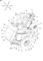
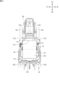
- FIG. 1 is a perspective view showing an embodiment of a work vehicle according to the present disclosure.
- FIG. FIG. FIG. 2 is a side view (right side view) of the work vehicle.
- FIG. 2 is a side view (left side view) of the work vehicle.
- FIG. FIG. 4 is a front view of the second radiator and its surroundings.
- FIG. 4 is a plan view of the second radiator and its surroundings. 4 is a perspective view of the second radiator and its surroundings as viewed diagonally from the rear right.
- FIG. 4 is a perspective view of the second radiator and its surroundings as viewed diagonally from the front left.
- FIG. FIG. 2 is a perspective view of the mounting frame as seen diagonally from the front left.
- FIG. 4 is a side view of the mounting frame and its surroundings as viewed from the left side.
- the objective of this disclosure is to provide a work vehicle that can effectively utilize the space on the vehicle body to arrange electrical equipment that is connected to various electrical components.
- electrical equipment can be arranged by effectively utilizing the space on the vehicle body.
- a work vehicle comprises a vehicle body, a fuel cell mounted on the vehicle body, a driver's seat mounted on the vehicle body horizontally aligned with the fuel cell, and electrical equipment arranged horizontally between the fuel cell and the driver's seat.
- This configuration allows electrical equipment to be arranged in the space between the fuel cell and the driver's seat in a fuel cell-powered work vehicle, and also makes it easier to connect electrical components arranged around the driver's seat to the electrical equipment with cables.
- the work vehicle of (1) above preferably includes a mounting frame disposed horizontally between the fuel cell and the driver's seat, and the electrical equipment is attached to the mounting frame. With this configuration, it is possible to arrange electrical equipment between the fuel cell and the driver's seat.
- the mounting frame is preferably disposed in the center of the vehicle body in a horizontal direction perpendicular to the direction in which the fuel cell and the driver's seat are aligned. This configuration makes it easier to connect electrical components arranged on both sides of the vehicle body in a horizontal direction perpendicular to the direction in which the fuel cell and the driver's seat are aligned with each other, to electrical equipment attached to the mounting frame with cables.
- the work vehicle described in (2) or (3) above preferably includes a radiator arranged horizontally between the fuel cell and the driver's seat, and a support member supporting the radiator, the support member being connected to the mounting frame and the radiator. According to this configuration, the radiator can be supported on the mounting frame via the support member.
- the work vehicle described in any one of (2) to (4) above preferably includes a radiator disposed horizontally between the fuel cell and the driver's seat, and the electrical equipment is attached to the mounting frame at a position higher than the vertical center of the radiator. According to this configuration, the electrical equipment is disposed at a relatively high position, and work on the electrical equipment, such as connecting cables and inspecting the electrical equipment, can be easily performed.
- the work vehicle described in any one of (1) to (5) above preferably includes a radiator disposed horizontally between the fuel cell and the driver's seat, and the electrical equipment is disposed on the air intake side of the radiator. According to this configuration, air having a relatively low temperature before passing through the radiator passes around the electrical equipment, so that a rise in temperature of the electrical equipment can be suppressed.
- the radiator is preferably disposed horizontally between the fuel cell and the electrical equipment, and has a fan that generates an airflow from the electrical equipment side to the fuel cell side.
- electrical components can be disposed on the air intake side of the radiator.
- the work vehicle described in any one of (1) to (7) above preferably includes an air cleaner that purifies the air supplied to the fuel cell, and the electrical equipment and the air cleaner are arranged to overlap in a horizontal direction perpendicular to the direction in which the fuel cell and the driver's seat are aligned.
- the space on the vehicle body can be effectively utilized by arranging the air cleaner together with the electrical equipment horizontally between the fuel cell and the driver's seat.
- both the electrical equipment and the air cleaner can be arranged in the limited space between the fuel cell and the driver's seat.
- the work vehicle described in any one of (1) to (8) above preferably includes a first bonnet covering the fuel cell, and a second bonnet covering the electrical equipment. According to this configuration, when performing maintenance such as inspecting or replacing electrical equipment, it is only necessary to open or remove the second bonnet, thereby improving ease of maintenance.
- the work vehicle described in any one of (1) to (9) above preferably has a cabin arranged around the driver's seat, and the electrical equipment is arranged horizontally between the fuel cell and the cabin. In this way, the space between the fuel cell and the cabin can be effectively utilized to arrange the electrical equipment.
- Fig. 1 is a perspective view showing an embodiment of a work vehicle according to the present disclosure.
- Fig. 2 to Fig. 7 are a front view, a rear view, a side view (right side view), a side view (left side view), a plan view, and a bottom view of the work vehicle shown in Fig. 1.
- the work vehicle 10 of this embodiment is a vehicle that can be used for agricultural work.
- the work vehicle 10 shown in FIG. 1 is a tractor.
- the work vehicle 10 is not limited to a tractor.
- the work vehicle 10 according to the present disclosure may be an agricultural machine other than a tractor, a construction machine, a utility vehicle, etc. Examples of agricultural machines include a harvester, a rice transplanter, a transplanter, a grass cutter, a seeding machine, a fertilizer applicator, etc.
- the directions of the work vehicle 10 disclosed herein are defined below.
- the direction in which the work vehicle 10 moves forward is defined as front
- the direction in which the work vehicle 10 moves backward is defined as rear
- the left side of the work vehicle 10 facing forward is defined as left
- the right side of the work vehicle 10 facing forward is defined as right.
- the left-right direction perpendicular to the fore-aft direction is defined as the vehicle width direction.
- the direction perpendicular to both the fore-aft direction and the vehicle width direction (left-right direction) is defined as the up-down direction.
- the up-down direction is also called the height direction.
- the fore-aft direction and the vehicle width direction are horizontal directions. Therefore, in this specification, the "fore-aft direction" and "vehicle width direction” can be read as the "horizontal direction”.
- the work vehicle 10 shown in FIG. 1 has a vehicle body 11, a running gear 12, a driver's seat 15, a cabin 16, a tank unit 21, and a drive unit 14.
- the running gear 12 supports the vehicle body 11 so that it can run.
- the tank unit 21 has a tank 13 that stores fuel.
- the drive unit 14 drives the work vehicle 10 using the fuel stored in the tank 13.
- the fuel is hydrogen.
- the tank 13 is a hydrogen tank that stores hydrogen gas.
- the work vehicle 10 in this embodiment is a fuel cell vehicle (FCV).
- FCV fuel cell vehicle
- the work vehicle 10 runs on electricity generated by a fuel cell (fuel cell module) 24 using hydrogen and oxygen.
- the drive device 14 includes a fuel cell 24, a battery unit 30, and an electric motor 31.
- the battery unit 30 has a battery 300 that stores the power generated by the fuel cell 24.
- the battery unit 30 supplies the stored power to the motor 31.
- the work vehicle 10 has piping for hydrogen gas (hydrogen piping) 22, and a filling section 25 (see FIG. 3).
- the filling section 25 has a filling port (receptacle) 26.
- a filling nozzle of a hydrogen gas supply device (not shown) that is separate from the work vehicle 10 is connected to the filling port 26.
- Hydrogen gas is supplied from the filling port 26 through the piping 22 (rear piping 22r) to the tank 13.
- the hydrogen gas in the tank 13 is supplied to the fuel cell 24 through the piping 22 (front piping 22f).
- the specific configurations of the filling section 25 and the piping 22 will be described later.
- the work vehicle 10 has a mounting frame 17 and a support structure 37.
- the mounting frame 17 is used to mount the tank unit 21 (tank 13) on the vehicle body 11.
- the support structure 37 is used to support the battery unit 30 on the vehicle body 11.
- the work vehicle 10 has an exhaust path 35.
- the exhaust path 35 exhausts water or water vapor generated by the operation of the fuel cell 24 to the outside. The specific configuration of the mounting frame 17 will be described later.
- FIG. 8 is an exploded perspective view of a part of the work vehicle 10 shown in FIG. 1.
- the chassis 41 is located at the center in the vehicle width direction and has a shape that is long in the front-rear direction.
- the chassis 41 has a front frame 32 that constitutes the front part of the chassis 41, and a gear case 33 that is connected to the rear end of the front frame 32 and constitutes the rear part of the chassis 41.
- the front frame 32 is formed by combining metal frame materials (plate materials, rod materials, etc.).
- the gear case 33 is formed by having a metal box body.
- the gear case 33 is connected to the rear part of the front frame 32, and the gear case 33 and the front frame 32 form the framework of the vehicle body 11.
- the front frame 32 mounts the motor 31.
- the gear case 33 has a power transmission mechanism 333 inside, such as a clutch, transmission, and differential gear.
- the power transmission mechanism 333 slows or speeds up the rotation of the output shaft of the motor 31, and outputs it to the running device 12 (one or both of the front wheels 121 and the rear wheels 122).
- the power transmission mechanism 333 outputs a portion of the power of the motor 31 to the PTO shaft 334 (see FIG. 3).
- the PTO shaft 334 is an output shaft provided at the rear of the gear case 33.
- the work vehicle 10 has a coupling device 43 for coupling another device to the rear of the vehicle body 11.
- the PTO shaft 334 transmits the power of the motor 31 to the other device coupled to the coupling device 43.
- the other device is a work device (not shown), also called an implement.
- the work device is operated by the power of the motor 31.
- the work device is a tiller, etc.
- Figure 9 is a right side view of the work vehicle 10 with the bonnet 34, cover 111, and part of the tank case 211 of the tank unit 21 removed.
- the first radiator 48, fuel cell 24, and second radiator 49 are mounted on the chassis 41, lined up in this order from the front to the rear of the vehicle.
- the first radiator 48, fuel cell 24, and second radiator 49 are located in the center of the vehicle body 11 in the vehicle width direction.
- the bonnet (first bonnet) 34 and the cover (second bonnet) 111 cover the mounted items located toward the front of the vehicle body 11.
- the bonnet 34 covers the fuel cell 24 and the first radiator 48 from above and on both sides in the vehicle width direction.
- the cover 111 covers the second radiator 49 located behind the fuel cell 24 from above and on both sides in the vehicle width direction.
- the top surface 48a of the first radiator 48 is lower than the top surface 24a of the fuel cell 24.
- the top surface 24a of the fuel cell 24 is lower than the top surface 49a of the second radiator 49.
- the front side of the top surface 24a of the fuel cell 24 is inclined diagonally downward toward the front.
- the top surface 111a of the cover 111 is higher than the top surface 34a of the bonnet 34.
- the top surface 111a of the cover 111 is lower than the upper end of the steering wheel 151 that is operated by an operator sitting in the driver's seat 15 to steer.
- the top surface 34a of the bonnet 34 becomes lower toward the front. This makes it less likely that the operator sitting in the driver's seat 15 will have an obstructed view.
- the driver's seat 15 and the cabin 16 are provided on the chassis 41 at a rearward position, particularly on the gear case 33.
- the cabin 16 has the driver's seat 15 inside.
- the cabin 16 is arranged around the driver's seat 15.
- the cabin 16 has a front pillar 162 located forward of the driver's seat 15, a rear pillar 163 located behind the driver's seat 15, and a roof 164 located above the driver's seat 15.
- the front pillar 162 is provided on the left front and right front of the driver's seat 15.
- the rear pillar 163 is provided on the left rear and right rear of the driver's seat 15.
- the roof 164 is supported by the front pillar 162 and the rear pillar 163.
- the cabin 16 has a windshield 165 located in front of the driver's seat 15.
- the windshield 165 is provided between the left and right front pillars 162.
- the cabin 16 has openable and closable doors 166 on both sides in the vehicle width direction.
- the doors 166 are provided between the front pillars 162 and the rear pillars 163.
- a step 167 (see FIG. 5 ) is provided on one side (left side) in the vehicle width direction of the cabin 16.
- the step 167 is a member on which an operator who gets on and off the cabin 16 places his or her feet.
- a cover 111 and a bonnet 34 are provided in front of the cabin 16. As shown in Fig. 2 and Fig. 6, the dimensions of the cover 111 and the bonnet 34 in the vehicle width direction are each smaller than the dimension of the cabin 16 in the vehicle width direction. The dimension of the bonnet 34 in the vehicle width direction is smaller than the dimension of the cover 111 in the vehicle width direction.
- the work vehicle 10 of this embodiment has a cabin 16, but does not necessarily have to have the cabin 16.
- the work vehicle 10 may have a canopy or ropes instead of the cabin 16. If the work vehicle 10 does not have a cabin 16, the tank unit 21 is supported by the mounting frame 17 and positioned above the driver's seat 15.
- the traveling device 12 has front wheels 121 and rear wheels 122 (see FIG. 6 ).
- the front wheels 121 are provided on the left and right sides of the front part of the vehicle body 11.
- the rear wheels 122 are provided on the left and right sides of the rear part of the vehicle body 11.
- the maximum dimension in the vehicle width direction of the left and right rear wheels 122 (the dimension between the outer end in the vehicle width direction of the left rear wheel 122 and the outer end in the vehicle width direction of the right rear wheel 122) is larger than the maximum dimension in the vehicle width direction of the left and right front wheels 121 (the dimension between the outer end in the vehicle width direction of the left front wheel 121 and the outer end in the vehicle width direction of the right front wheel 121).
- the maximum dimension in the vehicle width direction of the left and right rear wheels 122 is the maximum vehicle width dimension of the work vehicle 10.
- One or both of the front wheels 121 and the rear wheels 122 rotate by the power of the motor 31.
- One or both of the front wheels 121 and the rear wheels 122 (drive wheels) that rotate by the power of the motor 31 may be crawlers (crawlers).
- the drive device 14 includes the fuel cell 24 , the battery unit 30 , and the motor 31 .
- the fuel cell 24 is located on the chassis 41 near the front of the vehicle body 11.
- the motor 31 is located behind the fuel cell 24.
- the motor 31 is located in the center of the vehicle body 11 in the vehicle width direction.
- the battery unit 30 is located toward the outside of the vehicle body 11 in the vehicle width direction.
- the battery unit 30 is attached to the chassis 41 by a support structure 37.
- the fuel cell 24 generates electricity using hydrogen gas to obtain the power to rotate the motor 31.
- the fuel cell 24 has a battery casing 241 in the shape of a substantially rectangular box, and a fuel cell stack 242 provided inside the battery casing 241.
- the fuel cell stack 242 has a number of battery cells. Each battery cell has a positive electrode and a negative electrode. The multiple single cells are in a stacked state. The power generated by each battery cell is collected and output to the battery unit 30.
- the motor 31 has a rotating rotor and a stator having multiple coils. As shown in FIG. 8, the output shaft of the motor 31 is connected to a power transmission mechanism 333 in the gear case 33. The motor 31 is located behind the fuel cell 24 and below the second radiator 49.
- the tank unit 21 has a tank (fuel tank) 13 and a tank case 211 that houses the tank 13.
- the tank 13 is a substantially cylindrical high-pressure container.
- the tank 13 is made of fiber-reinforced resin reinforced with carbon fiber or glass fiber, or the like.
- three tanks 13 are fixed to the tank case 211 with the axial direction of their cylindrical portions parallel to the vehicle width direction.
- the number of tanks 13 is not limited to three.
- the tank case 211 is a box capable of housing one or more tanks 13.
- the tank case 211 has a box shape that covers the entire tank 13 it houses.
- the tank case 211 has an opening/closing door 213 (see FIG. 1) on one or both sides in the vehicle width direction, and opens in the vehicle width direction.
- the tank case 211 is installed above the roof 164, spaced apart from the roof 164 in the vertical direction.
- the tank case 211 is fixed to the upper frame portion 171 of the mounting frame 17.
- the tank case 211 is made of metal such as aluminum or steel, and protects the tank 13 from external thermal and physical influences.
- the tank 13 is positioned above the cabin 16 (driver's seat 15). This allows for a high degree of freedom in the placement of the fuel cell 24, charging section 25, motor 31, and battery unit 30 in the vehicle body 11.
- a conventional work vehicle with an internal combustion engine into a work vehicle 10 having a fuel cell 24 and motor 31 as in this embodiment, there is no need to significantly change the placement and configuration of each piece of equipment.
- the tank 13 is connected to the rear pipe 22r and the front pipe 22f (see FIG. 2) via the valve unit 212.
- the rear pipe 22r is a gas inlet pipe that connects the hydrogen gas filling port 26 and the valve unit 212, and guides the hydrogen gas introduced into the filling port 26 to the tank 13.
- the front pipe 22f is a gas outlet pipe that connects the fuel cell 24 and the valve unit 212, and guides the hydrogen gas stored in the tank 13 to the fuel cell 24.
- the tank 13 stores the hydrogen gas introduced into the filling port 26 from outside the vehicle and supplies it to the fuel cell 24.
- the valve unit 212 has an opening/closing valve, a pressure reducing valve, etc., and adjusts the hydrogen gas stored in the tank 13 to a predetermined flow rate and guides it to the fuel cell 24 through the front pipe 22f.
- the mounting frame (support frame) 17 (see FIG. 1 ) is a frame structure for mounting the tank 13 on the vehicle body 11.
- the mounting frame 17 in this embodiment has an upper frame portion 171 that supports the tank 13, and a first front frame portion 172, a second front frame portion 175, and a rear frame portion 173 as frames for supporting the upper frame portion 171.
- a tank case 211 is attached to the upper frame portion 171.
- the upper frame portion 171 supports the tank 13 via the tank case 211.
- the filling section 25 is provided on the rear frame section 173 (see FIG. 3).
- the filling section 25 has a gas filling port 26 to which a gas filling nozzle of a hydrogen gas supply device (not shown) installed outside the vehicle is connected when filling the tank 13 with hydrogen gas.
- the work vehicle 10 (see FIGS. 4 and 5) has a cooling system that uses a coolant to cool the fuel cell 24, the motor 31, the boost circuit 80, the inverter 81, the DC/DC converters 82, 83, etc.
- the work vehicle 10 has a first radiator 48 and a second radiator 49. As shown in FIG. 9, the first radiator 48 is located in front of the fuel cell 24, and the second radiator 49 is located behind the fuel cell 24.
- the first radiator 48 cools devices other than the fuel cell 24.
- the first radiator 48 is connected to the electric components (heat-generating components) that require cooling, such as the motor 31, the boost circuit 80, the inverter 81, and the DC/DC converters 82 and 83, via a first cooling flow path (not shown) that has a circulation pump.
- the first radiator 48 cools the cooling liquid supplied through the first cooling flow path by exchanging heat with the outside air.
- the second radiator 49 cools the fuel cell 24.
- the second radiator 49 is connected to the fuel cell 24 via a second cooling passage (not shown) having a circulation pump.
- the second radiator 49 cools the cooling liquid supplied through the second cooling passage by heat exchange with the outside air.
- the first radiator 48 has a first fan 481.
- the second radiator 49 has a second fan 491.
- the first fan 481 and the second fan 491 rotate to pass air through the first radiator 48 and the second radiator 49, promoting heat exchange with the coolant.
- the first radiator 48 may cool the fuel cell 24, and the second radiator 49 may cool equipment other than the fuel cell 24.
- the battery unit 30 accumulates power to be supplied to the motor 31.
- the battery unit 30 (see FIG. 9 ) has a battery (battery pack) 300 and a housing 307 that houses the battery 300.
- the battery 300 temporarily accumulates power generated by the fuel cell 24 and outputs the accumulated power to electrical equipment (electrical components) such as the motor 31.
- the battery 300 is composed of multiple battery cells.
- the battery 300 is a charge-discharge type secondary battery such as a lithium ion battery or a lead storage battery.
- the work vehicle 10 has a junction box 75.
- the junction box 75 is an electric connection box for relaying and connecting and distributing the electric power output from the battery unit 30.
- the fuel cell 24 is connected to an inverter 81 via a boost circuit (see FIG. 5 ).
- the battery unit 30 is connected to the inverter 81 through a junction box 75.
- the inverter 81 is electrically connected to the motor 31.
- the inverter 81 converts the DC power output from the boost circuit into three-phase AC power and outputs it to the motor 31.
- the work vehicle 10 has low-voltage electrical components that operate at a lower voltage than the motor 31. Electric power stepped down by a step-down circuit is supplied to the low-voltage electrical components through a junction box 75.
- the work vehicle 10 of this embodiment has a battery unit 30, radiators 48, 49, and an air conditioner 74 as the low-voltage electrical components.
- the work vehicle 10 has a first DC/DC converter 82 and a second DC/DC converter 83 as the step-down circuit.
- Fig. 10 is a front view of the second radiator and its surroundings.
- Fig. 11 is a plan view of the second radiator and its surroundings.
- Fig. 12 is a perspective view of the second radiator and its surroundings as viewed from the right rear.
- Fig. 13 is a perspective view of the second radiator and its surroundings as viewed from the left front.
- the second radiator 49 has a radiator body 492 through which the coolant flows, and a fan (second fan) 491 that supplies airflow to the radiator body 492.
- the fan 491 is disposed behind the radiator body 492.
- the fan 491 rotates around an axis C (see FIG. 12) in the front-rear direction, generating an airflow from the back to the front. In other words, it generates an airflow that flows in the direction in which the second radiator 49 and the fuel cell 24 are aligned.
- the cabin 16 is disposed behind the second radiator 49.
- the fan 491 of the second radiator 49 Since the fan 491 of the second radiator 49 generates an airflow that flows from the back to the front, the airflow heated by the radiator body 492 is less likely to flow toward the driver's seat 15, which can prevent the temperature in the cabin 16 from increasing and the driver from feeling uncomfortable.
- the dimension (length) of the second radiator 49 in the vehicle width direction is greater than the dimension (length) of the fuel cell 24 in the vehicle width direction.
- the height of the second radiator 49 is greater than the height of the fuel cell 24. Therefore, the second radiator 49 protrudes in the vehicle width direction and upward direction more than the fuel cell 24.
- the height of the second radiator 49 is greater than the height of the bonnet 34 that covers the fuel cell 24.
- the dimension of the second radiator 49 in the vehicle width direction is approximately the same as the dimension (length) of the bonnet 34 in the vehicle width direction or greater than the dimension of the bonnet 34 in the vehicle width direction.
- the height of the cover 111 that covers the upper side and the sides in the vehicle width direction of the second radiator 49 is greater than the height of the bonnet 34.
- the dimension (length) of the cover 111 in the vehicle width direction is approximately the same as the dimension of the bonnet 34 in the vehicle width direction or greater than the dimension of the bonnet 34 in the vehicle width direction.
- the second radiator 49 has a larger dimension and height in the vehicle width direction than the fuel cell 24, respectively, so the second radiator 49 is enlarged and positioned to protrude outward and upward in the vehicle width direction beyond the fuel cell 24. This makes it difficult for the fuel cell 24 to obstruct the flow of air passing through the second radiator 49. This increases the heat exchange capacity of the second radiator 49 and improves the cooling performance of the fuel cell 24.
- the second radiator 49 has a first hose 493 and a second hose 494 that connect the radiator body 492 and the fuel cell 24.
- the second hose 494 carries the coolant supplied from the radiator body 492 to the fuel cell 24, and the first hose 493 carries the coolant returning from the fuel cell 24 to the radiator body 492.
- One end of the first and second hoses 493, 494 is connected to the front surface of the second radiator 49, and the other end of the first and second hoses 493, 494 is connected to the rear surface of the fuel cell 24. Therefore, the first and second hoses 493, 494 are contained within at least the range of the second radiator 49's dimension in the vehicle width direction. In this embodiment, each hose 493, 494 is contained within the range of the fuel cell 24's dimension in the vehicle width direction.
- the second radiator 49 is supported on the chassis 41 of the vehicle body 11 via a first support member 61.
- the first support member 61 extends obliquely from the side of the front frame 32 of the chassis 41 toward the outside and upward in the vehicle width direction.
- the first support member 61 has a front plate 611 and a rear plate 612, and multiple connection plates 613 that connect the front plate 611 and the rear plate 612, and has a roughly box-like shape with a hollow interior.
- the multiple connection plates 613 connect the front plate 611 and the rear plate 612 at the inside, outside, and upper end in the vehicle width direction.
- the lower surface of the second radiator 49 is mounted on the upper surface of an upper connection plate 613a that connects the upper ends of the front plate 611 and the rear plate 612, and is fixed by fasteners such as bolts.
- the front frame 32 of the chassis 41 is provided with a pair of mounting bases 51 extending outward on both sides in the vehicle width direction. As shown in FIG. 1, the lower end of the first front frame portion 172 of the mounting frame 17 is placed and fixed on these mounting bases 51. The base end of the first support member 61 is also connected to the mounting bases 51. Therefore, the second radiator 49 is also supported by the mounting base 51 that supports the mounting frame 17 via the first support member 61.
- the second radiator 49 is supported from below by a first support member 61 that protrudes upward from the chassis 41, so the second radiator 49 can be easily positioned at a higher position than the fuel cell 24.
- the second radiator 49 is supported by the fuel cell 24 via a second support member 62.
- the second support member 62 is a strip-shaped plate material that is long in the front-to-rear direction.
- the front end of the second support member 62 is connected to the fuel cell 24.
- the rear end of the second support member 62 is connected to the second radiator 49.
- the second support member 62 is provided on both sides of the second radiator 49 and the fuel cell 24 in the vehicle width direction. Therefore, the second radiator 49 is supported from the front by the fuel cell 24 via the second support member 62.
- the connection portion of the second support member 62 to the fuel cell 24 is positioned further inward in the vehicle width direction than the connection portion to the second radiator 49.
- the second support member 62 has a front plate 621 connected to the fuel cell 24, a rear plate 622 connected to the second radiator 49, and an intermediate plate 623 connecting the front plate 621 and the rear plate 622.
- the front plate 621 and the rear plate 622 extend in the front-to-rear direction, and the intermediate plate 623 extends in the vehicle width direction. Therefore, the second support member 62 is formed in an approximately Z-shape when viewed from above.
- a mounting frame (fixing frame) 65 is provided on the chassis 41 behind the second radiator 49. This mounting frame 65 is provided for mounting the cover 111 and electrical components 66.
- Figure 14 is an oblique view of the mounting frame 65 seen from the diagonal front left.
- Figure 15 is a side view of the mounting frame and its surroundings seen from the left side.
- the mounting frame 65 has a base 651, a pair of pillars 652, multiple connecting plates 653, a pair of mounting stays 654, etc.
- the base 651 is formed in a band-like shape and is fixed to the upper surface of the gear case 33 of the chassis 41.
- the pair of pillars 652 are formed in a rod shape.
- the pair of pillars 652 extend upward from the base 651.
- the pair of pillars 652 are arranged side by side with a gap in the vehicle width direction.
- the multiple connecting plates 653 extend in the vehicle width direction and connect the upper ends of the pair of pillars 652 to each other and the middle parts in the up-down direction to each other.
- the pair of mounting stays 654 are formed in a rod shape and extend upward from the upper end connecting plate 653.
- a cover 111 is attached to the tip of the mounting stay 654.
- the second radiator 49 is supported by the mounting frame 65 via a third support member 63.
- the third support members 63 are provided on both sides of the mounting frame 65 in the vehicle width direction.
- Each third support member 63 has an arm portion 631 and a connecting portion 632.
- the arm portion 631 is formed in a plate shape and extends outward in the vehicle width direction from each pillar 652 of the mounting frame 65.
- the connecting portion 632 is plate-shaped and extends forward from the tip of the arm portion 631.
- the connecting portion 632 is connected to the side surface of the second radiator 49 in the vehicle width direction. Therefore, the second radiator 49 is supported from the rear side by the mounting frame 65 via the third support member 63.
- the second support member 62 and the third support member 63 are connected to the middle part of the second radiator 49 in the vertical direction. Therefore, the second radiator 49 is supported from below by the chassis 41 and the mounting base 51 of the vehicle body 11 via the first support member 61, and is supported from the front-rear direction by the fixed members (fuel cell 24, mounting frame 65) fixed to the chassis 41 via the second support member 62 and the third support member 63. Therefore, the second radiator 49 is firmly supported from three sides, below, front, and rear. Since the second radiator 49 is supported from the front and rear by the second support member 62 and the third support member 63, the second radiator 49 can be stably supported against front-rear forces associated with the travel of the work vehicle 10, such as inertial forces associated with acceleration and deceleration.
- the electrical components 66 are attached to the mounting frame 65.
- the electrical components 66 include, for example, fuses, relays, terminal blocks, and control components (CPU, control board, etc.). Cables are connected to the electrical components 66.
- the mounting frame 65 is disposed between the fuel cell 24 and the cabin 16 (driver's seat 15) in the fore-and-aft direction.
- the mounting frame 65 is also disposed between the second radiator 49 and the cabin 16 (driver's seat 15) in the fore-and-aft direction. Therefore, the electrical equipment 66 is also disposed between the fuel cell 24 and the second radiator 49 and the cabin 16 (driver's seat 15) in the fore-and-aft direction.
- the mounting frame 65 and the electrical equipment 66 are disposed in front of the windshield 165 of the cabin 16.
- a plurality of electrical components 66 are attached to the mounting frame 65.
- the plurality of electrical components 66 are attached to one or a plurality of connection plates 653.
- the electrical components 66 are disposed at a position lower than the upper surface (upper end) 49a of the second radiator 49.
- the electrical components 66 are disposed at a position higher than the lower end 49b of the second radiator 49.
- the electrical components 66 are disposed at a position higher than the rotation axis C of the fan 491.
- the electrical equipment 66 is disposed below the cover 111 and at least a portion of it is covered by the cover 111.
- the electrical equipment 66 is disposed at a position substantially the same height as the upper surface (upper end) 24a of the fuel cell 24 or higher.
- the electrical equipment 66 is disposed at a position lower than the upper surface (upper end) 34a of the bonnet 34 that covers the fuel cell 24.
- the front end of the cover 111 overlaps above the rear end of the bonnet 34.
- a pair of columns 652 of the mounting frame 65 have a lower portion 652a, an intermediate portion 652b connected to the upper end of the lower portion 652a, and an upper portion 652c connected to the upper end of the intermediate portion 652b.
- the lower portion 652a is arranged vertically.
- the intermediate portion 652b is inclined rearward from the lower end to the upper end.
- the upper portion 652c is arranged vertically.
- the electrical equipment 66 is attached to a connecting plate 653 at the upper end that connects the upper portions 652c of the pair of columns 652. Therefore, as shown in FIG. 15, the electrical equipment 66 is arranged rearward of the lower portion 652a connected to the base 651. As a result, the electrical equipment 66 is closer to the cabin 16 than the fan 491. Therefore, a relatively wide space S is formed between the electrical equipment 66 and the fan 491 in the front-rear direction. This space S can be used, for example, as a space for arranging cables connected to the electrical equipment 66.
- the electrical equipment 66 is disposed between the fuel cell 24 and second radiator 49 and the driver's seat 15 and cabin 16 in the fore-and-aft direction. This allows the electrical components in the cabin 16 to be closer to the electrical equipment 66, improving connectivity between the two via cables.
- the mounting frame 65 also positions the electrical equipment 66 at a relatively high position, for example, above the vertical center of the second radiator 49 (for example, the position of the axis C of the fan 491). This allows for improved connectivity of cables to the electrical equipment 66, and also improves the ease of maintenance, such as inspection and replacement, of the electrical equipment 66.
- the inverter 81 and the DCDC converters 82 and 83 are connected to the electrical equipment 66 via cables.
- the inverter 81 and the DCDC converters 82 and 83 are disposed below the cabin 16, in a position offset to one side (left) in the vehicle width direction from the chassis 41.
- the junction box 75 is disposed on the lower front side of the cabin 16, in a position offset to one side (right) in the vehicle width direction from the chassis 41.
- the junction box 75 is disposed between the cabin 16 (driver's seat 15) and the fuel cell 24 in the fore-and-aft direction, in a position overlapping (aligned in the vehicle width direction) with the second radiator 49 and the mounting frame 65.
- the mounting frame 65 and the electrical equipment 66 are positioned in the center of the vehicle body 11 in the vehicle width direction. This improves the cable connectivity between the electrical components 81, 82, 83, and 75, which are positioned on both the left and right sides of the vehicle body 11, and the electrical equipment 66.
- the fan 491 of the second radiator 49 generates an airflow from back to front.
- the electrical equipment 66 is disposed behind the second radiator 49, i.e., on the air intake side of the second radiator 49. Therefore, outside air, which has a relatively low temperature before heat exchange, flows around the electrical equipment 66, suppressing the temperature rise of the electrical equipment 66. Furthermore, if the electrical equipment 66 is a heat-generating component such as a relay, the cooling of the electrical equipment 66 can be promoted.
- the work vehicle 10 is equipped with an air cleaner 68.
- the air cleaner 68 purifies the air supplied to the fuel cell 24.
- the air cleaner 68 has a cleaner body 681 formed in a substantially cylindrical shape, an intake port 682 that takes in air into the cleaner body 681, and an exhaust port 683 that exhausts air from the cleaner body 681.
- One end of an exhaust hose 69 is connected to the exhaust port 683.
- the other end of the exhaust hose 69 is connected to the fuel cell 24.
- the cleaner body 681 is arranged with the axis of the cylindrical shape facing the vertical direction.
- the dimensions of the cleaner body 681 in the front-rear direction and the vehicle width direction are smaller than the dimensions in the vertical direction.
- the discharge port 683 is arranged on the upper surface of the cleaner body 681. This makes it easy to connect the discharge hose 69 to the discharge port 683.
- the intake 682 is located at the lower end of the outer circumferential surface of the cleaner body 681.
- the intake 682 is formed in a short tube shape, protrudes diagonally downward and outward in the vehicle width direction from the outer circumferential surface of the cleaner body 681, and opens diagonally downward. This prevents foreign matter such as dust from entering the intake 682.
- the intake 682 may open downward (straight below) instead of diagonally downward.
- the air cleaner 68 is disposed between the fuel cell 24 and the cabin 16 (driver's seat 15) in the front-rear direction. More specifically, the air cleaner 68 is disposed between the second radiator 49 and the cabin 16 (driver's seat 15) in the front-rear direction. The air cleaner 68 is disposed outside the chassis 41 in the vehicle width direction. The air cleaner 68 is disposed within the vehicle width dimension of the second radiator 49. The air cleaner 68 and the mounting frame 65 are disposed side by side in the vehicle width direction.
- the air cleaner 68 is disposed in front of the left arm portion 631, which is the third support member 63, and on the inside (right side) of the left connecting portion 632 in the vehicle width direction.
- the air cleaner 68 is attached to and supported by the third support member 63. Therefore, the air cleaner 68 is supported by the second radiator 49 and the mounting frame 65 via the third support member 63.
- the air cleaner 68 is arranged with the axis of the cylinder facing up and down. This allows the installation space in the front-rear and width directions of the vehicle to be reduced. This allows the air cleaner 68 to be arranged in the narrow space between the second radiator 49 and the cabin 16 in the front-rear direction.
- the air cleaner 68 can also be arranged in the narrow space between the third support member 63 and the chassis 41 in the width direction of the vehicle.
- the exhaust hose 69 extends diagonally downward and forward from the exhaust port 683 of the air cleaner 68.
- the exhaust hose 69 is arranged across the outer side of the second radiator 49 in the vehicle width direction from the air cleaner 68 behind the second radiator 49 to the fuel cell 24 in front of the second radiator 49.
- the exhaust hose 69 is arranged outside the connecting portion 632 of the third support member 63 in the vehicle width direction.
- the exhaust hose 69 may be supported by the third support member 63.
- the exhaust hose 69 extends in the vehicle width direction passing between the second radiator 49 and the fuel cell 24 in the front-rear direction, and is connected to the rear surface of the fuel cell 24.
- the air cleaner 68 is located behind the second radiator 49, i.e., on the air intake side of the second radiator 49. This allows relatively low-temperature, clean air to be taken in by the air cleaner 68 before it passes through the second radiator 49.
- the cover 111 covers the top and sides in the vehicle width direction of the second radiator 49.
- the cover 111 has a first cover member 111b and a second cover member 111c.
- the first cover member 111b covers the right side, the top, and the upper left side of the second radiator 49.
- the second cover member 111c covers the lower left side of the second radiator 49.
- the first cover member 111b and the second cover member 111c are separated into an upper and lower part with the exhaust hose 69 in between. Therefore, a part of the exhaust hose 69 is exposed to the outside.
- the lower edge 111b1 of the part of the first cover member 111b that covers the left side surface of the second radiator 49 and the upper edge 111c1 of the second cover member 111c are formed to incline diagonally downward and forward along the exhaust hose 69.
- the cover 111 covers not only the second radiator 49, but also the air cleaner 68, the mounting frame 65, and the electrical equipment 66.
- the first cover member 111b is attached to and supported by the third support member 63 and the mounting frame 65 (mounting stay 654).
- the second cover member 111c is attached to and supported by the third support member 63.
- the work vehicle 10 of this embodiment includes the vehicle body 11, the fuel cell 24 mounted on the vehicle body 11, the driver's seat 15 mounted on the vehicle body 11 aligned in the fore-and-aft direction with the fuel cell 24, an air cleaner 68 that purifies the air supplied to the fuel cell 24, and electrical equipment 66.
- the air cleaner 68 and the electrical equipment 66 are arranged between the fuel cell 24 and the driver's seat 15 in the fore-and-aft direction.
- the work vehicle 10 of this embodiment also has a cabin 16 arranged around the driver's seat 15, and the air cleaner 68 and the electrical equipment 66 are arranged between the fuel cell 24 and the cabin 16 in the fore-and-aft direction. Therefore, the air cleaner 68 and the electrical equipment 66 can be arranged by effectively utilizing the space between the fuel cell 24 and the driver's seat 15 and the cabin 16.
- the vehicle body 11 of this embodiment includes a bonnet (first bonnet) 34 that covers the fuel cell 24, and a cover (second bonnet) 111 that covers the second radiator 49, the air cleaner 68, and the electrical equipment 66. Therefore, when performing maintenance such as inspection or replacement of the second radiator 49, the air cleaner 68, and the electrical equipment 66, it is only necessary to open or remove the cover 111, improving maintainability.
- the work vehicle 10 of this embodiment includes a mounting frame 65 arranged between the fuel cell 24 and the cabin 16 (driver's seat 15) in the fore-and-aft direction, and electrical equipment 66 is attached to the mounting frame 65. This makes it possible to arrange the electrical equipment 66 between the fuel cell 24 and the driver's seat 15.
- the electrical equipment 66 and the air cleaner 68 are positioned so that they overlap in the vehicle width direction. Therefore, both the electrical equipment 66 and the air cleaner 68 can be placed in the narrow space in the front-rear direction between the fuel cell 24 and the cabin 16.
- the fuel cell 24 may be arranged side by side behind the cabin 16 and the driver's seat 15.
- the second radiator 49, the air cleaner 68, and the electrical equipment 66 are arranged behind the cabin 16 and the driver's seat 15 and in front of the fuel cell 24.
- the fuel cell 24, the cabin 16, and the driver's seat 15 may be arranged side by side in the vehicle width direction, with the second radiator 49, the air cleaner 68, the mounting frame 65, the electrical equipment 66, etc., arranged between them.
Landscapes
- Engineering & Computer Science (AREA)
- Life Sciences & Earth Sciences (AREA)
- Sustainable Development (AREA)
- Sustainable Energy (AREA)
- Power Engineering (AREA)
- Transportation (AREA)
- Mechanical Engineering (AREA)
- Fuel Cell (AREA)
- Arrangement Or Mounting Of Propulsion Units For Vehicles (AREA)
Abstract
Description
例えば、特許文献1には、車体上に運転席及びボンネットを搭載し、ボンネット内に燃料電池とともに燃料電池で発電した電気を蓄積するバッテリや電動モータを制御するコントローラを収容した作業車両が開示されている。
燃料電池を搭載した作業車両においては、バッテリやコントローラだけでなく、燃料電池を冷却するラジエータや、燃料電池に供給される空気を清浄化するエアクリーナ、バッテリやコントローラに接続される各種の電装品等が必要であり、これらを車体上の限られたスペースに適正に配置することが求められる。
本開示によれば、車体上のスペースを有効に利用して電装品を配置することができる。
以下、本開示の実施形態の概要を列記して説明する。
(1)本開示の実施形態に係る作業車両は、車体と、前記車体に搭載された燃料電池と、前記燃料電池と水平方向に並べて前記車体に搭載された運転席と、前記燃料電池と前記運転席との水平方向の間に配置された電装品と、を備える。
この構成によれば、燃料電池によって駆動される作業車両において、燃料電池と運転席との間のスペースを有効に使用して電装品を配置することができる。また、運転席の周囲に配置された電気部品を電装品にケーブルで接続しやすくすることができる。
このような構成によって、燃料電池と運転席との間に電装品を配置することが可能となる。
この構成によれば、燃料電池と運転席とが並ぶ方向に直交する水平方向において車体の両側に配置された電気部品と、取付フレームに取り付けられた電装品とをケーブルで接続しやすくすることができる。
この構成によれば、支持部材を介して取付フレームにラジエータを支持することができる。
この構成によれば、電装品が比較的高い位置に配置され、電装品に対する作業、例えばケーブルの接続や点検等の作業を容易に行うことができる。
この構成によれば、電装品の周辺にはラジエータを通過する前の比較的低温の空気が通過するので、電装品の昇温を抑制することができる。
このような構成によって、ラジエータにおける空気の吸込み側に電装品を配置することができる。
この構成によれば、燃料電池と運転席との水平方向の間に電装品とともにエアクリーナを配置することで、車体上のスペースを有効に利用することができる。特に、電装品とエアクリーナとを、燃料電池と運転席とが並ぶ方向に直交する水平方向に重複して配置することで、電装品とエアクリーナとの双方を燃料電池と運転席との間の限られたスペースに配置することができる。
この構成によれば、電装品の点検や交換等のメンテナンスを行う際に第二ボンネットのみを開けたり取り外したりすればよく、メンテナンス性を高めることができる。
このように、燃料電池とキャビンとの間のスペースを有効に利用して電装品を配置することができる。
[作業車両の全体構成]
図1は、本開示の作業車両の実施の一形態を示す斜視図である。図2から図7は、図1に示す作業車両の正面図、背面図、側面図(右側面図)、側面図(左側面図)、平面図、及び底面図である。
本実施形態の作業車両10は、農作業に用いることが可能である車両である。図1に示す作業車両10は、トラクタである。作業車両10は、トラクタに限定されない。例えば、本開示にかかる作業車両10は、トラクタ以外の農業機械、建設機械、ユーティリティビーグル等であってもよい。農業機械としては、例えば、収穫機、田植機、移植機、草刈機、播種機、施肥機等が挙げられる。
車体11は、シャーシ41、ボンネット34、カバー111、及びフェンダ47を有する。フェンダ47は、後輪122を上から覆う。
シャーシ41は、走行装置12、駆動装置14、及びキャビン16を支持する。図8は、図1に示す作業車両10の一部を分解して示す斜視図である。シャーシ41は、車幅方向の中央に位置し、前後方向に長い形状を有する。シャーシ41は、シャーシ41の前部を構成する前フレーム32と、前フレーム32の後端に連結され、シャーシ41の後部を構成するギアケース33とを有する。前フレーム32は、金属製のフレーム材(板材、棒材等)などを組み合わせて構成される。ギアケース33は、金属製の箱体を有して構成される。ギアケース33は、前フレーム32の後部と結合されていて、ギアケース33と前フレーム32とにより車体11の骨格が形成される。
図1に示すように、運転席15及びキャビン16は、シャーシ41の上であって後ろ寄りの位置、特にギアケース33上に設けられている。キャビン16は、運転席15を内部に有する。キャビン16は、運転席15の周囲に配置される。キャビン16は、運転席15よりも前方に位置する前柱162と、運転席15よりも後ろに位置する後ろ柱163と、運転席15よりも上に位置するルーフ164とを有する。前柱162は、運転席15の左前方及び右前方に設けられている。後ろ柱163は、運転席15の左後方及び右後方に設けられている。ルーフ164は、前柱162及び後ろ柱163によって支持される。
キャビン16の前に、カバー111及びボンネット34が設けられる。図2及び図6に示すように、カバー111及びボンネット34それぞれの車幅方向の寸法は、キャビン16の車幅方向の寸法よりも小さい。ボンネット34の車幅方向の寸法は、カバー111の車幅方向の寸法よりも小さい。
走行装置12は、前輪121と後輪122とを有する(図6参照)。前輪121は、車体11の前部の左右に設けられている。後輪122は、車体11の後部の左右に設けられている。左右の後輪122の車幅方向の最大寸法(左の後輪122の車幅方向外端と右の後輪122の車幅方向外端との間の寸法)は、左右の前輪121の車幅方向の最大寸法(左の前輪121の車幅方向外端と右の前輪121の車幅方向外端との間の寸法)よりも大きい。左右の後輪122の車幅方向の最大寸法が、作業車両10の最大車幅寸法となる。
前記のとおり、駆動装置14は、燃料電池24、電池ユニット30、及びモータ31を有する。
図9に示すように、燃料電池24は、車体11の前寄りにおいて、シャーシ41の上に位置する。図8に示すように、モータ31は、燃料電池24の後ろに位置する。モータ31は、車体11の車幅方向の中央に位置する。図1に示すように、電池ユニット30は、車体11の車幅方向の外側寄りに位置する。電池ユニット30は、支持構造体37によって、シャーシ41に取り付けられる。
図9に示すように、タンクユニット21は、タンク(燃料タンク)13と、タンク13を収容するタンクケース211とを有する。タンク13は、略円筒状の高圧容器である。タンク13は、炭素繊維又はガラス繊維により強化された繊維強化樹脂等によって構成される。本実施形態の場合、3つのタンク13が、その円筒部の軸方向を車幅方向に平行にした状態でタンクケース211に固定されている。タンク13の数は、3つに限定されない。
搭載フレーム(支持フレーム)17は(図1参照)、車体11にタンク13を搭載するためのフレーム構造体である。本実施形態の搭載フレーム17は、タンク13を支持する上フレーム部171と、上フレーム部171を支持するためのフレームとして、第一前フレーム部172、第二前フレーム部175、及び後ろフレーム部173を有する。本実施形態の場合、上フレーム部171に、タンクケース211が取り付けられている。つまり、上フレーム部171は、タンクケース211を介してタンク13を支持する。
作業車両10は(図4及び図5参照)、燃料電池24、モータ31、昇圧回路80、インバータ81、DC/DCコンバータ82,83等を冷却液により冷却させる冷却システムを有する。前記冷却システムの一部として、作業車両10は、第一ラジエータ48と、第二ラジエータ49とを有する。図9に示すように、第一ラジエータ48は、燃料電池24の前に位置し、第二ラジエータ49は、燃料電池24の後ろに位置する。
電池ユニット30は、モータ31に供給する電力を蓄積する。電池ユニット30は(図9参照)、電池(バッテリパック)300と、電池300を収容する筐体307とを有する。電池300は、燃料電池24が発生する電力を一時的に蓄え、その蓄えた電力をモータ31等の電機品(電気部品)に出力する。電池300は、複数の電池セルにより構成される。電池300は、リチウムイオン電池又は鉛蓄電池等の充放電型の二次電池である。
作業車両10は、ジャンクションボックス75を有する。ジャンクションボックス75は、電池ユニット30から出力される電力の中継接続、及び分配を行うための電気接続箱である。
燃料電池24は、昇圧回路を介してインバータ81に接続されている(図5参照)。電池ユニット30は、ジャンクションボックス75を通じて、インバータ81に接続されている。インバータ81は、モータ31と電気的に接続される。インバータ81は、昇圧回路から出力される直流電力を三相交流電力に変換してモータ31に出力する。
図10は、第二ラジエータ及びその周囲の正面図である。図11は、第二ラジエータ及びその周囲の平面図である。図12は、第二ラジエータ及びその周囲を右斜め後ろから見た斜視図である。図13は、第二ラジエータ及びその周囲を左斜め前から見た斜視図である。
取付フレーム65には、電装品66が取り付けられている。電装品66は、例えば、ヒューズ、リレー、端子台、制御部品(CPU、制御基板等)である。これらの電装品66には、ケーブルが接続される。
図11、図12、及び図13に示すように、作業車両10は、エアクリーナ68を備えている。エアクリーナ68は、燃料電池24に供給される空気を清浄化する。エアクリーナ68は、略円筒形状に形成されたクリーナ本体681と、クリーナ本体681内に空気を取り入れる取入口682と、クリーナ本体681から空気を排出する排出口683とを有する。排出口683には、排出ホース69の一端が接続されている。排出ホース69の他端は、燃料電池24に接続されている。
例えば、燃料電池24は、キャビン16及び運転席15の後方に並べて配置されていてもよい。この場合、第二ラジエータ49、エアクリーナ68、及び電装品66は、キャビン16及び運転席15の後ろであって燃料電池24の前に配置される。燃料電池24とキャビン16及び運転席15とは、車幅方向に並べて配置され、これらの間に第二ラジエータ49、エアクリーナ68、取付フレーム65、電装品66等が配置されていてもよい。
11 :車体
15 :運転席
16 :キャビン
24 :燃料電池
34 :ボンネット(第一ボンネット)
49 :第二ラジエータ
65 :取付フレーム
66 :電装品
68 :エアクリーナ
75 :ジャンクションボックス(電気部品)
81 :インバータ(電気部品)
82 :第一DC/DCコンバータ(電気部品)
83 :第二DC/DCコンバータ(電気部品)
111 :カバー(第二ボンネット)
Claims (10)
- 車体と、前記車体に搭載された燃料電池と、前記燃料電池と水平方向に並べて前記車体に搭載された運転席と、前記燃料電池と前記運転席との水平方向の間に配置された電装品と、を備える、作業車両。
- 前記燃料電池と前記運転席との水平方向の間に配置された取付フレームを備え、前記電装品が前記取付フレームに取り付けられる、請求項1に記載の作業車両。
- 前記燃料電池と前記運転席とが並ぶ方向に直交する水平方向において、前記取付フレームが前記車体の中央部に配置されている、請求項2に記載の作業車両。
- 前記燃料電池と前記運転席との水平方向の間に配置されるラジエータと、前記ラジエータを支持する支持部材と、を備え、前記支持部材が前記取付フレームと前記ラジエータとに接続される、請求項2又は3に記載の作業車両。
- 前記燃料電池と前記運転席との水平方向の間に配置されるラジエータを備え、前記電装品が、前記ラジエータの上下方向の中央よりも高い位置で前記取付フレームに取り付けられる、請求項2~4のいずれか1項に記載の作業車両。
- 前記燃料電池と前記運転席との水平方向の間に配置されるラジエータを備え、前記電装品が、前記ラジエータにおける空気の吸い込み側に配置されている、請求項1~5のいずれか1項に記載の作業車両。
- 前記ラジエータが、前記燃料電池と前記電装品との水平方向の間に配置され、前記電装品側から前記燃料電池側への空気流を生成するファンを有する、請求項6に記載の作業車両。
- 前記燃料電池に供給する空気を清浄化するエアクリーナを備え、前記電装品と前記エアクリーナとが、前記燃料電池と前記運転席とが並ぶ方向に直交する水平方向に重複して配置されている、請求項1~7のいずれか1項に記載の作業車両。
- 前記燃料電池を覆う第一ボンネットと、前記電装品を覆う第二ボンネットと、を備える、請求項1~8のいずれか1項に記載の作業車両。
- 前記運転席の周囲に配置されたキャビンを有し、前記電装品が、前記燃料電池と前記キャビンとの水平方向の間に配置される、請求項1~9のいずれか1項に記載の作業車両。
Priority Applications (3)
| Application Number | Priority Date | Filing Date | Title |
|---|---|---|---|
| EP24831552.5A EP4737174A1 (en) | 2023-06-30 | 2024-05-29 | Work vehicle |
| JP2025529560A JPWO2025004682A1 (ja) | 2023-06-30 | 2024-05-29 | |
| US19/409,015 US20260084547A1 (en) | 2023-06-30 | 2025-12-04 | Work vehicle |
Applications Claiming Priority (2)
| Application Number | Priority Date | Filing Date | Title |
|---|---|---|---|
| JP2023107644 | 2023-06-30 | ||
| JP2023-107644 | 2023-06-30 |
Related Child Applications (1)
| Application Number | Title | Priority Date | Filing Date |
|---|---|---|---|
| US19/409,015 Continuation US20260084547A1 (en) | 2023-06-30 | 2025-12-04 | Work vehicle |
Publications (1)
| Publication Number | Publication Date |
|---|---|
| WO2025004682A1 true WO2025004682A1 (ja) | 2025-01-02 |
Family
ID=93938350
Family Applications (1)
| Application Number | Title | Priority Date | Filing Date |
|---|---|---|---|
| PCT/JP2024/019721 Ceased WO2025004682A1 (ja) | 2023-06-30 | 2024-05-29 | 作業車両 |
Country Status (4)
| Country | Link |
|---|---|
| US (1) | US20260084547A1 (ja) |
| EP (1) | EP4737174A1 (ja) |
| JP (1) | JPWO2025004682A1 (ja) |
| WO (1) | WO2025004682A1 (ja) |
Citations (10)
| Publication number | Priority date | Publication date | Assignee | Title |
|---|---|---|---|---|
| JP2002225577A (ja) * | 2001-02-05 | 2002-08-14 | Iseki & Co Ltd | トラクタ |
| JP2011088571A (ja) * | 2009-10-23 | 2011-05-06 | Iseki & Co Ltd | 作業車両のフロント補器の配置構成 |
| JP2014151722A (ja) * | 2013-02-07 | 2014-08-25 | Toyota Industries Corp | 産業車両 |
| JP2016030579A (ja) * | 2014-07-30 | 2016-03-07 | ヤンマー株式会社 | 作業車両 |
| CN210149159U (zh) * | 2019-06-04 | 2020-03-17 | 武汉海亿新能源科技有限公司 | 一种基于燃料电池的农用拖拉机 |
| JP2020157924A (ja) * | 2019-03-26 | 2020-10-01 | ヤンマーパワーテクノロジー株式会社 | 作業車両 |
| KR102339926B1 (ko) * | 2021-08-20 | 2021-12-17 | 충남대학교산학협력단 | 수소연료전지 구동 승용 관리기 |
| KR20230005526A (ko) * | 2021-07-01 | 2023-01-10 | 현대자동차주식회사 | 차량용 프런트 엔드 모듈 |
| JP2023013186A (ja) * | 2021-07-15 | 2023-01-26 | 株式会社クボタ | 作業機 |
| JP2023013187A (ja) | 2021-07-15 | 2023-01-26 | 株式会社クボタ | 燃料電池システム及びそれを備えた作業機、並びに燃料電池システムの制御方法 |
-
2024
- 2024-05-29 WO PCT/JP2024/019721 patent/WO2025004682A1/ja not_active Ceased
- 2024-05-29 EP EP24831552.5A patent/EP4737174A1/en active Pending
- 2024-05-29 JP JP2025529560A patent/JPWO2025004682A1/ja active Pending
-
2025
- 2025-12-04 US US19/409,015 patent/US20260084547A1/en active Pending
Patent Citations (10)
| Publication number | Priority date | Publication date | Assignee | Title |
|---|---|---|---|---|
| JP2002225577A (ja) * | 2001-02-05 | 2002-08-14 | Iseki & Co Ltd | トラクタ |
| JP2011088571A (ja) * | 2009-10-23 | 2011-05-06 | Iseki & Co Ltd | 作業車両のフロント補器の配置構成 |
| JP2014151722A (ja) * | 2013-02-07 | 2014-08-25 | Toyota Industries Corp | 産業車両 |
| JP2016030579A (ja) * | 2014-07-30 | 2016-03-07 | ヤンマー株式会社 | 作業車両 |
| JP2020157924A (ja) * | 2019-03-26 | 2020-10-01 | ヤンマーパワーテクノロジー株式会社 | 作業車両 |
| CN210149159U (zh) * | 2019-06-04 | 2020-03-17 | 武汉海亿新能源科技有限公司 | 一种基于燃料电池的农用拖拉机 |
| KR20230005526A (ko) * | 2021-07-01 | 2023-01-10 | 현대자동차주식회사 | 차량용 프런트 엔드 모듈 |
| JP2023013186A (ja) * | 2021-07-15 | 2023-01-26 | 株式会社クボタ | 作業機 |
| JP2023013187A (ja) | 2021-07-15 | 2023-01-26 | 株式会社クボタ | 燃料電池システム及びそれを備えた作業機、並びに燃料電池システムの制御方法 |
| KR102339926B1 (ko) * | 2021-08-20 | 2021-12-17 | 충남대학교산학협력단 | 수소연료전지 구동 승용 관리기 |
Also Published As
| Publication number | Publication date |
|---|---|
| EP4737174A1 (en) | 2026-05-06 |
| US20260084547A1 (en) | 2026-03-26 |
| JPWO2025004682A1 (ja) | 2025-01-02 |
Similar Documents
| Publication | Publication Date | Title |
|---|---|---|
| JP7769113B2 (ja) | 作業車両 | |
| JP2019147423A (ja) | 電気駆動車両構造 | |
| JP2026022653A (ja) | 作業車両 | |
| WO2024004915A1 (ja) | 農業用作業車両 | |
| JP2025006700A (ja) | 作業車両 | |
| WO2025004670A1 (ja) | 作業車両 | |
| WO2025004676A1 (ja) | 作業車両 | |
| JP7755745B2 (ja) | 作業車両 | |
| WO2025004673A1 (ja) | 作業車両 | |
| US20260084547A1 (en) | Work vehicle | |
| WO2024004905A1 (ja) | 作業車両 | |
| EP4737168A1 (en) | Work vehicle | |
| JP2025102031A (ja) | 作業車両 | |
| JP2025006682A (ja) | 作業車両 | |
| WO2025004529A1 (ja) | 作業車両 | |
| JP7801447B2 (ja) | 作業車両 | |
| US20250296429A1 (en) | Working vehicle | |
| EP4737151A1 (en) | Work vehicle | |
| WO2025142002A1 (ja) | 作業機械、及び作業車両 | |
| JP7797372B2 (ja) | 作業車両 | |
| JP2025009259A (ja) | 作業車両 | |
| JP2024095105A (ja) | 作業車両 | |
| US20260084520A1 (en) | Work vehicle | |
| WO2025004578A1 (ja) | 作業車両 | |
| WO2025004577A1 (ja) | 作業車両 |
Legal Events
| Date | Code | Title | Description |
|---|---|---|---|
| 121 | Ep: the epo has been informed by wipo that ep was designated in this application |
Ref document number: 24831552 Country of ref document: EP Kind code of ref document: A1 |
|
| ENP | Entry into the national phase |
Ref document number: 2025529560 Country of ref document: JP Kind code of ref document: A |
|
| WWE | Wipo information: entry into national phase |
Ref document number: 2024831552 Country of ref document: EP |
|
| NENP | Non-entry into the national phase |
Ref country code: DE |
|
| ENP | Entry into the national phase |
Ref document number: 2024831552 Country of ref document: EP Effective date: 20260130 |
|
| ENP | Entry into the national phase |
Ref document number: 2024831552 Country of ref document: EP Effective date: 20260130 |
|
| WWP | Wipo information: published in national office |
Ref document number: 2024831552 Country of ref document: EP |