WO2025004510A1 - インペラ - Google Patents
インペラ Download PDFInfo
- Publication number
- WO2025004510A1 WO2025004510A1 PCT/JP2024/015818 JP2024015818W WO2025004510A1 WO 2025004510 A1 WO2025004510 A1 WO 2025004510A1 JP 2024015818 W JP2024015818 W JP 2024015818W WO 2025004510 A1 WO2025004510 A1 WO 2025004510A1
- Authority
- WO
- WIPO (PCT)
- Prior art keywords
- impeller
- recess
- annular portion
- resin
- molten resin
- Prior art date
- Legal status (The legal status is an assumption and is not a legal conclusion. Google has not performed a legal analysis and makes no representation as to the accuracy of the status listed.)
- Ceased
Links
Images



Classifications
-
- B—PERFORMING OPERATIONS; TRANSPORTING
- B29—WORKING OF PLASTICS; WORKING OF SUBSTANCES IN A PLASTIC STATE IN GENERAL
- B29C—SHAPING OR JOINING OF PLASTICS; SHAPING OF MATERIAL IN A PLASTIC STATE, NOT OTHERWISE PROVIDED FOR; AFTER-TREATMENT OF THE SHAPED PRODUCTS, e.g. REPAIRING
- B29C33/00—Moulds or cores; Details thereof or accessories therefor
- B29C33/42—Moulds or cores; Details thereof or accessories therefor characterised by the shape of the moulding surface, e.g. ribs or grooves
-
- B—PERFORMING OPERATIONS; TRANSPORTING
- B29—WORKING OF PLASTICS; WORKING OF SUBSTANCES IN A PLASTIC STATE IN GENERAL
- B29C—SHAPING OR JOINING OF PLASTICS; SHAPING OF MATERIAL IN A PLASTIC STATE, NOT OTHERWISE PROVIDED FOR; AFTER-TREATMENT OF THE SHAPED PRODUCTS, e.g. REPAIRING
- B29C45/00—Injection moulding, i.e. forcing the required volume of moulding material through a nozzle into a closed mould; Apparatus therefor
- B29C45/14—Injection moulding, i.e. forcing the required volume of moulding material through a nozzle into a closed mould; Apparatus therefor incorporating preformed parts or layers, e.g. injection moulding around inserts or for coating articles
-
- B—PERFORMING OPERATIONS; TRANSPORTING
- B29—WORKING OF PLASTICS; WORKING OF SUBSTANCES IN A PLASTIC STATE IN GENERAL
- B29C—SHAPING OR JOINING OF PLASTICS; SHAPING OF MATERIAL IN A PLASTIC STATE, NOT OTHERWISE PROVIDED FOR; AFTER-TREATMENT OF THE SHAPED PRODUCTS, e.g. REPAIRING
- B29C45/00—Injection moulding, i.e. forcing the required volume of moulding material through a nozzle into a closed mould; Apparatus therefor
- B29C45/17—Component parts, details or accessories; Auxiliary operations
- B29C45/26—Moulds
-
- B—PERFORMING OPERATIONS; TRANSPORTING
- B29—WORKING OF PLASTICS; WORKING OF SUBSTANCES IN A PLASTIC STATE IN GENERAL
- B29C—SHAPING OR JOINING OF PLASTICS; SHAPING OF MATERIAL IN A PLASTIC STATE, NOT OTHERWISE PROVIDED FOR; AFTER-TREATMENT OF THE SHAPED PRODUCTS, e.g. REPAIRING
- B29C45/00—Injection moulding, i.e. forcing the required volume of moulding material through a nozzle into a closed mould; Apparatus therefor
- B29C45/17—Component parts, details or accessories; Auxiliary operations
- B29C45/26—Moulds
- B29C45/27—Sprue channels ; Runner channels or runner nozzles
-
- F—MECHANICAL ENGINEERING; LIGHTING; HEATING; WEAPONS; BLASTING
- F04—POSITIVE - DISPLACEMENT MACHINES FOR LIQUIDS; PUMPS FOR LIQUIDS OR ELASTIC FLUIDS
- F04D—NON-POSITIVE-DISPLACEMENT PUMPS
- F04D29/00—Details, component parts, or accessories
- F04D29/02—Selection of particular materials
Definitions
- the present invention relates to an impeller.
- impellers are manufactured by using the shaft as an embedded metal fitting and pouring molten resin into a cavity (see, for example, Patent Document 1).
- the present invention was made in consideration of the above, and aims to provide an impeller that can prevent the center of gravity from shifting from the center of rotation.
- the impeller of the present invention is attached to a metal shaft and is formed of a resin member, and the resin member has a first portion that includes the gate mark, a second portion that does not include the gate mark, and a connecting portion that connects the first portion and the second portion and forms a recess.
- impeller of the present invention it is possible to provide an impeller that can prevent the center of gravity from shifting from the center of rotation.
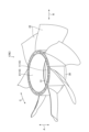
- FIG. 1 is a perspective view of an impeller according to a first embodiment.
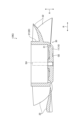
- FIG. 2 is a cross-sectional view of the impeller shown in FIG.
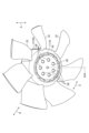
- FIG. 3 is a perspective view of the impeller shown in FIG. 1 as viewed from the front side.
- FIG. 4 is a cross-sectional view of a mold used when manufacturing the resin member of the impeller shown in FIG.
- FIG. 5 is a perspective view of a plurality of nozzles used when manufacturing the resin member of the impeller shown in FIG.
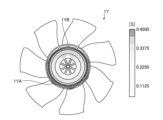
- FIG. 6 is a front view showing the time it takes for the molten resin to reach the impeller of the comparative example when the impeller is manufactured by molding.
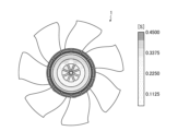
- FIG. 7 is a front view showing the time it takes for molten resin to reach the impeller shown in FIG.
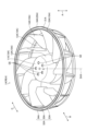
- FIG. 8 is a perspective view of an impeller according to the second embodiment.
- FIG. 9 is a partial cross-sectional view of a portion of the impeller shown in FIG.
- FIG. 10 is a cross-sectional view of a portion of a mold for manufacturing the impeller shown in FIG.
- FIG. 11 is a cross-sectional view of a portion of an impeller of a comparative example.
- FIG. 12 is a front view showing the time it takes for molten resin to reach the impeller of the comparative example when the impeller is manufactured by molding.
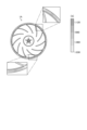
- FIG. 13 is a front view showing the time when molten resin reaches the impeller shown in FIG. 8 when the impeller is manufactured by molding.
- Fig. 1 is a perspective view of an impeller 1 according to a first embodiment.
- Fig. 2 is a cross-sectional view of the impeller 1 shown in Fig. 1.
- Fig. 3 is a perspective view of the impeller 1 shown in Fig. 1 as viewed from the front side.
- the direction in which the shaft SH described later extends is called the axial direction A
- the direction in which the shaft SH described later rotates is called the circumferential direction C
- the direction that is included in a plane perpendicular to the axial direction A, passes through the axis SHX of the shaft SH, and is perpendicular to the circumferential direction C is called the radial direction R.
- the impeller 1 shown in Figures 1 to 3 is used, for example, in a fan that is built into an electronic device and is used to cool components installed inside the device.
- a shaft SH is connected to the output shaft of a motor, and as the motor is driven, the shaft SH rotates together with the output shaft in the circumferential direction C, thereby blowing air onto the components.
- the impeller 1 comprises a shaft SH and a resin member RE.
- the shaft SH is a so-called rotating shaft, is made of metal, and is formed into a cylindrical shape extending along the axial direction A.
- the shaft SH has an axis SHX that extends along the axial direction A, and is arranged to be rotatable about the axis SHX.
- the resin member RE is cylindrical with a bottom.
- the resin member RE includes a first portion 10 including a gate mark GE, a second portion 20 not including a gate mark GE, and a connecting portion 30 that connects the first portion 10 and the second portion 20 and in which a recess 31 is formed.
- the first portion 10 is a top surface portion 11 that is perpendicular to the axial direction A along which the axis SHX of the shaft SH extends. More specifically, the top surface portion 11 is formed, for example, in the shape of a circular plate when viewed from the axial direction A.
- the top surface portion 11 according to this embodiment has multiple gate marks GE. More specifically, the top surface portion 11 has seven gate marks GE.
- the gate marks GE are arranged side by side near the attachment position of the shaft SH on the top surface portion 11. Furthermore, the gate marks GE are arranged around the axis SHX and spaced apart in the circumferential direction C.
- the second portion 20 is a wall portion 21 having a plurality of blades 22 and extending along the axial direction A. More specifically, the wall portion 21 is formed, for example, in a cylindrical shape. Furthermore, the wall portion 21 according to this embodiment is provided with seven blades 22.
- a recess 31 is disposed at a position where the second portion 20 is connected to the first portion 10 in a bent manner.
- the recess 31 is continuous in the circumferential direction C and goes around the circumference of the shaft SH.
- the recess 31 is also formed on the inner surface of the resin member RE.
- the recess 31 of the impeller 1 according to this embodiment is thinner than the top surface portion 11 and also thinner than the wall portion 21.
- Figure 4 is a cross-sectional view of a mold MO used when manufacturing the resin member RE of the impeller 1 shown in Figure 1.
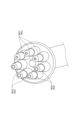
- Figure 5 is a perspective view of multiple nozzles NO used when manufacturing the resin member RE of the impeller 1 shown in Figure 1.
- a cavity CA is provided inside the mold MO.
- the shape of the cavity CA corresponds to the shape of the resin member RE.
- a columnar member MO1 of the same shape and size as the shaft SH is placed inside the mold MO.
- the multiple nozzles NO shown in FIG. 4 are used when injecting molten resin into the cavity CA from an opening MO2 provided in the mold MO.
- the multiple nozzles NO in this embodiment are, for example, seven, including three first nozzles NO1 and four second nozzles NO2.
- the worker When manufacturing the resin member RE by molding using the metal mold MO, the worker first places the tip of the nozzle NO into the opening MO2 of the metal mold MO, and then injects molten resin from each nozzle NO into the cavity CA.
- the molten resin spreads around the nozzle NO, and spreads to the part CA11 corresponding to the top surface part 11 (first part 10) of the cavity CA. Then, when the molten resin flows to the part CA31 corresponding to the recess 31 in the cavity CA, the resistance of the molten resin when it flows through the part CA31 corresponding to the recess 31 is large, so the molten resin hardly flows in the direction indicated by the arrow F1 in FIG. 4, and the molten resin flows along the radial direction R. In other words, the molten resin is blocked by the part CA31 with large fluid resistance.
- the part CA31 corresponding to the recess 31 in the cavity CA has the function of waiting for the timing when the pressure of the molten resin becomes high.
- the part CA31 corresponding to the recess 31 in the cavity CA has the function of adjusting the timing when the resin flows out beyond the part CA31.
- the molten resin flows to the portion CA21, which corresponds to the wall portion 21 (second portion 20) through the recess 31, so that the molten resin flows in the direction indicated by the arrow F1 around the entire circumference of the recess 31 in the radial direction R.
- the worker pours resin into all of the portion CA11 that corresponds to the wall portion 21, applies a holding pressure to the resin, and then stops injecting the molten resin into the cavity CA. The worker then cools the molten resin to produce the resin member RE, and then removes the resin member RE from the mold MO. Finally, the shaft SH is attached to the resin member RE, completing the manufacture of the impeller 1.
- FIG. 6 is a front view showing the time it takes for the molten resin to reach the impeller 1Y of the comparative example when it is manufactured by molding.
- Figure 7 is a front view showing the time it takes for the molten resin to reach the impeller 1 shown in Figure 1 when it is manufactured by molding. Note that in Figures 6 and 7, the times shown on the right side of the figures indicate the time [seconds] from when the molten resin is injected from nozzle NO until the molten resin reaches each part.
- the impeller 1Y of the comparative example has the same shape as the impeller 1 of this embodiment, except that it does not have a recess 31.
- the diameter of each gate diameter of the first nozzle NO1 is, for example, 0.8 mm.
- the diameter of each gate diameter of the second nozzle NO2 is, for example, 1.6 mm.
- the impeller 1 according to this embodiment shown in FIG. 7 0.45 seconds after the molten resin is injected from the nozzle NO, the molten resin has exceeded the recesses 31 all around in the radial direction R, and there is no bias in the areas where the resin is present. In other words, in the impeller 1 according to this embodiment, the resin filled into the mold MO is uniform.
- the impeller 1 according to this embodiment is formed of a resin member RE with a metal shaft SH attached.
- the resin member RE includes a first portion 10 including a gate mark GE, a second portion 20 not including a gate mark GE, and a connecting portion 30 connecting the first portion 10 and the second portion 20 and in which a recess 31 is formed. Therefore, when manufacturing the impeller 1 according to this embodiment, the recess 31 allows the resin to be filled into each portion of the cavity CA so that the molten resin is uniform. Therefore, the impeller 1 according to this embodiment can prevent the center of gravity of the impeller 1 from shifting from the center of rotation with respect to the axis SHX of the shaft SH when the blades 22 are rotated in the circumferential direction C.
- the first portion 10 is a top surface portion 11 that is perpendicular to the axial direction A along which the axis SHX of the shaft SH extends
- the second portion 20 is a wall portion 21 that is provided with a plurality of blades 22 and extends along the axial direction A, and a recess 31 is disposed at a position where the second portion 20 is connected to the first portion 10 so as to bend.
- the resin member RE is cylindrical with a bottom, and a recess 31 is formed on the inner surface of the resin member RE.
- the recess 31 is provided radially outward of the gate mark GE.
- the gate marks GE are arranged side by side near the attachment position of the shaft SH on the top surface portion 11.
- the impeller 1 is described as being manufactured by separately manufacturing the shaft SH and the resin member RE, and then attaching the shaft SH to the resin member RE.
- the impeller 1 of this embodiment is not limited to this.
- the impeller 1 of this embodiment may be manufactured by insert molding by fixing a pre-manufactured shaft SH to a mold MO instead of the columnar member MO1, and then injecting molten resin into the cavity CA of the mold MO.
- the impeller 1 according to the embodiment described above is formed using multiple nozzles NO with different gate diameters.
- the impeller 1 according to this embodiment is not limited to this.
- the impeller 1 may be formed using multiple nozzles NO with the same gate diameter.
- FIG. 8 is a perspective view of the impeller 1A according to the second embodiment.
- Figure 9 is a partial cross-sectional view of a part of the impeller 1A shown in Figure 8.
- Figure 10 is a cross-sectional view of a part of a mold MOA for manufacturing the impeller 1A shown in Figure 8. Note that in the configuration of the impeller 1A according to the second embodiment, the same components as those of the impeller 1 according to the first embodiment are denoted by the same reference numerals and description thereof will be omitted.
- the impeller 1A includes a shaft SH (not shown) and a resin member REA.
- the resin member REA includes a first portion 10A including a gate mark GE, a second portion 20A not including a gate mark GE, and a connecting portion 30A that connects the first portion 10A and the second portion 20A and in which a recess 31A is formed.
- the resin member REA includes a bottom surface portion 11A, a wall portion 12A, a top surface portion 13A, a plurality of blades 14A, and an annular portion 32A.
- the bottom surface portion 11A has multiple gate marks GE and is perpendicular to the axial direction A along which the axis SHX of the shaft SH extends. More specifically, when viewed from the axial direction A, for example, the bottom surface portion 11A is formed in the shape of a circular plate and is perpendicular to the axial direction A.
- the wall portion 12A is connected to the bottom surface portion 11A. More specifically, the wall portion 12A is formed, for example, in a cylindrical shape extending in the axial direction A.
- Top surface portion 13A is connected to wall portion 12A and is perpendicular to axial direction A. More specifically, top surface portion 13A is formed, for example, in the shape of a circular plate when viewed from axial direction A.
- the multiple blades 14A are connected to the top surface portion 13A and extend in the axial direction A.
- the resin member REA in this embodiment has, for example, 11 blades 14A.
- the annular portion 32A connects the tips of the multiple blades 14A in the circumferential direction C.
- the annular portion 32A is continuous in the circumferential direction C and goes around the shaft SH (not shown).
- the annular portion 32A has an inner annular portion 33A located on the inside in the radial direction R, an outer annular portion 34A located on the outside in the radial direction R, and a connecting portion 30A that connects the inner annular portion 33A and the outer annular portion 34A.
- the annular portion 32A forms a recess 31A by the inner annular portion 33A, the outer annular portion 34A, and the connecting portion 30A.
- the thickness t33 of the inner annular portion 33A is, for example, 0.5 mm
- the thickness t34 of the outer annular portion 34A is, for example, 0.5 mm
- the thickness t30 of the connecting portion 30A is, for example, 0.5 mm.
- the first part 10A is made up of a bottom surface portion 11A, a wall portion 12A, a top surface portion 13A, a blade 14A, and an inner annular portion 33A.
- the second portion 20A is the outer annular portion 34A.
- the annular portion 32A forms a recess 31A with the inner annular portion 33A, the outer annular portion 34A, and the connecting portion 30A.
- the recess 31A is continuous in the circumferential direction C and goes around the shaft SH.
- the recess 31A is also formed on the inner surface of the resin member REA.
- the resin member REA of this embodiment is formed by injecting molten resin into a mold MOA having a cavity CAA that corresponds to the shape of the impeller 1A, similar to the impeller 1 of the first embodiment.
- the molten resin spreads around the nozzle NO, and then to the part of the cavity CAA that corresponds to the bottom surface 11A, the part that corresponds to the wall 12A, the part that corresponds to the top surface 13A, and the part that corresponds to the vanes 14A, for example in that order.
- portion 33CA which corresponds to inner annular portion 33A in cavity CAA
- the molten resin is blocked by portion 30CA, which has high fluid resistance.
- portion 30CA in cavity CAA has the function of waiting for the timing when the pressure of the molten resin becomes high.
- portion 30CA in cavity CAA, which corresponds to connecting portion 30A has the function of adjusting the timing when the resin flows out beyond portion 30CA.
- the molten resin flows to the portion 30CA corresponding to the connecting portion 30A in the cavity CAA and the portion 34CA corresponding to the outer annular portion 34A in the cavity CAA. Therefore, after the molten resin flows in the direction indicated by the arrow F1 around the entire circumference of the portion 30CA in the radial direction R, the resin flows into the portion 34CA corresponding to the outer annular portion 34A.
- the worker pours resin into all of the portion 34CA that corresponds to the outer annular portion 34A, applies a holding pressure to the resin, and then stops injecting the molten resin into the cavity CAA. The worker then cools the molten resin to produce the resin member REA, and then removes the resin member REA from the mold MOA. Finally, the shaft SH is attached to the resin member REA, completing the manufacture of the impeller 1A.
- Figure 11 is a cross-sectional view of a portion of the impeller 1Z of the comparative example.
- Figure 12 is a front view showing the time it takes for the molten resin to reach the impeller 1Z of the comparative example when it is manufactured by molding.
- Figure 13 is a front view showing the time it takes for the molten resin to reach the impeller 1A shown in Figure 8 when it is manufactured by molding. Note that the times shown on the right side of Figures 12 and 13 indicate the time [seconds] from when the molten resin is injected from nozzle NO until the molten resin reaches each part.
- the thickness t33Z of the inner annular portion 33Z is, for example, 0.85 mm
- the thickness t34Z of the outer annular portion 34Z is, for example, 0.85 mm
- the thickness t30Z of the connecting portion 30Z is, for example, 1.52 mm.
- the depth of the recess 31Z of the impeller 1Z of the comparative example is shallower than the depth of the recess 31A of the impeller 1A of the present embodiment, but is otherwise the same shape as the impeller 1A of the present embodiment.
- the impeller 1A according to this embodiment is an impeller 1A to which a metal shaft SH is attached and which is formed of a resin member REA.
- the resin member REA includes a first portion 10A including a gate mark GE, a second portion 20A not including a gate mark GE, and a connecting portion 30A connecting the first portion 10A and the second portion 20A and forming a recess 31A. Therefore, when manufacturing the impeller 1A according to this embodiment, the recess 31A allows the resin to be filled into each portion of the cavity CAA so that the molten resin is uniform. Therefore, the impeller 1A according to this embodiment can prevent the center of gravity of the impeller 1A from shifting from the center of rotation with respect to the axis SHX of the shaft SH when the blades 14A are rotated in the circumferential direction C.
- the resin member REA has a gate mark GE and includes a bottom surface portion 11A perpendicular to the axial direction A along which the axis SHX of the shaft SH extends, a wall portion 12A connected to the bottom surface portion 11A, a top surface portion 13A connected to the wall portion 12A and perpendicular to the axial direction A, a plurality of blades 14A connected to the top surface portion 13A and extending in the axial direction A, and an annular portion 32A connecting the tips of the plurality of blades 14A in the circumferential direction C.
- the annular portion 32A has an inner annular portion 33A located on the inside in the radial direction R, an outer annular portion 34A located on the outside in the radial direction R, and a connecting portion 30A connecting the inner annular portion 33A and the outer annular portion 34A.
- the first portion 10A includes the bottom surface portion 11A, the wall portion 12A, the top surface portion 13A, the blades 14A, and the inner annular portion 33A.
- the second portion 20A is the outer annular portion 34A.
- the annular portion 32A forms a recess 31A with the inner annular portion 33A, the outer annular portion 34A, and the connecting portion 30A.
Landscapes
- Engineering & Computer Science (AREA)
- Mechanical Engineering (AREA)
- Manufacturing & Machinery (AREA)
- General Engineering & Computer Science (AREA)
- Structures Of Non-Positive Displacement Pumps (AREA)
- Moulds For Moulding Plastics Or The Like (AREA)
- Injection Moulding Of Plastics Or The Like (AREA)
Abstract
インペラ(1)は、金属製のシャフト(SH)が取り付けられ、樹脂部材(RE)で形成される。前記樹脂部材(RE)は、前記ゲート痕(GE)を含む第1部分(10)と、前記ゲート痕(GE)を含まない第2部分(20)と、前記第1部分(10)と前記第2部分(20)との間を連結し、凹部(31)を形成する連結部(30)と、を備える。
Description
本発明は、インペラに関する。
シャフトを埋込金具とし、溶融した樹脂をキャビティに流してインペラを製造することが知られている(例えば、特許文献1参照)。
しかしながら、従来の製造法では、キャビティに樹脂を均一に充填できない場合があり、重心が回転中心からずれる可能性がある。
本発明は、上記に鑑みてなされたものであって、重心が回転中心からずれることを抑制することができるインペラを提供することにある。
上述した課題を解決し、目的を達成するために、本発明に係るインペラは、金属製のシャフトが取り付けられ、樹脂部材で形成され、前記樹脂部材は、前記ゲート痕を含む第1部分と、前記ゲート痕を含まない第2部分と、前記第1部分と前記第2部分との間を連結し、凹部を形成する連結部と、を備える。
本発明に係るインペラの一態様によれば、重心が回転中心からずれることを抑制することができるインペラを提供することができる。
以下に、実施形態に係るインペラを図面に基づいて詳細に説明する。なお、図面における各要素の寸法の関係、各要素の比率などは、現実と異なる場合がある。図面の相互間においても、互いの寸法の関係や比率が異なる部分が含まれている場合がある。
[第1実施形態]
図1は、第1実施形態に係るインペラ1の斜視図である。図2は、図1に示すインペラ1の断面図である。図3は、図1に示すインペラ1を正面側から視た斜視図である。
図1は、第1実施形態に係るインペラ1の斜視図である。図2は、図1に示すインペラ1の断面図である。図3は、図1に示すインペラ1を正面側から視た斜視図である。
第1実施形態に係る図1に示すインペラ1の説明において、方向の理解を容易にするため、後述するシャフトSHが延びる方向を軸方向Aと呼び、後述するシャフトSHが回動する方向を周方向Cと呼び、軸方向Aに対して直交する平面に含まれ、かつ、シャフトSHの軸芯SHXを通過し、周方向Cに対して直交する方向を径方向Rと呼ぶ。
図1~図3に示すインペラ1は、例えば、電子機器に内蔵され、機器の内部に設けられた部品の冷却等に用いられるファンに使用される。このようなインペラ1は、例えば、モータの出力軸にシャフトSHが連結され、モータの駆動に伴って出力軸と共にシャフトSHが周方向Cへ回転することによって、風が部品に送風される。
インペラ1は、シャフトSHと、樹脂部材REと、を備える。シャフトSHは、いわゆる回転軸であって、金属製であり、軸方向Aに沿って延びる円柱状に形成される。シャフトSHは、軸方向Aに沿って延在する軸芯SHXを有し、かつ、軸芯SHXを中心に回転可能に設けられる。
樹脂部材REは、有底円筒状である。樹脂部材REは、ゲート痕GEを含む第1部分10と、ゲート痕GEを含まない第2部分20と、第1部分10と第2部分20との間を連結し、凹部31が形成される連結部30と、を備える。
第1部分10は、シャフトSHの軸芯SHXが延在する軸方向Aに対して直交する天面部11である。より具体的に説明すると、天面部11は、例えば、軸方向Aから視た場合、円形の板状に形成される。本実施形態に係る天面部11は、複数のゲート痕GEを有する。より具体的に説明すると、天面部11は、7つのゲート痕GEを有する。ゲート痕GEは、天面部11のシャフトSHの取り付け位置の近傍に並んで配置される。さらに、ゲート痕GEは、軸芯SHXの周囲に配置され、かつ、周方向Cにおいて間隔をあけて配置される。
第2部分20は、複数の羽根22が設けられ、軸方向Aに沿って延びる壁部21である。より具体的に説明すると、壁部21は、例えば、円筒状に形成される。また、本実施形態に係る壁部21には、7枚の羽根22が設けられる。
連結部30において、第1部分10に対して第2部分20が折れ曲がるように繋がる位置に凹部31が配置される。凹部31は、周方向Cにおいて連続し、シャフトSHの周囲を一周する。また、凹部31は、樹脂部材REの内側面に形成される。さらに、本実施形態に係るインペラ1の凹部31は、天面部11よりも肉薄であり、かつ、壁部21よりも肉薄である。
次に、樹脂部材REの製造方法について、図4、図5を用いて説明する。図4は、図1に示すインペラ1が有する樹脂部材REを製造する際に使用する金型MOの断面図である。図5は、図1に示すインペラ1が有する樹脂部材REを製造する際に使用する複数のノズルNOの斜視図である。金型MOの内部には、図4に示すように、キャビティCAが設けられる。キャビティCAの形状は、樹脂部材REの形状に対応する。また、金型MOの内部には、シャフトSHと同形同大の柱状部材MO1が配置される。
図4に示す複数のノズルNOは、金型MOに設けられた開口MO2から、溶融した樹脂をキャビティCAに注入する際に使用される。本実施形態に係る複数のノズルNOは、例えば、7本であり、3本の第1ノズルNO1と4本の第2ノズルNO2とが含まれる。
そして、金型MOを用いたモールド成型によって樹脂部材REを製造する際、先ず、作業者は、ノズルNOの先端を金型MOの開口MO2に配置した後、それぞれのノズルNOから溶融した樹脂をキャビティCAに注入する。
その際、溶融した樹脂は、ノズルNOを中心に、ノズルNOの周囲に広がり、キャビティCAにおける天面部11(第1部分10)に相当する部分CA11に広がる。そして、キャビティCAにおける凹部31に相当する部分CA31まで溶融した樹脂が流れると、凹部31に相当する部分CA31を溶融した樹脂が流れる際の抵抗が大きいため、図4中、矢印F1で示す方向に溶融した樹脂はほとんど流れず、径方向Rに沿って溶融した樹脂が流れることとなる。つまり、流体抵抗が大きい部分CA31によって、溶融した樹脂が堰き止められる。また、言い方を変えると、キャビティCAにおける凹部31に相当する部分CA31は、溶融した樹脂の圧力が高くなるタイミングを待つ機能を有する。別言すると、キャビティCAにおける凹部31に相当する部分CA31は、当該部分CA31を超えて樹脂が流れ出すタイミングを調整する機能を有する。
その後、キャビティCAにおける天面部11に相当する部分CA11のすべてに樹脂が流れ込むと、溶融した樹脂が流れる先は、凹部31を介した壁部21(第2部分20)に相当する部分CA21であるため、凹部31における径方向Rの全周において、溶融した樹脂が矢印F1で示す方向へ流れることになる。
その後、作業者は、壁部21に相当する部分CA11のすべてに樹脂を流し込み、樹脂に保圧を加えた後、キャビティCAに、溶融した樹脂を注入することを停止する。その後、作業者は、溶融した樹脂を冷却して樹脂部材REを製造した後、金型MOから樹脂部材REを取り出す。最後に、樹脂部材REにシャフトSHを取り付けることで、インペラ1の製造を終了する。
次に、図6、図7を用いて、比較例のインペラ1Yと、本実施形態に係るインペラ1について説明する。図6は、比較例のインペラ1Yを、モールド成型によって製造した際において、溶融した樹脂が到達した時間を示す正面図である。図7は、図1に示すインペラ1を、モールド成型によって製造した際において、溶融した樹脂が到達した時間を示す正面図である。なお、図6および図7において、図中、右側に示す時間は、ノズルNOから溶融した樹脂を注入した時から、溶融した樹脂が各部に到達するまでの時間[秒]を示してある。比較例のインペラ1Yは、凹部31を有していない点を除いて、本実施形態に係るインペラ1と同一形状である。
図6に示す比較例のインペラ1Yでは、ノズルNOから溶融した樹脂を注入した時から、0.45[秒]経過した時点において、溶融した樹脂が、凹部31に相当する箇所を超えた箇所1YAと、凹部31に相当する箇所を超えていない箇所1YBとがあり、溶融した樹脂が存在する部分に偏りが発生していた。つまり、比較例のインペラ1Yでは、金型MOに充填する樹脂が不均一となっていた。
この比較の際、本実施形態に係るインペラ1を製造するノズルNOにおいて、第1ノズルNO1のそれぞれのゲート径の直径は、例えば0.8mmである。一方、第2ノズルNO2のそれぞれのゲート径の直径は、例えば1.6mmである。つまり、キャビティCAに充填する樹脂が不均一となるおそれがある状態で、インペラ1を製造した。
図7に示す本実施形態に係るインペラ1では、ノズルNOから溶融した樹脂を注入した時から、0.45[秒]経過した時点において、径方向Rの全周において、溶融した樹脂が、凹部31を超えており、樹脂が存在する部分に偏りが発生していない。つまり、本実施形態に係るインペラ1では、金型MOに充填する樹脂が均一となっていた。
以上に説明したように、本実施形態に係るインペラ1は、金属製のシャフトSHが取り付けられ、樹脂部材REで形成される。樹脂部材REは、ゲート痕GEを含む第1部分10と、ゲート痕GEを含まない第2部分20と、第1部分10と第2部分20との間を連結し、凹部31が形成される連結部30と、を備える。そのため、本実施形態に係るインペラ1を製造する際、凹部31によって、溶融した樹脂が均一となるように、キャビティCAの各部に樹脂を充填することができる。そのため、本実施形態に係るインペラ1は、羽根22を周方向Cへ回転させた際、シャフトSHの軸芯SHXに対してインペラ1の重心が回転中心からずれることを抑制することができる。
本実施形態に係るインペラ1は、第1部分10は、シャフトSHの軸芯SHXが延在する軸方向Aに対して直交する天面部11であり、第2部分20は、複数の羽根22が設けられ、軸方向Aに沿って延びる壁部21であり、第1部分10に対して第2部分20が折れ曲がるように繋がる位置に凹部31が配置される。
本実施形態に係るインペラ1において、樹脂部材REは、有底円筒状であり、樹脂部材REの内側面に凹部31が形成される。
本実施形態に係るインペラ1において、凹部31は、ゲート痕GEよりも径方向Rの外側に設けられる。
本実施形態に係るインペラ1において、ゲート痕GEは、天面部11のシャフトSHの取り付け位置の近傍に並んで配置される。
なお、上述した実施形態に係るインペラ1は、シャフトSHと、樹脂部材REと、を別々に製造した後、樹脂部材REにシャフトSHを取り付けるものを説明した。しかし、本実施形態に係るインペラ1は、それに限られない。例えば、本実施形態に係るインペラ1は、柱状部材MO1の代わりに、予め製造したシャフトSHを金型MOに固定した後、金型MOのキャビティCAに溶融した樹脂を注入することによりインサート成型で製造してもよい。
また、上述した実施形態に係るインペラ1は、ゲート径が異なる複数のノズルNOを使用して形成するものを説明した。しかし、本実施形態に係るインペラ1は、それに限られない。例えば、インペラ1は、同一のゲート径の複数のノズルNOを使用して形成してもよい。
[第2実施形態]
次に、第2実施形態に係るインペラ1Aに関して図8、図9、図10を用いて説明する。図8は、第2実施形態に係るインペラ1Aの斜視図である。図9は、図8に示すインペラ1Aの一部における部分断面図である。図10は、図8に示すインペラ1Aを製造する金型MOAの一部の断面図である。なお、第2実施形態に係るインペラ1Aの構成において、第1実施形態に係るインペラ1と同一の構成については、同一の符号を付して説明を省略する。
次に、第2実施形態に係るインペラ1Aに関して図8、図9、図10を用いて説明する。図8は、第2実施形態に係るインペラ1Aの斜視図である。図9は、図8に示すインペラ1Aの一部における部分断面図である。図10は、図8に示すインペラ1Aを製造する金型MOAの一部の断面図である。なお、第2実施形態に係るインペラ1Aの構成において、第1実施形態に係るインペラ1と同一の構成については、同一の符号を付して説明を省略する。
インペラ1Aは、不図示のシャフトSHと、樹脂部材REAと、を備える。樹脂部材REAは、ゲート痕GEを含む第1部分10Aと、ゲート痕GEを含まない第2部分20Aと、第1部分10Aと第2部分20Aとの間を連結し、凹部31Aが形成される連結部30Aと、を備える。
また、本実施形態に係るインペラ1Aにおいて、樹脂部材REAは、底面部11Aと、壁部12Aと、天面部13Aと、複数の羽根14Aと、環状部32Aと、を備える。
底面部11Aは、複数のゲート痕GEを有し、シャフトSHの軸芯SHXが延在する軸方向Aに対して直交する。より具体的に説明すると、底面部11Aは、例えば軸方向Aから視た場合、円形の板状に形成され、軸方向Aと直交する。
壁部12Aは、底面部11Aに繋がる。より具体的に説明すると、壁部12Aは、例えば軸方向Aに延在する円筒状に形成される。
天面部13Aは、壁部12Aに繋がり、軸方向Aに対して直交する。より具体的に説明すると、天面部13Aは、例えば、軸方向Aから視た場合、円形の板状に形成される。
複数の羽根14Aは、天面部13Aに繋がり、軸方向Aに延在する。本実施形態に係る樹脂部材REAは、例えば11枚の羽根14Aを有する。
環状部32Aは、複数の羽根14Aの先端部を周方向Cで繋げる。本実施形態に係る環状部32Aは、周方向Cにおいて連続し、不図示のシャフトSHの周囲を一周する。
環状部32Aは、径方向Rの内側に位置する内部環状部33Aと、径方向Rの外側に位置する外部環状部34Aと、内部環状部33Aと外部環状部34Aとを連結する連結部30Aとを有する。環状部32Aは、内部環状部33Aと外部環状部34Aと連結部30Aにより凹部31Aを形成する。
内部環状部33Aの厚さt33は、例えば0.5mmであり、外部環状部34Aの厚さt34は、例えば0.5mmであり、連結部30Aの厚さt30は、例えば0.5mmである。
第1部分10Aは、底面部11A、壁部12A、天面部13A、羽根14A、および、内部環状部33Aである。
第2部分20Aは、外部環状部34Aである。そして、環状部32Aは、内部環状部33Aと外部環状部34Aと連結部30Aにより凹部31Aを形成する。凹部31Aは、周方向Cにおいて連続し、シャフトSHの周囲を一周する。また、凹部31Aは、樹脂部材REAの内側面に形成される。
本実施形態に係る樹脂部材REAは、第1実施形態に係るインペラ1と同様、インペラ1Aの形状に対応するキャビティCAAを有する金型MOAに溶融した樹脂を注入することによって形成される。
その際、溶融した樹脂は、ノズルNOを中心に、ノズルNOの周囲に広がり、キャビティCAAにおける底面部11Aに相当する部分、壁部12Aに相当する部分、天面部13Aに相当する部分、および、羽根14Aに相当する部分に、例えばこの順番で広がる。
そして、キャビティCAAにおける内部環状部33Aに相当する部分33CAまで溶融した樹脂が流れると、凹部31Aにおける連結部30Aに相当する部分30CAを溶融した樹脂が流れる際の抵抗が大きいため、図10中、矢印F1Aで示す方向に溶融した樹脂はほとんど流れず、部分33CAにおいて、径方向Rに沿って溶融した樹脂が流れることとなる。つまり、流体抵抗が大きい部分30CAによって、溶融した樹脂が堰き止められる。また、言い方を変えると、キャビティCAAにおける部分30CAは、溶融した樹脂の圧力が高くなるタイミングを待つ機能を有する。別言すると、キャビティCAAにおける連結部30Aに相当する部分30CAは、当該部分30CAを超えて樹脂が流れ出すタイミングを調整する機能を有する。
その後、キャビティCAAにおける内部環状部33Aに相当する部分33CAのすべてに樹脂が流れ込むと、溶融した樹脂が流れる先は、キャビティCAAにおける連結部30Aに相当する部分30CA、および、キャビティCAAにおける外部環状部34Aに相当する部分34CAであるため、部分30CAにおける径方向Rの全周において、溶融した樹脂が矢印F1で示す方向へ流れた後、外部環状部34Aに相当する部分34CAに樹脂が流れることになる。
その後、作業者は、外部環状部34Aに相当する部分34CAのすべてに樹脂を流し込み、樹脂に保圧を加えた後、キャビティCAAに、溶融した樹脂を注入することを停止する。その後、作業者は、溶融した樹脂を冷却して樹脂部材REAを製造した後、金型MOAから樹脂部材REAを取り出す。最後に、樹脂部材REAにシャフトSHを取り付けることで、インペラ1Aの製造を終了する。
次に、図11、図12、図13を用いて、比較例のインペラ1Zと、本実施形態に係るインペラ1Aについて説明する。図11は、比較例のインペラ1Zの一部の断面図である。図12は、比較例のインペラ1Zを、モールド成型によって製造する際において、溶融した樹脂が到達した時間を示す正面図である。図13は、図8に示すインペラ1Aを、モールド成型によって製造する際において、溶融した樹脂が到達した時間を示す正面図である。なお、図12および図13において、図中、右側に示す時間は、ノズルNOから溶融した樹脂を注入した時から、溶融した樹脂が各部に到達するまでの時間[秒]を示してある。
比較例のインペラ1Zにおいて、内部環状部33Zの厚さt33Zは、例えば0.85mmであり、外部環状部34Zの厚さt34Zは、例えば0.85mmであり、連結部30Zの厚さt30Zは、例えば1.52mmである。つまり、比較例のインペラ1Zの凹部31Zの深さは、本実施形態に係るインペラ1Aの凹部31Aの深さよりも浅い点を除いて、本実施形態に係るインペラ1Aと同一形状である。
図12に示す比較例のインペラ1Zでは、ノズルNOから溶融した樹脂を注入した時から、1.120[秒]経過した時点において、外部環状部34Aの一部に溶融した樹脂が注入されているものの、まだ溶融した樹脂が注入されていない箇所1ZAが存在していた。つまり、比較例のインペラ1Zでは、金型MOAに充填する樹脂が不均一となっていた。
一方、図13に示す本実施形態に係るインペラ1Aでは、ノズルNOから溶融した樹脂を注入した時から、1.12[秒]経過した時点において、径方向Rの全周において、溶融した樹脂が、外部環状部34Aの全ての部分に溶融した樹脂が注入された。つまり、本実施形態に係るインペラ1Aでは、金型MOAに充填する樹脂が均一となっていた。
以上に説明したように、本実施形態に係るインペラ1Aは、金属製のシャフトSHが取り付けられ、樹脂部材REAで形成されるインペラ1Aであって、樹脂部材REAは、ゲート痕GEを含む第1部分10Aと、ゲート痕GEを含まない第2部分20Aと、第1部分10Aと第2部分20Aとの間を連結し、凹部31Aが形成される連結部30Aと、を備える。そのため、本実施形態に係るインペラ1Aを製造する際、凹部31Aによって、溶融した樹脂が均一となるように、キャビティCAAの各部に樹脂を充填することができる。そのため、本実施形態に係るインペラ1Aは、羽根14Aを周方向Cへ回転させた際、シャフトSHの軸芯SHXに対してインペラ1Aの重心が回転中心からずれることを抑制することができる。
本実施形態に係るインペラ1Aにおいて、樹脂部材REAは、ゲート痕GEを有し、シャフトSHの軸芯SHXが延在する軸方向Aに対して直交する底面部11Aと、底面部11Aに繋がる壁部12Aと、壁部12Aに繋がり、軸方向Aに対して直交する天面部13Aと、天面部13Aに繋がり、軸方向Aに延在する複数の羽根14Aと、複数の羽根14Aの先端部を周方向Cで繋げる環状部32Aと、を備える。環状部32Aは、径方向Rの内側に位置する内部環状部33Aと、径方向Rの外側に位置する外部環状部34Aと、内部環状部33Aと外部環状部34Aとを連結する連結部30Aとを有する。第1部分10Aは、底面部11A、壁部12A、天面部13A、羽根14A、および、内部環状部33Aである。第2部分20Aは、外部環状部34Aである。環状部32Aは、内部環状部33Aと外部環状部34Aと連結部30Aにより凹部31Aを形成する。
以上、本発明に係るインペラ1、1Aの実施形態に基づいて説明したが、本発明は実施形態に限定されるものではなく、本発明の要旨を逸脱しない範囲での種々の変更が可能であることも言うまでもない。上述した各実施形態の構成要素を適宜組み合わせて構成したものも本発明に含まれる。そのような要旨を逸脱しない範囲での種々の変更を行ったものも本発明の技術的範囲に含まれるものであり、そのことは、当業者にとって請求の範囲の記載から明らかである。
1、1A インペラ、 10、10A 第1部分、 11、13A 天面部、 11A 底面部、 12A 壁部、 20、20A 第2部分、 21 壁部、 22 羽根、 30、30A 連結部、 31、31A 凹部、 32A 環状部、 33A 内部環状部、 34A 外部環状部、 C 周方向、 GE ゲート痕、 R 径方向、 RE、REA 樹脂部材、 SH シャフト、 SHX 軸芯
Claims (6)
- 金属製のシャフトが取り付けられ、樹脂部材で形成され、
前記樹脂部材は、
ゲート痕を含む第1部分と、
前記ゲート痕を含まない第2部分と、
前記第1部分と前記第2部分との間を連結し、凹部が形成される連結部と、
を備える、
インペラ。 - 前記第1部分は、前記シャフトの軸芯が延在する軸方向に対して直交する天面部であり、
前記第2部分は、複数の羽根が設けられ、前記軸方向に沿って延びる壁部であり、
前記第1部分に対して前記第2部分が折れ曲がるように繋がる位置に前記凹部が配置される、
請求項1に記載のインペラ。 - 前記樹脂部材は、有底円筒状であり、
前記樹脂部材の内側面に前記凹部が形成される、
請求項2に記載のインペラ。 - 前記凹部は、前記ゲート痕よりも径方向外側に設けられる、
請求項2または3に記載のインペラ。 - 前記ゲート痕は、前記天面部の前記シャフトの取り付け位置の近傍に並んで配置される、
請求項4に記載のインペラ。 - 前記樹脂部材は、
前記ゲート痕を有し、前記シャフトの軸芯が延在する軸方向に対して直交する底面部と、
前記底面部に繋がる壁部と、
前記壁部に繋がり、前記軸方向に対して直交する天面部と、
前記天面部に繋がり、前記軸方向に延在する複数の羽根と、
前記複数の羽根の先端部を周方向で繋げる環状部と、
を備え、
前記環状部は、径方向の内側に位置する内部環状部と、前記径方向の外側に位置する外部環状部と、前記内部環状部と前記外部環状部とを連結する連結部とを有し、
前記第1部分は、前記底面部、前記壁部、前記天面部、前記羽根、および、前記内部環状部であり、
前記第2部分は、前記外部環状部であり、
前記環状部は、前記内部環状部と前記外部環状部と前記連結部により前記凹部を形成する、
請求項1に記載のインペラ。
Priority Applications (1)
| Application Number | Priority Date | Filing Date | Title |
|---|---|---|---|
| CN202480032924.1A CN121127351A (zh) | 2023-06-26 | 2024-04-23 | 叶轮 |
Applications Claiming Priority (2)
| Application Number | Priority Date | Filing Date | Title |
|---|---|---|---|
| JP2023-104114 | 2023-06-26 | ||
| JP2023104114A JP2025004428A (ja) | 2023-06-26 | 2023-06-26 | インペラ |
Publications (1)
| Publication Number | Publication Date |
|---|---|
| WO2025004510A1 true WO2025004510A1 (ja) | 2025-01-02 |
Family
ID=93938269
Family Applications (1)
| Application Number | Title | Priority Date | Filing Date |
|---|---|---|---|
| PCT/JP2024/015818 Ceased WO2025004510A1 (ja) | 2023-06-26 | 2024-04-23 | インペラ |
Country Status (3)
| Country | Link |
|---|---|
| JP (1) | JP2025004428A (ja) |
| CN (1) | CN121127351A (ja) |
| WO (1) | WO2025004510A1 (ja) |
Citations (5)
| Publication number | Priority date | Publication date | Assignee | Title |
|---|---|---|---|---|
| JP2010025087A (ja) * | 2008-07-24 | 2010-02-04 | Nippon Densan Corp | 軸流ファン |
| JP2012021485A (ja) * | 2010-07-15 | 2012-02-02 | Fujitsu General Ltd | プロペラファンおよびその製造方法 |
| JP2019181871A (ja) * | 2018-04-16 | 2019-10-24 | 株式会社エンプラス | 圧入嵌合部の空気逃がし構造 |
| JP2023032785A (ja) * | 2021-08-27 | 2023-03-09 | 日本電産サーボ株式会社 | インペラカップ及びファン |
| JP2023135910A (ja) * | 2022-03-16 | 2023-09-29 | ニデックアドバンスドモータ株式会社 | 軸流ファンのインペラおよび軸流ファン |
-
2023
- 2023-06-26 JP JP2023104114A patent/JP2025004428A/ja active Pending
-
2024
- 2024-04-23 CN CN202480032924.1A patent/CN121127351A/zh active Pending
- 2024-04-23 WO PCT/JP2024/015818 patent/WO2025004510A1/ja not_active Ceased
Patent Citations (5)
| Publication number | Priority date | Publication date | Assignee | Title |
|---|---|---|---|---|
| JP2010025087A (ja) * | 2008-07-24 | 2010-02-04 | Nippon Densan Corp | 軸流ファン |
| JP2012021485A (ja) * | 2010-07-15 | 2012-02-02 | Fujitsu General Ltd | プロペラファンおよびその製造方法 |
| JP2019181871A (ja) * | 2018-04-16 | 2019-10-24 | 株式会社エンプラス | 圧入嵌合部の空気逃がし構造 |
| JP2023032785A (ja) * | 2021-08-27 | 2023-03-09 | 日本電産サーボ株式会社 | インペラカップ及びファン |
| JP2023135910A (ja) * | 2022-03-16 | 2023-09-29 | ニデックアドバンスドモータ株式会社 | 軸流ファンのインペラおよび軸流ファン |
Also Published As
| Publication number | Publication date |
|---|---|
| CN121127351A (zh) | 2025-12-12 |
| JP2025004428A (ja) | 2025-01-15 |
Similar Documents
| Publication | Publication Date | Title |
|---|---|---|
| JP5454400B2 (ja) | プロペラファンおよびその製造方法 | |
| JP6463867B1 (ja) | 回転型動力伝達部材の製造方法 | |
| US20110027075A1 (en) | Ventilation fan | |
| US20080118357A1 (en) | Turbofan and manufacturing method thereof | |
| CN101479505A (zh) | 螺旋齿轮 | |
| CN102490307A (zh) | 具有改进的风扇环熔合线强度的塑料风扇 | |
| GB2197616A (en) | Method for the manufacture of a pump rotor | |
| JP3995010B2 (ja) | 多翼送風機の羽根車及びその製造方法 | |
| JP6026000B2 (ja) | 電動機の回転子、電動機、及び空気調和機 | |
| JP4846631B2 (ja) | 樹脂製ヘリカル歯車の成形金型及びこの成形金型を用いて成形された樹脂製ヘリカル歯車 | |
| WO2025004510A1 (ja) | インペラ | |
| JP4854692B2 (ja) | 射出成形樹脂フェースギヤ | |
| JP4993725B2 (ja) | 回転伝達手段及び回転伝達手段の射出成形金型 | |
| WO2016143372A1 (ja) | インペラの製造方法 | |
| CN108291556A (zh) | 离心泵及其径向叶轮 | |
| US10693354B2 (en) | Method for manufacturing impeller rotor assembly | |
| JP7801919B2 (ja) | 軸流ファンのインペラおよび軸流ファン | |
| US6506024B1 (en) | Inducer wheel and method of forming the same | |
| JP6379644B2 (ja) | モータ | |
| JP2005140095A (ja) | 遠心ファン | |
| CN115605687A (zh) | 具有结合线强度改进的带状冷却风扇带 | |
| JP4043336B2 (ja) | 樹脂歯車およびその製造方法 | |
| JP6527441B2 (ja) | 軸流羽根車の製造方法 | |
| JP5483145B2 (ja) | プーリ及び樹脂プーリ付き転がり軸受 | |
| JP7292430B2 (ja) | 固定子の製造方法 |
Legal Events
| Date | Code | Title | Description |
|---|---|---|---|
| 121 | Ep: the epo has been informed by wipo that ep was designated in this application |
Ref document number: 24831385 Country of ref document: EP Kind code of ref document: A1 |
|
| NENP | Non-entry into the national phase |
Ref country code: DE |