WO2025004493A1 - マニホールド - Google Patents
マニホールド Download PDFInfo
- Publication number
- WO2025004493A1 WO2025004493A1 PCT/JP2024/014364 JP2024014364W WO2025004493A1 WO 2025004493 A1 WO2025004493 A1 WO 2025004493A1 JP 2024014364 W JP2024014364 W JP 2024014364W WO 2025004493 A1 WO2025004493 A1 WO 2025004493A1
- Authority
- WO
- WIPO (PCT)
- Prior art keywords
- temperature
- manifold
- flow path
- low
- section
- Prior art date
- Legal status (The legal status is an assumption and is not a legal conclusion. Google has not performed a legal analysis and makes no representation as to the accuracy of the status listed.)
- Ceased
Links
Images



Classifications
-
- B—PERFORMING OPERATIONS; TRANSPORTING
- B60—VEHICLES IN GENERAL
- B60H—ARRANGEMENTS OF HEATING, COOLING, VENTILATING OR OTHER AIR-TREATING DEVICES SPECIALLY ADAPTED FOR PASSENGER OR GOODS SPACES OF VEHICLES
- B60H1/00—Heating, cooling or ventilating devices
- B60H1/32—Cooling devices
- B60H1/3204—Cooling devices using compression
- B60H1/3229—Cooling devices using compression characterised by constructional features, e.g. housings, mountings, conversion systems
-
- B—PERFORMING OPERATIONS; TRANSPORTING
- B60—VEHICLES IN GENERAL
- B60H—ARRANGEMENTS OF HEATING, COOLING, VENTILATING OR OTHER AIR-TREATING DEVICES SPECIALLY ADAPTED FOR PASSENGER OR GOODS SPACES OF VEHICLES
- B60H1/00—Heating, cooling or ventilating devices
- B60H1/00271—HVAC devices specially adapted for particular vehicle parts or components and being connected to the vehicle HVAC unit
- B60H1/00278—HVAC devices specially adapted for particular vehicle parts or components and being connected to the vehicle HVAC unit for the battery
-
- B—PERFORMING OPERATIONS; TRANSPORTING
- B60—VEHICLES IN GENERAL
- B60H—ARRANGEMENTS OF HEATING, COOLING, VENTILATING OR OTHER AIR-TREATING DEVICES SPECIALLY ADAPTED FOR PASSENGER OR GOODS SPACES OF VEHICLES
- B60H1/00—Heating, cooling or ventilating devices
- B60H1/00485—Valves for air-conditioning devices, e.g. thermostatic valves
-
- B—PERFORMING OPERATIONS; TRANSPORTING
- B60—VEHICLES IN GENERAL
- B60H—ARRANGEMENTS OF HEATING, COOLING, VENTILATING OR OTHER AIR-TREATING DEVICES SPECIALLY ADAPTED FOR PASSENGER OR GOODS SPACES OF VEHICLES
- B60H1/00—Heating, cooling or ventilating devices
- B60H1/00507—Details, e.g. mounting arrangements, desaeration devices
- B60H1/00557—Details of ducts or cables
- B60H1/00571—Details of ducts or cables of liquid ducts, e.g. for coolant liquids or refrigerants
-
- B—PERFORMING OPERATIONS; TRANSPORTING
- B60—VEHICLES IN GENERAL
- B60H—ARRANGEMENTS OF HEATING, COOLING, VENTILATING OR OTHER AIR-TREATING DEVICES SPECIALLY ADAPTED FOR PASSENGER OR GOODS SPACES OF VEHICLES
- B60H1/00—Heating, cooling or ventilating devices
- B60H1/32—Cooling devices
Definitions
- This disclosure relates to a manifold.
- Patent Document 1 discloses a manifold (thermal management system in Patent Document 1) that has a coolant storage section, a flow path section, a mounting section, and a mounting bracket, and through which fluid (coolant and refrigerant) flows.
- the mounting section is equipped with multiple water pumps, multiple valves, multiple heat exchangers, etc.
- four restraining sections are formed on the mounting bracket, and the manifold is fixed to the vehicle body by fixing the restraining sections to the vehicle body support frame.
- the manifold disclosed in Patent Document 1 has multiple heat exchangers, so that high-temperature fluid and low-temperature fluid flow inside the manifold. That is, the manifold is provided with a high-temperature circuit through which high-temperature fluid flows and a low-temperature circuit through which low-temperature fluid flows. Generally, materials contract at low temperatures and expand at high temperatures, so the area of the manifold where the high-temperature circuit is located expands and the area where the low-temperature circuit is located contracts.
- the restraining parts are fixed and restrained to the vehicle body support frame, so that the areas near the two or more restraining parts formed at the location where the low-temperature circuit is located contract, generating tensile stress between the two or more restraining parts, and in the worst case scenario, the manifold may be damaged.
- One embodiment of the manifold according to the present disclosure comprises a manifold body having a high temperature section in which a high temperature flow path is formed through which a high temperature fluid having a first temperature or higher flows, and a low temperature section in which a low temperature flow path is formed through which a low temperature fluid having a second temperature or lower that is lower than the first temperature flows, and a restraining section that restrains the manifold body against a restrained object, and at least one of the restraining sections is disposed at an end of the low temperature section of the manifold body.
- At least one restraining portion is disposed at the end of the low-temperature portion of the manifold body, so the manifold is less likely to be damaged.
- the restraining portion is disposed at the end of the low-temperature portion of the manifold body, the restraining portion does not interfere with the placement of the high-temperature flow path or the low-temperature flow path.
- FIG. 1 is a diagram showing a refrigerant circuit according to an embodiment of the present invention.
- 2A is a diagram showing a configuration of a manifold body according to the first embodiment.
- FIG. 13 is a diagram showing a configuration of a manifold body according to a second embodiment.
- FIG. 13 is a view showing a configuration of a manifold body according to a third embodiment.
- a refrigerant circuit C mounted on a vehicle such as an electric vehicle or a hybrid vehicle will be described with reference to Fig. 1.
- the refrigerant circuit C is configured with a refrigerant flow path L through which a refrigerant F for cooling and heating that adjusts the temperature inside the vehicle flows.
- the refrigerant F is, for example, a hydrofluorocarbon (HFC), a hydrofluoroolefin (HFO), or the like.
- the refrigerant flow path L is provided inside a manifold body 11 of a manifold 10 described later (see Fig. 2).
- the refrigerant circuit C includes a compressor 1, a cabin condenser 2 (heating condenser), a water-cooled condenser 3, an evaporator 4, a battery cooler 5, an accumulator 6, and a valve V.
- the compressor 1, the cabin condenser 2, the water-cooled condenser 3, the evaporator 4, the battery cooler 5, the accumulator 6, and the valve V are connected via a refrigerant flow path L.
- the valve V includes an on-off valve V1 provided between the water-cooled condenser 3 and the accumulator 6.
- the valve V also includes a first expansion valve VE1 provided between the cabin condenser 2 and the water-cooled condenser 3, and a second expansion valve VE2 provided between the water-cooled condenser 3 and the evaporator 4.
- the on-off valve V1 controls (passes or blocks) the flow of refrigerant F between the water-cooled condenser 3 and the accumulator 6.
- the refrigerant F flows in the following order: compressor 1, cabin condenser 2, first expansion valve VE1, water-cooled condenser 3, on-off valve V1, accumulator 6, and compressor 1.
- the refrigerant circuit C consisting of the compressor 1, cabin condenser 2, water-cooled condenser 3, on-off valve V1, and accumulator 6 will be referred to as the "main circuit Cm.”
- the first expansion valve VE1 and the second expansion valve VE2 expand the refrigerant F to adjust the pressure of the refrigerant F.
- the second expansion valve VE2 When the second expansion valve VE2 is open, the refrigerant F flows through the second expansion valve VE2 and the evaporator 4 in that order, and then flows into the main circuit Cm between the on-off valve V1 and the accumulator 6. As shown in FIG.
- the refrigerant circuit C that branches off from the main circuit Cm and in which the second expansion valve VE2 and the evaporator 4 are provided is called the "first branch circuit Cb1."
- the on-off valve V1 when the temperature inside the vehicle cabin is to be increased (when the vehicle cabin is being heated), the on-off valve V1 is in an open state and the second expansion valve VE2 is in a closed state.
- the on-off valve V1 when the temperature inside the vehicle cabin is to be decreased (when the vehicle cabin is being cooled), the on-off valve V1 is in a closed state and the second expansion valve VE2 is in an open state.
- the battery cooler 5 includes an expansion valve, and the expansion valve of the battery cooler 5 is opened when the temperature of the battery is adjusted.
- the expansion valve of the battery cooler 5 is opened, the refrigerant F flows through the battery cooler 5 and then into the main circuit Cm between the on-off valve V1 and the accumulator 6.
- the refrigerant circuit C that branches off from the main circuit Cm and in which the battery cooler 5 is provided is called the "second branch circuit Cb2.”
- Compressor 1 compresses refrigerant F to turn it into a high-temperature, high-pressure gas.
- the refrigerant F compressed by compressor 1 is referred to as high-temperature fluid F1
- the temperature of high-temperature fluid F1 is referred to as the first temperature.
- the first temperature is, for example, 80 degrees to 90 degrees.
- the high-temperature fluid F1 compressed by the compressor 1 is sent to the cabin condenser 2, where it exchanges heat with the air in the vehicle cabin during heating operation (the temperature is reduced by removing heat), and is then sent to the water-cooled condenser 3 via the first expansion valve VE1.
- a first heat medium Fa circulates through a circuit separate from the refrigerant circuit C (for example, a cooling circuit for cooling electronic circuits mounted on the vehicle).
- the first heat medium Fa is a refrigerant such as a cooling water such as long-life coolant (LLC), an insulating oil such as paraffin, a hydrofluorocarbon (HFC), or a hydrofluoroolefin (HFO).
- the high-temperature fluid F1 sent to the water-cooled condenser 3 exchanges heat with the first heat medium Fa circulating through the water-cooled condenser 3 (the temperature is reduced by removing heat).
- the refrigerant F after being cooled by the water-cooled condenser 3 is referred to as a second low-temperature fluid F3 (an example of a low-temperature fluid).
- the temperature of the second low-temperature fluid F3 is referred to as a third temperature.
- the third temperature is, for example, 15 degrees to 25 degrees.
- the second low-temperature fluid F3 that flows out of the water-cooled condenser 3 and is sent to the second expansion valve VE2 is expanded and sent to the evaporator 4 in a mixed liquid and gas state (mist-like).
- the second low-temperature fluid F3 is vaporized through heat exchange with air introduced from the outside (removing heat and raising the temperature).
- the second low-temperature fluid F3 flowing out of the water-cooled condenser 3 and sent to the battery cooler 5 is expanded by the expansion valve of the battery cooler 5.
- the battery cooler 5 is circulated with a second heat medium Fb circulating in a circuit (for example, a cooling circuit for cooling a battery mounted on a vehicle) other than the refrigerant circuit C.
- the second heat medium Fb is a refrigerant such as cooling water such as long-life coolant (LLC), insulating oil such as paraffin, hydrofluorocarbon (HFC), hydrofluoroolefin (HFO), etc.
- the second low-temperature fluid F3 sent to the battery cooler 5 is vaporized by heat exchange (heating up by removing heat) with the second heat medium Fb flowing through the battery cooler 5.
- the refrigerant F after heat exchange in the evaporator 4 or the battery cooler 5 is referred to as the first low-temperature fluid F2 (an example of a low-temperature fluid).
- the temperature of the first low-temperature fluid F2 is referred to as the second temperature.
- the second temperature is, for example, 60 degrees to 70 degrees. That is, the second temperature is less than the first temperature, and the third temperature is less than the second temperature.
- the first cold fluid F2 after heat exchange in the evaporator 4 is sent to the accumulator 6, where the liquid contained in the first cold fluid F2 is separated.
- the first cold fluid F2 from which the liquid has been separated is returned to the compressor 1.
- the first cold fluid F2 after heat exchange in the battery cooler 5 is also sent to the accumulator 6, where the liquid contained in the first cold fluid F2 is separated.
- the gaseous first cold fluid F2 from which the liquid has been separated is returned to the compressor 1.
- the temperature of the refrigerant F circulating through the refrigerant circuit C changes. Specifically, the temperature of the refrigerant F is the highest at the first temperature of the high-temperature fluid F1 flowing from the compressor 1 to the water-cooled condenser 3, the second highest at the second temperature of the first low-temperature fluid F2 flowing from the evaporator 4 and/or battery cooler 5 to the compressor 1, and the lowest at the third temperature of the second low-temperature fluid F3 flowing from the water-cooled condenser 3 to the evaporator 4 and/or battery cooler 5.
- the temperature of the second low-temperature fluid F3 that flows from the water-cooled condenser 3 through the on-off valve V1 and merges with the main circuit Cm changes between the second temperature and the third temperature depending on the operating conditions, such as heating or cooling (the lowest temperature is the third temperature, and the highest temperature is the second temperature).
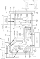
- FIG. 2 is a diagram showing the configuration of a manifold body 11 of the manifold 10.
- the manifold 10 has a manifold body 11 formed of, for example, a metal material such as aluminum, a resin, or the like, and the refrigerant flow path L described with reference to FIG. 1 is formed inside the manifold body 11.
- the manifold 10 is fixed to and restrained by a restrained object of a vehicle.
- the manifold 10 is fixed to a vehicle body support frame 14, which is an example of a restrained object.
- the manifold 10 includes a manifold body 11 and a restraining portion 13, and by fixing the restraining portion 13 to the vehicle body support frame 14, the manifold 10 (manifold body 11) is fixed to and restrained by the vehicle body support frame 14.
- the restrained object to which the manifold 10 is fixed and restrained is not limited to the vehicle body support frame 14, but may be any type of object such as a power module case or a motor case (not shown) mounted on the vehicle, as long as the manifold 10 can be reliably fixed and restrained.
- the compressor 1, cabin condenser 2, water-cooled condenser 3, evaporator 4, battery cooler 5, and accumulator 6 are provided outside the manifold body 11.
- the on-off valve V1, the first expansion valve VE1, and the second expansion valve VE2 are also provided outside the manifold body 11. Note that in FIG. 2, the on-off valve V1, the first expansion valve VE1, and the second expansion valve VE2 are provided outside the manifold body 11, but are shown with solid lines to indicate their respective positions.
- the manifold body 11 has a box shape having a rectangular flat surface (hereinafter referred to as the "principal surface 11s").
- the principal surface 11s of the manifold body 11 is rectangular, and a refrigerant flow path L is formed on the principal surface 11s.
- the four ends constituting the manifold body 11 are referred to as the "first end 12a" (right end in FIG. 2), the “second end 12b” (left end in FIG. 2; an example of an end), the “third end 12c” (lower end in FIG. 2), and the "fourth end 12d” (upper end in FIG. 2; an example of an end).
- the longitudinal direction of the principal surface 11s (the direction parallel to the third end 12c and the fourth end 12d) is simply referred to as the "longitudinal direction”
- the lateral direction of the principal surface 11s (the direction parallel to the first end 12a and the second end 12b) is simply referred to as the "lateral direction”.
- the on-off valve V1, the first expansion valve VE1, and the second expansion valve VE2 are arranged so as to overlap with the manifold body 11 when viewed in a direction perpendicular to the main surface 11s.
- the first expansion valve VE1, the on-off valve V1, and the second expansion valve VE2 are arranged in this order along the longitudinal direction from the first end 12a side.
- the manifold body 11 is formed with an outlet through which the refrigerant F flows out of the manifold body 11 to the first expansion valve VE1, the on-off valve V1, and the second expansion valve VE2.
- the manifold body 11 is also formed with an inlet through which the refrigerant F flows into the manifold body 11 from the first expansion valve VE1, the on-off valve V1, and the second expansion valve VE2.
- the outlet through which the refrigerant F flows from the water-cooled condenser 3 to the on-off valve V1 is referred to as the "outlet H1," and of the inlets, the inlet through which the refrigerant F flows from the on-off valve V1 into the manifold body 11 is referred to as the "inlet H2.”
- the outlet H1 and the inlet H2 are provided to face the on-off valve V1.
- the temperature of the refrigerant F is the highest in the first temperature of the high-temperature fluid F1 flowing from the compressor 1 to the water-cooled condenser 3, the second highest in the second temperature of the first low-temperature fluid F2 flowing from the evaporator 4 and/or the battery cooler 5 to the compressor 1, and the lowest in the third temperature of the second low-temperature fluid F3 flowing from the water-cooled condenser 3 to the evaporator 4 and/or the battery cooler 5.
- the manifold body 11 includes, as refrigerant flow paths L (see FIG.
- a high-temperature flow path LH through which the high-temperature fluid F1 flows from the compressor 1 to the water-cooled condenser 3
- a medium-temperature flow path LM (an example of a low-temperature flow path) through which the medium-temperature first low-temperature fluid F2 flows from the evaporator 4 and/or the battery cooler 5 to the compressor 1
- a low-temperature flow path LL through which the second low-temperature fluid F3 flows from the water-cooled condenser 3 to the evaporator 4 and/or the battery cooler 5.
- the manifold body 11 further includes a medium-low temperature flow path LML (an example of a low temperature flow path) as a refrigerant flow path L, through which a third low temperature fluid F4 (an example of a low temperature fluid) of low to medium temperature flows from the water-cooled condenser 3 to the on-off valve V1.
- a high temperature section 16 the portion where the high temperature flow path LH is arranged is referred to as a high temperature section 16.
- portions other than the high temperature section 16 for example, the portions where the medium temperature flow path LM, the low temperature flow path LL, and the medium-low temperature flow path LML are arranged
- the high temperature section 16 is the portion to the right of the dashed line
- the low temperature section 18 is the portion to the left of the dashed line.
- the high-temperature flow path LH includes a first high-temperature flow path LH1 (an example of a high-temperature flow path) through which the high-temperature fluid F1 flows from the compressor 1 to the cabin condenser 2, and a second high-temperature flow path LH2 (an example of a high-temperature flow path) through which the high-temperature fluid F1 flows from the cabin condenser 2 to the water-cooled condenser 3.
- the first high-temperature flow passage LH1 extends from the first end 12a of the manifold body 11 toward the second end 12b, then bends toward the fourth end 12d, and reaches the fourth end 12d.
- the second high-temperature flow path LH2 extends from the fourth end 12d toward the third end 12c, passes through the first expansion valve VE1, bends toward the second end 12b, and reaches the third end 12c.
- the second high-temperature flow path LH2 is provided so as to straddle the on-off valve V1.
- the outlet H1 for the refrigerant F to the on-off valve V1 is formed at a position facing the on-off valve V1, far from the second high-temperature flow path LH2.
- An inlet H2 is provided between the outlet H1 and the portion straddling the second high-temperature flow path LH2.
- the medium temperature flow path LM includes a first medium temperature flow path LM1 through which the first low temperature fluid F2 flows from the evaporator 4 to the accumulator 6, a second medium temperature flow path LM2 through which the first low temperature fluid F2 flows from the battery cooler 5 to the accumulator 6, and a merging medium temperature flow path LM3 through which the first medium temperature flow path LM1 and the second medium temperature flow path LM2 are connected (the first low temperature fluids F2 merge with each other).
- the first medium temperature flow path LM1 extends from the fourth end 12d toward the third end 12c at an angle to the fourth end 12d, then changes direction midway to become parallel to the second end 12b (including being approximately parallel, the same applies below), and extends to the first bend point P1.
- the first medium temperature flow path LM1 bends at the first bend point P1 toward the first end 12a, and reaches the merging medium temperature flow path LM3.
- the second medium temperature flow path LM2 extends from the fourth end 12d toward the third end 12c, parallel to the first medium temperature flow path LM1, to the merging medium temperature flow path LM3.
- the merging medium temperature flow path LM3 extends from the end of the first medium temperature flow path LM1 in the longitudinal direction toward the first end 12a, and connects at the merging point P2 with the refrigerant flow path L that passes from the water-cooled condenser 3 through the on-off valve V1.
- the merging medium temperature flow path LM3 bends toward the fourth end 12d at the merging point P2, and extends in the lateral direction toward the fourth end 12d.
- the merging medium temperature flow path LM3 further bends toward the first end 12a at the second bending point P3, and extends in the longitudinal direction to reach the first end 12a.
- the merging medium temperature flow path LM3 is provided so as to straddle the high temperature flow path LH between the second bending point P3 and the end.
- the medium-low temperature flow path LML is a refrigerant flow path L through which the third low temperature fluid F4 flows from the water-cooled condenser 3 through the on-off valve V1 toward the accumulator 6.
- the medium-low temperature flow path LML extends from the third end 12c toward the fourth end 12d along the short side to the branch point P4.
- the branch point P4 is the position where the refrigerant F from the water-cooled condenser 3 branches into the third low temperature fluid F4 flowing toward the on-off valve V1, the second low temperature fluid F3 flowing toward the evaporator 4, and the second low temperature fluid F3 flowing toward the battery cooler 5.
- the medium-low temperature flow path LML bends toward the first end 12a at the branch point P4, extends longitudinally toward the first end 12a, passes through the on-off valve V1, and reaches the junction P2 with the junction medium temperature flow path LM3.
- the low-temperature flow path LL includes a first low-temperature flow path LL1 (an example of a low-temperature flow path) through which the second low-temperature fluid F3 flows from the water-cooled condenser 3 to the evaporator 4, and a second low-temperature flow path LL2 through which the second low-temperature fluid F3 flows from the water-cooled condenser 3 to the battery cooler 5.
- the base ends of the first low-temperature flow path LL1 and the second low-temperature flow path LL2 are at a branch point P4.
- the first low-temperature flow path LL1 passes through the second expansion valve VE2, extends along the short side direction toward the fourth end 12d, and then changes direction so as to be inclined with respect to the fourth end 12d before reaching the second end 12b.
- the second low-temperature flow path LL2 extends along the short side direction. In the short side direction, the second low-temperature flow path LL2 changes direction so as to be inclined toward the fourth end 12d closer to the fourth end 12d side than the bending point of the first low-temperature flow path LL1, and reaches the corner between the second end 12b and the fourth end 12d.
- the manifold body 11 of the manifold 10 is divided into a high temperature section 16 (to the right of the dashed line in FIG. 2 ) in which the high temperature flow passage LH is disposed, and a low temperature section 18 (to the left of the dashed line in FIG. 2 ) other than the high temperature section 16.
- a high temperature section 16 to the right of the dashed line in FIG. 2
- a low temperature section 18 to the left of the dashed line in FIG. 2
- the restraining section 13 is fixed to the vehicle body support frame 14.
- the restraining section 13 is disposed at a location where the second end 12b and the fourth end 12d adjacent to each other of the manifold body 11 shown in FIG. 2 intersect.
- the restraining section 13 is disposed at an end of the low temperature section 18 of the manifold body 11.
- the manifold 10 is fixed and restrained with respect to the vehicle body support frame 14.
- the location where one restraint portion 13 is disposed may be the center portion of the second end portion 12b, as long as it is provided at a location where the manifold 10 is stably fixed.
- the manifold 10 is fixed to the vehicle body support frame 14 by a single restraint portion 13 disposed in the low temperature portion 18 of the manifold body 11. Since the first cold fluid F2, the second cold fluid F3, and the third cold fluid F4 flow through the low temperature portion 18, the temperature of the low temperature portion 18 is low and the manifold body 11, including the vicinity of the restraint portion 13, contracts. However, since the manifold 10 is fixed to the vehicle body support frame 14 at one location (one restraint portion 13), no tensile stress is generated in the manifold body 11 and the manifold 10 is less likely to break. It is also possible to configure the manifold 10 by disposing only one restraint portion 13 in the high temperature portion 16 of the manifold body 11 instead of the low temperature portion 18.
- a manifold 10 according to a second embodiment will be described with reference to Fig. 3.
- This embodiment differs from the first embodiment in that two restraining portions 13 are provided to fix the manifold 10 to the vehicle body support frame 14.
- the second embodiment has the same configuration as the first embodiment. Therefore, in the description of this embodiment, the same reference numerals are used for the same components as those in the first embodiment, and detailed description of the same components will be omitted.
- one restraining portion 13 is disposed in the low-temperature portion 18 of the manifold body 11, and one restraining portion 13 is also disposed in the high-temperature portion 16 of the manifold body 11.
- the restraining portion 13 in the low-temperature portion 18 is disposed in the same location as in the first embodiment.
- the restraining portion 13 in the high-temperature portion 16 is disposed at the location where the adjacent first end 12a and third end 12c of the manifold body 11 shown in FIG. 3 intersect.
- the manifold 10 is fixed to the vehicle body support frame 14 by the restraint portion 13, one located in each of the high temperature portion 16 and the low temperature portion 18 of the manifold body 11. That is, the manifold 10 is fixed and restrained to the vehicle body support frame 14 at two points. Since the first cold fluid F2, the second cold fluid F3, and the third cold fluid F4 flow through the low temperature portion 18, the temperature of the low temperature portion 18 is low and the manifold body 11 contracts, including the vicinity of the restraint portion 13. However, since the high temperature fluid F1 flows through the high temperature portion 16, the temperature of the high temperature portion 16 is higher than that of the low temperature portion 18 and the manifold body 11 expands, including the vicinity of the restraint portion 13.
- the manifold 10 contracts near the restraint portion 13 in the low temperature portion 18 and expands near the restraint portion 13 in the high temperature portion 16, so that the tensile stress due to the contraction and the compressive stress due to the expansion cancel each other out, and the stress is reduced in the manifold 10 as a whole. That is, in the manifold 10 of this embodiment, the restraint portion 13 arranged in the high temperature portion 16 and the restraint portion 13 arranged in the low temperature portion 18 form a stress reduction structure 20. Due to this stress reduction structure 20, even if the restraint portion 13 is arranged in multiple places (two places), excessive stress is not generated in the manifold body 11, and the manifold 10 is less likely to break.
- a manifold 10 according to a third embodiment will be described with reference to Fig. 4.
- the arrangement of the high temperature section 16 and the low temperature section 18 in the manifold 10 is different from that in the first and second embodiments, and accordingly, the arrangement of the restraint section 13 is also different.
- the configuration is the same as in the first and second embodiments. Therefore, in the description of this embodiment, the same reference numerals are used for parts having the same configuration as in the first and second embodiments, and detailed description of the same configuration is omitted.
- a high temperature section 16 is disposed in the center of the manifold body 11, and low temperature sections 18 are disposed on either side of the high temperature section 16.
- a restraining section 13 is disposed in each of the low temperature sections 18 on either side.
- the two restraining sections 13 disposed in the low temperature section 18 are disposed at the intersection of the adjacent second end 12b and fourth end 12d of the manifold body 11 shown in FIG. 4, and at the intersection of the adjacent first end 12a and fourth end 12d of the manifold body 11.
- the manifold 10 is fixed to the vehicle body support frame 14 by a restraint portion 13 disposed in each of the two low temperature portions 18 of the manifold body 11. That is, the manifold 10 is fixed and restrained to the vehicle body support frame 14 at the two low temperature portions 18. Since low temperature fluid flows through each low temperature portion 18, the temperature of each low temperature portion 18 is low, and the manifold body 11 contracts, including the areas near the two restraint portions 13. However, in this embodiment, since a high temperature portion 16 through which high temperature fluid F1 flows is disposed between the two low temperature portions 18, the temperature of the high temperature portion 16 is higher than that of the low temperature portion 18, and the manifold body 11 expands.
- a stress reduction structure 20 is formed by the high temperature portion 16, the two low temperature portions 18 disposed so as to sandwich the high temperature portion 16, and the restraint portion 13 disposed in each of the two low temperature portions 18. Due to this stress reduction structure 20, even if the restraint portion 13 is disposed in multiple places (two places) in the low temperature portion 18, excessive stress is not generated in the manifold body 11, and the manifold 10 is less likely to break.
- low temperature sections 18 are arranged on both sides of the high temperature section 16, but it may be configured so that two high temperature sections 16 and two low temperature sections 18 are arranged alternately side by side. In this case, it is preferable to arrange one restraint section 13 in each of the high temperature sections 16 and low temperature sections 18. It may also be configured so that two high temperature sections 16 and three low temperature sections 18 are arranged alternately side by side. In this case, it is preferable to arrange one restraint section 13 in each of the low temperature sections 18 on both ends.
- the restraint portion 13 in each of the above embodiments is not limited to the location described in the embodiment. It can be placed at any location as long as tensile stress is not generated.
- the restraint portion 13 may be placed at the location where the second end 12b and the third end 12c of the manifold body 11 intersect.
- the restraint portion 13 of the high temperature portion 16 in the second embodiment may be placed at the location where the first end 12a and the fourth end 12d of the manifold body 11 intersect.
- the restraint portion 13 of the high temperature portion 16 in the third embodiment may be placed at the location where the first end 12a and the third end 12c of the manifold body 11 intersect.
- one restraint section 13 is disposed in each of the high temperature section 16 and the low temperature section 18, but this is not limited to the above.
- the manifold 10 may be configured so that the same number of restraint sections 13 (e.g., two each) are disposed in each of the high temperature section 16 and the low temperature section 18.
- the manifold 10 may be configured so that the number of restraint sections 13 disposed in the high temperature section 16 is different from the number of restraint sections 13 disposed in the low temperature section 18.
- One embodiment of the manifold (10) comprises a manifold body (11) having a high temperature section (16) in which a high temperature flow path (LH) is formed, through which a high temperature fluid (F1) having a first temperature or higher flows, and a low temperature section (18) in which a low temperature flow path (LM, LL, LML) is formed, through which a low temperature fluid (F2, F3, F4) having a second temperature or lower that is lower than the first temperature flows, and a restraint section (13) that restrains the manifold body (11) against a restrained object (14), and at least one restraint section (13) is disposed at an end (12b, 12d) of the low temperature section (18) of the manifold body (11).
- At least one restraint portion (13) is disposed at the end (12b, 12d) of the low-temperature portion (18) of the manifold body (11), so that the manifold (10) is less likely to be damaged.
- the restraint portion (13) is disposed at the end (12b, 12d) of the low-temperature portion (18) of the manifold body (11), the restraint portion (13) does not interfere with the arrangement of the high-temperature flow path (LH) or the low-temperature flow paths (LM, LL, LML).
- the restraint section (13) is arranged only in the low temperature section (18).
- low temperature sections (18) are arranged on both sides of a high temperature section (16), and a restraining section (13) is arranged in each of the low temperature sections (18) on both sides.
- the manifold (10) can be stably fixed to the restrained object (14) because it is fixed to the restrained object (14) by the restraining sections (13) arranged in the low temperature sections (18) on both sides of the manifold body (11).
- the restraint section (13) is also arranged in the high temperature section (16).
- the manifold (10) is restrained at least at two points, the low temperature portion (18) and the high temperature portion (16), so that the manifold (10) can be stably fixed to the restrained object (14). Moreover, because the restraint portion (13) is disposed in the contracting low temperature portion (18) and the expanding high temperature portion (16), no tensile stress is generated in the manifold body (11), and the manifold (10) is less likely to break.
- One embodiment of the manifold (10) comprises a manifold body (11) having a high temperature section (16) in which a high temperature flow path (LH) is formed, through which a high temperature fluid (F1) having a first temperature or higher flows, and a low temperature section (18) in which a low temperature flow path (LM, LL, LML) is formed, through which a low temperature fluid (F2, F3, F4) having a second temperature or lower that is less than the first temperature flows, and a restraining section (13) arranged in the high temperature section (16) and the low temperature section (18) and restraining the manifold body (11) against a restrained object (14), and the restraining section (13) arranged in the low temperature section (18) and the restraining section (13) arranged in the high temperature section (16) form a stress relief structure (20).
- the manifold (10) is restrained at least at two points, the low temperature section (18) and the high temperature section (16), so that the manifold (10) can be stably fixed to the restrained object (14).
- the restraint section (13) is disposed in the contracting low temperature section (18) and the expanding high temperature section (16), forming a stress reduction structure (20) in which the tensile stress due to contraction and the compressive stress due to expansion are offset, so that the stress is reduced in the manifold (10) as a whole, making the manifold (10) less likely to break.
- one restraint section (13) is arranged in each of the high temperature section (16) and the low temperature section (18).
- the manifold (10) is restrained at two points, so that the manifold (10) can be stably restrained to the restrained object (14). Furthermore, even if the manifold (10) is fixed to the restrained object (14) at two points, it contracts near the restrained portion (13) in the low-temperature portion (18) and expands near the restrained portion (13) in the high-temperature portion (16). This means that the tensile stress caused by the contraction and the compressive stress caused by the expansion cancel each other out, and stress is reduced in the manifold (10) as a whole.
- the same number of restraint sections (13) are arranged in each of the high-temperature section (16) and the low-temperature section (18).
- the same number of restraint sections (13) are arranged in both the high temperature section (16) and the low temperature section (18), so that the tensile stress caused by contraction and the compressive stress caused by expansion can be effectively offset.
- At least one restraint portion (13) is disposed at the end (12b, 12d) closer to the low-temperature flow path (LM, LL, LML) than the high-temperature flow path (LH).
- At least one restraint portion (13) is disposed at the end portion (12b, 12d) closer to the low-temperature flow path (LM, LL, LML) than the high-temperature flow path (LH), so that the manifold (10) is less likely to be damaged.
- At least one restraint portion (13) is disposed at the intersection of two adjacent ends (12b, 12d).
- At least one restraining portion (13) is disposed at the intersection of two adjacent ends (12b, 12d), so that the manifold (10) can be stably fixed to the restrained object (14) against external forces from two directions.
- the high-temperature flow path is at least one of a flow path (LH1) from the compressor (1) to the cabin condenser (2) and a flow path (LH2) from the cabin condenser (2) to the water-cooled condenser (3).
- the manifold (10) having at least one of the flow path (LH1) from the compressor (1) to the cabin condenser (2) and the high-temperature flow path (LH2) from the cabin condenser (2) to the water-cooled condenser (3) can be stably fixed to the restrained object (14).
- the low-temperature flow path is a flow path (LL1) that runs from the water-cooled condenser (3) to the evaporator (4).
- the manifold (10) having a low-temperature flow path (LL1) from the water-cooled condenser (3) to the evaporator (4) can be stably fixed to the restrained object (14).
- This disclosure can be used in manifolds.
Landscapes
- Physics & Mathematics (AREA)
- Thermal Sciences (AREA)
- Engineering & Computer Science (AREA)
- Mechanical Engineering (AREA)
- Arrangement Or Mounting Of Propulsion Units For Vehicles (AREA)
- Air-Conditioning For Vehicles (AREA)
Abstract
Description
まず、図1を参照して、電気自動車、ハイブリット車等の車両に搭載される冷媒回路Cについて説明する。冷媒回路Cは、車両の室内の温度を調整する冷暖房用の冷媒Fが流通する冷媒流路Lによって構成される。冷媒Fは、例えば、ハイドロフルオロカーボン(HFC)、ハイドロフルオロオレフィン(HFO)等である。冷媒流路Lは、後述するマニホールド10が有するマニホールド本体11の内部に設けられる(図2参照)。
続いて、図2を参照して、第1実施形態に係るマニホールド10の構成について説明する。図2は、マニホールド10が有するマニホールド本体11の構成を示す図である。マニホールド10は、例えばアルミニウム等の金属材料、樹脂等を用いて形成されたマニホールド本体11を有し、図1を参照して説明した冷媒流路Lは、マニホールド本体11の内部に形成される。マニホールド10は、車両の被拘束物に固定されて拘束される。本実施形態では、マニホールド10は、被拘束物の一例としての車体支持フレーム14に固定される。マニホールド10は、マニホールド本体11と拘束部13とを備えており、拘束部13を車体支持フレーム14に固定することにより、マニホールド10(マニホールド本体11)は、車体支持フレーム14に対して固定され、拘束される。なお、マニホールド10が固定されて拘束される被拘束物は、車体支持フレーム14だけではなく、車両に搭載された不図示の電源モジュールケースやモータケース等、マニホールド10を確実に固定、拘束できるものであればその種類は問わない。
図1を参照して説明したように、冷媒Fの温度は、コンプレッサ1から水冷コンデンサ3へ向かう高温流体F1の第1温度が最も高く、エバポレータ4及び/又はバッテリクーラ5からコンプレッサ1へ向かう第1低温流体F2の第2温度がその次に高く、水冷コンデンサ3からエバポレータ4及び/又はバッテリクーラ5に向かう第2低温流体F3の第3温度が最も低い。つまり、マニホールド本体11は、コンプレッサ1から水冷コンデンサ3へ向かう高温流体F1が流れる高温流路LHと、エバポレータ4及び/又はバッテリクーラ5からコンプレッサ1へ向かう中温の第1低温流体F2が流れる中温流路LM(低温流路の一例)と、水冷コンデンサ3からエバポレータ4及び/又はバッテリクーラ5へ向かう第2低温流体F3が流れる低温流路LLとを冷媒流路L(図1参照)として含む。
上述したように、マニホールド10のマニホールド本体11は、高温流路LHが配置されている高温部16(図2の一点鎖線よりも右側)と、高温部16以外の低温部18(図2の一点鎖線よりも左側)とに分かれている。本実施形態のマニホールド10においては、マニホールド本体11の低温部18に1つだけ拘束部13が配置されており、拘束部13を車体支持フレーム14に固定している。具体的には、拘束部13は、図2に示されるマニホールド本体11の互いに隣り合う第2端部12bと第4端部12dとが交差する箇所に配置されている。すなわち、拘束部13は、マニホールド本体11の低温部18の端部に配置されている。拘束部13を車体支持フレーム14に固定することにより、マニホールド10は、車体支持フレーム14に対して固定されて拘束される。なお、1つの拘束部13が配置される箇所は、第2端部12bの中央部分でもよく、マニホールド10が安定的に固定される箇所に設ければよい。
次に、第2実施形態に係るマニホールド10について、図3を用いて説明する。本実施形態においては、マニホールド10を車体支持フレーム14に対して固定する拘束部13が2つ配置されている点で第1実施形態と異なる。それ以外は第1実施形態と同様の構成を有している。そのため、本実施形態の説明においては、第1実施形態と同様の構成の箇所については同じ符号を付し、同様の構成に関する詳細な説明を省略する。
次に、第3実施形態に係るマニホールド10について、図4を用いて説明する。本実施形態においては、マニホールド10における高温部16と低温部18の配置が第1,第2実施形態とは異なっており、それに伴い、拘束部13の配置も異なっている。それ以外は第1,第2実施形態と同様の構成を有している。そのため、本実施形態の説明においては、第1,第2実施形態と同様の構成の箇所については同じ符号を付し、同様の構成に関する詳細な説明を省略する。
本開示は、上記した実施形態以外に以下のように構成してもよい(実施形態と同じ機能を有するものには、実施形態と共通の番号、符号を付している)。
Claims (10)
- 第1温度以上の高温流体が流通する高温流路が形成された高温部、及び前記第1温度未満である第2温度以下の低温流体が流通する低温流路が形成された低温部を有するマニホールド本体と、
前記マニホールド本体を被拘束物に対して拘束する拘束部と、を備え、
前記拘束部は、前記マニホールド本体の前記低温部の端部に少なくとも1つ配置されているマニホールド。 - 前記拘束部は、前記低温部にのみ配置されている請求項1に記載のマニホールド。
- 前記拘束部は、前記高温部にも配置されている請求項1に記載のマニホールド。
- 第1温度以上の高温流体が流通する高温流路が形成された高温部、及び前記第1温度未満である第2温度以下の低温流体が流通する低温流路が形成された低温部を有するマニホールド本体と、
前記高温部と前記低温部とに配置され、前記マニホールド本体を被拘束物に対して拘束する拘束部と、を備え、
前記低温部に配置された前記拘束部と前記高温部に配置された前記拘束部とが応力軽減構造を形成しているマニホールド。 - 前記拘束部は、前記高温部と前記低温部とにそれぞれ1つずつ配置されている請求項4に記載のマニホールド。
- 前記拘束部は、前記高温部と前記低温部とにそれぞれ同数配置されている請求項4に記載のマニホールド。
- 前記拘束部は、前記高温流路よりも前記低温流路に近い側の前記端部に少なくとも1つ配置されている請求項1に記載のマニホールド。
- 前記拘束部は、互いに隣り合う2つの前記端部が交差する箇所に少なくとも1つ配置されている請求項1に記載のマニホールド。
- 前記高温流路は、コンプレッサからキャビンコンデンサに向かう流路、及び前記キャビンコンデンサから水冷コンデンサに向かう流路のうちの少なくとも1つである請求項1に記載のマニホールド。
- 前記低温流路は、水冷コンデンサからエバポレータに向かう流路である請求項1に記載のマニホールド。
Priority Applications (3)
| Application Number | Priority Date | Filing Date | Title |
|---|---|---|---|
| CN202480042908.0A CN121398983A (zh) | 2023-06-28 | 2024-04-09 | 歧管 |
| JP2025529458A JPWO2025004493A1 (ja) | 2023-06-28 | 2024-04-09 | |
| EP24831368.6A EP4737147A1 (en) | 2023-06-28 | 2024-04-09 | Manifold |
Applications Claiming Priority (2)
| Application Number | Priority Date | Filing Date | Title |
|---|---|---|---|
| JP2023106334 | 2023-06-28 | ||
| JP2023-106334 | 2023-06-28 |
Publications (1)
| Publication Number | Publication Date |
|---|---|
| WO2025004493A1 true WO2025004493A1 (ja) | 2025-01-02 |
Family
ID=93938585
Family Applications (1)
| Application Number | Title | Priority Date | Filing Date |
|---|---|---|---|
| PCT/JP2024/014364 Ceased WO2025004493A1 (ja) | 2023-06-28 | 2024-04-09 | マニホールド |
Country Status (4)
| Country | Link |
|---|---|
| EP (1) | EP4737147A1 (ja) |
| JP (1) | JPWO2025004493A1 (ja) |
| CN (1) | CN121398983A (ja) |
| WO (1) | WO2025004493A1 (ja) |
Citations (1)
| Publication number | Priority date | Publication date | Assignee | Title |
|---|---|---|---|---|
| JP2019105422A (ja) * | 2017-12-14 | 2019-06-27 | 株式会社デンソー | 車両用ジョイントブロック |
Family Cites Families (1)
| Publication number | Priority date | Publication date | Assignee | Title |
|---|---|---|---|---|
| CN114789635A (zh) | 2021-01-24 | 2022-07-26 | 浙江三花汽车零部件有限公司 | 集成组件以及热管理系统 |
-
2024
- 2024-04-09 WO PCT/JP2024/014364 patent/WO2025004493A1/ja not_active Ceased
- 2024-04-09 CN CN202480042908.0A patent/CN121398983A/zh active Pending
- 2024-04-09 JP JP2025529458A patent/JPWO2025004493A1/ja active Pending
- 2024-04-09 EP EP24831368.6A patent/EP4737147A1/en active Pending
Patent Citations (1)
| Publication number | Priority date | Publication date | Assignee | Title |
|---|---|---|---|---|
| JP2019105422A (ja) * | 2017-12-14 | 2019-06-27 | 株式会社デンソー | 車両用ジョイントブロック |
Also Published As
| Publication number | Publication date |
|---|---|
| CN121398983A (zh) | 2026-01-23 |
| JPWO2025004493A1 (ja) | 2025-01-02 |
| EP4737147A1 (en) | 2026-05-06 |
Similar Documents
| Publication | Publication Date | Title |
|---|---|---|
| US10508865B2 (en) | Heat exchanger | |
| JP4970022B2 (ja) | 複合型熱交換器及び複合型熱交換器システム | |
| EP4494909A1 (en) | Manifold | |
| EP4613514A1 (en) | Vehicle thermal management system and vehicle | |
| US20160375740A1 (en) | Heating and cooling module | |
| JP2012107804A (ja) | 積層型熱交換器、それを用いた熱媒体加熱装置および車両用空調装置 | |
| JP2008180485A (ja) | 熱交換器 | |
| US20200326140A1 (en) | Heat exchanger arrangement and method for producing a heat exchanger arrangement | |
| EP2792988A1 (en) | Integrated heat exchanger for a vehicle | |
| EP4613519A1 (en) | Air conditioning system and internal heat exchanger thereof, vehicle heat management system, and vehicle | |
| WO2024042983A1 (ja) | 冷媒回路ユニット | |
| CN119546469A (zh) | 歧管流体模块 | |
| CN121398983A (zh) | 歧管 | |
| JP2016151235A (ja) | 冷却システム | |
| EP4575371A1 (en) | Manifold | |
| CN112105884B (zh) | 热交换器 | |
| JP2025019381A (ja) | マニホールド | |
| CN118103240A (zh) | 具有至少两个具有不同基面的热交换器的冷却装置、具有冷却装置的机动车 | |
| JP2022187107A (ja) | 冷却器、半導体装置及び電力変換装置 | |
| JP2000304489A (ja) | 熱交換器及び放熱器 | |
| JP4355604B2 (ja) | 熱交換システム | |
| KR20160041284A (ko) | 차량용 쿨링모듈 및 그 제조방법 | |
| WO2024185200A1 (ja) | マニホールド | |
| RU2801368C2 (ru) | Компоновка моторного отсека автотранспортного средства | |
| JP2009074759A (ja) | 車両用熱交換装置 |
Legal Events
| Date | Code | Title | Description |
|---|---|---|---|
| 121 | Ep: the epo has been informed by wipo that ep was designated in this application |
Ref document number: 24831368 Country of ref document: EP Kind code of ref document: A1 |
|
| ENP | Entry into the national phase |
Ref document number: 2025529458 Country of ref document: JP Kind code of ref document: A |
|
| WWE | Wipo information: entry into national phase |
Ref document number: 2025529458 Country of ref document: JP |
|
| WWE | Wipo information: entry into national phase |
Ref document number: 2024831368 Country of ref document: EP |
|
| NENP | Non-entry into the national phase |
Ref country code: DE |
|
| ENP | Entry into the national phase |
Ref document number: 2024831368 Country of ref document: EP Effective date: 20260128 |
|
| ENP | Entry into the national phase |
Ref document number: 2024831368 Country of ref document: EP Effective date: 20260128 |
|
| WWP | Wipo information: published in national office |
Ref document number: 2024831368 Country of ref document: EP |