WO2025004467A1 - ペレット製造装置及びペレット製造方法 - Google Patents
ペレット製造装置及びペレット製造方法 Download PDFInfo
- Publication number
- WO2025004467A1 WO2025004467A1 PCT/JP2024/010354 JP2024010354W WO2025004467A1 WO 2025004467 A1 WO2025004467 A1 WO 2025004467A1 JP 2024010354 W JP2024010354 W JP 2024010354W WO 2025004467 A1 WO2025004467 A1 WO 2025004467A1
- Authority
- WO
- WIPO (PCT)
- Prior art keywords
- strand
- unit
- section
- pellet manufacturing
- extrusion
- Prior art date
- Legal status (The legal status is an assumption and is not a legal conclusion. Google has not performed a legal analysis and makes no representation as to the accuracy of the status listed.)
- Ceased
Links
Images







Classifications
-
- B—PERFORMING OPERATIONS; TRANSPORTING
- B29—WORKING OF PLASTICS; WORKING OF SUBSTANCES IN A PLASTIC STATE IN GENERAL
- B29C—SHAPING OR JOINING OF PLASTICS; SHAPING OF MATERIAL IN A PLASTIC STATE, NOT OTHERWISE PROVIDED FOR; AFTER-TREATMENT OF THE SHAPED PRODUCTS, e.g. REPAIRING
- B29C48/00—Extrusion moulding, i.e. expressing the moulding material through a die or nozzle which imparts the desired form; Apparatus therefor
- B29C48/001—Combinations of extrusion moulding with other shaping operations
- B29C48/0022—Combinations of extrusion moulding with other shaping operations combined with cutting
-
- B—PERFORMING OPERATIONS; TRANSPORTING
- B29—WORKING OF PLASTICS; WORKING OF SUBSTANCES IN A PLASTIC STATE IN GENERAL
- B29B—PREPARATION OR PRETREATMENT OF THE MATERIAL TO BE SHAPED; MAKING GRANULES OR PREFORMS; RECOVERY OF PLASTICS OR OTHER CONSTITUENTS OF WASTE MATERIAL CONTAINING PLASTICS
- B29B7/00—Mixing; Kneading
- B29B7/30—Mixing; Kneading continuous, with mechanical mixing or kneading devices
- B29B7/34—Mixing; Kneading continuous, with mechanical mixing or kneading devices with movable mixing or kneading devices
- B29B7/38—Mixing; Kneading continuous, with mechanical mixing or kneading devices with movable mixing or kneading devices rotary
-
- B—PERFORMING OPERATIONS; TRANSPORTING
- B29—WORKING OF PLASTICS; WORKING OF SUBSTANCES IN A PLASTIC STATE IN GENERAL
- B29B—PREPARATION OR PRETREATMENT OF THE MATERIAL TO BE SHAPED; MAKING GRANULES OR PREFORMS; RECOVERY OF PLASTICS OR OTHER CONSTITUENTS OF WASTE MATERIAL CONTAINING PLASTICS
- B29B7/00—Mixing; Kneading
- B29B7/30—Mixing; Kneading continuous, with mechanical mixing or kneading devices
- B29B7/58—Component parts, details or accessories; Auxiliary operations
-
- B—PERFORMING OPERATIONS; TRANSPORTING
- B29—WORKING OF PLASTICS; WORKING OF SUBSTANCES IN A PLASTIC STATE IN GENERAL
- B29B—PREPARATION OR PRETREATMENT OF THE MATERIAL TO BE SHAPED; MAKING GRANULES OR PREFORMS; RECOVERY OF PLASTICS OR OTHER CONSTITUENTS OF WASTE MATERIAL CONTAINING PLASTICS
- B29B7/00—Mixing; Kneading
- B29B7/30—Mixing; Kneading continuous, with mechanical mixing or kneading devices
- B29B7/58—Component parts, details or accessories; Auxiliary operations
- B29B7/72—Measuring, controlling or regulating
-
- B—PERFORMING OPERATIONS; TRANSPORTING
- B29—WORKING OF PLASTICS; WORKING OF SUBSTANCES IN A PLASTIC STATE IN GENERAL
- B29B—PREPARATION OR PRETREATMENT OF THE MATERIAL TO BE SHAPED; MAKING GRANULES OR PREFORMS; RECOVERY OF PLASTICS OR OTHER CONSTITUENTS OF WASTE MATERIAL CONTAINING PLASTICS
- B29B9/00—Making granules
- B29B9/02—Making granules by dividing preformed material
- B29B9/06—Making granules by dividing preformed material in the form of filamentary material, e.g. combined with extrusion
-
- B—PERFORMING OPERATIONS; TRANSPORTING
- B29—WORKING OF PLASTICS; WORKING OF SUBSTANCES IN A PLASTIC STATE IN GENERAL
- B29C—SHAPING OR JOINING OF PLASTICS; SHAPING OF MATERIAL IN A PLASTIC STATE, NOT OTHERWISE PROVIDED FOR; AFTER-TREATMENT OF THE SHAPED PRODUCTS, e.g. REPAIRING
- B29C48/00—Extrusion moulding, i.e. expressing the moulding material through a die or nozzle which imparts the desired form; Apparatus therefor
- B29C48/25—Component parts, details or accessories; Auxiliary operations
- B29C48/88—Thermal treatment of the stream of extruded material, e.g. cooling
- B29C48/911—Cooling
-
- B—PERFORMING OPERATIONS; TRANSPORTING
- B29—WORKING OF PLASTICS; WORKING OF SUBSTANCES IN A PLASTIC STATE IN GENERAL
- B29C—SHAPING OR JOINING OF PLASTICS; SHAPING OF MATERIAL IN A PLASTIC STATE, NOT OTHERWISE PROVIDED FOR; AFTER-TREATMENT OF THE SHAPED PRODUCTS, e.g. REPAIRING
- B29C2948/00—Indexing scheme relating to extrusion moulding
- B29C2948/92—Measuring, controlling or regulating
- B29C2948/92009—Measured parameter
- B29C2948/92209—Temperature
-
- B—PERFORMING OPERATIONS; TRANSPORTING
- B29—WORKING OF PLASTICS; WORKING OF SUBSTANCES IN A PLASTIC STATE IN GENERAL
- B29C—SHAPING OR JOINING OF PLASTICS; SHAPING OF MATERIAL IN A PLASTIC STATE, NOT OTHERWISE PROVIDED FOR; AFTER-TREATMENT OF THE SHAPED PRODUCTS, e.g. REPAIRING
- B29C2948/00—Indexing scheme relating to extrusion moulding
- B29C2948/92—Measuring, controlling or regulating
- B29C2948/92323—Location or phase of measurement
- B29C2948/92438—Conveying, transporting or storage of articles
-
- B—PERFORMING OPERATIONS; TRANSPORTING
- B29—WORKING OF PLASTICS; WORKING OF SUBSTANCES IN A PLASTIC STATE IN GENERAL
- B29C—SHAPING OR JOINING OF PLASTICS; SHAPING OF MATERIAL IN A PLASTIC STATE, NOT OTHERWISE PROVIDED FOR; AFTER-TREATMENT OF THE SHAPED PRODUCTS, e.g. REPAIRING
- B29C48/00—Extrusion moulding, i.e. expressing the moulding material through a die or nozzle which imparts the desired form; Apparatus therefor
- B29C48/03—Extrusion moulding, i.e. expressing the moulding material through a die or nozzle which imparts the desired form; Apparatus therefor characterised by the shape of the extruded material at extrusion
- B29C48/04—Particle-shaped
-
- B—PERFORMING OPERATIONS; TRANSPORTING
- B29—WORKING OF PLASTICS; WORKING OF SUBSTANCES IN A PLASTIC STATE IN GENERAL
- B29C—SHAPING OR JOINING OF PLASTICS; SHAPING OF MATERIAL IN A PLASTIC STATE, NOT OTHERWISE PROVIDED FOR; AFTER-TREATMENT OF THE SHAPED PRODUCTS, e.g. REPAIRING
- B29C48/00—Extrusion moulding, i.e. expressing the moulding material through a die or nozzle which imparts the desired form; Apparatus therefor
- B29C48/03—Extrusion moulding, i.e. expressing the moulding material through a die or nozzle which imparts the desired form; Apparatus therefor characterised by the shape of the extruded material at extrusion
- B29C48/05—Filamentary, e.g. strands
Definitions
- This disclosure relates to a pellet manufacturing device and a pellet manufacturing method.
- Patent Document 1 shows a pellet manufacturing device.
- the strands discharged from the die are solidified in a cooling tank and then sent to a strand cutter to be cut.
- Patent Document 1 does not disclose a configuration for bringing the tip of the strand up to the strand cutter in the preparation stage before the start of pellet production. If a user manually transports the strand to the strand cutter and then starts production, the magnitude of the external force acting on the strand will differ depending on the user's skill, which may result in variation in the strand diameter. For this reason, there is room for improvement in the handling of the strand in the preparation stage before the start of pellet production.
- the present disclosure has been made to solve these problems, and aims to prevent variation in strand diameter during the preparation stage before pellet production begins.
- the gripping unit grips the strand extruded from the extrusion unit.
- the moving unit moves the gripping unit.
- the pellet manufacturing method includes a step of gripping the strand extruded from the extrusion section with a gripping section, and a step of moving the strand to the cutting section by moving the gripping section with a moving section.
- the pellet manufacturing device disclosed herein can prevent variation in strand diameter during the preparation stage before pellet manufacturing begins.
- the pellet manufacturing method disclosed herein can prevent variation in strand diameter during the preparation stage before pellet manufacturing begins.
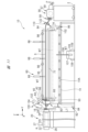
- FIG. 1 is a front view showing a pellet manufacturing apparatus according to an embodiment of the present disclosure.
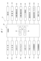
- FIG. 2 is a block diagram of the pellet manufacturing apparatus of FIG. 1.
- FIG. 2 is a front view showing a state in which pellets are produced using the pellet production apparatus of FIG. 1.
- 2 is a plan view showing a state in which molten resin is extruded from a die of the pellet production apparatus of FIG. 1 to form strands.
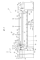
- FIG. FIG. 2 is an enlarged front view of a conveying section of the pellet manufacturing apparatus of FIG. 1.
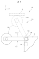
- FIG. 2 is an enlarged front view of an upstream support portion of the pellet manufacturing apparatus of FIG. 1 .
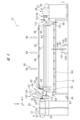
- FIG. 2 is an enlarged front view of a downstream support portion of the pellet manufacturing apparatus of FIG. 1 .
- FIG. 2 is a front view showing a state in which an operation check is being performed before starting pellet production in the pellet production apparatus of FIG. 1.
- FIG. 2 is a front view showing a state in which the pellet production apparatus of FIG. 1 has started an operation of transporting a strand before starting pellet production.
- FIG. 2 is a front view showing a state in the middle of an operation of transporting a strand before starting pellet production in the pellet production apparatus of FIG. 1.
- FIG. 2 is a front view showing a state in which the operation of conveying the strands in the pellet manufacturing apparatus of FIG. 1 has been completed.
- FIG. 11 is a front view showing a pellet manufacturing apparatus according to a first modified example.
- FIG. 11 is a cross-sectional view showing a conveying section of a pellet manufacturing device according to a second modified example.
- Fig. 1 shows a pellet manufacturing apparatus 10 according to the present embodiment.
- Fig. 2 shows a block diagram of each component of the pellet manufacturing apparatus 10. As shown in Fig. 1, the pellet manufacturing apparatus 10 is installed on a floor 2 of a factory. In the following, each direction will be defined and the arrangement of each component will be described assuming that the floor 2 is a horizontal plane.
- a pedestal 14, which will be described later, is provided on the floor 2.
- the pedestal 14 has an upper surface 14A.
- the pellet manufacturing device 10 includes an extrusion unit 20, a control unit 30, a gripping unit 42, a moving unit 50, and a strand cutter 56.
- the pellet manufacturing device 10 includes an operation panel 12, an upstream cutter 16, a cooling unit 60 (FIG. 1), a water tank position detection unit 82, a water tank position change unit 86, a support unit 110 (FIG. 1), and a measurement unit 130.
- the configuration other than that shown in FIG. 2 will be described later.
- the operation of the pellet manufacturing device 10 is started, stopped, and set by the user through the operation panel 12.
- the operation panel 12 is, for example, a touch panel that allows information to be input and displayed.
- pre-extrusion of the strand S is performed as one of the preparation steps before the production of the pellet P (FIG. 3) begins.
- the pre-extrusion of the strand S will be described later.
- the strand S extruded from the extrusion section 20 is cooled in the cooling section 60 and transported to the strand cutter 56 by the gripping section 42 and the moving section 50. Note that the transport of the strand S by the gripping section 42 and the moving section 50 is performed after the strand S has been provisionally extruded.
- the production of pellets P is started in the pellet production apparatus 10
- the strand S extruded from the extrusion section 20 is transported while being cooled in the cooling section 60, and is cut by the strand cutter 56 to form pellets P.
- the production of pellets P using the pellet production apparatus 10 involves two stages: a pre-production preparation stage and a production stage.
- the horizontal direction from the extrusion section 20 toward the strand cutter 56 is referred to as the Y direction.
- the direction perpendicular to the Y direction and vertical is referred to as the Z direction.
- the direction perpendicular to both the Y direction and the Z direction is referred to as the X direction.
- the Y direction is an example of a conveying direction of the strand S.
- the X direction is an example of a crossing direction that crosses the Y direction.
- the tip side of the arrow Y corresponds to the downstream side of the conveying direction of the strand S.
- the base end side of the arrow Y corresponds to the upstream side of the conveying direction of the strand S.
- the tip side of the arrow Z corresponds to the upper side in the vertical direction.
- the base end side of the arrow Z corresponds to the lower side in the vertical direction.
- the tip side of the arrow X corresponds to the front side of the pellet manufacturing device 10.
- the base end side of the arrow X corresponds to the rear side of the pellet manufacturing device 10.
- the specific configuration of the pellet manufacturing device 10 will be described below.
- the extrusion section 20 includes a drive section 22, a cylinder 24, an input section 27, a die 28, and an upstream cutter 16.
- the drive section 22 is configured to include, for example, a motor and a reducer.
- the cylinder 24 is a hollow member extending with the Y direction as its axial direction.
- a screw 25 is provided in the hollow part of the cylinder 24, and a heater 26 is provided on the outer surface or inside.
- the screw 25 is disposed with the Y direction as its axial direction, and is rotated by the drive section 22.
- the number of screws 25 may be either one or more.
- the feed section 27 is connected to the inside of the cylinder 24.
- the resin material that is the raw material for the pellets P ( Figure 3) is fed into the feed section 27.
- a thermoplastic resin can be used as the resin material.
- a thermoplastic resin can be used as the thermoplastic resin, such as polyethylene, polypropylene, polyamide, polyethylene terephthalate, polyimide, polyether ether ketone, polystyrene, polyvinyl chloride, polycarbonate, polymethyl methacrylate, acrylonitrile butadiene styrene resin, polybutylene terephthalate resin, and biodegradable resins (PLA, PBS, PBAT). These resins can be used alone or as a mixture of multiple types.
- the operation of the extrusion section 20 is controlled by the control section 30 (Fig. 2), which will be described later.
- the raw material fed into the cylinder 24 is kneaded by the rotation of the screw 25 and melted by the heat from the heater 26.
- the molten resin material (hereinafter referred to as molten resin R) is transferred to the die 28.
- the die 28 has a plurality of through holes 28A spaced apart in the X direction.
- the molten resin R is extruded from the through holes 28A to become string-like strands S.
- the extrusion unit 20 extrudes the molten resin R as string-like strands S.
- FIG. 4 shows three strands S (S1, S2, S3) extruded from the extrusion unit 20 as an example.
- the X-direction diameter of strand S1 is W1
- the X-direction diameter of strand S2 is W2
- the X-direction diameter of strand S3 is W3.
- the respective sizes of diameters W1, W2, and W3 are measured by a measuring unit 130 (FIG. 2) described below.
- the control unit 30 is a personal computer, and includes a CPU (Central Processing Unit) 32 and a memory 34.
- the CPU 32 and the memory 34 are connected to a common bus 33.
- the CPU 32 executes a program stored in the memory 34, thereby realizing various processes of the pellet manufacturing apparatus 10.
- the control unit 30 can send and receive information to the operation panel 12, the upstream cutter 16, the extrusion unit 20, the gripping unit 42, the moving unit 50, the strand cutter 56, the upstream shower 64, the downstream shower 66, the water tank position detection unit 82, and the water tank position change unit 86. Furthermore, the control unit 30 can send and receive information to the roller lifting unit 92, the temperature measurement unit 102, the temperature change unit 104, the upstream drive unit 114, the downstream drive unit 124, and the measurement unit 130.
- the gripping portion 42 has a support frame 44, bearings 45A and 45B, a roller pair 46, and a bearing drive portion 49.
- the support frame 44 has a vertical wall portion 44A that stands upright in the Z direction. Two vertical wall portions 44A are provided with a gap in the X direction. Note that Fig. 5 shows one vertical wall portion 44A.
- the bearing 45A is fixed to the vertical wall portion 44A.
- the bearing 45B is provided on the vertical wall portion 44A so as to be movable upward and downward in the Z direction.
- the bearing 45B is located above the bearing 45A in the Z direction.
- the roller pair 46 has a lower roller 47 and an upper roller 48.
- the lower roller 47 is arranged with its axial direction in the X direction. Both ends of the lower roller 47 in the X direction are rotatably supported by bearings 45A.
- the lower roller 47 has an outer peripheral surface 47A.
- the upper roller 48 is arranged with its axial direction in the X direction. Both ends of the upper roller 48 in the X direction are rotatably supported by bearings 45B.
- the upper roller 48 has an outer peripheral surface 48A.
- the lower roller 47 and the upper roller 48 are both driven rollers that are not driven by a motor.
- the distance between the part of the outer peripheral surface 47A that is located at the uppermost end in the Z direction and the part of the outer peripheral surface 48A that is located at the lowermost end in the Z direction is defined as the nip distance d.
- the part of the roller pair 46 where the nip distance d is obtained is defined as the nip portion N.
- the bearing drive unit 49 includes, as an example, a cam 49A and a motor 49B that rotates the cam 49A.
- the cam 49A is rotatably mounted on the vertical wall portion 44A. A part of the cam 49A supports the bearing 45B.
- the operation of the motor 49B is controlled by the control unit 30 ( Figure 2).
- the bearing 45B moves upward or downward along the Z direction.
- the bearing drive unit 49 driving the bearing 45B the upper roller 48 can move upward or downward in the Z direction.
- the nip distance d can be changed.
- the nip distance d includes, as an example, a nip distance d1 when the strand S is sandwiched between the lower roller 47 and the upper roller 48, and a nip distance d2 (>d1) when the upper roller 48 is separated from the strand S.
- the nip distances d1 and d2 are preset in the control unit 30 (Fig. 2).
- the nip distance d1 is preset so that the pressure force acting on the strand S in the Z direction is within an allowable range when the roller pair 46 is sandwiching the strand S.
- the nip distance d1 is preset so that the deformation of the strand S is within an allowable range.
- the nip distance d1 is preset so that a force (conveying force) that pulls the strand S downstream in the Y direction acts on the strand S when the moving unit 50 moves.
- the moving unit 50 is provided on a support frame 77 (FIG. 1) described later.
- the moving unit 50 is configured as an electric linear actuator.
- the moving unit 50 includes a guide rail 52 and a carriage 54.
- the guide rail 52 extends in the Y direction.
- the carriage 54 is guided by the guide rail 52, thereby enabling it to move back and forth along the Y direction.
- a vertical wall portion 44A is fixed to the carriage 54.
- the moving unit 50 supports the gripping portion 42 so that it can move in the Y direction.
- the operation of the moving unit 50 is controlled by the control unit 30 (FIG. 2).
- the gripping unit 42 and the moving unit 50 constitute the conveying unit 40.
- the conveying unit 40 grips the strand S and conveys the strand S toward a strand cutter 56 (FIG. 1) described below.
- the point in time when the gripping unit 42 grips the strand S may be any point before, at the same time, or after the point in time when the moving unit 50 starts to move.
- the upstream cutter 16 is located downstream in the Y direction with respect to the die 28 and upstream in the Y direction with respect to a camera 132 described later.
- the upstream cutter 16 includes a blade portion 17 that is movable in the Z direction. The blade portion 17 moves in the Z direction relative to the strand S, thereby enabling the strand S to be cut.
- the upstream cutter 16 cuts the strand S, for example, when the operation of the extrusion portion 20 is confirmed in the preparation stage or when the production of the pellets P is completed.
- the strand cutter 56 is an example of a cutting unit that cuts the strand S transported by the movement of the gripping unit 42.
- the strand cutter 56 has a main body 57, a strand receiving unit 58, and a rotary blade 59.
- the main body 57 is installed on the floor surface 2.
- the strand receiving unit 58 is provided on the upstream side of the main body 57 in the Y direction.
- the strand receiving unit 58 has an upper roller 58A and a lower roller 58B, which are an example of a pair of rotating members.
- the upper roller 58A and the lower roller 58B are each rotatable with the X direction as their axial direction.
- the upper roller 58A and the lower roller 58B pinch the strand S and transport it while rotating.
- the rotary blade 59 is rotatable inside the main body 57 with the X direction as its axial direction.
- the rotational movement of the upper roller 58A and the lower roller 58B and the rotational movement of the rotary blade 59 are controlled by the control unit 30 ( Figure 2).
- the strand cutter 56 receives the strand S transported by the gripping unit 42 at the strand receiving unit 58.
- the strand cutter 56 then cuts the strand S by rotating the rotary blade 59.
- the strand S cut by the rotary blade 59 is discharged to the outside as multiple pellets P.
- the cooling section 60 is located between the extrusion section 20 and the strand cutter 56, and cools the strand S. Specifically, the cooling section 60 has an upper cooling section 62 located above the strand S in the Z direction, and a lower cooling section 72 located below the upper cooling section 62 in the Z direction.
- the upper cooling section 62 has an upstream shower 64 and a downstream shower 66.
- the upstream shower 64 ejects water WT, which is an example of a liquid.
- the upstream shower 64 ejects the water WT toward a portion of the strand S that is downstream in the Y direction from a portion photographed by a camera 132 (described later) and upstream in the Y direction from a portion gripped by the gripping section 42.
- the upstream shower 64 is an example of an upstream cooling section that is located between the extrusion section 20 and the gripping section 42 and cools the strand S.
- the strand S becomes hard by being cooled by the water WT.
- the downstream shower 66 is located downstream in the Y direction relative to the upstream shower 64 and above the strand S in the Z direction. As an example, the downstream shower 66 is provided at three locations spaced apart in the Y direction. Furthermore, the downstream shower 66 is capable of ejecting water WT ( Figure 10) toward the strand S at multiple locations in the X direction.
- the lower cooling section 72 has a water bath 74, an immersion roller 96, a water bath position detection section 82, a water bath position changing section 86, a roller lifting section 92, a temperature measurement section 102, and a temperature changing section 104 (FIG. 2).
- the water tank 74 is placed on the top surface 14A via the water tank position change portion 86.
- the water tank 74 has a rectangular bottom wall portion 75 whose dimension in the Y direction is larger than its dimension in the X direction, and a side wall portion 76 that stands upright in the Z direction upward from the bottom wall portion 75.
- the water tank 74 is formed in a box shape that opens upward in the Z direction, and extends in the Y direction.
- the water tank 74 is an example of a storage tank that stores water WT.
- a support frame 77 extending in the Y direction is attached to the side wall portion 76.
- guide frames 93, 94 which will be described later, are attached to the side wall portion 76.
- the cooling water flows from downstream to upstream in the direction of movement of the strand S, and the water temperature is adjusted so that the temperature on the upstream side becomes the set temperature.
- the laser receiver 84 is fixed to the floor surface 2 so that the surface that receives the laser light LT is located at the top end in the Z direction.
- receives receives
- the laser receiver 84 detects that the upstream end of the water tank 74 in the Y direction is located at the upstream end in the Y direction of its movable range.
- the laser receiver 84 does not receive the laser light LT, it is determined that the water tank 74 is shifted downstream in the Y direction.
- the downstream position of the water tank 74 in the Y direction may be detected based on the amount of operation of the water tank position change unit 86, which will be described later.
- water tank position changing unit 86 is an example of a position changing unit.
- Water tank position changing unit 86 is provided on bottom wall 75 and placed on top surface 14A.
- Water tank position changing unit 86 changes the position of water tank 74 in the Y direction based on the detection result of the position of water tank 74 in the Y direction detected by water tank position detection unit 82.
- Water tank position changing unit 86 has, as an example, an upstream drive roller 87A, a downstream drive roller 87B, and a plurality of driven rollers 87C.
- the operation of water tank position changing unit 86 is controlled by control unit 30 (Fig. 2).
- the upstream drive roller 87A When the upstream drive roller 87A is rotated, the water tank 74 is moved upstream in the Y direction.
- the downstream drive roller 87B When the downstream drive roller 87B is rotated, the water tank 74 is moved downstream in the Y direction a preset distance.
- Multiple driven rollers 87C support the water tank 74 so that it can move in the Y direction.
- the roller lifting unit 92 has guide frames 93 and 94, a plurality of lifting frames 95, and a plurality of immersion rollers 96.
- the guide frames 93 and 94 are attached to the side wall portion 76 and extend in the Z direction.
- the lifting frame 95 extends in the Y direction. Both ends of the lifting frame 95 in the Y direction are supported by the guide frames 93 and 94.
- the guide frames 93 and 94 and the lifting frame 95 are configured as linear actuators. That is, the lifting frame 95 can rise and fall along the Z direction.
- the multiple immersion rollers 96 are an example of immersion members, and each extends with its axial direction in the X direction.
- the multiple immersion rollers 96 are arranged at intervals in the Y direction. Both ends of the multiple immersion rollers 96 in the X direction are rotatably supported by the multiple lifting frames 95.
- the multiple immersion rollers 96 are lowered in accordance with the lowering movement of the lifting frame 95, thereby coming into contact with the strand S and immersing the strand S in the water WT of the water tank 74. In this way, the multiple immersion rollers 96 are positioned between the extrusion section 20 and the strand cutter 56, and are configured to immerse the strand S in the water WT.
- the temperature measuring unit 102 is provided in the water tank 74.
- the temperature measuring unit 102 measures the temperature of the water WT contained in the water tank 74.
- the measured temperature data is sent to the control unit 30 (FIG. 2).
- the temperature changing unit 104 has a tank 105, a pipe 106, a pump 107, a heater 108, and a cooler 109.
- Water WT is stored inside the tank 105.
- the pipe 106 connects the inside of the tank 105 to the inside of the water tank 74.
- the pump 107 pumps up the water WT in the tank 105 and sends it to the pipe 106.
- the heater 108 is provided so as to be able to heat the water WT in the tank 105.
- the cooler 109 is provided so as to be able to cool the water WT in the tank 105.
- the temperature changing unit 104 changes the temperature of the water WT based on the temperature T1 ( Figure 2) measured by the temperature measuring unit 102. For example, if the preset temperature range is the range between temperature T2 and temperature T3 ( Figure 2) and temperature T1 is lower than temperature T2, the temperature changing unit 104 operates the heater 108 to heat the water WT. Also, if temperature T1 is higher than temperature T3, the temperature changing unit 104 operates the cooler 109 to cool the water WT. In this way, the heated or cooled water WT is supplied to the water tank 74, thereby changing (adjusting) the temperature of the water WT in the water tank 74.
- the support section 110 is located between the extrusion section 20 and the strand cutter 56, and supports the strand S. Specifically, the support section 110 has an upstream support section 112 and a downstream support section 122.
- the upstream support section 112 includes an arm member 113, an upstream drive section 114, a support roller 115, and a connecting pin 116.
- the arm member 113 is a plate member having a rectangular shape when viewed from the X direction. Two arm members 113 are provided spaced apart in the X direction, but Fig. 6 shows one arm member 113. One axial end of the arm member 113 is connected to the corner portion 76A by the connecting pin 116.
- the corner portion 76A is a portion located at the upstream end of the side wall portion 76 in the Y direction and at the upper end in the Z direction.
- the upstream drive unit 114 includes a motor and gears, and rotates the arm member 113 around the connecting pin 116.
- the arm member 113 is an example of a displacement member, and is provided so that its position relative to the strand S can be changed.
- the support roller 115 is rotatably provided at the other end of the arm member 113 in the axial direction.
- the support roller 115 has an outer peripheral surface 115A.
- the support roller 115 supports the strand S by a portion of the outer peripheral surface 115A coming into contact with the strand S. Note that when it is not necessary to support the strand S, the arm member 113 is rotated downward in the Z direction, and the support roller 115 is retracted downward in the Z direction.
- the downstream support section 122 includes an arm member 123, a downstream drive section 124, a support roller 125, and a connecting pin 126.
- the arm member 123 is a plate member having a rectangular shape when viewed from the X direction. Two arm members 123 are provided spaced apart in the X direction, but Fig. 7 shows one arm member 123.
- One axial end of the arm member 123 is connected to the corner portion 76B by the connecting pin 126.
- the corner portion 76B is a portion located at the downstream end of the side wall portion 76 in the Y direction and at the upper end in the Z direction.
- the downstream drive unit 124 includes a motor and gears, and rotates the arm member 123 around the connecting pin 126.
- the arm member 123 is an example of a displacement member, and is provided so that its position relative to the strand S can be changed.
- the support roller 125 is rotatably provided at the other end of the arm member 123 in the axial direction.
- the support roller 125 has an outer peripheral surface 125A.
- the support roller 125 supports the strand S by a portion of the outer peripheral surface 125A coming into contact with the strand S. Note that when it is not necessary to support the strand S, the arm member 123 is rotated downward in the Z direction, and the support roller 125 is retracted downward in the Z direction.
- the measurement unit 130 will be described with reference to Figures 1, 2 and 4.
- the measurement unit 130 includes, as an example, a camera 132 and a calculation unit 134.
- the measurement unit 130 measures the diameter W of the strand S in the X direction.
- the calculation unit 134 may be incorporated in the control unit 30 ( Figure 2).
- the camera 132 photographs the strand S extruded from the die 28 from above in the Z direction.
- the image information acquired by the camera 132 is sent to the calculation unit 134.
- the calculation unit 134 has a CPU, memory, etc., just like the control unit 30.
- the calculation unit 134 then performs binarization processing on the image information to calculate the diameter W1 of the strand S1, the diameter W2 of the strand S2, and the diameter W3 of the strand S3. Furthermore, the calculation unit 134 calculates the average values of the diameters W1, W2, and W3.
- the calculated average value information is sent to the control unit 30.
- the control unit 30 controls the moving speed of the moving unit 50 based on the diameter W of the strand S in the X direction measured by the measuring unit 130. Specifically, when the average value of the diameter W of the strand S in the X direction is smaller than a preset value, the control unit 30 controls the moving speed of the moving unit 50 to decrease. Also, when the average value of the diameter W of the strand S in the X direction is larger than a preset value, the control unit 30 controls the moving speed of the moving unit 50 to increase. When the average value and the preset value for the diameter W of the strand S in the X direction are approximately equal, the control unit 30 controls the moving speed of the moving unit 50 to maintain it.
- a provisional extrusion process of the strand S is performed as a preparation stage before the start of manufacturing.
- the water tank 74 is positioned close to the strand cutter 56.
- the gripping portion 42 is positioned at a position (starting position) closest to the upstream support portion 112.
- the extrusion portion 20 extrudes the molten resin R as the strand S.
- the extruded strand S is imaged by the camera 132 and cooled by the upstream shower 64.
- the control unit 30 performs image analysis (e.g., analysis based on color differences) based on the information captured by the camera 132. This determines whether or not there is foreign matter (dust, etc.) in the strand S. If there is foreign matter in the strand S, the operation of the pellet manufacturing device 10 is stopped and a warning message is displayed on the operation panel 12 ( Figure 2). On the other hand, if there is no foreign matter in the strand S, the extrusion of the strand S is stopped and the extruded strand S is cut by the upstream cutter 16. The cut strand S falls and is collected in a container. Then, the process proceeds to the next step.
- image analysis e.g., analysis based on color differences
- foreign matter in the strand S refers to any object that may affect the operation of the strand cutter 56, specifically solid objects such as metal powder that may wear down the strand cutter 56. Gel-like objects and unmelted objects are not included in the category of "foreign matter" because there is no need to stop the extrusion of the strand S.
- the water tank position change unit 86 operates to move the water tank 74 upstream in the Y direction.
- the water tank 74 stops moving when the laser receiver 84 receives the laser light LT.
- the molten resin R is then extruded from the extrusion unit 20 as a string-like strand S (an example of a process for extruding a strand S).
- the upstream drive unit 114 (FIG. 2) is driven, causing the upstream support unit 112 to support the strand S.
- the extruded strand S passes between the lower roller 47 and the upper roller 48, which is retracted upward, and advances downstream in the Y direction.
- the cam 49A is rotated. This causes the position of the upper roller 48 to lower, so that the strand S is sandwiched between the roller pair 46 (an example of the process in which the strand S is gripped by the gripping portion 42).
- the force with which the gripping portion 42 grips the strand S is kept to the minimum force that allows the strand S to move downstream in the Y direction. Therefore, even if the strand S is deformed by the action of the gripping portion 42, the deformed portion of the strand S is limited to the portion gripped by the gripping portion 42. In other words, the portion not gripped by the gripping portion 42 is less likely to be deformed.
- the moving unit 50 moves the gripping unit 42 toward the strand cutter 56.
- a plurality of downstream showers 66 spray water WT onto the strand S, thereby cooling the strand S.
- the strand S moved by the moving unit 50 is moved (transported) in a harder state compared to before cooling.
- the gripping unit 42 that has gripped the strand S is moved to the strand cutter 56 (an example of a process in which the gripping unit 42 is moved by the moving unit 50 to transport the strand S to the strand cutter 56).
- the downstream drive portion 124 (FIG. 2) is driven, causing the downstream support portion 122 to support the strand S. Then, the tip portion (downstream end portion) of the strand S enters the strand receiving portion 58 as the moving portion 50 moves. In this manner, the tip portion of the strand S is handed over to the strand receiving portion 58.
- the transportation of the strand S in the preparation process is completed.
- the upper roller 48 is moved upward in the Z direction before the multiple immersion rollers 96 (FIG. 11) start to descend.
- the gripping portion 42 is moved by the moving portion 50 to the upstream end (start position) of the guide rail 52 in the Y direction.
- the roller lifting section 92 performs a lowering operation.
- the strand S is immersed in the water WT in the water tank 74 by the multiple immersion rollers 96 and cooled.
- the operation of the multiple downstream showers 66 is stopped.
- the manufacturing process is started. Specifically, the extrusion and movement of the strand S is resumed, and the strand S is cut by the strand cutter 56 (an example of a process in which the strand cutter 56 cuts the strand S).
- multiple pellets P are formed. The formed multiple pellets P are collected.
- the gripping unit 42 grips the strand S extruded from the extrusion unit 20.
- the moving unit 50 moves the gripping unit 42. This causes the strand S to be automatically transported to the strand cutter 56.
- the strand cutter 56 cuts the strand S to produce multiple pellets P. In this way, by automating the transport of the strand S to the strand cutter 56 in the preparation stage before the start of the production of pellets P, the variation in the external force acting on the strand S is suppressed, and therefore the occurrence of variation in the diameter W of the strand S can be suppressed.
- the roller pair 46 rotates in a driven manner, thereby reducing the frictional force acting on the surface where the roller pair 46 and the strand S come into contact. This makes it possible to prevent the tensile force acting on the strand S from becoming greater than necessary.
- the cooling section 60 cools the strand S, which promotes hardening of the strand S. This makes it possible to prevent the strand S from deforming during transport.
- the cooling section 60 has an upstream shower 64. This makes it possible to harden the strand S, which is at a relatively high temperature immediately after being extruded from the extrusion section 20, by cooling it with the upstream shower 64, thereby preventing the strand S from deforming during transport.
- the strand S is immersed in the water WT in the water tank 74 between the extrusion section 20 and the strand cutter 56.
- the temperature of the immersed strand S is reduced by heat exchange with the water WT. This allows the strand S to be cooled in a shorter time than when the strand S is cooled by air.
- the water tank position detection unit 82 detects the position of the water tank 74 relative to the position of the extrusion unit 20.
- the water tank position change unit 86 then changes the position of the water tank 74 based on the detection result of the position of the water tank 74 detected by the water tank position detection unit 82. For example, if the position of the water tank 74 is too far away from the position of the extrusion unit 20, the water tank 74 is moved closer to the extrusion unit 20. If the position of the water tank 74 is too close to the position of the extrusion unit 20, the water tank 74 is moved away from the extrusion unit 20. In this way, the distance between the extrusion unit 20 and the water tank 74 can be automatically managed.
- the temperature change unit 104 changes the temperature of the water WT based on the temperature measured by the temperature measurement unit 102. For example, if the temperature of the water WT rises due to a change in the temperature of the environment in which the pellet manufacturing device 10 is installed, the temperature of the water WT can be lowered using the cooler 109. If the temperature of the water WT drops, the temperature of the water WT can be raised using the heater 26. This makes it possible to manage the temperature of the water WT.
- the support section 110 supports the strand S between the extrusion section 20 and the strand cutter 56. This makes it possible to prevent the strand S being transported toward the strand cutter 56 from being deformed during transport.
- the support rollers 115, 125 come into contact with the strand S.
- the positions of the arm members 113, 123 continue to be changed even after the support rollers 115, 125 come into contact with the strand S.
- the contact positions of the support rollers 115, 125 with the strand S change in the circumferential direction as they rotate. This keeps the frictional force acting on the strand S low compared to a configuration in which the support rollers 115, 125 do not rotate, and therefore prevents the strand S from being pulled by the support section 110.
- the measuring unit 130 measures the diameter W of the strand S in the X direction.
- the control unit 30 controls the rotation speed of the strand cutter 56 (upper roller 58A, lower roller 58B ( Figure 3)) based on the diameter W of the strand S in the X direction measured by the measuring unit 130. For example, if the diameter W of the strand S in the X direction is smaller than a preset diameter, the control unit 30 reduces the rotation speed of the upper roller 58A and lower roller 58B. This reduces the tension acting on the strand S in the transport direction, causing the diameter of the strand S in the X direction to approach the set diameter.
- the control unit 30 increases the rotation speed of the upper roller 58A and the lower roller 58B. This increases the tension acting in the Y direction, which is the transport direction of the strand S, and causes the diameter W of the strand S in the X direction to approach the set diameter (the diameter W becomes smaller). In this way, the diameter W of the strand S in the X direction can be brought closer to the set diameter.
- the gripping unit 42 grips the strand S extruded from the extrusion unit 20.
- the moving unit 50 moves the gripping unit 42. This causes the strand S to be automatically transported to the strand cutter 56.
- the strand cutter 56 cuts the strand S to produce multiple pellets P. In this way, by automating the transport of the strand S to the strand cutter 56 in the preparation stage before the start of production of pellets P, variation in the external force acting on the strand S is suppressed, and therefore variation in the diameter W of the strand S can be suppressed.
- the transport of the strand S to the strand cutter 56 is automated in the preparation stage before the start of the production of the pellets P.
- This makes it possible to optimize the operating conditions and improve the quality of the pellets P, compared to a configuration in which a skilled technician manually adjusts the operating conditions of the device after observing the resin temperature and the discharge state of the strands from the strand die.
- By making it possible to optimize the operating conditions it becomes possible to suppress the generation of waste in the early stages of molding the strands S.
- By making it possible to improve the quality of the pellets P it becomes possible to strand low-viscosity resin.
- FIG. 12 shows a pellet manufacturing apparatus 140.
- the pellet manufacturing apparatus 140 has a base 142 instead of the water tank 74 and the water tank position changing unit 86 (FIG. 1).
- the pellet manufacturing apparatus 140 is an apparatus in which the strand S is not immersed in the water WT.
- the strand S extruded from the extrusion unit 20 is cooled by the water WT of the upstream shower 64, and then moved to the strand cutter 56 by the moving unit 50 while being held by the holding unit 42.
- the strand S is further cooled by receiving the water WT of the downstream shower 66 while being moved by the moving unit 50.
- the strand S reaches the strand cutter 56 in a hardened state, so that deformation of the strand S can be suppressed in the preparation stage before production.
- the pellet manufacturing apparatus 10 FIG. 1
- the strand S is cut by the strand cutter 56 to produce the pellets P. In this manner, a pellet manufacturing apparatus 140 without the water tank 74 may be used.
- ⁇ Modification 2> 13 shows the conveying unit 150.
- the conveying unit 150 is provided in place of the conveying unit 40 (FIG. 1) of the pellet manufacturing apparatus 10.
- the conveying unit 150 has a gripping unit 152 and a moving unit 50.
- the gripping unit 152 includes a support block 154, a movable block 156, and a block driving unit 158.
- the block driving unit 158 includes a motor and gears. The operation of the block driving unit 158 is controlled by the control unit 30 (FIG. 2).
- the support block 154 is fixed to the carriage 54.
- a plurality of grooves 155 are formed in the support block 154.
- the grooves 155 are open toward the upper side in the Z direction and extend in the Y direction. When viewed from the Y direction, the grooves 155 are formed in an inverted trapezoid shape having one bottom surface 155A and two inclined surfaces 155B.
- the movable block 156 is located above the support block 154 in the Z direction.
- the movable block 156 can be raised and lowered in the Z direction by a block drive unit 158.
- a plurality of grooves 157 are formed in the movable block 156.
- the grooves 157 are open toward the lower side in the Z direction and extend in the Y direction. When viewed from the Y direction, the grooves 157 are formed in a trapezoid shape having one bottom surface 157A and two inclined surfaces 157B.
- the strand S extruded from the extrusion section 20 enters multiple grooves 155 and is supported by the support block 154. Then, as the movable block 156 descends, the strand S is sandwiched between the bottom surface 155A, the inclined surface 155B, the bottom surface 157A, and the inclined surface 157B. In other words, the strand S is gripped by the gripping section 152. The gripped strand S is moved in the Y direction by the moving section 50. In this way, the gripping section 152 may have a configuration in which the strand S is gripped by a non-rotating clip-shaped member.
- the pellet manufacturing apparatus 10, 140 may not have the downstream shower 66. Furthermore, when the hardened state of the strand S extruded from the extrusion section 20 is such that the strand S can be moved (conveyed), the upstream shower 64 may not be provided.
- the pellet manufacturing apparatus 10, 140 may have a fixed water tank 74 and may not have the water tank position detection section 82 and the water tank position change section 86.
- the cooling section 60 may not have the temperature measurement section 102 and the temperature change section 104. In other words, the temperature of the water WT in the water tank 74 does not need to be changed.
- the pellet manufacturing apparatus 10, 140 may not have a support unit 110.
- the support unit 110 may not have arm members 113, 123 or support rollers 115, 125.
- a pad that can move in the Z direction or a direction intersecting the Z direction may be provided, and the position of the pad may be changed to change the position of the strand S.
- the measuring unit 130 may not be provided, and the moving unit 50 may be moved at a preset speed.
- the cutting unit is not limited to one having a rotating blade 59 like the strand cutter 56, but may have a blade that rises and falls in the Z direction.
Landscapes
- Engineering & Computer Science (AREA)
- Mechanical Engineering (AREA)
- Physics & Mathematics (AREA)
- Thermal Sciences (AREA)
- Processing And Handling Of Plastics And Other Materials For Molding In General (AREA)
- Manufacturing & Machinery (AREA)
- Extrusion Moulding Of Plastics Or The Like (AREA)
Abstract
Description
図1には、本実施の形態のペレット製造装置10が示されている。図2には、ペレット製造装置10の各構成のブロック図が示されている。図1に示されるように、ペレット製造装置10は、工場の床面2に設置されている。以下では、床面2が水平面であると仮定して、各方向を定義すると共に各構成の配置を説明する。床面2には、後述する台座14が設けられている。台座14は、上面14Aを有する。
図1に示されるように、押出部20は、駆動部22と、シリンダー24と、投入部27と、ダイ28と、上流カッター16とを含む。駆動部22は、例えばモーター及び減速機を含んで構成されている。シリンダー24は、Y方向を軸方向として延びる中空の部材である。シリンダー24の中空部には、スクリュー25が設けられ、外表面もしくは内部にはヒーター26が設けられている。スクリュー25は、Y方向を軸方向として配置されており、駆動部22によって回転される。スクリュー25の本数は、単数、複数のいずれであってもよい。
図2に示されるように、制御部30は、パーソナルコンピュータであり、CPU(Central Processing Unit)32及びメモリ34を有する。CPU32及びメモリ34は、共通のバス33に接続されている。メモリ34に記憶されたプログラムをCPU32が実行することによって、ペレット製造装置10の各種の処理が実現される。
図5に示されるように、掴み部42は、支持フレーム44と、軸受45A及び軸受45Bと、ローラー対46と、軸受駆動部49と、を有する。支持フレーム44は、Z方向に直立した縦壁部44Aを有する。縦壁部44Aは、X方向に間隔をあけて2つ設けられている。なお、図5では、1つの縦壁部44Aが示されている。軸受45Aは、縦壁部44Aに固定されている。軸受45Bは、Z方向の上側及び下側に移動可能となるように、縦壁部44Aに設けられている。軸受45Bは、軸受45Aに対してZ方向の上側に位置している。
図5に示されるように、移動部50は、後述する支持フレーム77(図1)に設けられている。移動部50は、一例として、電動式のリニアアクチュエータとして構成されている。移動部50は、ガイドレール52と、キャリッジ54とを含む。ガイドレール52は、Y方向に延びている。キャリッジ54は、ガイドレール52に案内されることで、Y方向に沿った往復移動が可能となっている。キャリッジ54には、縦壁部44Aが固定されている。これにより、移動部50は、掴み部42をY方向に移動可能に支持している。移動部50の動作は、制御部30(図2)によって制御される。
図3に示されるように、上流カッター16は、ダイ28に対するY方向の下流側で且つ後述するカメラ132に対するY方向の上流側に位置する。上流カッター16は、Z方向に移動可能な刃部17を含む。刃部17がストランドSに対してZ方向に移動することで、ストランドSを切断可能となっている。なお、上流カッター16がストランドSを切断する時点としては、例えば、準備段階での押出部20の動作確認時点や、ペレットPの製造が終了した時点がある。
図3に示されるように、ストランドカッター56は、掴み部42の移動によって搬送されたストランドSを切断する切断部の一例である。ストランドカッター56は、本体部57と、ストランド受部58と、回転刃59とを有する。本体部57は、床面2に設置されている。ストランド受部58は、本体部57のY方向の上流側部分に設けられている。ストランド受部58は、一対の回転部材の一例である上ローラー58Aと下ローラー58Bとを有する。
図3に示されるように、冷却部60は、押出部20とストランドカッター56との間に位置し、ストランドSを冷却する。具体的には、冷却部60は、ストランドSに対してZ方向の上側に位置する上冷却部62と、上冷却部62に対してZ方向の下側に位置する下冷却部72と、を有する。
上冷却部62は、上流シャワー64と、下流シャワー66と、を有する。上流シャワー64は、液体の一例である水WTを吐出する。また、上流シャワー64は、ストランドSのうち、後述するカメラ132が撮影する部位よりもY方向の下流側の部位で、且つ掴み部42が掴む部位よりもY方向の上流側の部位に向けて、水WTを吐出する。換言すると、上流シャワー64は、押出部20と掴み部42との間に位置しストランドSを冷却する上流冷却部の一例である。ストランドSは、水WTによって冷却されることで硬くなる。
下冷却部72は、水槽74と、浸漬ローラー96と、水槽位置検出部82と、水槽位置変更部86と、ローラー昇降部92と、温度測定部102と、温度変更部104(図2)と、を有する。
図3に示されるように、水槽位置検出部82は、位置検出部の一例である。水槽位置検出部82は、押出部20のY方向の位置に対する水槽74のY方向の位置を検出する。具体的には、水槽位置検出部82は、レーザー送信機83と、レーザー受信機84と、を有する。レーザー送信機83は、水槽74のY方向の上流端部に取り付けられている。レーザー送信機83は、Z方向の下側に向けてレーザー光LTを出射している。
図3に示されるように、水槽位置変更部86は、位置変更部の一例である。水槽位置変更部86は、底壁部75に設けられており、上面14Aに載せられている。水槽位置変更部86は、水槽位置検出部82で検出された水槽74のY方向の位置の検出結果に基づいて、水槽74のY方向の位置を変更する。水槽位置変更部86は、一例として、上流側駆動ローラー87Aと、下流側駆動ローラー87Bと、複数の従動ローラー87Cとを有する。水槽位置変更部86は、制御部30(図2)によって動作が制御される。
図3に示されるように、ローラー昇降部92は、ガイドフレーム93、94と、複数の昇降フレーム95と、複数の浸漬ローラー96とを有する。ガイドフレーム93、94は、側壁部76に取り付けられており、Z方向に延びている。昇降フレーム95は、Y方向に延びている。昇降フレーム95のY方向の両端部は、ガイドフレーム93、94に支持されている。ガイドフレーム93、94及び昇降フレーム95は、リニアアクチュエータとして構成されている。つまり、昇降フレーム95は、Z方向に沿った上昇及び下降が可能である。
図3に示されるように、温度測定部102は、水槽74に設けられている。温度測定部102は、水槽74に収容されている水WTの温度を測定する。測定された温度データは、制御部30(図2)に送られる。
図3に示されるように、温度変更部104は、タンク105と、パイプ106と、ポンプ107と、ヒーター108と、クーラー109とを有する。タンク105の内部には、水WTが貯留されている。パイプ106は、タンク105の内部と水槽74の内部とを接続している。ポンプ107は、タンク105の水WTを汲み上げてパイプ106に送り込む。ヒーター108は、タンク105の水WTを加熱可能に設けられている。クーラー109は、タンク105の水WTを冷却可能に設けられている。
図3に示されるように、支持部110は、押出部20とストランドカッター56との間に位置し、ストランドSを支持する。具体的には、支持部110は、上流側支持部112と、下流側支持部122とを有する。
図6に示されるように、上流側支持部112は、アーム部材113と、上流側駆動部114と、支持ローラー115と、連結ピン116とを備える。アーム部材113は、X方向から見て矩形状の板部材である。アーム部材113は、X方向に間隔をあけて2つ設けられているが、図6では1つのアーム部材113が示されている。アーム部材113の軸方向の一端部は、連結ピン116によって角部76Aに連結されている。角部76Aは、側壁部76のY方向の上流側端部で且つZ方向の上端部に位置する部位である。
図7に示されるように、下流側支持部122は、アーム部材123と、下流側駆動部124と、支持ローラー125と、連結ピン126とを備える。アーム部材123は、X方向から見て矩形状の板部材である。アーム部材123は、X方向に間隔をあけて2つ設けられているが、図7では1つのアーム部材123が示されている。アーム部材123の軸方向の一端部は、連結ピン126によって角部76Bに連結されている。角部76Bは、側壁部76のY方向の下流側端部で且つZ方向の上端部に位置する部位である。
図1、図2及び図4を用いて、計測部130について説明する。計測部130は、一例として、カメラ132と、演算部134とを有する。そして、計測部130は、ストランドSのX方向の直径Wを計測する。なお、演算部134は、制御部30(図2)に組み込まれていてもよい。
ペレット製造装置10では、操作パネル12(図2)で動作の開始が選択された後、動作の停止が選択されるまで、後述する各処理(工程)が自動的に行われる。各処理は、CPU32がメモリ34からプログラムを読み出して展開し、実行することによって行われる。
図12には、ペレット製造装置140が示されている。ペレット製造装置140は、水槽74及び水槽位置変更部86(図1)に替えて、基台142を有している。つまり、ペレット製造装置140は、ストランドSが水WTに浸漬されない方式の装置である。押出部20から押し出されたストランドSは、上流シャワー64の水WTで冷却された後、掴み部42に掴まれた状態で、移動部50によってストランドカッター56まで移動される。ストランドSは、移動部50による移動中に下流シャワー66の水WTを受けることでさらに冷却される。これにより、ストランドSが硬化された状態でストランドカッター56まで到達するので、製造前の準備段階でのストランドSの変形を抑制することができる。つまり、ペレット製造装置10(図1)と同様に、ペレットPの製造開始前の準備段階で、ストランドSの直径Wにばらつきが生じることを抑制することができる。製造開始後は、ストランドSがストランドカッター56により切断されることで、ペレットPが製造される。このように、水槽74が無いペレット製造装置140を用いてもよい。
図13には、搬送部150が示されている。搬送部150は、ペレット製造装置10の搬送部40(図1)に替えて設けられている。搬送部150は、掴み部152と、移動部50とを有する。掴み部152は、支持ブロック154と、可動ブロック156と、ブロック駆動部158と、を備える。ブロック駆動部158は、モーター及びギヤを含む。ブロック駆動部158は、制御部30(図2)によって動作が制御される。
ペレット製造装置10、140では、下流シャワー66が無くてもよい。さらに、押出部20から押し出されたストランドSの硬化状態が、ストランドSを移動(搬送)することが可能な状態である場合は、上流シャワー64が無くてもよい。ペレット製造装置10、140は、水槽74が固定され、水槽位置検出部82及び水槽位置変更部86を有していないものであってもよい。冷却部60は、温度測定部102及び温度変更部104を有していなくてもよい。つまり、水槽74の水WTの温度を変更しなくてもよい。
Claims (11)
- 溶融された樹脂材を紐状のストランドとして押し出す押出部と、
前記押出部から押し出された前記ストランドを掴む掴み部と、
前記掴み部を移動させる移動部と、
前記掴み部の移動によって搬送された前記ストランドを切断する切断部と、
を備える、ペレット製造装置。 - 前記掴み部は、回転可能に設けられ前記ストランドを挟むローラー対を有する、
請求項1に記載のペレット製造装置。 - 前記押出部と前記切断部との間に位置し前記ストランドを冷却する冷却部をさらに備える、
請求項1に記載のペレット製造装置。 - 前記冷却部は、前記押出部と前記掴み部との間に位置し前記ストランドを冷却する上流冷却部を有する、
請求項3に記載のペレット製造装置。 - 前記冷却部は、
液体を収容する収容槽と、
前記押出部と前記切断部との間に位置し前記ストランドを前記液体に浸漬させる浸漬部材と、
を有する、
請求項3に記載のペレット製造装置。 - 前記押出部の位置に対する前記収容槽の位置を検出する位置検出部と、
前記位置検出部で検出された前記収容槽の位置の検出結果に基づいて、前記収容槽の位置を変更する位置変更部と、
をさらに備える、
請求項5に記載のペレット製造装置。 - 前記冷却部は、
前記液体の温度を測定する温度測定部と、
前記温度測定部で測定された温度に基づいて前記液体の温度を変更する温度変更部と、
を有する、
請求項5に記載のペレット製造装置。 - 前記押出部と前記切断部との間に位置し前記ストランドを支持する支持部をさらに備える、
請求項1に記載のペレット製造装置。 - 前記支持部は、
前記ストランドに対する位置を変更可能に設けられた変位部材と、
前記変位部材に回転可能に設けられ、前記ストランドを支持する支持ローラーと、を備える、
請求項8に記載のペレット製造装置。 - 前記切断部は、前記ストランドを挟むと共に回転しながら前記ストランドを搬送する一対の回転部材を有し、
前記ストランドの搬送方向と交差する交差方向の直径を計測する計測部と、
前記計測部で計測された前記ストランドの直径に基づいて前記一対の回転部材の回転速度を制御する制御部と、をさらに備える、
請求項1から請求項9のいずれか1項に記載のペレット製造装置。 - 以下の工程を含む、ペレット製造方法:
(a)溶融された樹脂材を紐状のストランドとして押出部から押し出す工程;
(b)前記押出部から押し出された前記ストランドを掴み部で掴む工程;
(c)前記掴み部を移動部によって移動させることで前記ストランドを切断部まで搬送する工程;
(d)前記切断部が前記ストランドを切断する工程。
Priority Applications (3)
| Application Number | Priority Date | Filing Date | Title |
|---|---|---|---|
| EP24831344.7A EP4714625A1 (en) | 2023-06-29 | 2024-03-15 | Pellet manufacturing device and pellet manufacturing method |
| CN202480032647.4A CN121335788A (zh) | 2023-06-29 | 2024-03-15 | 颗粒制造装置及颗粒制造方法 |
| KR1020257036791A KR20260029273A (ko) | 2023-06-29 | 2024-03-15 | 펠릿제조장치 및 펠릿제조방법 |
Applications Claiming Priority (2)
| Application Number | Priority Date | Filing Date | Title |
|---|---|---|---|
| JP2023107413A JP2025006549A (ja) | 2023-06-29 | 2023-06-29 | ペレット製造装置及びペレット製造方法 |
| JP2023-107413 | 2023-06-29 |
Publications (1)
| Publication Number | Publication Date |
|---|---|
| WO2025004467A1 true WO2025004467A1 (ja) | 2025-01-02 |
Family
ID=93938580
Family Applications (1)
| Application Number | Title | Priority Date | Filing Date |
|---|---|---|---|
| PCT/JP2024/010354 Ceased WO2025004467A1 (ja) | 2023-06-29 | 2024-03-15 | ペレット製造装置及びペレット製造方法 |
Country Status (6)
| Country | Link |
|---|---|
| EP (1) | EP4714625A1 (ja) |
| JP (1) | JP2025006549A (ja) |
| KR (1) | KR20260029273A (ja) |
| CN (1) | CN121335788A (ja) |
| TW (1) | TW202500350A (ja) |
| WO (1) | WO2025004467A1 (ja) |
Citations (3)
| Publication number | Priority date | Publication date | Assignee | Title |
|---|---|---|---|---|
| JPH06502359A (ja) * | 1992-03-12 | 1994-03-17 | リーター・アウトマーティク・ゲゼルシャフト・ミット・ベシュレンクテル・ハフツング | ダイから出てくる溶融熱可塑性ストランドを冷却しかつ粒状にするための装置 |
| JP2001088124A (ja) * | 1999-09-22 | 2001-04-03 | Japan Steel Works Ltd:The | ストランド冷却引取装置 |
| JP2022134497A (ja) | 2021-03-03 | 2022-09-15 | 株式会社日本製鋼所 | 押出装置およびそれに用いられる押出成形用ダイ、監視装置およびプログラム、ストランドの製造方法、ならびに、ストランド径の調整方法 |
-
2023
- 2023-06-29 JP JP2023107413A patent/JP2025006549A/ja active Pending
-
2024
- 2024-03-15 KR KR1020257036791A patent/KR20260029273A/ko active Pending
- 2024-03-15 WO PCT/JP2024/010354 patent/WO2025004467A1/ja not_active Ceased
- 2024-03-15 EP EP24831344.7A patent/EP4714625A1/en active Pending
- 2024-03-15 CN CN202480032647.4A patent/CN121335788A/zh active Pending
- 2024-03-21 TW TW113110548A patent/TW202500350A/zh unknown
Patent Citations (3)
| Publication number | Priority date | Publication date | Assignee | Title |
|---|---|---|---|---|
| JPH06502359A (ja) * | 1992-03-12 | 1994-03-17 | リーター・アウトマーティク・ゲゼルシャフト・ミット・ベシュレンクテル・ハフツング | ダイから出てくる溶融熱可塑性ストランドを冷却しかつ粒状にするための装置 |
| JP2001088124A (ja) * | 1999-09-22 | 2001-04-03 | Japan Steel Works Ltd:The | ストランド冷却引取装置 |
| JP2022134497A (ja) | 2021-03-03 | 2022-09-15 | 株式会社日本製鋼所 | 押出装置およびそれに用いられる押出成形用ダイ、監視装置およびプログラム、ストランドの製造方法、ならびに、ストランド径の調整方法 |
Also Published As
| Publication number | Publication date |
|---|---|
| KR20260029273A (ko) | 2026-03-04 |
| JP2025006549A (ja) | 2025-01-17 |
| TW202500350A (zh) | 2025-01-01 |
| CN121335788A (zh) | 2026-01-13 |
| EP4714625A1 (en) | 2026-03-25 |
Similar Documents
| Publication | Publication Date | Title |
|---|---|---|
| WO2016041449A1 (zh) | 一种熔融堆积3d打印机及其打印方法 | |
| CN1659320A (zh) | 高精度成型丝 | |
| CN1060059A (zh) | 堆积料数量监测方法和设备,板材成型方法和设备以及板材温度测量方法和设备 | |
| CN105216327A (zh) | 一种热塑性颗粒材料的熔融挤出装置及其3d打印方法 | |
| US10654258B2 (en) | Three dimensional printing apparatus and controlling method thereof | |
| KR101005183B1 (ko) | 고무 정량 절단 제어장치 및 이를 포함하는 고무 정량 절단기 | |
| WO2025004467A1 (ja) | ペレット製造装置及びペレット製造方法 | |
| JP7538744B2 (ja) | 押出装置およびそれに用いられる押出成形用ダイ、監視装置およびプログラム、ストランドの製造方法、ならびに、ストランド径の調整方法 | |
| JP2009220443A (ja) | 偏肉樹脂シートの製造方法 | |
| CN107199696A (zh) | 一种基于fdm的3d打印设备 | |
| JP2010188571A (ja) | 偏肉樹脂シートの製造方法および製造装置 | |
| JP6379804B2 (ja) | ラドル給湯装置による計量方法 | |
| KR102950951B1 (ko) | 압출성형장치 및 시스템 | |
| CN106113515B (zh) | 成型系统及应用其的成型方法 | |
| JPWO2020044522A1 (ja) | 粉末床溶融結合装置 | |
| JP2010201712A (ja) | 樹脂シートの製造方法及び製造装置 | |
| JP5405922B2 (ja) | 樹脂丸棒成形方法及び成形用装置 | |
| CN109334001B (zh) | 一种具有双行走机构的三维打印装置的打印控制方法 | |
| JPH04189527A (ja) | 丸棒の押出し成形方法および装置 | |
| TWI922283B (zh) | 擠出成膜裝置 | |
| CN116079024B (zh) | 一种超强超硬变形铝合金方铸锭启铸成型方法和系统 | |
| CN121127358A (zh) | 空气喷嘴装置及树脂片制造装置 | |
| JP7343777B2 (ja) | 廃プラスチック成形物の製造装置、および廃プラスチック成形物の製造方法 | |
| JP4136489B2 (ja) | 未加硫ゴムシート製造装置、及び未加硫ゴムシートの製造方法 | |
| CN211640946U (zh) | 一种涂布挤出装置 |
Legal Events
| Date | Code | Title | Description |
|---|---|---|---|
| 121 | Ep: the epo has been informed by wipo that ep was designated in this application |
Ref document number: 24831344 Country of ref document: EP Kind code of ref document: A1 |
|
| WWE | Wipo information: entry into national phase |
Ref document number: 2024831344 Country of ref document: EP |
|
| ENP | Entry into the national phase |
Ref document number: 2024831344 Country of ref document: EP Effective date: 20251216 |
|
| ENP | Entry into the national phase |
Ref document number: 2024831344 Country of ref document: EP Effective date: 20251216 |
|
| ENP | Entry into the national phase |
Ref document number: 2024831344 Country of ref document: EP Effective date: 20251216 |
|
| ENP | Entry into the national phase |
Ref document number: 2024831344 Country of ref document: EP Effective date: 20251216 |
|
| ENP | Entry into the national phase |
Ref document number: 2024831344 Country of ref document: EP Effective date: 20251216 |
|
| ENP | Entry into the national phase |
Ref document number: 2024831344 Country of ref document: EP Effective date: 20251216 |
|
| NENP | Non-entry into the national phase |
Ref country code: DE |
|
| ENP | Entry into the national phase |
Ref document number: 2024831344 Country of ref document: EP Effective date: 20251216 |
|
| ENP | Entry into the national phase |
Ref document number: 2024831344 Country of ref document: EP Effective date: 20251216 |
|
| WWP | Wipo information: published in national office |
Ref document number: 2024831344 Country of ref document: EP |