WO2025004437A1 - 機械油の使用方法、機械油再生システム、および、機械油再生ユニットの追設方法 - Google Patents
機械油の使用方法、機械油再生システム、および、機械油再生ユニットの追設方法 Download PDFInfo
- Publication number
- WO2025004437A1 WO2025004437A1 PCT/JP2024/005934 JP2024005934W WO2025004437A1 WO 2025004437 A1 WO2025004437 A1 WO 2025004437A1 JP 2024005934 W JP2024005934 W JP 2024005934W WO 2025004437 A1 WO2025004437 A1 WO 2025004437A1
- Authority
- WO
- WIPO (PCT)
- Prior art keywords
- machine oil
- tank
- oil
- additive
- column
- Prior art date
- Legal status (The legal status is an assumption and is not a legal conclusion. Google has not performed a legal analysis and makes no representation as to the accuracy of the status listed.)
- Ceased
Links
Images






Classifications
-
- B—PERFORMING OPERATIONS; TRANSPORTING
- B01—PHYSICAL OR CHEMICAL PROCESSES OR APPARATUS IN GENERAL
- B01J—CHEMICAL OR PHYSICAL PROCESSES, e.g. CATALYSIS OR COLLOID CHEMISTRY; THEIR RELEVANT APPARATUS
- B01J20/00—Solid sorbent compositions or filter aid compositions; Sorbents for chromatography; Processes for preparing, regenerating or reactivating thereof
- B01J20/02—Solid sorbent compositions or filter aid compositions; Sorbents for chromatography; Processes for preparing, regenerating or reactivating thereof comprising inorganic material
- B01J20/06—Solid sorbent compositions or filter aid compositions; Sorbents for chromatography; Processes for preparing, regenerating or reactivating thereof comprising inorganic material comprising oxides or hydroxides of metals not provided for in group B01J20/04
- B01J20/08—Solid sorbent compositions or filter aid compositions; Sorbents for chromatography; Processes for preparing, regenerating or reactivating thereof comprising inorganic material comprising oxides or hydroxides of metals not provided for in group B01J20/04 comprising aluminium oxide or hydroxide; comprising bauxite
-
- B—PERFORMING OPERATIONS; TRANSPORTING
- B01—PHYSICAL OR CHEMICAL PROCESSES OR APPARATUS IN GENERAL
- B01J—CHEMICAL OR PHYSICAL PROCESSES, e.g. CATALYSIS OR COLLOID CHEMISTRY; THEIR RELEVANT APPARATUS
- B01J20/00—Solid sorbent compositions or filter aid compositions; Sorbents for chromatography; Processes for preparing, regenerating or reactivating thereof
- B01J20/02—Solid sorbent compositions or filter aid compositions; Sorbents for chromatography; Processes for preparing, regenerating or reactivating thereof comprising inorganic material
- B01J20/10—Solid sorbent compositions or filter aid compositions; Sorbents for chromatography; Processes for preparing, regenerating or reactivating thereof comprising inorganic material comprising silica or silicate
-
- B—PERFORMING OPERATIONS; TRANSPORTING
- B01—PHYSICAL OR CHEMICAL PROCESSES OR APPARATUS IN GENERAL
- B01J—CHEMICAL OR PHYSICAL PROCESSES, e.g. CATALYSIS OR COLLOID CHEMISTRY; THEIR RELEVANT APPARATUS
- B01J20/00—Solid sorbent compositions or filter aid compositions; Sorbents for chromatography; Processes for preparing, regenerating or reactivating thereof
- B01J20/02—Solid sorbent compositions or filter aid compositions; Sorbents for chromatography; Processes for preparing, regenerating or reactivating thereof comprising inorganic material
- B01J20/10—Solid sorbent compositions or filter aid compositions; Sorbents for chromatography; Processes for preparing, regenerating or reactivating thereof comprising inorganic material comprising silica or silicate
- B01J20/12—Naturally occurring clays or bleaching earth
-
- B—PERFORMING OPERATIONS; TRANSPORTING
- B01—PHYSICAL OR CHEMICAL PROCESSES OR APPARATUS IN GENERAL
- B01J—CHEMICAL OR PHYSICAL PROCESSES, e.g. CATALYSIS OR COLLOID CHEMISTRY; THEIR RELEVANT APPARATUS
- B01J20/00—Solid sorbent compositions or filter aid compositions; Sorbents for chromatography; Processes for preparing, regenerating or reactivating thereof
- B01J20/02—Solid sorbent compositions or filter aid compositions; Sorbents for chromatography; Processes for preparing, regenerating or reactivating thereof comprising inorganic material
- B01J20/10—Solid sorbent compositions or filter aid compositions; Sorbents for chromatography; Processes for preparing, regenerating or reactivating thereof comprising inorganic material comprising silica or silicate
- B01J20/16—Alumino-silicates
- B01J20/18—Synthetic zeolitic molecular sieves
-
- C—CHEMISTRY; METALLURGY
- C10—PETROLEUM, GAS OR COKE INDUSTRIES; TECHNICAL GASES CONTAINING CARBON MONOXIDE; FUELS; LUBRICANTS; PEAT
- C10G—CRACKING HYDROCARBON OILS; PRODUCTION OF LIQUID HYDROCARBON MIXTURES, e.g. BY DESTRUCTIVE HYDROGENATION, OLIGOMERISATION, POLYMERISATION; RECOVERY OF HYDROCARBON OILS FROM OIL-SHALE, OIL-SAND, OR GASES; REFINING MIXTURES MAINLY CONSISTING OF HYDROCARBONS; REFORMING OF NAPHTHA; MINERAL WAXES
- C10G25/00—Refining of hydrocarbon oils in the absence of hydrogen, with solid sorbents
-
- C—CHEMISTRY; METALLURGY
- C10—PETROLEUM, GAS OR COKE INDUSTRIES; TECHNICAL GASES CONTAINING CARBON MONOXIDE; FUELS; LUBRICANTS; PEAT
- C10M—LUBRICATING COMPOSITIONS; USE OF CHEMICAL SUBSTANCES EITHER ALONE OR AS LUBRICATING INGREDIENTS IN A LUBRICATING COMPOSITION
- C10M175/00—Working-up used lubricants to recover useful products ; Cleaning
-
- C—CHEMISTRY; METALLURGY
- C10—PETROLEUM, GAS OR COKE INDUSTRIES; TECHNICAL GASES CONTAINING CARBON MONOXIDE; FUELS; LUBRICANTS; PEAT
- C10M—LUBRICATING COMPOSITIONS; USE OF CHEMICAL SUBSTANCES EITHER ALONE OR AS LUBRICATING INGREDIENTS IN A LUBRICATING COMPOSITION
- C10M175/00—Working-up used lubricants to recover useful products ; Cleaning
- C10M175/02—Working-up used lubricants to recover useful products ; Cleaning mineral-oil based
-
- C—CHEMISTRY; METALLURGY
- C10—PETROLEUM, GAS OR COKE INDUSTRIES; TECHNICAL GASES CONTAINING CARBON MONOXIDE; FUELS; LUBRICANTS; PEAT
- C10N—INDEXING SCHEME ASSOCIATED WITH SUBCLASS C10M RELATING TO LUBRICATING COMPOSITIONS
- C10N2030/00—Specified physical or chemical properties which is improved by the additive characterising the lubricating composition, e.g. multifunctional additives
- C10N2030/10—Inhibition of oxidation, e.g. anti-oxidants
-
- C—CHEMISTRY; METALLURGY
- C10—PETROLEUM, GAS OR COKE INDUSTRIES; TECHNICAL GASES CONTAINING CARBON MONOXIDE; FUELS; LUBRICANTS; PEAT
- C10N—INDEXING SCHEME ASSOCIATED WITH SUBCLASS C10M RELATING TO LUBRICATING COMPOSITIONS
- C10N2040/00—Specified use or application for which the lubricating composition is intended
-
- C—CHEMISTRY; METALLURGY
- C10—PETROLEUM, GAS OR COKE INDUSTRIES; TECHNICAL GASES CONTAINING CARBON MONOXIDE; FUELS; LUBRICANTS; PEAT
- C10N—INDEXING SCHEME ASSOCIATED WITH SUBCLASS C10M RELATING TO LUBRICATING COMPOSITIONS
- C10N2040/00—Specified use or application for which the lubricating composition is intended
- C10N2040/08—Hydraulic fluids, e.g. brake-fluids
-
- C—CHEMISTRY; METALLURGY
- C10—PETROLEUM, GAS OR COKE INDUSTRIES; TECHNICAL GASES CONTAINING CARBON MONOXIDE; FUELS; LUBRICANTS; PEAT
- C10N—INDEXING SCHEME ASSOCIATED WITH SUBCLASS C10M RELATING TO LUBRICATING COMPOSITIONS
- C10N2040/00—Specified use or application for which the lubricating composition is intended
- C10N2040/12—Gas-turbines
Definitions
- the present disclosure relates to a method for using machine oil, a machine oil regeneration system, and a method for retrofitting a machine oil regeneration unit.
- Patent Document 1 describes a method for regenerating used insulating oil. Specifically, an adsorbent containing one or more of lime plaster, diatomaceous earth, bentonite, or marine silt is brought into contact with used insulating oil to adsorb the degraded components in the insulating oil to the adsorbent, and then the adsorbent is removed from the insulating oil and an antioxidant is added to the insulating oil to obtain regenerated insulating oil.
- an adsorbent containing one or more of lime plaster, diatomaceous earth, bentonite, or marine silt is brought into contact with used insulating oil to adsorb the degraded components in the insulating oil to the adsorbent, and then the adsorbent is removed from the insulating oil and an antioxidant is added to the insulating oil to obtain regenerated insulating oil.
- Patent Document 1 makes it possible to regenerate insulating oil, but it is unclear whether it is possible to regenerate machine oil used for at least one of lubrication and power transmission.
- the present disclosure provides a method for using machine oil that allows for continuous use without disposing of the oil, a machine oil regeneration system, and a method for installing a machine oil regeneration unit.
- a method of using a machine oil includes: 1.
- a method for using a machine oil for at least one of lubrication and power transmission comprising: a first oxidation stability determination step of determining whether the oxidation stability of the machine oil in use or after use is equal to or greater than a first specified level; a first continuous use step of continuing to use the partially used or used machine oil when the oxidation stability is determined to be equal to or higher than the first specified level; If it is determined that the oxidation stability is below the first specified level, adding an additive for regeneration to the machine oil so that the oxidation stability is equal to or greater than a second specified level; and a second continuous use step of continuously using the machine oil to which the additive has been added.
- a machine oil regeneration system includes: A tank for storing used or in-use machine oil for at least one of lubrication and power transmission;
- An adsorption system comprising: A column packed with an adsorbent; an oil circulation path for circulating the machine oil between the column and the tank; an oil circulation pump disposed in the oil circulation path; an adsorption system configured to perform an adsorption process in which the machine oil is brought into contact with the adsorbent by driving the oil circulation pump; and an additive supplying device configured to be able to add an additive for regeneration to the machine oil regardless of whether the adsorption treatment is being performed or not.
- a method for adding a machine oil regeneration unit includes: A method for regenerating a used or partially used machine oil stored in a tank for at least one of lubrication and power transmission, comprising: A column installation step of installing a column filled with an adsorbent; an oil circulation path installation step of installing an oil circulation path for circulating the machine oil between the column and the tank; a pump installation step of installing an oil circulation pump in the oil circulation path; and an additive supplying device installation step of installing an additive supplying device configured to be able to add an additive for regeneration to the machine oil.
- the present disclosure provides a method for using machine oil that allows for continuous use of the machine oil without disposal, a machine oil regeneration system, and a method for installing a machine oil regeneration unit.
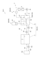
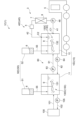
- FIG. 1 is a schematic diagram showing a schematic configuration of a machine oil regeneration system according to one embodiment.
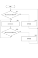
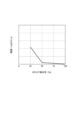
- FIG. 4 is a flowchart showing a method of using machine oil according to one embodiment. 1 is a graph showing a relationship between the RPVOT residual rate and the acid value for a machine oil that is in use or has been used. 4 is a flow chart illustrating a method of using machine oil with additional steps according to one embodiment.
- FIG. 2 is a schematic diagram showing details of the machine oil regeneration system according to the first embodiment.
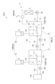
- FIG. 5 is a schematic diagram showing details of a machine oil regeneration system according to a second embodiment.
- FIG. 11 is a schematic diagram showing details of a machine oil regeneration system according to a third embodiment.
- FIG. 11 is a schematic diagram showing details of a machine oil regeneration system according to a fourth embodiment.
- FIG. 13 is a schematic diagram showing details of a machine oil regeneration system according to a fifth embodiment.
- FIG. 2 is a schematic diagram of a column according to the first embodiment.
- FIG. 1 is a schematic diagram of a column according to a second embodiment.
- FIG. 1 is a schematic diagram illustrating a machine oil regeneration system before retrofit according to one embodiment. 1 is a flowchart illustrating a method for retrofitting a machine oil regeneration unit according to one embodiment.
- expressions indicating that things are in an equal state such as “identical,””equal,” and “homogeneous,” not only indicate a state of strict equality, but also indicate a state in which there is a tolerance or a difference to the extent that the same function is obtained.
- expressions describing shapes such as a rectangular shape or a cylindrical shape do not only refer to rectangular shapes, cylindrical shapes, etc. in the strict geometric sense, but also refer to shapes that include uneven portions, chamfered portions, etc., to the extent that the same effect is obtained.
- the expressions “comprise”, “include”, or “have” a certain element are not exclusive expressions excluding the presence of other elements.
- the same components are denoted by the same reference numerals and the description thereof may be omitted.
- ⁇ Overview of Machine Oil Regeneration System 1> 1 is a schematic diagram showing a schematic configuration of a machine oil regeneration system 1 according to an embodiment of the present disclosure.
- the machine oil regeneration system 1 is configured to perform a regeneration process on machine oil 9 used by a machine oil-using device 100.
- the machine oil 9 is a lubricating oil used for smooth operation of moving parts constituting the machine oil-using device 100, or a hydraulic oil used in a hydraulic power transmission unit constituting the machine oil-using device 100.
- the machine oil-using device 100 is a turbine such as a steam turbine or a gas turbine, and the lubricating oil is mainly turbine oil supplied to the turbine rotor, etc.
- the machine oil-using device 100 is a hydraulic cylinder, and hydraulic oil is supplied to the inside of the hydraulic cylinder.
- lubricating oil and hydraulic oil are not limited to those mentioned above.
- lubricating oil may also perform other functions, such as cooling moving parts.
- Hydraulic oil may also perform the functions of lubricating and cooling power transmission parts, in addition to the power transmission function.
- Machine oil 9 deteriorates with use.
- the longer turbine oil is used, the more degraded components such as organic acids such as carboxylic acids and altered antioxidants are contained in the turbine oil, causing the color to change to brown.
- the oil performance including the lubricating performance of the turbine oil, decreases.
- a similar deterioration phenomenon is also observed in hydraulic oil.
- the machine oil regeneration system 1 of this embodiment is configured to perform a regeneration process on the machine oil 9 to prevent the partially used or used machine oil 9 from being discarded due to deterioration.
- the regeneration process includes at least one of a process of adding an additive 6 to the machine oil 9 and an adsorption process of bringing the machine oil 9 into contact with an adsorbent 8 (details will be described later).
- the machine oil regeneration system 1 includes a tank 10 for storing the machine oil 9 used in the machine oil-using device 100, an adsorption system 3 for carrying out an adsorption process in which the machine oil 9 is brought into contact with an adsorbent 8, and an additive supply device 50 for adding an additive 6 to the machine oil 9.
- Machine oil 9 flows into the tank 10 from the machine oil-using device 100 via an oil discharge passage 101.
- the machine oil 9 stored in the tank 10 is supplied to the machine oil-using device 100 via an oil supply passage 102.
- the machine oil 9 is supplied from the tank 10 to the machine oil-using device 100 by operating a supply pump 105 arranged in the oil supply passage 102.
- the number of tanks 10 may be one or more (a single tank 10 is illustrated in FIG. 1).
- the tank 10 may also be provided with an agitator 130 for agitating the machine oil 9.
- the adsorption system 3 includes a column 7 filled with an adsorbent 8, an oil circulation path 40 for circulating machine oil 9 between the column 7 and a tank 10, and an oil circulation pump 48 arranged in the oil circulation path 40.
- the oil circulation path 40 has a supply path 41 for supplying machine oil 9 from the tank 10 to the column 7, and a return path 42 for returning the machine oil 9 from the column 7 to the tank 10.
- the oil circulation pump 48 is arranged in the supply path 41.
- a filter 4 for collecting the adsorbent 8 flowing out from the column 7 may be arranged in the return path 42.
- the number of columns 7 may be one or more (a single column 7 is shown as an example in FIG. 1).
- the adsorbent 8 packed in the column 7 is silica gel, zeolite, activated alumina, activated clay, kaolin, or any combination of these.
- the silica gel may also be spherical silica gel or silica gel modified with an amino group.
- the adsorption process performed by the adsorption system 3 is outlined below.
- the machine oil 9 stored in the tank 10 flows into the column 7 via the supply path 41 by the operation of the oil circulation pump 48.
- the machine oil 9 flowing through the column 7 is subjected to an adsorption process by coming into contact with the adsorbent 8. More specifically, the deteriorated components contained in the machine oil 9 are adsorbed by the adsorbent 8, and the deteriorated components are removed from the machine oil 9.
- the machine oil 9 discharged from the column 7 returns to the tank 10 via the return path 42. In this way, the deteriorated components are removed from the machine oil 9 in the tank 10, and the degree of deterioration due to oxidation of the machine oil 9 can be reduced (details on the degree of deterioration will be described later).
- the additive supply device 50 is configured to be able to add regenerating additive 6 to the machine oil 9.
- the additive supply device 50 may be configured to directly supply additive 6 to the machine oil 9 in the tank 10, or may be configured to supply additive 6 to the machine oil 9 flowing through the return path 42.
- the additive 6 is an antioxidant, a rust inhibitor, an antifoaming agent, an antifriction agent, an extreme pressure agent, a metal deactivator, an antiemulsifier, or any combination thereof.
- the addition of additive 6 restores the oxidation stability of the machine oil 9 (oxidation stability will be described in detail later).
- the additive supply device 50 is configured to add the additive 6 to the machine oil 9 regardless of whether the adsorption process is being performed. That is, the additive supply device 50 can add the additive 6 while the machine oil 9 is passing through the column 7, and can also add the additive 6 while the machine oil 9 is not passing through the column 7.
- the inventors have discovered that in order to continuously use the machine oil 9 while avoiding significant oil deterioration, it is sufficient to subject the machine oil 9 to an adsorption process and a process for adding the additive 6 from time to time (the details of which will be described later with reference to FIG. 3).
- the adsorption system 3 can perform the adsorption process, and the additive supply device 50 can add the additive 6. This allows the machine oil 9 to be continuously used without being discarded.
- the inventors have discovered that the period during which the adsorption process is required due to an increase in the degree of deterioration due to oxidation can be made longer than the period during which the additive 6 needs to be added due to a decrease in oxidation stability.
- the period during which the adsorption process is required can be adjusted from five to six times the period during which the additive 6 is required.
- the additive supply device 50 it is also possible for the additive supply device 50 to perform a process for adding the additive 6 without performing the adsorption process in the adsorption system 3. This allows the timing of each of the adsorption process and the additive addition process to be optimized, thereby realizing a machine oil regeneration system 1 that avoids unnecessary regeneration processes for the machine oil 9.
- FIG. 2 is a flow chart showing a method for using machine oil 9 according to one embodiment of the present disclosure, and in the example shown in Fig. 2, the regeneration process of machine oil 9 is carried out only by adding additives 6 without performing adsorption process by the adsorption system 3.
- step may be abbreviated as "S”.
- a first oxidation stability determination step (S11) is executed to determine whether the oxidation stability of the machine oil 9 in use or after use is equal to or higher than a first specified level.
- the machine oil 9 is sampled from the tank 10 by an operator at regular intervals to evaluate the oxidation stability of the machine oil 9. More specifically, the oxidation stability of the machine oil 9 is evaluated through the RPVOT residual rate of the machine oil 9.
- the RPVOT residual rate indicates the ratio of the RPVOT value of the machine oil 9 in a used state to the RPVOT value of the machine oil 9 in an unused state.
- the RPVOT value is measured by an operator using various measuring instruments in accordance with the "Rotary Pressure Vessel Oxidation Stability" in JIS K 2514-3.
- the RPVOT residual rate is a value between 0% and 100%. As the degree of deterioration of the machine oil 9 due to oxidation increases, the RPVOT residual rate gradually decreases.
- the RPVOT residual rate is equal to or greater than a first threshold value, the oxidation stability is determined to be equal to or greater than a first specified level.
- the first threshold value is determined based on the relationship shown in FIG. 3.
- the first threshold value is 50% or greater, and more specifically, 70% or greater. In this way, the first threshold value is set appropriately according to the relationship between the RPVOT residual rate and the acid value.
- a first continued use step (S13) is executed to continue using the partially used or used machine oil 9. More specifically, if the supply pump 105 has stopped before the start of this flowchart, the supply pump 105 may resume operation in response to a positive determination in S11. Alternatively, if the supply pump 105 continues to operate after the start of this flowchart, a command indicating further continued operation may be input to the supply pump 105 in response to a positive determination in S11. After execution of S13, the process returns to S11.
- the machine oil-using device 100 adds additive 6 to the machine oil 9. This restores the oxidation stability.
- S53 it is determined whether the oxidation stability of the machine oil 9 is equal to or higher than a second specified level (S53). More specifically, it is determined whether the RPVOT residual rate is equal to or higher than a second threshold value.
- the second threshold value may be equal to or higher than the first threshold value described above, and in this example, is a value higher than the first threshold value. That is, the second specified level in this example is a level higher than the first specified level. If it is determined that the oxidation stability is lower than the second specified level (S53: NO), the process returns to S51.
- a second continued use step (S55) is executed to continue using the machine oil 9 to which the additive 6 has been added.
- S55 is a step similar to S13, and thereafter, the process returns to S11.
- machine oil 9 can be used continuously for a long period of time. For example, it is possible to continue using machine oil 9 for several years or more.
- oxidation stability performed in S11 and S53 may be performed using a parameter other than the RPVOT residual rate, such as the kinetic viscosity of the machine oil 9.
- the present disclosure is not limited to directly measuring the RPVOT residual rate, and oxidation stability may be evaluated by sensing a parameter that correlates with the RPVOT residual rate.
- S11 and S53 may be performed by a controller instead of an operator.
- FIG. 3 is a graph showing the relationship between RPVOT residual rate and acid value, obtained by the inventor from testing used machine oil 9 (more specifically, turbine oil).
- the acid value of machine oil 9 which is an index of the degree of deterioration due to oxidation, increases sharply.
- the process of adding additive 6 is repeated so that the RPVOT residual rate of machine oil 9 does not fall below 50%, machine oil 9 can be used continuously while suppressing the degree of deterioration of machine oil 9.
- the oxidation stability of the machine oil 9 can be restored to the second specified level or higher by executing the step (S51) of adding the additive 6. This allows the degree of deterioration of the machine oil 9 due to oxidation to be maintained at the initial level, and the machine oil 9 can be used continuously without being discarded.
- Fig. 4 is a flow chart showing a method of using the machine oil 9 including additional steps according to an embodiment of the present disclosure.
- the same steps as those in Fig. 2 are given the same step numbers, and their explanations are omitted or simplified below.
- S21 to S29 are executed, and these steps are related to the adsorption process.
- S21 is executed when a negative determination is made in S11.
- One example of the degree of deterioration due to oxidation is the acid value. If the acid value is below the first acid value threshold, the degree of deterioration is determined to be below the first degree of deterioration. Conversely, if the acid value is equal to or greater than the first acid value threshold, the degree of deterioration is determined to be equal to or greater than the first degree of deterioration.
- One example of the first acid value threshold is 0.1 mg KOH/g. The acid value is measured by an operator using various measuring instruments in accordance with JIS K2501:2003.
- an adsorption step (S23) is executed to subject the machine oil 9 to an adsorption process. More specifically, the oil circulation pump 48 is operated to cause the machine oil 9 to flow into the column 7, and the adsorption process is executed.
- the second degree determines whether the deterioration degree of the machine oil 9 falls below the second degree (S25). More specifically, it is determined whether the acid value falls below the second acid value threshold.
- the second acid value threshold may be any value equal to or less than the first acid value threshold, and in this example, is the same value as the first acid value threshold. If it is determined that the deterioration degree falls below the second degree (S25: YES), the above-mentioned step (S51) of adding the additive 6 to the machine oil 9 is executed.
- N the number of consecutive executions of the adsorption process
- the present disclosure is not limited to the evaluation of the degree of deterioration performed in S21 and S25 being performed through the acid value.
- the degree of deterioration may be evaluated by sensing a parameter that correlates with the acid value.
- S21 and S25 may be performed by a controller instead of an operator.
- a step (S51) of adding additive 6 is executed.
- the addition step (S51) is executed on the machine oil 9 whose degree of deterioration has been suppressed, so that it is possible to avoid a problem in which the degree of deterioration due to oxidation does not return to normal even if the addition step is executed.
- the step of adding the additive 6 (S51) is executed. If the degree of deterioration of the machine oil 9 is high, the adsorption process (S23) is executed before the addition step (S51), so that the degree of deterioration due to oxidation of the machine oil 9 can be reliably maintained at the initial level.
- Figure 5A shows a schematic diagram of a machine oil regeneration system 1A(1) according to a first embodiment
- Figure 5B shows a machine oil regeneration system 1B(1) according to a second embodiment
- Figure 5C shows a machine oil regeneration system 1C(1) according to a third embodiment
- Figure 5D shows a machine oil regeneration system 1D(1) according to a fourth embodiment
- Figure 5E shows a machine oil regeneration system 1E(1) according to a fifth embodiment.
- the machine oil regeneration system 1A to 1D (1) includes a tank 10A to 10D (10), an additive supply device 50A to 50D (50), and an oil circulation path 40A to 40D (40).
- the additive supply device 50A-50D (50) is configured to supply additive 6 to the inside of the tank 10A-10D (10) via an additive supply path 55 that is different from the oil circulation path 40A-40D (40).
- the additive supply path 55 may be a pipe that connects to the tank 10A-10D, or it may be a space (area) through which the additive 6 passes when it falls.
- the additive 6 flows into the tank 10A-10D at a position away from both the connection position C1 between the supply path 41 and the tank 10A-10D and the connection position C2 between the return path 42 and the tank 10A-10D.
- the process of adding additive 6 is carried out at a location separate from the oil circulation path 40 where the adsorption process is carried out. This makes it easier to carry out the process of adding additive 6 separately from the adsorption process.
- the tanks 10A to 10C include a first tank 11 and a second tank 12.
- the first tank 11 is connected to each of the oil discharge passage 101 and the oil supply passage 102.
- the first tank 11 is configured to store the machine oil 9 discharged from the machine oil-using device 100, and is configured to release the machine oil 9 toward the machine oil-using device 100.
- the second tank 12 is arranged separately from the first tank 11.
- An oil circulation path 40 is connected to the second tank 12. That is, the machine oil 9 stored in the second tank 12 is supplied to the column 7 via a supply path 41, and the machine oil 9 flowing out from the column 7 is returned to the column 7 via a return path 42.
- the machine oil regeneration systems 1A to 1C include a connection flow path unit 60 that connects the first tank 11 and the second tank 12.
- the connection flow path unit 60 includes a first oil flow path 61 for guiding the machine oil 9 from the first tank 11 to the second tank 12, a first pump 63 arranged in the first oil flow path 61, a second oil flow path 62 for guiding the machine oil 9 from the second tank 12 to the first tank 11, and a second pump 64 arranged in the second oil flow path 62.
- the first pump 63 is driven and the machine oil 9 flows from the first tank 11 to the second tank 12.
- the regenerated machine oil 9 in the second tank 12 is returned to the first tank 11 by driving the second pump 64.
- the additive supplying devices 50A-50C are configured to supply additive 6 to at least the second tank 12. More specifically, the additive supplying devices 50A-50C include a second additive supplying device 52 for supplying additive 6 to the second tank 12. In addition, the agitators 130A-130C (130) include a second agitator 132 for agitating the machine oil 9 stored in the second tank 12.
- the regeneration process of the machine oil 9 is performed in the second tank 12, which is different from the first tank 11, which is required to appropriately release the machine oil 9 toward the machine oil-using device 100.
- the machine oil 9 is regenerated in a batch manner during regular inspection of the machine oil-using device 100, it is possible to regenerate the machine oil 9 in the second tank 12, which is different from the first tank 11.
- the machine oil 9 in an embodiment in which the machine oil 9 is regenerated in a continuous manner while the machine oil-using device 100 is in operation, the machine oil 9 can be regenerated in the second tank 12, which is different from the first tank 11, so that the machine oil 9 can be regenerated without impeding the flow of the machine oil 9 between the first tank 11 and the machine oil 9.
- the additive supplying devices 50B, 50C further include a first additive supplying device 51 for supplying additive 6 to the first tank 11, in addition to the second additive supplying device 52 described above.
- the agitators 130B, 130C (130) include a first agitator 131 for agitating the machine oil 9 stored in the first tank 11.
- the second tank 12 of the tank 10C is connected to the first tank 11 via a connection flow path unit 60 while mounted on the transport vehicle 5.
- the connection flow path unit 60 is arranged so as to be removable from the first tank 11 and the second tank 12.
- the adsorption system 3 may be mounted on the transport vehicle 5 together with the second tank 12, or may be connected to the second tank 12 while installed on land.
- connection flow path unit 60 only when regeneration of the machine oil 9 is required, is it necessary to move the transport vehicle 5 carrying the second tank 12 close to the first tank 11 and connect the second tank 12 to the first tank 11 via the connection flow path unit 60.
- This allows the second tank 12 and the connection flow path unit 60 to be used in another machine oil regeneration system 1 or stored in a dedicated area when regeneration is not required. This allows for more flexible use of the second tank 12 and the connection flow path unit 60.
- the tank 10D of the machine oil regeneration system 1D includes a first tank 11 but does not include a second tank 12 (see Figures 5A to 5C).
- an oil circulation path 40D is connected to the first tank 11, and the additive supply device 50D includes a first additive supply device 51 but does not include a second additive supply device 52 (see Figures 5A to 5C).
- the tank 10E(10) of the machine oil regeneration system 1E(1) includes a first tank 11, but does not include a second tank 12 (see FIGS. 5A to 5C). Furthermore, the oil circulation path 40E(40) that constitutes the machine oil regeneration system 1E(1) further includes a bypass path 43 that is connected to the supply path 41 and the return path 42 so as to bypass the column 7.
- a valve 45 is further disposed in the oil circulation path 40E.
- the valve 45 is configured so that the machine oil 9 flowing through the supply path 41 selectively flows to either the column 7 or the bypass path 43.
- the valve 45 is a three-way valve disposed at a position where the bypass path 43 and the supply path 41 are connected.
- the valve 45 may be an on-off valve disposed in at least one of the bypass path 43 or the supply path 41.
- the oil circulation pump 48 illustrated in FIG. 5E is disposed in the supply line 41 upstream of the valve 45.
- the present disclosure is not limited to this, and the oil circulation pump 48 may be composed of a first oil circulation pump disposed between the valve 45 and the column 7, and a second oil circulation pump disposed in the bypass line 43.
- the additive supply device 50E illustrated in FIG. 5E is disposed in the return path 42 downstream of the position where the bypass path 43 and the return path 42 are connected.
- the valve 45 is switched so that the machine oil 9 does not flow into the bypass path 43.
- the additive 6 is added from the additive supply device 50E to the machine oil 9 flowing through the return path 42 via the bypass path 43 by the drive of the oil circulation pump 48.
- the valve 45 is switched so that the machine oil 9 flows into the column 7.
- the machine oil 9 flowing through the supply path 41 flows in order through the supply path 41, the column 7, and the return path 42 as the oil circulation pump 48 is driven. At this time, the additive supply device 50E does not operate.
- the above configuration allows selective addition or adsorption of additive 6 to be performed on machine oil 9 flowing through oil circulation path 40.
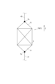
- Fig. 6A is a schematic diagram of column 7A (7) according to the first embodiment
- Fig. 6B is a schematic diagram of column 7B (7) according to the second embodiment.
- Columns 7A and 7B may be applied to any of the machine oil regeneration systems 1A to 1E (1) shown in Figs. 5A to 5E.
- a plurality of columns 7A (7) are arranged in parallel to one another on the oil circulation path 40F (40). More specifically, the oil circulation path 40F has a plurality of column connection paths 47 in which the plurality of columns 7A are respectively arranged. Each of the plurality of column connection paths 47 arranged in parallel to one another is connected to a supply path 41 and a return path 42. A plurality of flow adjustment valves 46 may be arranged in each of the plurality of column connection paths 47. Furthermore, a plurality of on-off valves 44 may be further arranged in each of the plurality of column connection paths 47. may be arranged.
- multiple columns 7A By arranging multiple columns 7A in parallel with each other, it is possible to suppress a decrease in flow rate due to pressure loss of the machine oil 9 in the oil circulation path 40F, thereby shortening the time required for the adsorption process. Furthermore, by arranging multiple flow control valves 95 in each of the multiple column connection paths 47, it is possible to evenly flow the machine oil 9 to the multiple columns 7A, so that the adsorption process can be performed evenly in the multiple columns 7A.
- At least one of the multiple columns 7A shown in FIG. 6A is configured to be replaceable with a new column 7A filled with unused adsorbent 8.
- the on-off valve 44 corresponding to a column 7A that is due for replacement among the multiple columns 7A is closed, and that column 7A is replaced with a new column 7A.
- machine oil 9 may be poured into the remaining columns 7A that have not yet reached the time for replacement, and an adsorption process may be performed. With the above configuration, the adsorption capacity can be restored by replacing the column 7A, so that the machine oil 9 can be used continuously for a longer period of time.
- a heater 77 for adjusting the temperature of the machine oil 9 flowing in the column 7A may be further disposed in the oil circulation path 40F.
- the heater 77 is disposed upstream of the connection position between the supply path 41 and the multiple column connection paths 47.
- column 7B (7) includes one end 71 where inlet 7a for machine oil 9 is formed, and the other end 72 where outlet 7b for machine oil 9 is formed.
- one end 71 has a shape in which the inner diameter becomes smaller the further upstream
- the other end 72 has a shape in which the inner diameter becomes smaller the further downstream.
- FIG. 7 is a schematic diagram showing a machine oil regeneration system 1F before modification according to an embodiment of the present disclosure.
- FIG. 8 is a flow chart showing a method of adding a machine oil regeneration unit 2 according to an embodiment of the present disclosure.
- the machine oil regeneration unit 2 (see FIG. 1) is a unit including an adsorption system 3 and an additive supply device 50.
- the pre-modification machine oil regeneration system 1F includes a tank 10, but does not include a machine oil regeneration unit 2 (see FIG. 1).
- a column installation step S101 is performed to install a column 7 filled with an adsorbent 8.
- an oil circulation path installation step (S103) is performed to install the oil circulation path 40.
- S103 at least the supply path 41 and the return path 42 are installed.
- a bypass path 43 may also be installed.
- a valve 45 is also arranged.
- a pump installation step (S105) for installing an oil circulation pump 48 in the oil circulation path 40, an additive supply device installation step (S107) for installing an additive supply device 50, and an agitator installation step (S109) for installing an agitator 130 in the tank 10 are carried out in sequence. This completes the installation of the machine oil regeneration unit 2 and the machine oil regeneration system 1 (see FIG. 1).
- S101 to S109 are performed by an operator, a robot arm operated by an operator, or a combination of these.
- the order in which S101 to S109 are performed may be changed as appropriate.
- a step of installing a heater 77 in the supply path 41 may be additionally performed.
- the method of adding the machine oil regeneration unit 2 may further include a step of adding a second tank 12 and a step of adding a connection flow path unit 60.
- the "controller” in the above description is configured by a computer, and includes a processor, a memory (storage medium), and an external communication interface.
- the processor is a CPU, a GPU, an MPU, a DSP, or a combination of these.
- the memory is configured to store various data temporarily or non-temporarily, and is realized by at least one of a RAM, a ROM, and a flash memory, for example.
- the processor executes various control processes according to the instructions of the program loaded into the memory.
- a method of using the machine oil (9) includes: 1. A method for using a machine oil for at least one of lubrication and power transmission, comprising: A first oxidation stability determination step (S11) of determining whether the oxidation stability of the machine oil in use or after use is equal to or higher than a first specified level; If it is determined that the oxidation stability is equal to or higher than the first specified level, a first continuous use step (S13) of continuing to use the partially used or used machine oil; If it is determined that the oxidation stability is below the first specified level, an additive (6) for regeneration is added to the machine oil so that the oxidation stability is equal to or higher than a second specified level (S51); and a second continuous use step (S55) of continuously using the machine oil to which the additive has been added.
- the inventors have discovered that if an additive is added to the machine oil from time to time so that the oxidation stability of the machine oil is maintained above a certain level, the machine oil can be used continuously while maintaining its oil performance.
- the addition step can be performed to restore the oxidation stability of the machine oil to a second specified level or higher. This allows the degree of deterioration of the machine oil due to oxidation to be maintained at the initial level, and the machine oil can be used continuously without being discarded.
- the method for using the machine oil described in 1) above includes the steps of:
- the method further includes a first deterioration progress determination step (S21) of determining whether a deterioration progress degree due to oxidation of the machine oil in use or after use is below a first deterioration progress degree, prior to the adding step;
- the adding step is executed when it is determined in the first deterioration progress determination step that the deterioration progress degree falls below the first deterioration progress degree.
- the addition step is performed on machine oil whose degree of deterioration has been suppressed, so that it is possible to avoid a problem in which the degree of deterioration due to oxidation does not return to normal even when the addition step is performed.
- the method for using the machine oil described in 2) above includes the steps of:
- the method further includes an adsorption step (S23) of carrying out an adsorption treatment of bringing the machine oil into contact with an adsorbent (8) before the addition step when the deterioration degree is determined to be equal to or greater than the first deterioration degree in the first deterioration progress determination step,
- the adding step adds the additive to the machine oil whose deterioration degree has fallen below a second deterioration degree as a result of the adsorption treatment.
- the adsorption process is performed before the addition step. This makes it possible to reliably maintain the deterioration of the machine oil due to oxidation at its initial level.
- a method for using the machine oil described in 3) above comprising: The method further includes an adsorbent replacement step (S29) of replacing the adsorbent used in the adsorption process if the degree of deterioration does not fall below the second degree of deterioration even after the adsorption process is repeated a specified number of times.
- S29 adsorbent replacement step
- the machine oil regeneration system (1) is A tank (10) for storing used or partially used machine oil (9) for at least one of lubrication and power transmission;
- An adsorption system comprising: A column (7) packed with an adsorbent (8); an oil circulation path (40) for circulating the machine oil between the column and the tank; an oil circulation pump (48) disposed in the oil circulation path; an adsorption system (3) configured to perform an adsorption process in which the machine oil is brought into contact with the adsorbent by driving the oil circulation pump; and an additive supply device (50) configured to be able to add an additive for regeneration to the machine oil regardless of whether the adsorption treatment is being performed or not.
- the inventors have discovered that in order to use machine oil continuously while avoiding significant oil deterioration, it is sufficient to subject the machine oil to an adsorption process and a process of adding additives from time to time.
- the adsorption process and the process of adding additives can be performed on the machine oil, so that the machine oil can be used continuously without being discarded.
- the period during which the adsorption process is required as the oxidation progresses can be made longer than the period during which the addition of additives is required as the oxidation stability decreases.
- the additive supply device is configured to supply the additive to the interior of the tank via an additive supply path (55) that is different from the oil circulation path.
- the process of adding the additive is carried out at a location separate from the oil circulation path where the adsorption process is carried out. This makes it easier to carry out the process of adding the additive separately from the adsorption process.
- the tank is A first tank (11) for storing the machine oil discharged from an oil-using device (machine oil-using device 100) that uses the machine oil; a second tank (12) that is arranged separately from the first tank and to which the oil circulation path is connected;
- the machine oil regeneration system further includes a connection flow passage unit (60) for connecting the first tank and the second tank and for allowing the machine oil to flow;
- the additive supply device is configured to supply the additive to at least the second tank.
- the regeneration process of the machine oil is carried out in a second tank different from the first tank that is required to appropriately release the machine oil toward the oil-using device. This makes it easier to carry out the regeneration process.
- the machine oil is regenerated in a batch manner during regular inspection of the oil-using device, it is possible to regenerate the machine oil in a second tank different from the first tank.
- the machine oil can be regenerated in a second tank different from the first tank, so that the machine oil can be regenerated without impeding the flow of the machine oil between the first tank and the machine oil.
- the additive supply device includes: a first additive supply device (51) configured to supply the additive to the first tank; and a second additive supply (52) configured to supply the additive to the second tank.
- the configuration of 8) above allows the process of adding additives to both the first tank and the second tank, so oil performance can be maintained more reliably.
- the machine oil regeneration system according to 7) or 8) above,
- the second tank is connected to the first tank via the connection passage unit while being mounted on the transport vehicle (5).
- the transport vehicle carrying the second tank is moved to the vicinity of the first tank and the second tank is connected to the first tank via the connection flow path unit.
- This allows the second tank and the connection flow path unit to be used in another machine oil regeneration system or stored in a dedicated area when regeneration is not required. This allows for more flexible use of the second tank and the connection flow path unit.
- the tank includes a first tank (11) for storing the machine oil discharged from an oil-using device that uses the machine oil, the additive supply device is configured to supply the additive to the first tank;
- the oil circulation path is connected to the first tank.
- the configuration of 10) above allows the machine oil regeneration process to be carried out without installing a second tank separate from the first tank, making it possible to make the machine oil regeneration system more compact.
- the oil circulation path is A supply line (41) for supplying the machine oil from the tank to the column; a return line (42) for returning the machine oil from the column to the tank; a bypass line (43) connected to the supply line and the return line so as to bypass the column; having the adsorption system further includes a valve (45) for selectively allowing the machine oil flowing through the supply line to flow to either the column or the bypass line;
- the additive supply device is disposed in the return passage downstream of a location where the bypass passage and the return passage join.
- the configuration of 11) above allows additives to be selectively added or adsorbed to the machine oil flowing through the oil circulation path.
- the machine oil regeneration system according to any one of 5) to 11) above, A plurality of the columns are arranged in parallel on the oil circulation path.
- the configuration of 12) above can suppress the decrease in flow rate due to pressure loss of the machine oil in the oil circulation path, thereby shortening the time required for the adsorption process.
- the machine oil regeneration system described in 12) above has a plurality of columns arranged therein and a plurality of column connection paths (47) arranged in parallel to each other,
- the adsorption system further includes a plurality of flow regulation valves (46) disposed in the plurality of column connecting paths, respectively.
- At least one of the plurality of columns is configured to be replaceable.
- the adsorption capacity can be restored by replacing the column, so machine oil can be used continuously for a longer period of time.
- the machine oil regeneration system according to any one of 5) to 13) above,
- the column comprises: One end (71) in which the machine oil inlet (7a) is formed; and the other end (72) in which the machine oil outlet (7b) is formed, In the flow direction of the machine oil in the column,
- the one end has a shape in which the inner diameter becomes smaller toward the upstream side, and
- the other end has a shape in which the inner diameter becomes smaller toward the downstream side.
- the configuration of 15) above can prevent machine oil from stagnating near the inlet or outlet, allowing for more effective adsorption of the machine oil.
- the machine oil regeneration system according to any one of 5) to 14) above, The apparatus further includes a heater (77) configured to adjust the temperature of the machine oil flowing through the column.
- the configuration of 16) above allows the temperature of the machine oil to be adjusted to a temperature suitable for the adsorption process, improving the adsorption efficiency in the column.
- a method for adding a machine oil regeneration unit (2) comprising: A method for regenerating a used or partially used machine oil (9) for at least one of lubrication and power transmission stored in a tank (10), comprising the steps of: a column installation step (S101) of installing a column (7) filled with an adsorbent (8); an oil circulation path installation step (S103) of installing an oil circulation path (40) for circulating the machine oil between the column and the tank; a pump installation step (S105) of installing an oil circulation pump (48) in the oil circulation path; and an additive supply device installation step (S107) of installing an additive supply device (50) configured to be able to add an additive for regeneration to the machine oil.
- Machine oil regeneration system 2 Machine oil regeneration unit 3: Adsorption system 4: Filter 5: Transport vehicle 6: Additive 7: Column 7a: Inlet 7b: Outlet 8: Adsorbent 9: Machine oil 10: Tank 11: First tank 12: Second tank 40: Oil circulation path 41: Supply path 42: Return path 43: Bypass path 44: Opening/closing valve 45: Valve 46: Flow adjustment valve 47: Column connection path 48: Oil circulation pump 50: Additive supply device 51: First additive supply device 52: Second additive supply device 55: Additive supply path 60: Connection flow path unit 61: First oil flow path 62: Second oil flow path 63: First pump 64: Second pump 71: One end 72: Other end 77: Heater 95: Flow adjustment valve 100: Machine oil using device (oil using device) 101: Oil discharge passage 102: Oil supply passage 105: Supply pump 130: Agitator 131: First agitator 132: Second agitator C1: Connection position C2: Connection position Z: Arrow
Landscapes
- Chemical & Material Sciences (AREA)
- Organic Chemistry (AREA)
- Chemical Kinetics & Catalysis (AREA)
- Analytical Chemistry (AREA)
- Inorganic Chemistry (AREA)
- Oil, Petroleum & Natural Gas (AREA)
- General Chemical & Material Sciences (AREA)
- Engineering & Computer Science (AREA)
- Combustion & Propulsion (AREA)
- Life Sciences & Earth Sciences (AREA)
- Dispersion Chemistry (AREA)
- Geochemistry & Mineralogy (AREA)
- Solid-Sorbent Or Filter-Aiding Compositions (AREA)
- Lubricants (AREA)
- Production Of Liquid Hydrocarbon Mixture For Refining Petroleum (AREA)
- Fluid-Pressure Circuits (AREA)
Abstract
潤滑または動力伝達の少なくとも一方に用いる機械油の使用方法は、使用途中または使用済みの機械油の酸化安定性が第1規定水準以上であるかを判定する第1酸化安定判定ステップと、酸化安定性が第1規定水準以上であると判定された場合、使用途中または使用済みの機械油を引き続き使用する第1継続使用ステップと、酸化安定性が第1規定水準を下回ると判定された場合、酸化安定性が第2規定水準以上になるように機械油に再生用の添加剤を添加する添加ステップと、添加剤が添加された機械油を引き続き使用する第2継続使用ステップとを備える。
Description
本開示は、機械油の使用方法、機械油再生システム、および、機械油再生ユニットの追設方法に関する。
本願は、2023年6月30日に日本国特許庁に出願された特願2023-107817号に基づき優先権を主張し、その内容をここに援用する。
本願は、2023年6月30日に日本国特許庁に出願された特願2023-107817号に基づき優先権を主張し、その内容をここに援用する。
特許文献1には、使用済みの絶縁油を再生する方法が記載されている。具体的には、漆喰、珪藻土、ベントナイト、または、マリンシルトのいずれか1つ以上を有する吸着剤を使用済みの絶縁油に接触させて絶縁油中の劣化成分を吸着剤に吸着させた後、絶縁油から吸着剤を取り除き、絶縁油に酸化防止剤を添加することにより、再生した絶縁油が得られる。
特許文献1の方法によれば、絶縁油の再生が可能であるが、潤滑または動力伝達の少なくとも一方に用いる機械油の再生が可能であるかどうかはわからない。
本開示は、機械油を廃棄することなく継続的に使用することができる機械油の使用方法、機械油再生システム、および、機械油再生ユニットの追設方法を提供することである。
本開示の少なくとも一実施形態に係る機械油の使用方法は、
潤滑または動力伝達の少なくとも一方に用いる機械油の使用方法であって、
使用途中または使用済みの前記機械油の酸化安定性が第1規定水準以上であるかを判定する第1酸化安定判定ステップと、
前記酸化安定性が前記第1規定水準以上であると判定された場合、使用途中または使用済みの前記機械油を引き続き使用する第1継続使用ステップと、
前記酸化安定性が前記第1規定水準を下回ると判定された場合、前記酸化安定性が第2規定水準以上になるように前記機械油に再生用の添加剤を添加する添加ステップと、
前記添加剤が添加された前記機械油を引き続き使用する第2継続使用ステップと
を備える。
潤滑または動力伝達の少なくとも一方に用いる機械油の使用方法であって、
使用途中または使用済みの前記機械油の酸化安定性が第1規定水準以上であるかを判定する第1酸化安定判定ステップと、
前記酸化安定性が前記第1規定水準以上であると判定された場合、使用途中または使用済みの前記機械油を引き続き使用する第1継続使用ステップと、
前記酸化安定性が前記第1規定水準を下回ると判定された場合、前記酸化安定性が第2規定水準以上になるように前記機械油に再生用の添加剤を添加する添加ステップと、
前記添加剤が添加された前記機械油を引き続き使用する第2継続使用ステップと
を備える。
本開示の少なくとも一実施形態に係る機械油再生システムは、
潤滑または動力伝達の少なくとも一方に用いる使用途中または使用済の機械油を貯留するタンクと、
吸着系統であって、
吸着剤を充填したカラムと、
前記カラムと前記タンクとの間で前記機械油が循環するための油循環路と、
前記油循環路に配置される油循環ポンプと、
を含み、前記油循環ポンプの駆動によって、前記機械油を前記吸着剤に接触させる吸着処理を実行するように構成された吸着系統と、
前記吸着処理が実行されているか否かに関わらず、前記機械油に再生用の添加剤を添加可能に構成される添加剤供給装置と
を備える。
潤滑または動力伝達の少なくとも一方に用いる使用途中または使用済の機械油を貯留するタンクと、
吸着系統であって、
吸着剤を充填したカラムと、
前記カラムと前記タンクとの間で前記機械油が循環するための油循環路と、
前記油循環路に配置される油循環ポンプと、
を含み、前記油循環ポンプの駆動によって、前記機械油を前記吸着剤に接触させる吸着処理を実行するように構成された吸着系統と、
前記吸着処理が実行されているか否かに関わらず、前記機械油に再生用の添加剤を添加可能に構成される添加剤供給装置と
を備える。
本開示の少なくとも一実施形態に係る機械油再生ユニットの追設方法は、
タンク内に貯留される潤滑または動力伝達の少なくとも一方に用いる使用途中または使用済の機械油を再生するための機械油再生ユニットの追設方法であって、
吸着剤を充填したカラムを設置するカラム設置ステップと、
前記カラムと前記タンクとの間で前記機械油が循環するための油循環路を設置する油循環路設置ステップと、
前記油循環路に油循環ポンプを設置するポンプ設置ステップと、
前記機械油に再生用の添加剤を添加可能に構成された添加剤供給装置を設置する添加剤供給装置設置ステップと
を備える。
タンク内に貯留される潤滑または動力伝達の少なくとも一方に用いる使用途中または使用済の機械油を再生するための機械油再生ユニットの追設方法であって、
吸着剤を充填したカラムを設置するカラム設置ステップと、
前記カラムと前記タンクとの間で前記機械油が循環するための油循環路を設置する油循環路設置ステップと、
前記油循環路に油循環ポンプを設置するポンプ設置ステップと、
前記機械油に再生用の添加剤を添加可能に構成された添加剤供給装置を設置する添加剤供給装置設置ステップと
を備える。
本開示によれば、機械油を廃棄することなく継続的に使用することができる機械油の使用方法、機械油再生システム、および、機械油再生ユニットの追設方法を提供できる。
以下、添付図面を参照して本開示の幾つかの実施形態について説明する。ただし、実施形態として記載されている又は図面に示されている構成部品の寸法、材質、形状、その相対的配置等は、本開示の範囲をこれに限定する趣旨ではなく、単なる説明例にすぎない。
例えば、「ある方向に」、「ある方向に沿って」、「平行」、「直交」、「中心」、「同心」或いは「同軸」等の相対的或いは絶対的な配置を表す表現は、厳密にそのような配置を表すのみならず、公差、若しくは、同じ機能が得られる程度の角度や距離をもって相対的に変位している状態も表すものとする。
例えば、「同一」、「等しい」及び「均質」等の物事が等しい状態であることを表す表現は、厳密に等しい状態を表すのみならず、公差、若しくは、同じ機能が得られる程度の差が存在している状態も表すものとする。
例えば、四角形状や円筒形状等の形状を表す表現は、幾何学的に厳密な意味での四角形状や円筒形状等の形状を表すのみならず、同じ効果が得られる範囲で、凹凸部や面取り部等を含む形状も表すものとする。
一方、一の構成要素を「備える」、「含む」、又は、「有する」という表現は、他の構成要素の存在を除外する排他的な表現ではない。
なお、同様の構成については同じ符号を付し説明を省略することがある。
例えば、「ある方向に」、「ある方向に沿って」、「平行」、「直交」、「中心」、「同心」或いは「同軸」等の相対的或いは絶対的な配置を表す表現は、厳密にそのような配置を表すのみならず、公差、若しくは、同じ機能が得られる程度の角度や距離をもって相対的に変位している状態も表すものとする。
例えば、「同一」、「等しい」及び「均質」等の物事が等しい状態であることを表す表現は、厳密に等しい状態を表すのみならず、公差、若しくは、同じ機能が得られる程度の差が存在している状態も表すものとする。
例えば、四角形状や円筒形状等の形状を表す表現は、幾何学的に厳密な意味での四角形状や円筒形状等の形状を表すのみならず、同じ効果が得られる範囲で、凹凸部や面取り部等を含む形状も表すものとする。
一方、一の構成要素を「備える」、「含む」、又は、「有する」という表現は、他の構成要素の存在を除外する排他的な表現ではない。
なお、同様の構成については同じ符号を付し説明を省略することがある。
<機械油再生システム1の概要>
図1は、本開示の一実施形態に係る機械油再生システム1の概略的な構成を示す概略図である。機械油再生システム1は、機械油使用装置100によって使用された機械油9に再生処理を施すように構成される。機械油9は、機械油使用装置100を構成する可動部品が円滑に動作するために用いられる潤滑油、または、機械油使用装置100を構成する油圧式の動力伝達ユニットに用いられる油圧作動油である。
図1は、本開示の一実施形態に係る機械油再生システム1の概略的な構成を示す概略図である。機械油再生システム1は、機械油使用装置100によって使用された機械油9に再生処理を施すように構成される。機械油9は、機械油使用装置100を構成する可動部品が円滑に動作するために用いられる潤滑油、または、機械油使用装置100を構成する油圧式の動力伝達ユニットに用いられる油圧作動油である。
一例として、機械油使用装置100は、蒸気タービンまたはガスタービンといったタービンであり、潤滑油は主としてタービンロータなどに供給されるタービン油である。他の例として、機械油使用装置100は油圧シリンダであり、油圧作動油は、油圧シリンダの内部に供給されるようになっている。
なお、潤滑油および油圧作動油は上記の用途に限定されない。また、潤滑油は、可動部品の潤滑機能の他に、可動部品の冷却機能など他の機能を併せて担ってもよい。油圧作動油も、動力伝達機能の他に、動力伝達部品の潤滑機能および冷却機能などを併せて担ってもよい。
機械油9は使用されるに従い劣化する。例えば、タービン油の使用期間が長くなるほど、カルボン酸等の有機酸のような劣化成分と酸化防止剤の変質物とがタービン油に含まれるようになり、色が茶褐色に変色する。この場合、タービン油の潤滑性能をはじめとする油性能は低下する。また、油圧作動油においても、同様の劣化現象が確認される。本実施形態の機械油再生システム1は、使用途中または使用済みの機械油9が劣化を理由として廃棄されるのを避けるべく、機械油9に再生処理を施すように構成されている。再生処理には、機械油9に添加剤6を添加する処理、または、機械油9を吸着剤8に接触させる吸着処理の少なくとも一方が含まれる(詳細は後述)。
引き続き図1を参照して、機械油再生システム1の構成を概説する。機械油再生システム1は、機械油使用装置100で使用される機械油9を貯留するためのタンク10と、機械油9を吸着剤8に接触させる吸着処理を実行するための吸着系統3と、機械油9に添加剤6を添加するための添加剤供給装置50とを備える。
タンク10には、機械油使用装置100から油排出路101を経由して機械油9が流入するようになっている。タンク10に貯留される機械油9は、油供給路102を経由して機械油使用装置100に供給されるようになっている。本例では、油供給路102に配置された供給ポンプ105が作動することで、タンク10から機械油使用装置100に機械油9は供給される。タンク10の個数は単数であってもよいし、複数であってもよい(図1では、単数のタンク10が例示されている。)。また、タンク10には、機械油9を攪拌するための撹拌機130が設けられてもよい。
吸着系統3は、吸着剤8を充填したカラム7と、カラム7およびタンク10の間で機械油9が循環するための油循環路40と、油循環路40に配置される油循環ポンプ48とを含む。油循環路40は、タンク10からカラム7に機械油9を供給するための供給路41と、カラム7からタンク10に機械油9を戻すための戻し路42とを有する。油循環ポンプ48は供給路41に配置されている。戻し路42には、カラム7から流出する吸着剤8を捕集するためのフィルタ4が配置されてもよい。
カラム7の個数は単数であってもよいし、複数であってもよい(図1では単数のカラム7が例示されている。)。カラム7に充填される吸着剤8は、シリカゲル、ゼオライト、活性アルミナ、活性白土、カオリン、または、これらの任意の組み合わせである。また、シリカゲルは、球状シリカゲルやアミノ基で修飾したシリカゲルであってもよい。
吸着系統3が実行する吸着処理の概要は、以下の通りである。タンク10に貯留される機械油9は、油循環ポンプ48の作動によって、供給路41を経由してカラム7に流入する。カラム7内を流れる機械油9は、吸着剤8と接触することで、吸着処理を施される。より具体的には、機械油9に含まれる劣化成分が吸着剤8に吸着されて、機械油9から劣化成分が除去される。カラム7から排出される機械油9は、戻し路42を経由してタンク10に戻る。このようにして、タンク10内の機械油9から劣化成分が除去され、機械油9の酸化による劣化進行度を低減できる(劣化進行度の詳細は後述)。
添加剤供給装置50は、機械油9に再生用の添加剤6を添加可能に構成されている。添加剤供給装置50は、タンク10内の機械油9に添加剤6を直接的に供給するように構成されてもよいし、戻し路42を流れる機械油9に添加剤6を供給するように構成されてもよい。添加剤6は、酸化防止剤、さび止め剤、消泡剤、摩擦防止剤、極圧剤、金属不活性化剤、抗乳化剤、またはこれらの任意の組み合わせである。添加剤6の添加によって、機械油9の酸化安定性は回復する(酸化安定性の詳細は後述)。
添加剤供給装置50は、吸着処理が実行されているか否かに関わらず、機械油9に添加剤6を添加するように構成されている。即ち、添加剤供給装置50は、機械油9がカラム7を通過している間に添加剤6を添加することも可能であるし、機械油9がカラム7を通過していない間に添加剤6を添加することも可能である。
発明者は、著しい油劣化を避けつつ機械油9を継続的に使用するためには、時々に応じて、吸着処理および添加剤6を添加する処理を機械油9に施せばよいことを発見した(その詳細は図3を用いて後述する)。この点、上記構成によれば、吸着系統3が吸着処理を実行でき、添加剤供給装置50が添加剤6を添加できる。これにより、機械油9を廃棄することなく継続的に使用することができる。さらに、酸化による劣化進行度の増大に伴って吸着処理が必要になる周期を、酸化安定性の低下に伴って添加剤6の添加が必要になる周期よりも長くできることを発明者は発見した。例えば、機械油9がタービン油である場合、吸着処理が必要になる周期は、添加剤6が必要になる周期の5倍の値から6倍の値に調整することができる。この点、上記構成によれば、吸着系統3の吸着処理を実行することなく、添加剤供給装置50は添加剤6を添加する処理を実行することも可能になる。これにより、吸着処理と添加剤添加処理の各々の実行タイミングの適正化を図ることができ、機械油9の不必要な再生処理を回避した機械油再生システム1が実現される。
<機械油9の使用方法の概要>
図2を参照し、機械油再生システム1を利用して機械油9を継続的に使用する方法を概説する。図2は、本開示の一実施形態に係る機械油9の使用方法を示すフローチャートであり、同図の例では、吸着系統3による吸着処理を行わず、添加剤6の添加のみによって機械油9の再生処理が実行される。以下の説明では、「ステップ」を「S」と略記する場合がある。
図2を参照し、機械油再生システム1を利用して機械油9を継続的に使用する方法を概説する。図2は、本開示の一実施形態に係る機械油9の使用方法を示すフローチャートであり、同図の例では、吸着系統3による吸着処理を行わず、添加剤6の添加のみによって機械油9の再生処理が実行される。以下の説明では、「ステップ」を「S」と略記する場合がある。
はじめに、使用途中または使用済みの機械油9の酸化安定性が第1規定水準以上であるかを判定する第1酸化安定判定ステップ(S11)が実行される。例えば、一定期間ごとにタンク10から機械油9を作業者が採取して、機械油9の酸化安定性が評価される。より具体的には、機械油9のRPVOT残存率を通じて、機械油9の酸化安定性は評価される。ここで、RPVOT残存率は、未使用状態の機械油9のRPVOT値に対する、使用された状態にある機械油9のRPVOT値の比率を示す。RPVOT値は、JIS K 2514-3における「回転圧力容器式酸化安定度」に準拠して、作業者が各種計測器を使用することを通じて計測される。RPVOT残存率は0%以上100%以下の値である。機械油9の酸化による劣化進行度が大きくなるに従いRPVOT残存率は徐々に低下する。S11では、RPVOT残存率が第1閾値以上である場合に、酸化安定性は第1規定水準以上であると判定される。第1閾値は、図3のような関係をもとに判断される。RPVOT残存率が50%以下になると酸価が急増する図示されるような油種に関しては、第1閾値は50%以上であり、より詳細には70%以上である。このように第1閾値は、RPVOT残存率と酸価との関係に応じて適宜設定される。
酸化安定性が第1規定水準以上であると判定された場合(S11:YES)、使用途中または使用済みの機械油9を引き続き使用する第1継続使用ステップ(S13)が実行される。より具体的には、本フローチャートの開始前に供給ポンプ105が停止しているのであれば、S11で肯定判定が出たことを契機として供給ポンプ105は動作を再開してもよい。あるいは、本フローチャートの開始後においても供給ポンプ105が動作を継続しているなら、S11で肯定判定が出たことを契機として、さらなる継続動作を示す指令が供給ポンプ105に入力されてもよい。S13の実行後、工程はS11に戻る。
機械油9が継続的に使用されると、やがて酸化安定性が第1規定水準未満であると判定される(S11:NO)。この場合、酸化安定性が第2規定水準以上になるように機械油9に添加剤6を添加する添加ステップが実行される(S51)。作業者またはコントローラによって入力される指令に従って、機械油使用装置100は添加剤6を機械油9に添加する。これにより、酸化安定性は回復する。
S51の実行後、機械油9の酸化安定性が第2規定水準以上であるか判定される(S53)。より具体的には、RPVOT残存率が第2閾値以上であるかが判定される。第2閾値は、上述の第1閾値以上の値であればよく、本例では第1閾値を上回る値である。即ち、本例の第2規定水準は第1規定水準よりも高い水準である。酸化安定性が第2規定水準未満であると判定されると(S53:NO)、工程はS51に戻る。酸化安定性が第2規定水準以上であると判定されると(S53:YES)、添加剤6が添加された機械油9を引き続き使用する第2継続使用ステップ(S55)が実行される。S55は、S13と同様のステップであり、その後、工程はS11に戻る。
ここで、S51では新しい添加剤6が順次投入されるため、S51、S53が繰り返されることで、酸化安定性はほぼ確実に第2規定水準以上に戻る。従って、上記の使用方法によれば、長期間に亘って機械油9を継続的に使用されることとなる。例えば、機械油9を数年以上に亘って使用し続けることも可能になる。
なお、S11、S53で実行される酸化安定性の評価は、機械油9の動粘度などRPVOT残存率とは別のパラメータを通じて評価されてもよい。また、RPVOT残存率を直接的に計測することに本開示は限定されず、RPVOT残存率と相関するパラメータをセンシングすることによって、酸化安定性が評価されてもよい。この場合、S11、S53は、作業者に代わってコントローラによって実行されてもよい。
発明者は、機械油9の酸化安定性が一定水準以上に維持されるよう機械油9に添加剤6を時々に添加すれば、油性能を維持しつつ継続的に機械油9を使用できることを発見した。具体的には、図3で示す知見を得た。同図は、発明者が使用済みの機械油9(より具体的にはタービン油)を試験することで得た、RPVOT残存率と酸価との関係を示すグラフである。同グラフからも判るように、機械油9のRPVOT残存率が50%を下回ると、酸化による劣化進行度の一指標となる機械油9の酸価が急増することが判った。言い換えると、機械油9のRPVOT残存率が50%を下回らないよう、添加剤6を添加する処理を繰り返せば、機械油9の劣化進行度を抑制しながら機械油9を使用し続けることが判った。
この点、図2で例示した機械油9の使用方法によれば、機械油9の酸化安定性が第1規定水準を下回った場合でも、添加剤6を添加するステップ(S51)の実行によって、機械油9の酸化安定性を第2規定水準以上に回復させることができる。これにより、機械油9の酸化による劣化進行度を初期度合いに維持でき、機械油9を廃棄することなく継続的に使用できる。
<追加的なステップを備える機械油9の使用方法>
図4は、本開示の一実施形態に係る追加的なステップを備える機械油9の使用方法を示すフローチャートである。図4では、図2と同様のステップに同じステップ番号が付与されており、以下ではその説明が省略または簡略化されている。図4では、図2で示したステップに加えて、S21~S29が実行されるようになっており、これらのステップは、吸着処理に関連する。
図4は、本開示の一実施形態に係る追加的なステップを備える機械油9の使用方法を示すフローチャートである。図4では、図2と同様のステップに同じステップ番号が付与されており、以下ではその説明が省略または簡略化されている。図4では、図2で示したステップに加えて、S21~S29が実行されるようになっており、これらのステップは、吸着処理に関連する。
S21は、S11で否定判定が出された場合に実行される。S21では、使用途中または使用済みの機械油9の酸化による劣化進行度が第1進行度を下回るかが判定される。酸化による劣化進行度は、一例として酸価である。酸価が第1酸価閾値を下回るのであれば、劣化進行度は第1進行度を下回ると判定される。反対に酸価が第1酸価閾値以上であれば、劣化進行度は第1進行度以上でると判定される。第1酸価閾値は一例として0.1[mgKOH/g]である。酸価は、JIS K2501:2003に準拠して、作業者が各種計測器を使用することを通じて、計測される。
劣化進行度が第1進行度以上であると判定された場合(S21:NO)、機械油9に吸着処理を施す吸着ステップ(S23)が実行される。より具体的には、油循環ポンプ48が作動することによって、機械油9がカラム7内に流入して吸着処理が実行される。
S23の実行後、機械油9の劣化進行度が第2進行度を下回るか判定される(S25)。より具体的には、酸価が第2酸価閾値を下回るかが判定される。第2酸価閾値は、第1酸価閾値以下の値であればよく、本例では第1酸価閾値と同じ値である。劣化進行度が第2進行度を下回ると判定された場合(S25:YES)、添加剤6を機械油9に添加する上述のステップ(S51)が実行される。
劣化進行度が第2進行度以上である場合(S25:NO)、吸着処理の連続実行回数(N)が規定回数以上であるかを判定する。Nが規定回数未満であれば(S27:NO)、再びS23、S25を順に実行する。なお、Nは、S23の連続実行回数であると共に、S25の連続実行回数でもある。
発明者の知見によれば、吸着剤8を長期間に亘って継続的に使用すると、吸着剤8に劣化成分が蓄積されるので、吸着剤8の吸着能力は低下する。この場合には、吸着処理(S23)を繰り返し実行しても、劣化進行度は第2進行度を下回らず(S25:NO)、Nは規定回数に到達する(S27:YES)。このとき、吸着剤8が充填されるカラム7を新しいカラム7に交換する(S29)。その後、工程はS23に戻る。カラム7の交換後、S23において十分な吸着能力が発揮されて、劣化進行度は第2進行度を下回り(S25:YES)、上述のS51が実行される。なお、S29の実行時には、Nが0に初期化される。
なお、S21、S25で実行される劣化進行度の評価は、酸価を通じて実行されることに本開示は限定されない。例えば、酸価と相関するパラメータをセンシングすることによって、劣化進行度が評価されてもよい。この場合、S21、S25は、作業者に代わってコントローラによって実行されてもよい。
図4の例では、機械油9の劣化進行度が第1進行度を下回ると判定された場合に(S21:YES)、添加剤6を添加するステップ(S51)が実行される。発明者の知見によれば、添加剤6を添加しながら機械油9を継続的に使用しても、機械油9の酸化による劣化進行度が増大する。この点、上記構成によれば、劣化進行度が抑えられた機械油9に対して添加ステップ(S51)は実行されるので、添加ステップを実行しても酸化による劣化進行度が戻らない不具合を回避できる。
図4の例では、吸着処理(S23)の実行によって劣化進行度が第2進行度を下回った場合にも(S25:YES)、添加剤6を添加するステップ(S51)は実行される。機械油9の劣化進行度が大きい場合には、添加ステップ(S51)の前に吸着処理(S23)が実行されるので、機械油9の酸化による劣化進行度を初期度合いにより確実に維持できる。
図4の例では、吸着処理(S23)を繰り返しても劣化進行度が第2進行度を下回らない場合(S25:NO、S27:YES)、吸着剤8が充填されたカラム7が交換される(S29)。吸着剤8の継続的な使用によって吸着能力が低下した場合には吸着剤8を交換できるので、効果的な吸着処理を継続的に維持できる。よって、機械油9をより長期間に亘って使用継続することが可能になる。
<機械油再生システム1の具体的構成の例示>
図5A~図5Eを参照して、幾つかの実施形態に係る機械油再生システム1の具体的構成を例示する。図5Aは第1実施形態に係る機械油再生システム1A(1)を、図5Bは第2実施形態に係る機械油再生システム1B(1)を、図5Cは第3実施形態に係る機械油再生システム1C(1)を、図5Dは第4実施形態に係る機械油再生システム1D(1)を、図5Eは第5実施形態に係る機械油再生システム1E(1)を、それぞれ概略的に示す。
図5A~図5Eを参照して、幾つかの実施形態に係る機械油再生システム1の具体的構成を例示する。図5Aは第1実施形態に係る機械油再生システム1A(1)を、図5Bは第2実施形態に係る機械油再生システム1B(1)を、図5Cは第3実施形態に係る機械油再生システム1C(1)を、図5Dは第4実施形態に係る機械油再生システム1D(1)を、図5Eは第5実施形態に係る機械油再生システム1E(1)を、それぞれ概略的に示す。
図5A~図5Dで示すように、機械油再生システム1A~1D(1)は、タンク10A~10D(10)と、添加剤供給装置50A~50D(50)と、油循環路40A~40D(40)とを備える。
添加剤供給装置50A~50D(50)は、油循環路40A~40D(40)とは異なる添加剤供給路55を経由してタンク10A~10D(10)の内部に添加剤6を供給するように構成される。添加剤供給路55は、タンク10A~10Dに連結する配管であってもよいし、あるいは、添加剤6が落下時に通過する空間(領域)であってもよい。供給路41とタンク10A~10Dとの接続位置C1および戻し路42とタンク10A~10Dとの接続位置C2のいずれからも離れた位置にて、添加剤6はタンク10A~10Dに流入するようになっている。
吸着処理が実行される油循環路40とは別個の場所で添加剤6を添加する処理が実行される。これにより、添加剤6を添加する処理を吸着処理とは別個に実行しやすくできる。
図5A~図5Cに示すように、タンク10A~10Cは、第1タンク11と第2タンク12を含む。第1タンク11は、油排出路101および油供給路102の各々と接続している。即ち、第1タンク11は、機械油使用装置100から排出される機械油9を貯留するように構成されると共に、機械油使用装置100に向けて機械油9を放出するように構成される。
第2タンク12は、第1タンク11とは別個に配置される。第2タンク12には油循環路40が接続されている。即ち、第2タンク12に貯留される機械油9は、供給路41を経由してカラム7に供給されるようになっており、カラム7から流出する機械油9は、戻し路42を経由してカラム7に戻るようになっている。
機械油再生システム1A~1Cは、第1タンク11と第2タンク12を接続する接続流路ユニット60を備えている。接続流路ユニット60は、第1タンク11から第2タンク12に機械油9を導くための第1油流路61と、第1油流路61に配置される第1ポンプ63と、第2タンク12から第1タンク11に機械油9を導くための第2油流路62と、第2油流路62に配置される第2ポンプ64を備える。機械油9の再生処理の実行時には、第1ポンプ63が駆動し、第1タンク11から第2タンク12に機械油9が流れる。第2タンク12内にある再生した機械油9は、第2ポンプ64の駆動によって第1タンク11に戻される。
添加剤供給装置50A~50Cは、少なくとも第2タンク12に添加剤6を供給するように構成されている。より具体的には、添加剤供給装置50A~50Cは、第2タンク12に添加剤6を供給するための第2添加剤供給装置52を含む。また、撹拌機130A~130C(130)は、第2タンク12に貯留される機械油9を攪拌するための第2撹拌機132を含む。
上記構成によれば、機械油使用装置100に向けて機械油9を適宜放出することが求められる第1タンク11とは異なる第2タンク12において、機械油9の再生処理が実行される。これにより、再生処理をより簡便に実行できる。より具体的な一例として、機械油使用装置100の定検時にバッチ式で機械油9を再生する実施形態においては、第1タンク11とは異なる第2タンク12において機械油9を再生することが可能になる。他の例として、機械油使用装置100の動作中に連続式で機械油9を再生する実施形態においては、第1タンク11とは異なる第2タンク12において機械油9を再生できるので、第1タンク11と機械油9との間における機械油9の流れを阻害することなく機械油9を再生することができる。
図5B、図5Cに示すように、添加剤供給装置50B,50Cは、上述の第2添加剤供給装置52に加えて、第1タンク11に添加剤6を供給するための第1添加剤供給装置51をさらに含む。また、撹拌機130B,130C(130)は、第1タンク11に貯留される機械油9を攪拌するための第1撹拌機131を含む。上記構成によれば、第1タンク11および第2タンク12の双方において添加剤6を添加する処理を実行できるので、より確実に油性能を維持できる。
図5Cで示すように、タンク10Cの第2タンク12は、運搬車両5に搭載された状態で、接続流路ユニット60を介して第1タンク11に接続されている。接続流路ユニット60は、第1タンク11および第2タンク12に対して取り外し可能に配置されている。吸着系統3は、第2タンク12と共に運搬車両5に搭載されていてもよいし、陸上に設置された状態で第2タンク12と接続されていてもよい。
上記構成によれば、機械油9の再生処理が必要な場合にのみ、第2タンク12を搭載した運搬車両5を第1タンク11の付近まで移動させて、第2タンク12を接続流路ユニット60を介して第1タンク11に接続させればよい。これにより、再生処理が不要なタイミングでは第2タンク12および接続流路ユニット60は、他の機械油再生システム1での利用、または、専用エリアでの保管などができる。よって、第2タンク12および接続流路ユニット60のより柔軟な活用が可能になる。
図5Dに示すように、機械油再生システム1Dのタンク10Dは、第1タンク11を含み、第2タンク12(図5A~図5C参照)を含まない。図5Dで示す例では、第1タンク11に油循環路40Dが接続されており、添加剤供給装置50Dは、第1添加剤供給装置51を含み、第2添加剤供給装置52(図5A~図5C参照)を含まない。上記構成によれば、第1タンク11とは別個の第2タンク12を設置することなく機械油9の再生処理を実行することができるので、機械油再生システム1をコンパクト化できる。
図5Eで示すように、機械油再生システム1E(1)のタンク10E(10)は、第1タンク11を含み、第2タンク12(図5A~図5C参照)を含まない。さらに、機械油再生システム1E(1)を構成する油循環路40E(40)は、カラム7をバイパスするようにして供給路41および戻し路42に接続されるバイパス路43をさらに有する。
油循環路40Eには、バルブ45がさらに配置される。バルブ45は、供給路41を流れる機械油9が、カラム7またはバイパス路43のいずれかに選択的に流れるように構成される。本例のバルブ45は、バイパス路43と供給路41とが接続する位置に配置される三方弁である。バルブ45は、バイパス路43または供給路41の少なくとも一方に配置される開閉弁であってもよい。
図5Eで例示される油循環ポンプ48は、バルブ45よりも上流において、供給路41に配置されている。本開示はこれに限定されず、油循環ポンプ48は、バルブ45とカラム7の間に配置される第1油循環ポンプ、および、バイパス路43に配置される第2油循環ポンプから構成されてもよい。
図5Eで例示される添加剤供給装置50Eは、バイパス路43と戻し路42とが接続する位置よりも下流において、戻し路42に配置されている。添加剤6の添加処理が実行される場合には、バイパス路43に機械油9が流れないようにバルブ45が切り替わる。油循環ポンプ48の駆動によってバイパス路43を経由して戻し路42を流れる機械油9に、添加剤供給装置50Eから添加剤6が添加される。カラム7の吸着処理が実行される場合には、カラム7に機械油9が流れるようにバルブ45が切り替わる。これにより、供給路41を流れる機械油9は、油循環ポンプ48の駆動に伴なって、供給路41、カラム7、および、戻し路42を順に流れる。このときには、添加剤供給装置50Eは動作しない。
上記構成によれば、油循環路40を流れる機械油9に対して、添加剤6の添加処理または吸着処理を選択的に実行できる。
<カラム7の具体的構成の例示>
図6Aは、第1実施形態に係るカラム7A(7)の概略図であり、図6Bは、第2実施形態に係るカラム7B(7)の概略図である。カラム7A,7Bは、図5A~図5Eで示した機械油再生システム1A~1E(1)のいずれに適用されてもよい。
図6Aは、第1実施形態に係るカラム7A(7)の概略図であり、図6Bは、第2実施形態に係るカラム7B(7)の概略図である。カラム7A,7Bは、図5A~図5Eで示した機械油再生システム1A~1E(1)のいずれに適用されてもよい。
図6Aに示すように、第1実施形態では、複数のカラム7A(7)が油循環路40F(40)上において互いに並列に配置されている。より具体的には、油循環路40Fは、複数のカラム7Aがそれぞれ配置される複数のカラム接続路47を有する。互いに並列に配置される複数のカラム接続路47の各々は、供給路41と戻し路42とに接続している。複数のカラム接続路47にはそれぞれ、複数の流調弁46が配置されてもよい。さらに、複数のカラム接続路47にはそれぞれ、複数の開閉弁44がさらに配置されてもよい。
が配置されてもよい。
が配置されてもよい。
複数のカラム7Aが互いに並列に配置される構成によれば、油循環路40Fにおける機械油9の圧損による流量低下を抑制できるので、吸着処理の所要時間を短縮できる。また、複数のカラム接続路47にそれぞれ複数の流量調整弁95が配置される構成によれば、複数のカラム7Aに機械油9を均等に流すことができるので、複数のカラム7Aにおいて均等に吸着処理を実行できる。
図6Aに示す複数のカラム7Aの少なくとも1つは、未使用の吸着剤8が充填される新しいカラム7Aと交換可能に構成されている。例えば、複数のカラム7Aのうちで交換時期を迎えたカラム7Aに対応する開閉弁44を閉止し、当該カラム7Aを新たなカラム7Aに交換する。交換作業中、交換時期を迎えていない残るカラム7Aには、機械油9が流し込まれて吸着処理が実行されてもよい。上記構成によれば、カラム7Aの交換によって吸着能力を回復できるので、機械油9をより長期間に亘って継続的に使用できる。
図6Aに示すように、油循環路40Fには、カラム7A内を流れる機械油9の温度を調整するためのヒータ77がさらに配置されてもよい。図示される例では、ヒータ77は、供給路41と複数のカラム接続路47との接続位置よりも上流に配置される。上記構成によれば、機械油9の温度を吸着処理に適した温度にできるので、カラム7Aにおける吸着効率を向上できる。
図6Bに示すように、カラム7B(7)は、機械油9の流入口7aが形成される一端部71と、機械油9の流出口7bが形成される他端部72とを含む。そして、カラム7B内における機械油9の流れ方向(矢印Zの方向)において、一端部71は上流に向かうほど内径が小さくなる形状を呈し、他端部72は下流に向かうほど内径が小さくなる形状を呈する。上記構成によれば、流入口7aまたは流出口7bの付近において機械油9が淀むのを抑制できるので、機械油9に対してより有効な吸着処理を実行できる。
<機械油再生ユニット2>
図7、図8を参照して、吸着系統3および添加剤供給装置50を含む機械油再生ユニット2を、改造前の機械油再生システム1F(1)に追設する方法を例示する。図7は、本開示の一実施形態に係る改造前の機械油再生システム1Fを示す概略図である。図8は、本開示の一実施形態に係る機械油再生ユニット2の追設方法を示すフローチャートである。機械油再生ユニット2(図1参照)は、吸着系統3と添加剤供給装置50を含むユニットである。
図7、図8を参照して、吸着系統3および添加剤供給装置50を含む機械油再生ユニット2を、改造前の機械油再生システム1F(1)に追設する方法を例示する。図7は、本開示の一実施形態に係る改造前の機械油再生システム1Fを示す概略図である。図8は、本開示の一実施形態に係る機械油再生ユニット2の追設方法を示すフローチャートである。機械油再生ユニット2(図1参照)は、吸着系統3と添加剤供給装置50を含むユニットである。
図7で例示されるように、改造前の機械油再生システム1Fは、タンク10を含み、機械油再生ユニット2(図1参照)を含まない。図8で示すように、機械油再生ユニット2の追設方法では、はじめに、吸着剤8を充填したカラム7を設置するカラム設置ステップ(S101)が実行される。
次いで、油循環路40を設置する油循環路設置ステップ(S103)が実行される。S103では、供給路41および戻し路42が少なくとも設置される。S103では、バイパス路43がさらに設置されてもよい。この際には、バルブ45も併せて配置される。
次いで、油循環路40に油循環ポンプ48を設置するポンプ設置ステップ(S105)、添加剤供給装置50を設置する添加剤供給装置設置ステップ(S107)、および、撹拌機130をタンク10に設置する撹拌機設置ステップ(S109)が順に実行される。これにより、機械油再生ユニット2が設置されて、機械油再生システム1が完成する(図1参照)。
S101~S109は、作業者、作業者が操作するロボットアーム、または、これらの組み合わせによって実行される。S101~S109の実行順序は、適宜変更されてもよい。また、図8で示すステップに加えて、ヒータ77を供給路41に設置するステップが追加的に実行されてもよい。さらに、改造前のタンク10が第1タンク11のみによって構成されている場合、機械油再生ユニット2の追設方法は、第2タンク12を追設するステップ、および、接続流路ユニット60を追設するステップをさらに備えてもよい。
<その他>
上記の説明における「コントローラ」はコンピュータによって構成されており、プロセッサ、メモリ(記憶媒体)、及び外部通信インタフェースを備える。プロセッサは、CPU、GPU、MPU、DSP、又はこれらの組み合わせなどである。メモリは、各種データを一時的または非一時的に記憶するように構成され、例えば、RAM、ROM、またはフラッシュメモリの少なくとも1つによって実現される。メモリにロードされたプログラムの命令にしたがって、プロセッサは各種制御処理を実行する。
上記の説明における「コントローラ」はコンピュータによって構成されており、プロセッサ、メモリ(記憶媒体)、及び外部通信インタフェースを備える。プロセッサは、CPU、GPU、MPU、DSP、又はこれらの組み合わせなどである。メモリは、各種データを一時的または非一時的に記憶するように構成され、例えば、RAM、ROM、またはフラッシュメモリの少なくとも1つによって実現される。メモリにロードされたプログラムの命令にしたがって、プロセッサは各種制御処理を実行する。
<まとめ>
上述した幾つかの実施形態に記載の内容は、例えば以下のように把握される。
上述した幾つかの実施形態に記載の内容は、例えば以下のように把握される。
1)本開示の一実施形態に係る機械油(9)の使用方法は、
潤滑または動力伝達の少なくとも一方に用いる機械油の使用方法であって、
使用途中または使用済みの前記機械油の酸化安定性が第1規定水準以上であるかを判定する第1酸化安定判定ステップ(S11)と、
前記酸化安定性が前記第1規定水準以上であると判定された場合、使用途中または使用済みの前記機械油を引き続き使用する第1継続使用ステップ(S13)と、
前記酸化安定性が前記第1規定水準を下回ると判定された場合、前記酸化安定性が第2規定水準以上になるように前記機械油に再生用の添加剤(6)を添加する添加ステップ(S51)と、
前記添加剤が添加された前記機械油を引き続き使用する第2継続使用ステップ(S55)と
を備える。
潤滑または動力伝達の少なくとも一方に用いる機械油の使用方法であって、
使用途中または使用済みの前記機械油の酸化安定性が第1規定水準以上であるかを判定する第1酸化安定判定ステップ(S11)と、
前記酸化安定性が前記第1規定水準以上であると判定された場合、使用途中または使用済みの前記機械油を引き続き使用する第1継続使用ステップ(S13)と、
前記酸化安定性が前記第1規定水準を下回ると判定された場合、前記酸化安定性が第2規定水準以上になるように前記機械油に再生用の添加剤(6)を添加する添加ステップ(S51)と、
前記添加剤が添加された前記機械油を引き続き使用する第2継続使用ステップ(S55)と
を備える。
発明者は、機械油の酸化安定性が一定水準以上に維持されるよう機械油に添加剤を時々に添加すれば、油性能を維持しつつ継続的に機械油を使用できることを発見した。上記1)の構成によれば、機械油の酸化安定性が第1規定水準を下回った場合でも、添加ステップの実行によって、機械油の酸化安定性を第2規定水準以上に回復させることができる。これにより、機械油の酸化による劣化進行度を初期度合いに維持でき、機械油を廃棄することなく継続的に使用することができる。
2)幾つかの実施形態では、上記1)に記載の機械油の使用方法は、
前記添加ステップの前に、使用途中または使用済みの前記機械油の酸化による劣化進行度が第1進行度を下回るかを判定する第1劣化進行判定ステップ(S21)をさらに備え、
前記添加ステップは、前記劣化進行度が前記第1進行度を下回ると前記第1劣化進行判定ステップにおいて判定された場合に実行される。
(発明者の知見によれば、添加剤を添加しながら機械油を継続的に使用しても、機械油の酸化による劣化進行度が増大する。上記2)の構成によれば、劣化進行度が抑えられた機械油に対して添加ステップは実行されるので、添加ステップを実行しても酸化による劣化進行度が戻らない不具合を回避できる。
前記添加ステップの前に、使用途中または使用済みの前記機械油の酸化による劣化進行度が第1進行度を下回るかを判定する第1劣化進行判定ステップ(S21)をさらに備え、
前記添加ステップは、前記劣化進行度が前記第1進行度を下回ると前記第1劣化進行判定ステップにおいて判定された場合に実行される。
(発明者の知見によれば、添加剤を添加しながら機械油を継続的に使用しても、機械油の酸化による劣化進行度が増大する。上記2)の構成によれば、劣化進行度が抑えられた機械油に対して添加ステップは実行されるので、添加ステップを実行しても酸化による劣化進行度が戻らない不具合を回避できる。
3)幾つかの実施形態では、上記2)に記載の機械油の使用方法は、
前記劣化進行度が前記第1進行度以上であると前記第1劣化進行判定ステップにおいて判定された場合に、前記機械油を吸着剤(8)に接触させる吸着処理を前記添加ステップの前に実行する吸着ステップ(S23)をさらに備え、
前記添加ステップは、前記吸着処理の実行によって前記劣化進行度が第2進行度を下回った前記機械油に前記添加剤を添加する。
前記劣化進行度が前記第1進行度以上であると前記第1劣化進行判定ステップにおいて判定された場合に、前記機械油を吸着剤(8)に接触させる吸着処理を前記添加ステップの前に実行する吸着ステップ(S23)をさらに備え、
前記添加ステップは、前記吸着処理の実行によって前記劣化進行度が第2進行度を下回った前記機械油に前記添加剤を添加する。
上記3)の構成によれば、機械油の劣化進行度が大きい場合には、添加ステップの前に吸着処理が実行される。これにより、機械油の酸化による劣化進行度を初期度合いにより確実に維持できる。
4)幾つかの実施形態では、上記3)に記載の機械油の使用方法であって、
前記吸着処理を規定回数繰り返しても前記劣化進行度が前記第2進行度を下回らない場合、前記吸着処理に使用されていた前記吸着剤を交換する吸着剤交換ステップ(S29)をさらに備える。
前記吸着処理を規定回数繰り返しても前記劣化進行度が前記第2進行度を下回らない場合、前記吸着処理に使用されていた前記吸着剤を交換する吸着剤交換ステップ(S29)をさらに備える。
上記4)の構成によれば、吸着剤の継続的な使用によって吸着能力が低下した場合には、吸着剤を交換できる。効果的な吸着処理を継続的に維持できるので、機械油をより長期間に亘って使用継続することが可能になる。
5)本開示の一実施形態に係る機械油再生システム(1)は、
潤滑または動力伝達の少なくとも一方に用いる使用途中または使用済の機械油(9)を貯留するタンク(10)と、
吸着系統であって、
吸着剤(8)を充填したカラム(7)と、
前記カラムと前記タンクとの間で前記機械油が循環するための油循環路(40)と、
前記油循環路に配置される油循環ポンプ(48)と、
を含み、前記油循環ポンプの駆動によって、前記機械油を前記吸着剤に接触させる吸着処理を実行するように構成された吸着系統(3)と、
前記吸着処理が実行されているか否かに関わらず、前記機械油に再生用の添加剤を添加可能に構成される添加剤供給装置(50)と
を備える。
潤滑または動力伝達の少なくとも一方に用いる使用途中または使用済の機械油(9)を貯留するタンク(10)と、
吸着系統であって、
吸着剤(8)を充填したカラム(7)と、
前記カラムと前記タンクとの間で前記機械油が循環するための油循環路(40)と、
前記油循環路に配置される油循環ポンプ(48)と、
を含み、前記油循環ポンプの駆動によって、前記機械油を前記吸着剤に接触させる吸着処理を実行するように構成された吸着系統(3)と、
前記吸着処理が実行されているか否かに関わらず、前記機械油に再生用の添加剤を添加可能に構成される添加剤供給装置(50)と
を備える。
発明者は、著しい油劣化を避けつつ機械油を継続的に使用するためには、時々に応じて、吸着処理および添加剤を添加する処理を機械油に施せばよいことを発見した。上記5)の構成によれば、吸着処理と添加剤を添加する処理を機械油に対して実行できるので、機械油を廃棄することなく継続的に使用することができる。さらに、酸化進行度の増大に伴って吸着処理が必要になる周期を、酸化安定性の低下に伴って添加剤の添加が必要になる周期よりも長くできることを発明者は発見した。上記5)の構成によれば、吸着処理を実行することなく、添加剤を添加する処理を実行することも可能になる。これにより、吸着処理と添加剤添加処理の各々の実行タイミングの適正化を図ることができ、機械油の不必要な再生処理を回避した機械油再生システムが実現される。
6)幾つかの実施形態では、上記5)に記載の機械油再生システムであって、
前記添加剤供給装置は、前記油循環路とは異なる添加剤供給路(55)を経由して、前記タンクの内部に前記添加剤を供給するように構成される。
前記添加剤供給装置は、前記油循環路とは異なる添加剤供給路(55)を経由して、前記タンクの内部に前記添加剤を供給するように構成される。
上記6)の構成によれば、吸着処理が実行される油循環路とは別個の場所で添加剤を添加する処理が実行される。これにより、添加剤を添加する処理を吸着処理とは別個に実行しやすくできる。
7)幾つかの実施形態では、上記6)に記載の機械油再生システムであって、
前記タンクは、
前記機械油を使用する油使用装置(機械油使用装置100)から排出される前記機械油を貯留するための第1タンク(11)と、
前記第1タンクとは別個に配置されると共に、前記油循環路が接続される第2タンク(12)と
を含み、
前記機械油再生システムは、前記第1タンクと前記第2タンクを接続する、前記機械油が流れるための接続流路ユニット(60)をさらに備え、
前記添加剤供給装置は、少なくとも前記第2タンクに前記添加剤を供給するように構成される。
前記タンクは、
前記機械油を使用する油使用装置(機械油使用装置100)から排出される前記機械油を貯留するための第1タンク(11)と、
前記第1タンクとは別個に配置されると共に、前記油循環路が接続される第2タンク(12)と
を含み、
前記機械油再生システムは、前記第1タンクと前記第2タンクを接続する、前記機械油が流れるための接続流路ユニット(60)をさらに備え、
前記添加剤供給装置は、少なくとも前記第2タンクに前記添加剤を供給するように構成される。
上記7)の構成によれば、油使用装置に向けて機械油を適宜放出することが求められる第1タンクとは異なる第2タンクにおいて、機械油の再生処理が実行される。これにより、再生処理をより簡便に実行できる。より具体的な一例として、油使用装置の定検時にバッチ式で機械油を再生する実施形態においては、第1タンクとは異なる第2タンクにおいて機械油を再生することが可能になる。また他の例として、油使用装置の動作中に連続式で機械油を再生する実施形態においては、第1タンクとは異なる第2タンクにおいて機械油を再生できるので、第1タンクと機械油との間における機械油の流れを阻害することなく機械油を再生することができる。
8)幾つかの実施形態では、上記7)に記載の機械油再生システムであって、
前記添加剤供給装置は、
前記第1タンクに前記添加剤を供給するように構成される第1添加剤供給装置(51)と、
前記第2タンクに前記添加剤を供給するように構成される第2添加剤供給装置(52)と
を含む。
前記添加剤供給装置は、
前記第1タンクに前記添加剤を供給するように構成される第1添加剤供給装置(51)と、
前記第2タンクに前記添加剤を供給するように構成される第2添加剤供給装置(52)と
を含む。
上記8)の構成によれば、第1タンクおよび第2タンクの双方において添加剤を添加する処理を実行できるので、より確実に油性能を維持できる。
9)幾つかの実施形態では、上記7)または8)に記載の機械油再生システムであって、
前記第2タンクは、運搬車両(5)に搭載された状態で、前記接続流路ユニットを介して前記第1タンクに接続されている。
前記第2タンクは、運搬車両(5)に搭載された状態で、前記接続流路ユニットを介して前記第1タンクに接続されている。
上記9)の構成によれば、機械油の再生処理が必要な場合にのみ、第2タンクを搭載した運搬車両を第1タンクの付近まで移動させて、第2タンクを接続流路ユニットを介して第1タンクに接続させればよい。これにより、再生処理が不要なタイミングでは第2タンクおよび接続流路ユニットは、他の機械油再生システムでの利用、または、専用エリアでの保管などができる。よって、第2タンクおよび接続流路ユニットのより柔軟な活用が可能になる。
10)幾つかの実施形態では、上記6)に記載の機械油再生システムであって、
前記タンクは、前記機械油を使用する油使用装置から排出される前記機械油を貯留するための第1タンク(11)を含み、
前記添加剤供給装置は、前記第1タンクに前記添加剤を供給するように構成され、
前記油循環路は、前記第1タンクに接続される。
前記タンクは、前記機械油を使用する油使用装置から排出される前記機械油を貯留するための第1タンク(11)を含み、
前記添加剤供給装置は、前記第1タンクに前記添加剤を供給するように構成され、
前記油循環路は、前記第1タンクに接続される。
上記10)の構成によれば、第1タンクとは別個の第2タンクを設置することなく機械油の再生処理を実行することができるので、機械油再生システムをコンパクト化できる。
11)幾つかの実施形態では、上記5)に記載の機械油再生システムであって、
前記油循環路は、
前記タンクから前記カラムに前記機械油を供給するための供給路(41)と、
前記カラムから前記タンクに前記機械油を戻すための戻し路(42)と、
前記カラムをバイパスするようにして前記供給路および前記戻し路に接続されるバイパス路(43)と、
を有し、
前記吸着系統は、前記供給路を流れる前記機械油が、前記カラムまたは前記バイパス路のいずれかに選択的に流れるようにするためのバルブ(45)をさらに含み、
前記添加剤供給装置は、前記バイパス路と前記戻し路とが接続する位置よりも下流で前記戻し路において配置される。
前記油循環路は、
前記タンクから前記カラムに前記機械油を供給するための供給路(41)と、
前記カラムから前記タンクに前記機械油を戻すための戻し路(42)と、
前記カラムをバイパスするようにして前記供給路および前記戻し路に接続されるバイパス路(43)と、
を有し、
前記吸着系統は、前記供給路を流れる前記機械油が、前記カラムまたは前記バイパス路のいずれかに選択的に流れるようにするためのバルブ(45)をさらに含み、
前記添加剤供給装置は、前記バイパス路と前記戻し路とが接続する位置よりも下流で前記戻し路において配置される。
上記11)の構成によれば、油循環路を流れる機械油に対して、添加剤の添加処理または吸着処理を選択的に実行できる。
12)幾つかの実施形態では、上記5)から11)のいずれかに記載の機械油再生システムであって、
前記カラムは、前記油循環路上において並列に複数配置されている。
前記カラムは、前記油循環路上において並列に複数配置されている。
上記12)の構成によれば、油循環路における機械油の圧損による流量低下を抑制できるので、吸着処理の所要時間を短縮できる。
13)幾つかの実施形態では、上記12)に記載の機械油再生システムであって、
前記油循環路は、複数の前記カラムが配置されると共に、互いに並列に配置される複数のカラム接続路(47)を有し、
前記吸着系統は、前記複数のカラム接続路にそれぞれ配置される複数の流調弁(46)をさらに含む。
前記油循環路は、複数の前記カラムが配置されると共に、互いに並列に配置される複数のカラム接続路(47)を有し、
前記吸着系統は、前記複数のカラム接続路にそれぞれ配置される複数の流調弁(46)をさらに含む。
上記13)の構成によれば、複数のカラムに均等に機械油を流すことができるので、複数のカラムにおいて均等に吸着処理を実行できる。
14)幾つかの実施形態では、上記12)または13)に記載の機械油再生システムであって、
前記複数のカラムの少なくとも1つは、交換可能に構成されている。
前記複数のカラムの少なくとも1つは、交換可能に構成されている。
上記14)の構成によれば、カラムの交換によって吸着能力を回復できるので、機械油をより長期間に亘って継続的に使用できる。
15)幾つかの実施形態では、上記5)から13)のいずれかに記載の機械油再生システムであって、
前記カラムは、
前記機械油の流入口(7a)が形成される一端部(71)と、
前記機械油の流出口(7b)が形成される他端部(72)と
を含み、
前記カラム内における前記機械油の流れ方向において、
前記一端部は、上流に向かうほど内径が小さくなる形状を呈し、且つ、
前記他端部は、下流に向かうほど内径が小さくなる形状を呈する。
前記カラムは、
前記機械油の流入口(7a)が形成される一端部(71)と、
前記機械油の流出口(7b)が形成される他端部(72)と
を含み、
前記カラム内における前記機械油の流れ方向において、
前記一端部は、上流に向かうほど内径が小さくなる形状を呈し、且つ、
前記他端部は、下流に向かうほど内径が小さくなる形状を呈する。
上記15)の構成によれば、流入口または流出口の付近において機械油が淀むのを抑制できるので、機械油に対してより有効な吸着処理を実行できる。
16)幾つかの実施形態では、上記5)から14)のいずれかに記載の機械油再生システムであって、
前記カラム内を流れる前記機械油の温度を調整するように構成されるヒータ(77)をさらに備える。
前記カラム内を流れる前記機械油の温度を調整するように構成されるヒータ(77)をさらに備える。
上記16)の構成によれば、機械油の温度を吸着処理に適した温度にできるので、カラムにおける吸着効率を向上できる。
17)本開示の少なくとも一実施形態に係る機械油再生ユニット(2)の追設方法は、
タンク(10)内に貯留される潤滑または動力伝達の少なくとも一方に用いる使用途中または使用済の機械油(9)を再生するための機械油再生ユニットの追設方法であって、
吸着剤(8)を充填したカラム(7)を設置するカラム設置ステップ(S101)と、
前記カラムと前記タンクとの間で前記機械油が循環するための油循環路(40)を設置する油循環路設置ステップ(S103)と、
前記油循環路に油循環ポンプ(48)を設置するポンプ設置ステップ(S105)と、
前記機械油に再生用の添加剤を添加可能に構成された添加剤供給装置(50)を設置する添加剤供給装置設置ステップ(S107)と
を備える。
タンク(10)内に貯留される潤滑または動力伝達の少なくとも一方に用いる使用途中または使用済の機械油(9)を再生するための機械油再生ユニットの追設方法であって、
吸着剤(8)を充填したカラム(7)を設置するカラム設置ステップ(S101)と、
前記カラムと前記タンクとの間で前記機械油が循環するための油循環路(40)を設置する油循環路設置ステップ(S103)と、
前記油循環路に油循環ポンプ(48)を設置するポンプ設置ステップ(S105)と、
前記機械油に再生用の添加剤を添加可能に構成された添加剤供給装置(50)を設置する添加剤供給装置設置ステップ(S107)と
を備える。
上記17)の構成によれば、上記5)と同様の技術的な利点が得られる。
1 :機械油再生システム
2 :機械油再生ユニット
3 :吸着系統
4 :フィルタ
5 :運搬車両
6 :添加剤
7 :カラム
7a :流入口
7b :流出口
8 :吸着剤
9 :機械油
10 :タンク
11 :第1タンク
12 :第2タンク
40 :油循環路
41 :供給路
42 :戻し路
43 :バイパス路
44 :開閉弁
45 :バルブ
46 :流調弁
47 :カラム接続路
48 :油循環ポンプ
50 :添加剤供給装置
51 :第1添加剤供給装置
52 :第2添加剤供給装置
55 :添加剤供給路
60 :接続流路ユニット
61 :第1油流路
62 :第2油流路
63 :第1ポンプ
64 :第2ポンプ
71 :一端部
72 :他端部
77 :ヒータ
95 :流量調整弁
100 :機械油使用装置(油使用装置)
101 :油排出路
102 :油供給路
105 :供給ポンプ
130 :撹拌機
131 :第1撹拌機
132 :第2撹拌機
C1 :接続位置
C2 :接続位置
Z :矢印
2 :機械油再生ユニット
3 :吸着系統
4 :フィルタ
5 :運搬車両
6 :添加剤
7 :カラム
7a :流入口
7b :流出口
8 :吸着剤
9 :機械油
10 :タンク
11 :第1タンク
12 :第2タンク
40 :油循環路
41 :供給路
42 :戻し路
43 :バイパス路
44 :開閉弁
45 :バルブ
46 :流調弁
47 :カラム接続路
48 :油循環ポンプ
50 :添加剤供給装置
51 :第1添加剤供給装置
52 :第2添加剤供給装置
55 :添加剤供給路
60 :接続流路ユニット
61 :第1油流路
62 :第2油流路
63 :第1ポンプ
64 :第2ポンプ
71 :一端部
72 :他端部
77 :ヒータ
95 :流量調整弁
100 :機械油使用装置(油使用装置)
101 :油排出路
102 :油供給路
105 :供給ポンプ
130 :撹拌機
131 :第1撹拌機
132 :第2撹拌機
C1 :接続位置
C2 :接続位置
Z :矢印
Claims (17)
- 潤滑または動力伝達の少なくとも一方に用いる機械油の使用方法であって、
使用途中または使用済みの前記機械油の酸化安定性が第1規定水準以上であるかを判定する第1酸化安定判定ステップと、
前記酸化安定性が前記第1規定水準以上であると判定された場合、使用途中または使用済みの前記機械油を引き続き使用する第1継続使用ステップと、
前記酸化安定性が前記第1規定水準を下回ると判定された場合、前記酸化安定性が第2規定水準以上になるように前記機械油に再生用の添加剤を添加する添加ステップと、
前記添加剤が添加された前記機械油を引き続き使用する第2継続使用ステップと
を備える機械油の使用方法。 - 前記添加ステップの前に、使用途中または使用済みの前記機械油の酸化による劣化進行度が第1進行度を下回るかを判定する第1劣化進行判定ステップをさらに備え、
前記添加ステップは、前記劣化進行度が前記第1進行度を下回ると前記第1劣化進行判定ステップにおいて判定された場合に実行される
請求項1に記載の機械油の使用方法。 - 前記劣化進行度が前記第1進行度以上であると前記第1劣化進行判定ステップにおいて判定された場合に、前記機械油を吸着剤に接触させる吸着処理を前記添加ステップの前に実行する吸着ステップをさらに備え、
前記添加ステップは、前記吸着処理の実行によって前記劣化進行度が第2進行度を下回った前記機械油に前記添加剤を添加する
請求項2に記載の機械油の使用方法。 - 前記吸着処理を規定回数繰り返しても前記劣化進行度が前記第2進行度を下回らない場合、前記吸着処理に使用されていた前記吸着剤を交換する吸着剤交換ステップをさらに備える
請求項3に記載の機械油の使用方法。 - 潤滑または動力伝達の少なくとも一方に用いる使用途中または使用済の機械油を貯留するタンクと、
吸着系統であって、
吸着剤を充填したカラムと、
前記カラムと前記タンクとの間で前記機械油が循環するための油循環路と、
前記油循環路に配置される油循環ポンプと、
を含み、前記油循環ポンプの駆動によって、前記機械油を前記吸着剤に接触させる吸着処理を実行するように構成された吸着系統と、
前記吸着処理が実行されているか否かに関わらず、前記機械油に再生用の添加剤を添加可能に構成される添加剤供給装置と
を備える機械油再生システム。 - 前記添加剤供給装置は、前記油循環路とは異なる添加剤供給路を経由して、前記タンクの内部に前記添加剤を供給するように構成される
請求項5に記載の機械油再生システム。 - 前記タンクは、
前記機械油を使用する油使用装置から排出される前記機械油を貯留するための第1タンクと、
前記第1タンクとは別個に配置されると共に、前記油循環路が接続される第2タンクと
を含み、
前記機械油再生システムは、前記第1タンクと前記第2タンクを接続する、前記機械油が流れるための接続流路ユニットをさらに備え、
前記添加剤供給装置は、少なくとも前記第2タンクに前記添加剤を供給するように構成される
請求項6に記載の機械油再生システム。 - 前記添加剤供給装置は、
前記第1タンクに前記添加剤を供給するように構成される第1添加剤供給装置と、
前記第2タンクに前記添加剤を供給するように構成される第2添加剤供給装置と
を含む
請求項7に記載の機械油再生システム。 - 前記第2タンクは、運搬車両に搭載された状態で、前記接続流路ユニットを介して前記第1タンクに接続されている
請求項7または8に記載の機械油再生システム。 - 前記タンクは、前記機械油を使用する油使用装置から排出される前記機械油を貯留するための第1タンクを含み、
前記添加剤供給装置は、前記第1タンクに前記添加剤を供給するように構成され、
前記油循環路は、前記第1タンクに接続される
請求項6に記載の機械油再生システム。 - 前記油循環路は、
前記タンクから前記カラムに前記機械油を供給するための供給路と、
前記カラムから前記タンクに前記機械油を戻すための戻し路と、
前記カラムをバイパスするようにして前記供給路および前記戻し路に接続されるバイパス路と、
を有し、
前記吸着系統は、前記供給路を流れる前記機械油が、前記カラムまたは前記バイパス路のいずれかに選択的に流れるようにするためのバルブをさらに含み、
前記添加剤供給装置は、前記バイパス路と前記戻し路とが接続する位置よりも下流で前記戻し路において配置される
請求項5に記載の機械油再生システム。 - 前記カラムは、前記油循環路上において並列に複数配置されている
請求項5乃至7の何れか1項に記載の機械油再生システム。 - 前記油循環路は、複数の前記カラムが配置されると共に、互いに並列に配置される複数のカラム接続路を有し、
前記吸着系統は、前記複数のカラム接続路にそれぞれ配置される複数の流調弁をさらに含む
請求項12に記載の機械油再生システム。 - 前記複数のカラムの少なくとも1つは、交換可能に構成されている
請求項12に記載の機械油再生システム。 - 前記カラムは、
前記機械油の流入口が形成される一端部と、
前記機械油の流出口が形成される他端部と
を含み、
前記カラム内における前記機械油の流れ方向において、
前記一端部は、上流に向かうほど内径が小さくなる形状を呈し、且つ、
前記他端部は、下流に向かうほど内径が小さくなる形状を呈する
請求項5乃至7の何れか1項に記載の機械油再生システム。 - 前記カラム内を流れる前記機械油の温度を調整するように構成されるヒータをさらに備える
請求項5乃至7の何れか1項に記載の機械油再生システム。 - タンク内に貯留される潤滑または動力伝達の少なくとも一方に用いる使用途中または使用済の機械油を再生するための機械油再生ユニットの追設方法であって、
吸着剤を充填したカラムを設置するカラム設置ステップと、
前記カラムと前記タンクとの間で前記機械油が循環するための油循環路を設置する油循環路設置ステップと、
前記油循環路に油循環ポンプを設置するポンプ設置ステップと、
前記機械油に再生用の添加剤を添加可能に構成された添加剤供給装置を設置する添加剤供給装置設置ステップと
を備える機械油再生ユニットの追設方法。
Applications Claiming Priority (2)
| Application Number | Priority Date | Filing Date | Title |
|---|---|---|---|
| JP2023-107817 | 2023-06-30 | ||
| JP2023107817A JP2025006812A (ja) | 2023-06-30 | 2023-06-30 | 機械油の使用方法、機械油再生システム、および、機械油再生ユニットの追設方法 |
Publications (1)
| Publication Number | Publication Date |
|---|---|
| WO2025004437A1 true WO2025004437A1 (ja) | 2025-01-02 |
Family
ID=93938244
Family Applications (1)
| Application Number | Title | Priority Date | Filing Date |
|---|---|---|---|
| PCT/JP2024/005934 Ceased WO2025004437A1 (ja) | 2023-06-30 | 2024-02-20 | 機械油の使用方法、機械油再生システム、および、機械油再生ユニットの追設方法 |
Country Status (2)
| Country | Link |
|---|---|
| JP (1) | JP2025006812A (ja) |
| WO (1) | WO2025004437A1 (ja) |
Citations (10)
| Publication number | Priority date | Publication date | Assignee | Title |
|---|---|---|---|---|
| JPH03227398A (ja) * | 1989-11-04 | 1991-10-08 | Nippondenso Co Ltd | 潤滑油清浄装置 |
| JPH08338218A (ja) * | 1995-06-09 | 1996-12-24 | Nissan Diesel Motor Co Ltd | 内燃機関の並列式オイルフィルタ装置 |
| JPH0948990A (ja) * | 1995-05-24 | 1997-02-18 | Matsushita Electric Ind Co Ltd | 冷凍サイクル |
| JP2012132686A (ja) * | 2010-12-18 | 2012-07-12 | Mitsubishi Heavy Ind Ltd | 機械装置用潤滑油の劣化診断装置、機械装置用潤滑油の劣化診断方法 |
| JP2013536071A (ja) * | 2010-08-27 | 2013-09-19 | クラリアント・ソシエダデ・アノニマ | 液体流及びガス流中に含まれる汚染物質、主に硫黄化合物を除去する用に設計された吸着剤組成物、設計された吸着剤組成物を得るための方法、液体流またはガス流中に含まれる不純物、主に硫化水素を初めとした硫黄化合物を除去する方法、及び吸着剤組成物の使用 |
| JP2014531298A (ja) * | 2011-08-15 | 2014-11-27 | ポーラス・メディア・コーポレイションPorous Media Corporation | 使用済み油から酸化生成物を除去する方法及び装置 |
| WO2016114302A1 (ja) * | 2015-01-14 | 2016-07-21 | 出光興産株式会社 | 潤滑油の管理方法および潤滑油の寿命予測方法 |
| JP2023160717A (ja) * | 2022-04-21 | 2023-11-02 | 水戸工業株式会社 | 酸化防止剤補充システム及び方法 |
| WO2024009551A1 (ja) * | 2022-07-08 | 2024-01-11 | 三菱重工業株式会社 | タービン油の再生方法 |
| WO2024018673A1 (ja) * | 2022-07-20 | 2024-01-25 | 三菱重工業株式会社 | タービン油の再生方法 |
-
2023
- 2023-06-30 JP JP2023107817A patent/JP2025006812A/ja active Pending
-
2024
- 2024-02-20 WO PCT/JP2024/005934 patent/WO2025004437A1/ja not_active Ceased
Patent Citations (10)
| Publication number | Priority date | Publication date | Assignee | Title |
|---|---|---|---|---|
| JPH03227398A (ja) * | 1989-11-04 | 1991-10-08 | Nippondenso Co Ltd | 潤滑油清浄装置 |
| JPH0948990A (ja) * | 1995-05-24 | 1997-02-18 | Matsushita Electric Ind Co Ltd | 冷凍サイクル |
| JPH08338218A (ja) * | 1995-06-09 | 1996-12-24 | Nissan Diesel Motor Co Ltd | 内燃機関の並列式オイルフィルタ装置 |
| JP2013536071A (ja) * | 2010-08-27 | 2013-09-19 | クラリアント・ソシエダデ・アノニマ | 液体流及びガス流中に含まれる汚染物質、主に硫黄化合物を除去する用に設計された吸着剤組成物、設計された吸着剤組成物を得るための方法、液体流またはガス流中に含まれる不純物、主に硫化水素を初めとした硫黄化合物を除去する方法、及び吸着剤組成物の使用 |
| JP2012132686A (ja) * | 2010-12-18 | 2012-07-12 | Mitsubishi Heavy Ind Ltd | 機械装置用潤滑油の劣化診断装置、機械装置用潤滑油の劣化診断方法 |
| JP2014531298A (ja) * | 2011-08-15 | 2014-11-27 | ポーラス・メディア・コーポレイションPorous Media Corporation | 使用済み油から酸化生成物を除去する方法及び装置 |
| WO2016114302A1 (ja) * | 2015-01-14 | 2016-07-21 | 出光興産株式会社 | 潤滑油の管理方法および潤滑油の寿命予測方法 |
| JP2023160717A (ja) * | 2022-04-21 | 2023-11-02 | 水戸工業株式会社 | 酸化防止剤補充システム及び方法 |
| WO2024009551A1 (ja) * | 2022-07-08 | 2024-01-11 | 三菱重工業株式会社 | タービン油の再生方法 |
| WO2024018673A1 (ja) * | 2022-07-20 | 2024-01-25 | 三菱重工業株式会社 | タービン油の再生方法 |
Also Published As
| Publication number | Publication date |
|---|---|
| JP2025006812A (ja) | 2025-01-17 |
Similar Documents
| Publication | Publication Date | Title |
|---|---|---|
| US8601799B2 (en) | Construction machine | |
| US20220282648A1 (en) | System and apparatus for processing fluids present in devices having hydraulic systems | |
| JP2025006812A (ja) | 機械油の使用方法、機械油再生システム、および、機械油再生ユニットの追設方法 | |
| CN105492278B (zh) | 作业车辆及作业车辆的控制方法 | |
| CN107791061B (zh) | 夹紧工件的托盘装置、机床以及加工系统 | |
| JP2011511215A (ja) | 油圧作動液の脱水方法および装置 | |
| JP6560004B2 (ja) | 選択触媒還元熱管理方法及びシステム | |
| US11293319B2 (en) | System for regenerating DPF during operation of engine-powered forklift and method therefor | |
| WO2014006672A1 (ja) | 放電加工液清浄装置と放電加工液の清浄方法 | |
| WO2014137273A1 (en) | Method pertaining to an scr system and an scr system | |
| KR101958026B1 (ko) | 배기가스 후처리장치 강제재생의 유압회로 시스템 | |
| JP4847218B2 (ja) | 建設機械の排ガス浄化装置 | |
| WO2013028122A1 (en) | Device comprising a cation ion-exchanger for reducing the acidity of motor oil and engine with such a device | |
| US12209225B2 (en) | Natural gas pretreatment system and method for pretreating natural gas | |
| WO2024009551A1 (ja) | タービン油の再生方法 | |
| CN115328221A (zh) | 一种供气控制方法、装置、设备及存储介质 | |
| KR101500132B1 (ko) | 에어드라이어 재생 방법 | |
| JP7582857B2 (ja) | 水処理装置 | |
| JP5269699B2 (ja) | 油圧式作業車両 | |
| CN215428141U (zh) | 一种lng储罐舱室的空气干燥系统 | |
| US8308845B2 (en) | System and method for processing high purity materials | |
| CN119407088B (zh) | 一种液压快锻机多路控制系统 | |
| JP6198620B2 (ja) | 油圧ユニット | |
| JP2009213947A (ja) | 表面処理装置 | |
| EP4552724A1 (en) | System for removing residual solvent in acetylene gas |
Legal Events
| Date | Code | Title | Description |
|---|---|---|---|
| 121 | Ep: the epo has been informed by wipo that ep was designated in this application |
Ref document number: 24831317 Country of ref document: EP Kind code of ref document: A1 |
|
| NENP | Non-entry into the national phase |
Ref country code: DE |