WO2025004286A1 - 機電一体型回転電機装置 - Google Patents
機電一体型回転電機装置 Download PDFInfo
- Publication number
- WO2025004286A1 WO2025004286A1 PCT/JP2023/024267 JP2023024267W WO2025004286A1 WO 2025004286 A1 WO2025004286 A1 WO 2025004286A1 JP 2023024267 W JP2023024267 W JP 2023024267W WO 2025004286 A1 WO2025004286 A1 WO 2025004286A1
- Authority
- WO
- WIPO (PCT)
- Prior art keywords
- bus bar
- electric machine
- rotating electric
- connection
- opening
- Prior art date
- Legal status (The legal status is an assumption and is not a legal conclusion. Google has not performed a legal analysis and makes no representation as to the accuracy of the status listed.)
- Ceased
Links
Images

Classifications
-
- H—ELECTRICITY
- H02—GENERATION; CONVERSION OR DISTRIBUTION OF ELECTRIC POWER
- H02K—DYNAMO-ELECTRIC MACHINES
- H02K5/00—Casings; Enclosures; Supports
- H02K5/04—Casings or enclosures characterised by the shape, form or construction thereof
- H02K5/22—Auxiliary parts of casings not covered by groups H02K5/06-H02K5/20, e.g. shaped to form connection boxes or terminal boxes
- H02K5/225—Terminal boxes or connection arrangements
-
- H—ELECTRICITY
- H02—GENERATION; CONVERSION OR DISTRIBUTION OF ELECTRIC POWER
- H02K—DYNAMO-ELECTRIC MACHINES
- H02K11/00—Structural association of dynamo-electric machines with electric components or with devices for shielding, monitoring or protection
- H02K11/30—Structural association with control circuits or drive circuits
- H02K11/33—Drive circuits, e.g. power electronics
-
- H—ELECTRICITY
- H02—GENERATION; CONVERSION OR DISTRIBUTION OF ELECTRIC POWER
- H02K—DYNAMO-ELECTRIC MACHINES
- H02K2203/00—Specific aspects not provided for in the other groups of this subclass relating to the windings
- H02K2203/09—Machines characterised by wiring elements other than wires, e.g. bus rings, for connecting the winding terminations
Definitions
- the present invention relates to a mechanically and electrically integrated rotating electric machine.
- a mechanically and electrically integrated rotating electric machine device in which a motor, which is a rotating electric machine, and an inverter, which is a power conversion device, are housed integrally in a housing.
- a number of bus bars connecting the motor and the inverter are overmolded with insulating resin or the like to ensure insulation from surrounding members and to insulate between phases.
- Patent Document 1 describes a configuration that does not use such overmolding.
- a bus bar connected to a terminal extending from a power module is placed on a tray provided with an insulating sheet.
- a connection hole is formed at the other end of the linearly extending bus bar, and a terminal member on the motor side is inserted into the hole from below to connect.
- the bus bar is placed on a tray that is horizontal to the motor housing, and the motor side connection part is configured to extend up to the position of the bus bar. Therefore, it is necessary to be able to pull out the motor side connection part up to the position of the tray.
- the placement of a power module which requires a cooling mechanism, depends on the configuration of the power conversion device, and the connection terminal of the power module cannot always be placed near the motor-side connection part. In such cases, it is necessary to route the bus bar from the connection terminal of the power module to the area where the motor-side connection part is located, and then bend the bus bar connection part to bring it close to the motor-side connection part. Therefore, in configurations that do not use overmolding, ensuring insulation of the bus bar routing area and the motor connection area becomes an issue.
- a mechanically and electrically integrated rotating electric machine device includes a rotating electric machine, a power conversion device connected to the rotating electric machine, a housing that accommodates the rotating electric machine and the power conversion device, a bus bar module that electrically connects a plurality of first connection parts of the power conversion device and a plurality of second connection parts of the rotating electric machine, an opening provided in a wall of the housing and facing the plurality of second connection parts, and a cover that covers the opening, and the bus bar module includes a first bus bar connection part connected to the first connection part, a bus bar connection part that connects the first bus bar connection part to the second connection part, and a cover that covers the opening.
- the cover has a plurality of bus bars each having an extension portion extending to a connection portion and a second bus bar connection portion bent from the extension portion to connect to the second connection portion, and an electrically insulating bus bar holder that covers the extension portions of the plurality of bus bars arranged so that the second bus bar connection portions are spaced apart, and the cover has an opening closing portion that closes the opening, and an electrically insulating partition portion that protrudes from the opening closing portion toward the plurality of second connection portions to which the second bus bar connection portions are connected and is inserted between adjacent second bus bar connection portions.
- insulation of the busbar routing area and motor connection area can be ensured in a configuration that does not use overmolding.
- FIG. 1 is a perspective view showing the external appearance of a mechanically and electrically integrated rotating electric machine device according to the present invention.
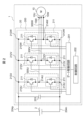
- FIG. 2 is a diagram showing a schematic configuration of the power conversion device.
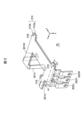
- FIG. 3 is a diagram showing a part of the arrangement of parts in an inverter housing.
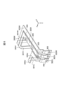
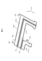
- FIG. 4 is a perspective view showing the appearance of the bus bar module.
- FIG. 5 is another perspective view showing the appearance of the bus bar module.
- FIG. 6 is a diagram showing the shapes of bus bars for three phases.
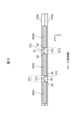
- FIG. 7 is a diagram showing a surface of one of the holder members on the bus bar side.
- FIG. 8 is a diagram showing a surface of the other holder member on the bus bar side.
- FIG. 9 is a cross-sectional view taken along the line A1-A1 of FIG.
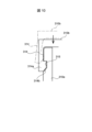
- FIG. 10 is a diagram illustrating the snap-fit mechanism.
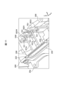
- FIG. 11 is an enlarged view of an inverter housing region where the second bus bar connection portions are arranged.
- FIG. 1 is a perspective view showing the exterior of a mechanically and electrically integrated rotating electric machine device 1 according to the present invention.
- the mechanically and electrically integrated rotating electric machine device 1 is configured by integrating a rotating electric machine 10 and a power conversion device 20.
- the mechanically and electrically integrated rotating electric machine device 1 is used, for example, as a drive device for an electric vehicle.
- the rotating electric machine 10, such as a motor has a substantially cylindrical housing (hereinafter referred to as a motor housing) 10a that houses a rotor and a stator. Note that the details of the area below the portion marked with reference numeral 10a are omitted and shown as a large cylinder and a small cylinder.
- a substantially rectangular parallelepiped housing (hereinafter referred to as an inverter housing) 20a that houses the electrical components that make up the power conversion device 20 is fixed to the upper part of the motor housing 10a by bolts or the like.
- the inverter housing 20a is provided with an upper cover 20b that covers the upper part.
- FIG. 2 is a diagram showing the schematic configuration of the power conversion device 20.
- the power conversion device 20 converts DC power supplied from the DC power source 2 into AC power to drive the rotating electric machine 10.
- the power conversion device 20 includes a power conversion circuit 200, a gate drive circuit 201, a control circuit 202, and a smoothing capacitor 203.
- the power conversion circuit 200 includes U-phase, V-phase, and W-phase power modules 210U, 210V, and 210W.
- Each power module 210U, 210V, 210W has two sets of power semiconductors 211 that form an upper arm and a lower arm.
- Each power module 210U, 210V, 210W has three terminals (connection P terminals 212U, 212V, 212W, connection N terminals 213U, 213V, 213W, connection AC terminals 214U, 214V, 214W).
- the connection P terminals 212U, 212V, 212W are connected to the positive bus line 204p, and the connection N terminals 213U, 213V, 213W are connected to the negative bus line 204n.
- connection AC terminals 214U, 214V, 214W are connected to the motor side connection parts 10U, 10V, 10W that are connected to the windings of the corresponding phases of the rotating electric machine 10 via bus bars 300U, 300V, 300W described later.
- Each power semiconductor 211 switches on/off in response to a drive signal input from the gate drive circuit 201, and converts between DC power and AC power.
- the control circuit 202 inputs on/off commands for each power semiconductor 211 to the gate drive circuit 201 based on commands from a higher-level controller (not shown) installed on the vehicle side.
- a power MOSFET Metal Oxide Semiconductor Field Effect Transistor
- an IGBT Insulated Gate Bipolar Transistor
- the smoothing capacitor 203 is a capacitor for smoothing the current generated by turning on/off the power semiconductor 211 and suppressing ripples in the DC current supplied from the DC power source 2 to the power conversion circuit 200.
- an electrolytic capacitor or a film capacitor is used as the smoothing capacitor 203.
- FIG. 3 is a diagram showing a part of the arrangement of parts in the inverter housing 20a.
- FIG. 3 shows a part of the power conversion device 20 with the top cover 20b covering the top of the inverter housing 20a removed.
- a module housing section 206 for housing the power modules 210U to 210W is provided below the circuit board 215 on which the gate drive circuit 201 and other components are mounted. Although the power module 210W is not shown in FIG. 3, it is arranged above the power module 210V in the figure.
- a refrigerant flow path (not shown) is formed in the module housing section 206, and the power modules 210U to 210W are arranged in the refrigerant flow path.
- the power modules 210U to 210W are cooled by the refrigerant flowing through the refrigerant flow path.
- a supply port 207a for supplying the refrigerant and a discharge port 207b for discharging the refrigerant are provided on the side wall of the inverter housing 20a.
- the inverter housing 20a is provided with a DC connector 205 that is connected to an external DC power source 2.
- the positive terminal 205p of the DC connector 205 is connected to the positive bus line 204p, and the negative terminal 205n is connected to the negative bus line 204n.
- the connection P terminals 212U to 212W of the power modules 210U to 210W are connected to the positive bus line 204p, and the connection N terminals 213U, 213V, and 213W are connected to the negative bus line 204n.
- the busbar module 30 (see FIG. 4), which will be described later, is disposed below the module housing section 206. Although details will be described later, the busbar module 30 includes busbars 300U, 300V, and 300W and a busbar holder 310. Each busbar 300U, 300V, and 300W includes a first busbar connection portion 301U, 301V, and 301W that is connected to the AC connection terminals 214U, 214V, and 214W of the power modules 210U to 210W, and a second busbar connection portion 302U, 302V, and 302W that is connected to the motor side connection portions 10U, 10V, and 10W of the U, V, and W phases on the rotating electric machine 10 side. Note that the first busbar connection portions 301U, 301V and the second busbar connection portions 302U, 302V, and 302W are illustrated in FIG. 3.
- motor side connection parts 10U, 10V, 10W extend from motor housing 10a into region R1 within inverter housing 20a. Therefore, second bus bar connection parts 302U, 302V, 302W of bus bars 300U, 300V, 300W are also arranged in region R1.
- An opening 208 is formed in the side wall of inverter housing 20a in the side wall region facing second bus bar connection parts 302U, 302V, 302W.
- a terminal cover 209 is fixed to opening 208 with bolts or the like, and opening region 208 is covered by terminal cover 209.
- Figures 4 and 5 are perspective views showing the external appearance of the busbar module 30.
- Figure 4 illustrates the busbar module 30 in the same arrangement as in Figure 3 (with the z-axis pointing upward in the figure).
- Figure 5 illustrates a perspective view of the busbar module 30 when the coordinate axes are set so that the z-axis points downward, that is, when viewed from the bottom side of the inverter housing 20a.
- the busbar module 30 includes three busbars 300U, 300V, and 300W corresponding to the U-phase, V-phase, and W-phase, respectively, and a busbar holder 310.
- the busbar module 30 is fixed to the lower part (back side) of the module accommodating section 206 shown in Figure 3 by bolts or the like using a plurality of fixing holes 316 formed in the busbar holder 310.
- FIG. 6 is a diagram showing the shapes of busbars 300U, 300V, and 300W provided in busbar module 30.
- the arrangement of busbars 300U, 300V, and 300W is shown in the same arrangement as that within busbar module 30.
- Busbars 300U, 300V, and 300W are formed from elongated plate-shaped conductive material (e.g., a metal material with excellent conductivity such as oxygen-free copper).
- the bus bar 300U has an extension portion 303U that is routed in an L-shape in the xy plane, and a first bus bar connection portion 301U and a second bus bar connection portion 302U that are provided at both ends of the bus bar 300U and bent in the positive direction of the z axis from the extension portion 303U.
- each bus bar 300V, 300W has an extension portion 303V, 303W that is L-shaped in the xy plane, and a first bus bar connection portion 301V, 301W and a second bus bar connection portion 302V, 302W that bent in the positive direction of the z axis from the extension portion 303V, 303W.
- a fastening hole 305 that is used when connecting the bus bars is formed in each of the bus bar connection portions 301U to 301W and 302U to 302W.
- the busbar holder 310 is formed of an electrically insulating material that covers the extension portions 303U-303W of each busbar 300U-300W. Resin, ceramics, etc. are used as the insulating material. As shown in Figures 4 and 5, the busbar holder 310 is composed of a holder member 310a that covers the positive side of the z-direction of the extension portions 303U-303W, and a holder member 310b that covers the negative side of the z-direction of the extension portions 303U-303W. The busbar connection portions 301U-301W and 302U-302W of the busbars 300U-300W are exposed from the busbar holder 310.
- FIG. 7 is a diagram showing the busbar side surface of holder member 310a.
- FIG. 8 is a diagram showing the busbar side surface of holder member 310b.
- Holder members 310a and 310b are provided with groove 311U in which extension 303U is arranged, groove 311V in which extension 303V is arranged, and groove 311W in which extension 303W is arranged.
- Partitions 312 are formed in region R11 between groove 311U and groove 311V of holder member 310a, and in region R12 between groove 311V and groove 311W of holder member 310a.
- partitions 313 are formed in region R13 between groove 311U and groove 311V of holder member 310b, and in region R14 between groove 311V and groove 311W of holder member 310b.
- FIG. 9 is a diagram showing a cross section taken along line A1-A1 in FIG. 5.
- the configuration of partitions 312, 313 will be described with reference to FIG. 9.
- Partition 312 formed in holder member 310a and partition 313 formed in holder member 310b face each other.
- the pair of opposing partitions 312, 313 on the left side in the figure are arranged to fill gap G11 between extensions 303U and 303V.
- the pair of opposing partitions 312, 313 on the right side in the figure are arranged to fill gap G12 between extensions 303V and 303W.
- the surface of partition 312 facing partition 313 has a centrally located convex surface S1 and concave surface S2 located on both sides of convex surface S1.
- the surface of partition 313 facing partition 312 has a centrally located concave surface S3 and convex surface S4 located on both sides of concave surface S3.
- Convex surface S1 of partition 312 fits into concave surface S3 of partition 313, and convex surface S4 of partition 313 fits into concave surface S2 of partition 312.
- the gaps G11, G12 between the bus bars are filled by the insulating member partitions 312, 313, so that the insulation performance between the phases can be ensured. Furthermore, the contact surface between the partitions 312, 313 has an uneven shape, so that the creepage distance is increased, and the insulation between the phases can be improved.
- the holder members 310a and 310b are joined together using a mechanical joining method called a snap-fit, as shown in FIG. 10.
- the holder member 310b has a joining claw 314 with a protrusion 314a formed thereon, and the holder member 210a has a recess 315 with which the protrusion 314a engages.
- the inclined portion 314b at the tip of the joining claw 314 abuts against the upper end of the holder member 310a, and the joining claw 314 is elastically deformed as shown by the dashed line.
- the protrusion 314a of the joining claw 314 fits into and engages with the recess 315 of the holder member 310a. As a result, the holder members 310a and 310b are joined together.
- FIG. 11 is an enlarged view of the portion where the opening 208 in FIG. 3 where the terminal cover 209 is provided and the second bus bar connection portions 302U-302W of the bus bars 300U-300W are provided.
- the motor side connection portions 10U, 10V, 10W are also shown.
- the opening 208 provided in the side wall of the inverter housing 20a is an opening for connecting the second bus bar connection portions 302U-302W of the bus bars 300U-300W to the motor side connection portions 10U, 10V, 10W.
- a tool or the like is inserted into the inverter housing 20a through this opening 208, and the connection portions are screwed together.
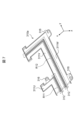
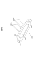
- FIG. 12 is a perspective view showing the external appearance of the terminal cover 209.
- the terminal cover 209 comprises a blocking portion 220 that covers an opening 208 provided in a side wall of the inverter housing 20a, and plate-shaped insulating wall portions 221a, 221b erected on the inner peripheral surface of the blocking portion 220.
- the blocking portion 220 is formed with holes 224 for bolting the terminal cover 209 to the inverter housing 20a.
- the terminal cover 209 is formed from an electrically insulating material (e.g., a resin material).
- FIG. 11 shows a cross section of the terminal cover 209 attached to the opening 208.
- the gap between the blocking portion 220 of the terminal cover 209 and the side wall of the inverter housing 20a is sealed with a sealant 223.
- a metal plate 222 is embedded in the blocking portion 220 of the terminal cover 209.
- the motor connection parts 10U to 10W are pulled out from the motor housing 10a so as to face the opening 208.
- the second bus bar connection parts 302U to 302W of the bus bars 300U to 300W are bent so as to be close to the motor connection parts 10U to 10W, that is, so as to bend along the z-axis direction from the extension parts 303U to 303W.
- the second bus bar connection parts 302U to 302W are arranged so as to overlap in the y-direction with the motor connection parts 10U to 10W of the corresponding phases.
- the screw fastening work is performed through the opening 208 as described above.
- nuts are fixed in advance by welding or the like to the surfaces on the positive side in the y direction of the second bus bar connection parts 302U to 302W, and bolts are inserted through the connection holes 101 of the motor connection parts 10U to 10W and fastened to the nuts.
- the motor connection parts 10U to 10W and the second bus bar connection parts 302U to 302W are arranged in the y direction in this order, but they may also be arranged in the reverse order. In that case, the nuts are fixed to the motor connection parts 10U to 10W.
- Gaps G are provided between the motor connection part 10U and the second bus bar connection part 302U and the motor connection part 10V and the second connection part 302V, and between the motor connection part 10V and the second bus bar connection part 302V and the motor connection part 10W and the second bus bar connection part 302W.
- the insulating wall parts 221a and 221b of the terminal cover 209 fixed to the opening 208 are inserted into the gaps G. By inserting the insulating wall parts 221a and 221b into the gaps G, it is possible to maintain the interphase insulation performance at the connection part where the conductor is exposed.
- the metal plate 222 is embedded in the blocking part 220 that covers the opening 208, the radiation noise generated by the AC current is shielded by the metal plate 222, and the radiation noise leaking to the outside from the inverter housing 20a can be suppressed.
- the terminal cover 209 is attached to the opening 208 and fixed with bolts.
- the insulating wall parts 221a, 221b protruding from the opening 208 into the housing are each inserted into the gap G.
- the blocking part 220 is placed at a predetermined position in the opening 208, and then fixed with bolts.
- the insulating wall parts 221a, 221b also function as guides when attaching the terminal cover 209 to the opening 208. This improves the workability when assembling the terminal cover 209.
- the mechanically and electrically integrated rotating electric machine device 1 comprises a rotating electric machine 10, a power conversion device 20 connected to the rotating electric machine 10, an inverter housing 20a (housing) that accommodates the rotating electric machine 10 and the power conversion device 20, a busbar module 30 that electrically connects multiple connection AC terminals 214U to 214W (first connection portions) of the power conversion device 20 to multiple motor side connection portions 10U to 10W (second connection portions) of the rotating electric machine 10, an opening 208 provided in a wall portion of the inverter housing 20a and facing the multiple motor side connection portions 10U to 10W, and a terminal cover 209 (cover) that covers the opening 208.
- the bus bar module 30 has first bus bar connection portions 301U to 301W connected to the AC connection terminals 214U to 214W, extension portions 303U to 303W extending from the first bus bar connection portions 301U to 301W to the motor side connection portions 10U to 10W, and second bus bar connection portions 302U to 302W bent from the extension portions 303U to 303W to be connected to the motor side connection portions 10U to 10W, and is arranged such that the second bus bar connection portions 302U to 302W are spaced apart from the bus bars 300U to 300W.
- the terminal cover 209 has an electrically insulating busbar holder 310 that covers the extensions 303U-303W of the multiple busbars 300U-300W that are connected to the terminal cover 209, and has a blocking portion 220 (opening closing portion) that closes the opening 208, and electrically insulating insulating wall portions 221a, 221b (partition portions) that protrude from the blocking portion 220 toward the multiple motor side connection portions 10U-10W to which the second busbar connection portions 302U-302W are connected and are inserted between the adjacent second busbar connection portions 302U-302W.
- the insulating wall portions 221a, 221b of the terminal cover 209 are inserted between the second bus bar connection portions 302U-302W, so that interphase insulation can be ensured at the bent and exposed second bus bar connection portions 302U-302W.
- the bus bar holder 310 can be configured to cover the extension portions 303U-303W excluding the second bus bar connection portions 302U-302W, so that the shape of the insulating mold can be simplified regardless of the shape of the second bus bar connection portions 302U-302W, and the amount of molding material can be reduced.
- the bus bar holder 310 and the terminal cover 209 can ensure insulation at the extension portions 303U-303W, which are the wiring areas of the bus bars 300U-300W, and at the second bus bar connection portions 302U-302W, which are the motor connection areas.
- the insulating walls 221a and 221b function as guides when attaching the terminal cover 209 to the opening 208, improving the workability when attaching the terminal cover 209 to the opening 208.
- the busbar holder 310 integrally covers the multiple extensions 303U to 303W that are spaced apart.
- the busbar holder 310 integrally covers the multiple extensions 303U to 303W that are spaced apart.
- the busbar holder 310 is not provided, the extensions 303U to 303W will vibrate due to vehicle vibration, making the busbar more likely to become misaligned.
- the extensions 303U to 303W can be suppressed.
- the bus bars 300U to 300W are formed of a plate-shaped conductor, and the extensions 303U to 303W are arranged side by side with gaps G11, G12 in a direction perpendicular to the front and back directions of the plate-shaped conductor.
- the bus bar holder 310 includes an electrically insulating holder portion 310a (first holder member) that covers the front side of the extensions 303U to 303W, and an electrically insulating holder portion 310b (second holder member) that covers the back side of the extensions 303U to 303W.
- a partition portion 312 (first partition portion) of the holder portion 310a (first holder member) and a partition portion 313 (second partition portion) of the holder portion 310b (second holder member) are arranged in the gaps G11, G12.
- the opposing surfaces of the partition portion 312 and the partition portion 313 respectively have convex portions S1, S4 and concave portions S2, S3, and the convex portion S1 of the partition portion 312 fits into the concave portion S3 of the partition portion 313, and the convex portion S4 of the partition portion 313 fits into the concave portion S2 of the partition portion 312.
- the terminal cover 209 may be made of an electrically insulating material. In this way, by forming the entire terminal cover 209, including the insulating wall portions 221a and 221b, from an electrically insulating material, processing costs can be reduced.
- a metal plate 222 is embedded in the closing portion 220 (opening closing portion) of the terminal cover 209. In this way, by embedding the metal plate 222 in the closing portion 220 that covers the opening 208, the radiation noise generated by the AC current is shielded by the metal plate 222, and the radiation noise leaking to the outside from the inverter housing 20a can be suppressed.
- the second bus bar connection portions 302U-302W are bent from the extension portions 303U-303W so that one of the front and back sides faces the opening 208, and the motor side connection portions 10U-10W (second connection portions) are arranged to face one of the front and back sides of the second bus bar connection portions 302U-302W. Since the motor side connection portions 10U-10W and the second bus bar connection portions 302U-302W arranged to overlap in this manner are arranged to face the opening 208, the fastening operation can be easily performed via the opening 208.
- the second bus bar connection parts 302U to 302W which are bent from the extension parts 303U to 303W, are exposed from the bus bar holder 310 as shown in FIG. 5, but the insulating wall parts 221a and 221b of the terminal cover 209 are inserted between the adjacent second bus bar connection parts 302U to 302W to ensure interphase insulation.
Landscapes
- Engineering & Computer Science (AREA)
- Power Engineering (AREA)
- Microelectronics & Electronic Packaging (AREA)
- Motor Or Generator Frames (AREA)
Abstract
Description
Claims (7)
- 回転電機と、
前記回転電機に接続される電力変換装置と、
前記回転電機および前記電力変換装置を収容する筐体と、
前記電力変換装置の複数の第1接続部と前記回転電機の複数の第2接続部とを電気的に接続するバスバモジュールと、
前記筐体の壁部に設けられ、複数の前記第2接続部に対向する開口部と、
前記開口部を覆うカバーと、を備え、
前記バスバモジュールは、
前記第1接続部に接続される第1バスバ接続部、該第1バスバ接続部から前記第2接続部へと延びる延伸部、および、該延伸部から屈曲して前記第2接続部と接続される第2バスバ接続部を有する複数のバスバと、
前記第2バスバ接続部が離間するように配置された複数の前記バスバの前記延伸部を覆う、電気絶縁性のバスバホルダと、を有し、
前記カバーは、
前記開口部を閉鎖する開口閉鎖部と、
前記開口閉鎖部から前記第2バスバ接続部が接続された複数の前記第2接続部に向かって突出し、互いに隣接する前記第2バスバ接続部の間に挿入される電気絶縁性の隔壁部と、を有する機電一体型回転電機装置。 - 請求項1に記載の機電一体型回転電機装置において、
前記バスバホルダは、離間して配置された複数の前記延伸部を一体に覆う、機電一体型回転電機装置。 - 請求項2に記載の機電一体型回転電機装置において、
複数の前記バスバは板状導体で形成され、複数の前記延伸部は前記板状導体の表裏方向と直行する方向に隙間を空けて並置され、
前記バスバホルダは、複数の前記延伸部の表面側を覆う電気絶縁性の第1ホルダ部材と、複数の前記延伸部の裏面側を覆う電気絶縁性の第2ホルダ部材とを備える、機電一体型回転電機装置。 - 請求項3に記載の機電一体型回転電機装置において、
前記隙間には、前記第1ホルダ部材の有する第1仕切部と前記第2ホルダ部材の有する第2仕切部とが配設され、
前記第1仕切部および前記第2仕切部の互いの対向面はそれぞれ凸面部と凹面部とを有し、
前記第1仕切部の前記凸面部は前記第2仕切部の前記凹面部に嵌まり込み、前記第2仕切部の前記凸面部は前記第1仕切部の前記凹面部に嵌まり込む、機電一体型回転電機装置。 - 請求項1に記載の機電一体型回転電機装置において、
前記カバーは電気絶縁性の材料で形成されている、機電一体型回転電機装置。 - 請求項5に記載の機電一体型回転電機装置において、
前記カバーの前記開口閉鎖部には金属板が埋設されている、機電一体型回転電機装置。 - 請求項3に記載の機電一体型回転電機装置において、
前記第2バスバ接続部は、表裏面の一方が前記開口部と対向するように前記延伸部から屈曲し、
前記第2接続部は、前記第2バスバ接続部の表裏面の一方に対向して配置される、機電一体型回転電機装置。
Priority Applications (4)
| Application Number | Priority Date | Filing Date | Title |
|---|---|---|---|
| PCT/JP2023/024267 WO2025004286A1 (ja) | 2023-06-29 | 2023-06-29 | 機電一体型回転電機装置 |
| JP2025529138A JPWO2025004286A1 (ja) | 2023-06-29 | 2023-06-29 | |
| DE112023005558.0T DE112023005558T5 (de) | 2023-06-29 | 2023-06-29 | Mechanisch-elektrisch integrierte rotierende elektrische maschinenvorrichtung |
| CN202380094856.7A CN120752836A (zh) | 2023-06-29 | 2023-06-29 | 机电一体型旋转电机装置 |
Applications Claiming Priority (1)
| Application Number | Priority Date | Filing Date | Title |
|---|---|---|---|
| PCT/JP2023/024267 WO2025004286A1 (ja) | 2023-06-29 | 2023-06-29 | 機電一体型回転電機装置 |
Publications (1)
| Publication Number | Publication Date |
|---|---|
| WO2025004286A1 true WO2025004286A1 (ja) | 2025-01-02 |
Family
ID=93938239
Family Applications (1)
| Application Number | Title | Priority Date | Filing Date |
|---|---|---|---|
| PCT/JP2023/024267 Ceased WO2025004286A1 (ja) | 2023-06-29 | 2023-06-29 | 機電一体型回転電機装置 |
Country Status (4)
| Country | Link |
|---|---|
| JP (1) | JPWO2025004286A1 (ja) |
| CN (1) | CN120752836A (ja) |
| DE (1) | DE112023005558T5 (ja) |
| WO (1) | WO2025004286A1 (ja) |
Citations (3)
| Publication number | Priority date | Publication date | Assignee | Title |
|---|---|---|---|---|
| JP2004327184A (ja) * | 2003-04-23 | 2004-11-18 | Yazaki Corp | 端子台 |
| JP2014138446A (ja) * | 2013-01-15 | 2014-07-28 | Toyota Motor Corp | パワーケーブルの接続構造 |
| JP6409968B2 (ja) * | 2015-05-26 | 2018-10-24 | 日産自動車株式会社 | 機電一体型の回転電機装置 |
-
2023
- 2023-06-29 CN CN202380094856.7A patent/CN120752836A/zh active Pending
- 2023-06-29 DE DE112023005558.0T patent/DE112023005558T5/de active Pending
- 2023-06-29 WO PCT/JP2023/024267 patent/WO2025004286A1/ja not_active Ceased
- 2023-06-29 JP JP2025529138A patent/JPWO2025004286A1/ja active Pending
Patent Citations (3)
| Publication number | Priority date | Publication date | Assignee | Title |
|---|---|---|---|---|
| JP2004327184A (ja) * | 2003-04-23 | 2004-11-18 | Yazaki Corp | 端子台 |
| JP2014138446A (ja) * | 2013-01-15 | 2014-07-28 | Toyota Motor Corp | パワーケーブルの接続構造 |
| JP6409968B2 (ja) * | 2015-05-26 | 2018-10-24 | 日産自動車株式会社 | 機電一体型の回転電機装置 |
Also Published As
| Publication number | Publication date |
|---|---|
| CN120752836A (zh) | 2025-10-03 |
| JPWO2025004286A1 (ja) | 2025-01-02 |
| DE112023005558T5 (de) | 2025-12-04 |
Similar Documents
| Publication | Publication Date | Title |
|---|---|---|
| CN103023279B (zh) | 半导体控制装置 | |
| CN102148562B (zh) | 能量转换装置 | |
| CN103733496B (zh) | 电力转换装置 | |
| JP5144945B2 (ja) | 一体型電動圧縮機 | |
| US9048721B2 (en) | Semiconductor device | |
| US12395048B2 (en) | Controller and motor assembly comprising same | |
| US11444510B2 (en) | Controller and motor assembly comprising same | |
| US12301128B2 (en) | Half-bridge for an electric drive of an electric vehicle or a hybrid vehicle, power module for an inverter and inverter | |
| JP4538474B2 (ja) | インバータ装置 | |
| JP2004327184A (ja) | 端子台 | |
| JP7212143B2 (ja) | 電力変換装置および電力変換装置の製造方法 | |
| US10389214B2 (en) | Motor and producing method for motor | |
| JP7551927B2 (ja) | 電力変換装置 | |
| CN116614983A (zh) | 电路装置、电驱动装置和机动车 | |
| JP2004031590A (ja) | 半導体装置 | |
| JP2013074671A (ja) | 半導体制御装置 | |
| JP2005332879A (ja) | 電子ユニット | |
| CN120752836A (zh) | 机电一体型旋转电机装置 | |
| JP3922698B2 (ja) | 半導体装置 | |
| JP5816504B2 (ja) | 半導体装置 | |
| US20230128774A1 (en) | Power module with overmoulding, devices comprising such a power module and method for manufacturing a power module with overmoulding | |
| WO2025032647A1 (ja) | 基板ユニットおよび電子装置 | |
| JP5698637B2 (ja) | 半導体装置 | |
| WO2026094896A1 (ja) | 電力変換装置 | |
| WO2026069805A1 (ja) | モータ制御装置 |
Legal Events
| Date | Code | Title | Description |
|---|---|---|---|
| 121 | Ep: the epo has been informed by wipo that ep was designated in this application |
Ref document number: 23943678 Country of ref document: EP Kind code of ref document: A1 |
|
| WWE | Wipo information: entry into national phase |
Ref document number: 202380094856.7 Country of ref document: CN |
|
| WWE | Wipo information: entry into national phase |
Ref document number: 112023005558 Country of ref document: DE |
|
| ENP | Entry into the national phase |
Ref document number: 2025529138 Country of ref document: JP Kind code of ref document: A |
|
| WWE | Wipo information: entry into national phase |
Ref document number: 2025529138 Country of ref document: JP |
|
| WWP | Wipo information: published in national office |
Ref document number: 202380094856.7 Country of ref document: CN |
|
| WWP | Wipo information: published in national office |
Ref document number: 112023005558 Country of ref document: DE |
|
| 122 | Ep: pct application non-entry in european phase |
Ref document number: 23943678 Country of ref document: EP Kind code of ref document: A1 |