WO2025004194A1 - 制御装置、ロボットシステム、および制御方法 - Google Patents
制御装置、ロボットシステム、および制御方法 Download PDFInfo
- Publication number
- WO2025004194A1 WO2025004194A1 PCT/JP2023/023847 JP2023023847W WO2025004194A1 WO 2025004194 A1 WO2025004194 A1 WO 2025004194A1 JP 2023023847 W JP2023023847 W JP 2023023847W WO 2025004194 A1 WO2025004194 A1 WO 2025004194A1
- Authority
- WO
- WIPO (PCT)
- Prior art keywords
- robot
- force
- control mode
- control device
- information
- Prior art date
- Legal status (The legal status is an assumption and is not a legal conclusion. Google has not performed a legal analysis and makes no representation as to the accuracy of the status listed.)
- Ceased
Links
Images


Classifications
-
- B—PERFORMING OPERATIONS; TRANSPORTING
- B25—HAND TOOLS; PORTABLE POWER-DRIVEN TOOLS; MANIPULATORS
- B25J—MANIPULATORS; CHAMBERS PROVIDED WITH MANIPULATION DEVICES
- B25J13/00—Controls for manipulators
- B25J13/08—Controls for manipulators by means of sensing devices, e.g. viewing or touching devices
- B25J13/085—Force or torque sensors
-
- B—PERFORMING OPERATIONS; TRANSPORTING
- B25—HAND TOOLS; PORTABLE POWER-DRIVEN TOOLS; MANIPULATORS
- B25J—MANIPULATORS; CHAMBERS PROVIDED WITH MANIPULATION DEVICES
- B25J9/00—Program-controlled manipulators
- B25J9/16—Program controls
- B25J9/1628—Program controls characterised by the control loop
- B25J9/1633—Program controls characterised by the control loop compliant, force, torque control, e.g. combined with position control
Definitions
- This disclosure relates to a control device for controlling the operation of a robot, a robot system, and a control method.
- One of the techniques used when creating a control program to control the operation of a robot is for a worker to operate the robot and determine the position and orientation of the control point within the robot relative to the workpiece.
- This work by the worker is called teaching work.
- An operating method called direct teach is known as a function aimed at simplifying robot operation in teaching work. With direct teach, the worker directly touches the robot arm and applies force in the desired direction of movement, causing the robot to move in the direction of the applied force and move to the desired position. Direct teach allows the worker to intuitively operate the robot, so it is widely used to operate collaborative robots, etc.
- Direct teach allows the operator to intuitively operate the device, but it is difficult to achieve highly accurate position adjustments. For example, if the operator wishes to move the end effector located at the tip of the robot by about 0.1 mm in the Z-axis direction only in order to fine-tune the height of the end effector, the operator must transmit a small amount of force only in the Z-axis direction without generating any force in the X- or Y-axis directions, forcing delicate control of the direction and magnitude of the force.
- the control device described in Patent Document 1 provides a first control mode for normal control and a second control mode for detailed position adjustment, and selects the second control mode when the duration during which the force magnitude is equal to or greater than the force threshold is less than the duration threshold, and selects the first control mode when the duration is equal to or greater than the duration threshold, proposing a highly accurate position adjustment method that automates the switching of control modes.
- Patent Document 1 does not allow the operator to instantly switch control modes at the timing intended.
- the control mode is switched even if the magnitude of the force decreases only for an instant. This causes a timing when the control mode is changed to one that the operator does not want, and this causes the problem that highly accurate teaching cannot be easily achieved.
- This disclosure has been made in consideration of the above, and aims to provide a control device that can easily achieve highly accurate teaching.
- control device of the present disclosure includes an external force calculation unit that calculates force information, which is information on the force and moment applied to the robot by the worker, based on the force and moment applied to the robot by the worker and the position and posture of the robot control point, which is the control point of the robot by the worker.
- the control device of the present disclosure also includes a control mode determination unit that determines whether to select a normal control mode, which controls the robot so that the greater the force and moment of the force information, the faster the robot moves, or a detailed control mode, which controls the robot while restricting at least one of the robot's motion speed and motion direction, based on speed information, which is information on the robot's speed or angular velocity, and the force information.
- the control device of the present disclosure also includes an operation command generation unit that generates an operation command corresponding to the normal control mode when the normal control mode is selected and outputs it to the robot, and that generates an operation command corresponding to the detailed control mode when the detailed control mode is selected and outputs it to the robot.
- the control device disclosed herein has the effect of easily achieving highly accurate teaching.
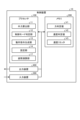
- FIG. 1 is a diagram showing a configuration of a control device according to a first embodiment
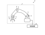
- FIG. 1 is a diagram showing a configuration of a robot system including a control device according to a first embodiment.
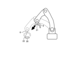
- FIG. 1 is a diagram for explaining an operation of an end effector when the control device according to the first embodiment executes a normal control mode
- FIG. 13 is a diagram for explaining an operation of an end effector when the control device according to the first embodiment executes a detailed control mode
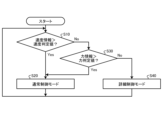
- 1 is a flowchart showing a procedure of a process executed by a control device according to a first embodiment in a direct teach control mode.
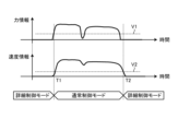
- FIG. 1 is a diagram for explaining an example of a control mode selected by the control device according to the first embodiment for a first example of force information and velocity information
- FIG. 1 is a diagram showing a configuration of a control device according to a first embodiment
- FIG. 1 is a diagram showing a configuration of a robot system including a control device according to a first embodiment.
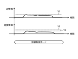
- FIG. 11 is a diagram for explaining an example of a control mode selected by the control device according to the first embodiment for a second example of force information and velocity information;
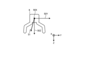
- FIG. 11 is a diagram for explaining an operation direction that the control device according to the second embodiment determines based on the direction of a force vector detected by a force detection unit during a detailed control mode.
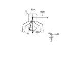
- FIG. 11 is a diagram for explaining an operation direction that the control device according to the second embodiment determines based on the direction of a moment vector detected by a force detection unit during a detailed control mode.
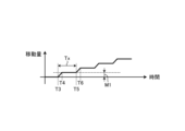
- FIG. 13 is a diagram for explaining the movement amount of the end effector in a detailed control mode controlled by the control device according to the third embodiment;
- FIG. 1 is a diagram showing an example of a hardware configuration for implementing a control device according to first to third embodiments;
- Embodiment 1. 1 is a diagram showing a configuration of a control device according to the first embodiment.
- the control device 10 is a device for controlling the operation of a robot (a robot 1 described later).
- the control device 10 controls an actuator 3 described later to cause the robot 1 to perform a desired operation.
- the control device 10 controls the robot 1 in a position control mode or a direct teach control mode.
- the position control mode is a control mode in which the robot 1 is controlled according to a position command.
- the direct teach control mode is a control mode in which the operator manually operates the robot 1 by directly applying an external force to an end effector 6 (described below) equipped on the robot 1. The location where the operator applies the force is a movable location on the robot 1.
- control point robot control point 7, described later
- the control point where the operator applies an external force is not limited to the end effector 6, but may be any position, such as the arm part of the robot arm or a joint part of the robot arm.
- Direct teach control modes include a normal control mode, which will be described later, and a detailed control mode, which will be described later. By using direct teach, the operator can teach the control device 10 the operating position of the robot 1.
- the control device 10 of the first embodiment automatically switches from the normal control mode and the detailed control mode to a control mode that matches the intention of the operator during the work.
- the control device 10 In the direct teach control mode, the control device 10 generates an operation command for moving the robot 1 to a position to which the worker moved the robot 1, based on the manual operation of the robot 1 by the worker.
- the operation command generated by the control device 10 is a command for controlling the operation of the robot 1.
- the control device 10 When the control device 10 generates the operation command, it controls the position of the robot 1 in accordance with the operation command. In this way, the control device 10 executes control of the robot 1 using the operation command generated in the direct teach control mode.
- the control device 10 is connected to the force detection unit 5 and the position detection unit 4.
- the control device 10 includes an external force calculation unit 11, a control mode determination unit 12, an operation command generation unit 13, a setting unit 14, a memory unit 15, a display unit 16, and an attitude calculation unit 17.
- the force detection unit 5 is disposed, for example, between the tip of the robot arm provided on the robot 1 and the end effector 6.
- the force detection unit 5 is a sensor that measures the force and moment acting on the end effector 6.
- the force detection unit 5 transmits the measured force and moment to the control device 10. In this way, the force detection unit 5 detects the external force applied to the end effector 6 and transmits it to the control device 10.
- the force detection unit 5 may directly measure the force and moment acting on the end effector 6 using a six-axis force sensor that measures force and moment, but may also measure it by other means.
- the force detection unit 5 may measure the force and moment by calculating the force acting on the hand of the robot 1 using torque sensors attached to all joints of the robot 1.
- the position detection unit 4 is disposed at a joint of the robot arm of the robot 1.
- the position detection unit 4 is a sensor that detects the rotation angle of the actuator 3 (described below) that is disposed at the joint.
- the rotation angle detected by the position detection unit 4 is used for feedback control of the actuator 3 and is also transmitted to the control device 10.
- the posture calculation unit 17 calculates the position and posture of the robot control point 7, which is the work point of the robot 1, by performing a calculation using forward kinematics on the rotation angle detected by the position detection unit 4.
- the robot control point 7 is a point that is moved by the worker during direct teaching, and the control device 10 generates a control program based on the position of the robot control point 7 taught by the worker.
- the posture calculation unit 17 can calculate the speed and angular velocity of the robot control point 7 based on the calculated information on the change in position and posture of the robot control point 7 (difference information).
- the attitude calculation unit 17 calculates the position and attitude based on the detected rotation angle, and calculates the velocity, angular velocity, acceleration, and angular acceleration based on the information on the changes in the calculated position and attitude.
- the external force calculation unit 11 removes the effects of gravity, inertial force, centrifugal force, Coriolis force, etc. of the robot arm from the measured force and moment, and calculates the force (external force) and moment applied by the operator to the tip of the robot 1. In other words, the external force calculation unit 11 calculates the operating force applied by the operator based on the measured operating force.
- the dynamics model used to calculate gravity, inertial force, centrifugal force, Coriolis force, etc. is stored in the memory unit 15.
- the external force calculation unit 11 calculates the operating force applied by the operator using the dynamics model read out from the memory unit 15. Specifically, the external force calculation unit 11 calculates the force and moment applied to the tip of the robot 1 by applying to the dynamics model the force and moment detected by the force detection unit 5, the position, attitude, speed, and angular velocity calculated by the attitude calculation unit 17, and the acceleration and angular acceleration calculated by the external force calculation unit 11.
- the force and moment detected based on the movement of the robot 1 should be approximately the same as the force and moment detected using the sensor. Therefore, when there is a difference between the force and moment detected based on the movement of the robot 1 and the force and moment detected using the sensor, this difference is considered to be the operating force applied by the operator. Therefore, the external force calculation unit 11 may calculate the operating force applied by the operator based on the difference between the force and moment detected based on the movement of the robot 1 and the force and moment detected using the sensor.
- the force and moment detected by the force detection unit 5 may be referred to as the detected force and detected moment, respectively.
- the external force calculation unit 11 transmits the calculated operating force (the force and moment applied by the operator) to the control mode determination unit 12 and the operation command generation unit 13.
- the control mode determination unit 12 determines the control mode in the direct teach control mode based on the operating force (force information), which is the force and moment calculated by the external force calculation unit 11, and the change rate information detected by the position detection unit 4.
- the change rate information detected by the position detection unit 4 is, for example, velocity data indicating the speed of the movement of the actuator 3.
- the change rate information may be angular velocity data indicating the angular velocity of the movement of the actuator 3.
- the velocity data corresponds to the change rate of the position of the robot control point 7, and each velocity data corresponds to the change rate of the attitude of the robot control point 7.
- the control mode used by the control device 10 of the first embodiment in the direct teach control mode is either the normal control mode or the detailed control mode.
- the normal control mode is a normal direct teach control mode intended for use in roughly adjusting the position of the robot 1.
- a feedback control system force feedback control system and moment feedback control system
- the robot 1 moves in the direction of the force and moment applied to it, and the greater the force and moment, the faster the movement speed.
- the detailed control mode is a direct teach control mode intended for use in fine position adjustment of the robot 1.
- the detailed control mode at least one of the motion speed and motion direction of the robot 1 during direct teach is restricted in order to make it easier to perform fine position adjustment.
- the detailed control mode restricts the motion speed to a predetermined value or the motion direction to a predetermined direction by setting at least one of an upper limit value for the motion speed and an operable axial direction for the control system in the normal control mode.
- the control mode determination unit 12 determines whether to apply the normal control mode or the detailed control mode. If the control mode determination unit 12 determines that the robot 1 is to be controlled in the detailed control mode, it determines the axis to be operated (hereinafter referred to as the operable axis).
- the operable axis is, for example, an axial direction along which the end effector 6 is moved. In other words, the operable axis is, for example, an axial direction along which the movement of the end effector 6 is permitted.
- the control mode determination unit 12 transmits the operation mode determination result and the operable axis to the operation command generation unit 13.
- the motion command generator 13 generates a motion command (robot motion command) for the robot 1 based on the operating force calculated by the external force calculator 11 and the control mode and operable axes determined by the control mode determiner 12.
- the controller 10 sets up a force control system that causes the robot 1 to operate in a direction that cancels the operating force.
- the motion command generation unit 13 In normal control mode, which allows for rough position adjustment of the robot 1, the motion command generation unit 13 generates motion commands so that the greater the force and moment applied by the worker, the faster the robot 1 will move.
- the motion command generation unit 13 generates motion commands so that the motion speed and the axial direction in which motion can be performed are restricted, regardless of the magnitude of the force and moment applied by the operator.
- the upper limit of the movement speed and the movable axes (directions in which movement is possible) in the detailed control mode can be changed in advance by the operator.
- the upper limit of the movement speed and the movable axes in the detailed control mode are registered in the memory unit 15 via the setting unit 14.
- the movement command generating unit 13 generates a movement command in the detailed control mode based on at least one of the upper limit of the movement speed and the movable axes registered in the memory unit 15. As a result, restrictions are imposed on the movement speed and direction of the robot 1 in the detailed control mode.
- the axial directions in which the robot can operate in the detailed control mode are one or two of the X-axis, Y-axis, and Z-axis directions.
- the control device 10 moves the robot 1 only in a direction parallel to the X-axis direction, and does not move the robot 1 in the Y-axis or Z-axis directions.
- the control device 10 extracts only the force in the X-axis direction from the force applied to the robot 1 and moves the robot 1 in the X-axis direction.
- the control device 10 moves the robot 1 in a plane parallel to the XY plane, and does not move it in the Z-axis direction.
- the Cartesian coordinate system (orthogonal coordinate system) indicated by the X-axis, Y-axis, and Z-axis directions can be defined arbitrarily.
- the operator can preselect the world coordinate system, the tool coordinate system attached to the robot hand, or the work coordinate system attached to the target work (work 30 described below) as the Cartesian coordinate system.
- the tool coordinate system is a coordinate system defined with the position of the tool attached to the tip of the robot arm as its origin.
- the work coordinate system is a coordinate system defined with the position of the placed work 30 as its origin.
- the control device 10 operates the end effector 6 only in the axial direction that is preset by the operator in a coordinate system predefined by the operator. In this way, when restricting the movement direction in the detailed control mode, the control device 10 limits the operable directions to directions parallel to any of the X-axis direction, Y-axis direction, and Z-axis direction in the predefined Cartesian coordinate system.
- the control device 10 may operate the end effector 6 only in a pre-set axis direction among the A-axis direction around the X-axis direction, the B-axis direction around the Y-axis direction, and the C-axis direction around the Z-axis direction in a Cartesian coordinate system.
- the control device 10 may operate the end effector 6 only in a direction parallel to one or two of the A-axis direction, B-axis direction, and C-axis direction. In other words, the control device 10 may limit the direction of operation to, for example, a rotation direction around any one of the X-axis direction, Y-axis direction, and Z-axis direction in a pre-defined Cartesian coordinate system.
- the motion command generating unit 13 reads out the upper limit of the motion speed and the movable axis, which is the direction of the movable axis, from the memory unit 15. In the detailed control mode, the motion command generating unit 13 generates a motion command to move the robot control point 7 at a motion speed slower than the upper limit of the motion speed read out from the memory unit 15 and in the axial direction of the movable axis.
- the setting unit 14 receives various control settings used for control sent from an external terminal or the like, and sets them as control information. For example, the setting unit 14 receives control settings input by an operator to an external terminal or the like from the external terminal, and sets them as control information. The setting unit 14 receives control settings from an external terminal or the like when the control information is changed. The setting unit 14 stores the control information in the memory unit 15 or the like.
- the memory unit 15 stores physical information related to the dynamics model of the robot 1, and various information used for control (such as control settings). Examples of information stored in the memory unit 15 include information on the coordinate system used by the control device 10, the upper limit of the operating speed in detailed control mode, and information on operable axes.
- the display unit 16 displays information used by the control device 10. Note that the display unit 16 does not have to be included as a component of the control device 10. In this case, the display unit 16 is disposed outside the control device 10 and connected to the control device 10.
- control device 10 of the first embodiment switches between the normal control mode and the detailed control mode based on the force information (force and moment calculated by the external force calculation unit 11), which is the operating force applied by the operator, and the rate of change of the position or posture of the robot control point 7 (velocity data or angular velocity data).
- FIG. 2 is a diagram showing the configuration of a robot system equipped with a control device according to the first embodiment.
- the robot system 2 includes a robot 1 and a control device 10.
- the control device 10 is connected to the robot 1, and the control device 10 controls the robot 1.
- the robot 1 has one or more joints.
- the robot 1 is equipped with an actuator 3 and a position detection unit 4 at each joint.
- the control device 10 controls the posture of the robot 1 by driving the actuator 3 based on the position, posture, speed, and angular velocity detected by the position detection unit 4.
- the robot 1 also has a force detection unit 5 at the tip of the robot arm.
- the robot 1 also has an end effector 6 such as a hand mounted on the tip of the force detection unit 5.
- the robot control point 7 is, for example, any position within the end effector 6.
- the robot control point 7 can be arbitrarily changed by the operator.
- the control device 10 controls the robot 1 in direct teach control mode based on the robot control point 7 set by the operator.
- the control device 10 switches the control mode between the normal control mode and the detailed control mode using the force information (detected force and detected moment) detected by the force detection unit 5 and the rate of change information (velocity and angular velocity) detected by the position detection unit 4.
- Figure 3 is a diagram for explaining the operation of the end effector when the control device according to the first embodiment executes the normal control mode.
- the normal control mode is a control mode that is applied when rough position adjustment of the robot 1 is performed.
- the operator may move the end effector 6 with great force or at high speed.
- Figure 3 shows a case where the operator moves the end effector 6 with great force or at high speed from position 21 to position 22, which is a position near the position where the workpiece 30 is placed.
- FIG. 4 is a diagram for explaining the operation of the end effector when the control device according to the first embodiment executes the detailed control mode.
- the direction perpendicular to the plane of FIG. 4 is the X-axis direction
- two directions perpendicular to each other within the plane of FIG. 4 are the Y-axis direction and the Z-axis direction.
- the detailed control mode is a control mode that is applied when detailed position adjustment of the robot 1 is executed.
- Figure 4 shows a case where the operator moves the end effector 6 from position 23 to position 24, where the workpiece 30 is placed, with a small force and at a low speed.
- the teaching work for the robot 1 can be broadly divided into work for moving the end effector 6 to the vicinity of the teaching position (hereinafter sometimes referred to as a large movement work) as shown in FIG. 3, and work for fine-tuning the end effector 6 to a detailed position (hereinafter sometimes referred to as a small movement work) as shown in FIG. 4.
- a large movement work work for moving the end effector 6 to the vicinity of the teaching position
- a small movement work work for fine-tuning the end effector 6 to a detailed position
- the control device 10 selects the normal control mode.
- the control device 10 selects the detailed control mode.
- the control device 10 applies the normal control mode when the force information applied to the end effector 6 by the operator is greater than a specific value (a force judgment value described later), or when the speed information of the end effector 6 moved by the operator is greater than a specific value (a speed judgment value described later). In this case, the control device 10 moves the end effector 6 in the direction of the force applied to the end effector 6 at a speed or angular velocity according to the magnitude of the force.
- the control device 10 applies the detailed control mode when the force information applied by the operator to the end effector 6 is equal to or less than the force judgment value, and the speed information of the end effector 6 moved by the operator is equal to or less than the speed judgment value. In this case, the control device 10 imposes a restriction on at least one of the moving speed and moving direction of the end effector 6.
- the force information used by the control device 10 when determining whether to apply the normal control mode or the detailed control mode is the force and moment applied by the operator to the end effector 6. Therefore, the force judgment value includes information on the reference value of the force and information on the reference value of the moment.
- the control device 10 determines that the force information is greater than the force judgment value when at least one of the following is true: the force applied by the operator to the end effector 6 is greater than the reference force value, and the moment applied by the operator to the end effector 6 is greater than the reference moment value.
- the control device 10 determines that the force information is equal to or less than the force judgment value.
- the speed information used by the control device 10 when determining whether to apply the normal control mode or the detailed control mode is the speed and angular velocity of the end effector 6 moved by the operator. Therefore, the speed determination value includes information on the reference value of the speed and information on the reference value of the angular velocity.
- the control device 10 determines that the speed information is greater than the speed judgment value when at least one of the following is true: the speed of the end effector 6 moved by the worker is greater than the speed reference value, and the angular velocity of the end effector 6 moved by the worker is greater than the angular velocity reference value.
- control device 10 determines that the speed information is equal to or less than the speed judgment value when the speed of the end effector 6 moved by the worker is equal to or less than the speed reference value and when the angular velocity of the end effector 6 moved by the worker is equal to or less than the angular velocity reference value.
- control device 10 applies the normal control mode when any one of the following conditions C1 to C4 is satisfied.
- C1 The force applied to the end effector 6 is greater than the reference force value.
- C2 The moment applied to the end effector 6 is greater than the reference moment value.
- C3 The velocity of the end effector 6 is greater than the reference velocity value.
- C4 The angular velocity of the end effector 6 is greater than the reference angular velocity value.
- control device 10 applies the detailed control mode when all of the following conditions C5 to C8 are satisfied.
- C5 The force applied to the end effector 6 is equal to or less than the reference force value.
- C6 The moment applied to the end effector 6 is equal to or less than the reference moment value.
- C7 The velocity of the end effector 6 is equal to or less than the reference velocity value.
- C8 The angular velocity of the end effector 6 is equal to or less than the reference angular velocity value.
- FIG. 5 is a flowchart showing the procedure of the process executed by the control device according to the first embodiment in the direct teach control mode. Here, the selection process of the control device 10 to select either the normal control mode or the detailed control mode in the direct teach control mode is explained.
- the external force calculation unit 11 of the control device 10 receives the detection force and detection moment detected by the force detection unit 5 from the force detection unit 5. In addition, the external force calculation unit 11 receives the position, attitude, velocity, and angular velocity detected by the position detection unit 4 from the position detection unit 4.
- the external force calculation unit 11 calculates the force and moment applied to the end effector 6 by the operator based on the force and moment measured by the force detection unit 5, the position, attitude, velocity, and angular velocity detected by the position detection unit 4, and the dynamics model.
- the external force calculation unit 11 transmits force information (operation force) indicating the calculated force and moment to the control mode determination unit 12.
- the external force calculation unit 11 also transmits velocity information indicating the velocity and angular velocity to the control mode determination unit 12.
- the control mode determination unit 12 determines whether or not the speed information is greater than the speed determination value (step S10). That is, it determines whether or not the speed of the end effector 6 moved by the operator is greater than a reference speed value, or whether or not the angular velocity of the end effector 6 moved by the operator is greater than a reference angular velocity value.
- control mode determination unit 12 determines that the speed information is greater than the speed determination value (step S10, Yes)
- the control mode determination unit 12 notifies the operation command generation unit 13 that it has determined the normal control mode.
- the operation command generation unit 13 executes control according to the normal control mode. In other words, the operation command generation unit 13 generates operation commands such that the robot 1 operates faster the greater the force and moment applied by the worker.
- the control mode determining unit 12 determines whether or not the speed information is greater than the speed determination value (step S10). If the control mode determining unit 12 determines that the speed information is equal to or less than the speed determination value (step S10, No), it determines whether or not the force information is greater than the force determination value (step S30). That is, it determines whether or not the force applied by the operator to the end effector 6 is greater than the force reference value, or whether or not the moment applied by the operator to the end effector 6 is greater than the moment reference value.
- control mode determination unit 12 determines that the force information is greater than the force determination value (step S30, Yes)
- the control mode determination unit 12 notifies the operation command generation unit 13 that the normal control mode has been determined. As a result, the operation command generation unit 13 executes control according to the normal control mode.
- control mode determination unit 12 determines that the force information is equal to or less than the force determination value (step S30, No), it determines the control mode to be the detailed control mode (step S40).
- the control mode determination unit 12 notifies the motion command generation unit 13 that the detailed control mode has been determined. This causes the motion command generation unit 13 to execute control according to the detailed control mode. In other words, the motion command generation unit 13 controls the operation of the end effector 6 while imposing restrictions on the upper limit of the motion speed and the operable axial direction.
- the control device 10 repeats the processes of steps S10 to S40.
- control device 10 automatically switches the direct teach control mode to either the normal control mode or the detailed control mode based on the speed information and the force information. In this way, the control device 10 can automatically change to a control mode that matches the operator's intention, so the operator does not need to manually switch the control mode.
- FIG. 6 is a diagram for explaining an example of a control mode selected by the control device according to the first embodiment for a first example of force information and speed information.
- FIG. 6 shows an example of the transition of force information and the transition of speed information when a stopped end effector 6 starts moving due to an operation by a worker and then stops moving.
- the horizontal axis of the upper and lower graphs shown in FIG. 6 is time.
- the vertical axis of the upper graph shown in FIG. 6 is force information
- the vertical axis of the lower graph is speed information.
- Figure 6 shows the relationship between force information corresponding to the force applied by the worker to the robot 1, speed information corresponding to the speed of the robot control point 7, and the selected control mode during a large movement task.
- the worker needs to move the robot 1 a long way, so they will psychologically want to move the end effector 6 moderately quickly, and the force applied to the end effector 6 will inevitably be large. Therefore, the control device 10 selects the detailed control mode immediately after starting the operation, but instantly switches to the normal control mode, allowing for stress-free movement.
- the force information is equal to or less than the force judgment value V1 and the speed information is equal to or less than the speed judgment value V2, so the control device 10 selects the detailed control mode. Then, after the large movement work is started, when the force information becomes greater than the force judgment value V1 or the speed information becomes greater than the speed judgment value V2, the control device 10 switches to the normal control mode.
- the time when the force information becomes greater than the force judgment value V1 and the speed information becomes greater than the speed judgment value V2 is indicated as time T1.
- the control device 10 switches to the detailed control mode when the force information becomes equal to or less than the force judgment value V1, and the velocity information becomes equal to or less than the velocity judgment value V2.
- FIG. 7 is a diagram for explaining an example of a control mode selected by the control device according to the first embodiment for the second example of force information and speed information.
- FIG. 7 shows an example of the transition of force information and the transition of speed information in the detailed control mode.
- the horizontal axis of the upper and lower graphs shown in FIG. 7 is time.
- the vertical axis of the upper graph shown in FIG. 7 is force information, and the vertical axis of the lower graph is speed information.
- Figure 7 shows the relationship between force information corresponding to the force applied by the worker to the robot 1, speed information corresponding to the speed of the robot control point 7, and the selected detailed control mode during small movement tasks.
- the worker makes fine adjustments to the position of the robot 1, so the worker will tend to want to move the robot 1 slowly, which inevitably results in a small force being applied to the end effector 6. Therefore, the control device 10 will always select the detailed control mode when performing small movement tasks.
- FIG. 7 shows a state in which the force information is equal to or less than the force judgment value V1, the speed information is equal to or less than the speed judgment value V2, and the detailed control mode is selected.
- the control device 10 sets an upper limit on the operating speed while the detailed control mode is selected.
- FIG. 7 shows a case in which the control device 10 sets a speed limiter V3, which is an upper limit on the operating speed, while in the detailed control mode.
- the speed limiter V3 is a value equal to or less than the speed judgment value V2.
- the control device 10 may be applied to a direct teach control system that can adjust the operating sensitivity to force input.
- a force control system is incorporated in the direct teach control
- the response sensitivity varies greatly depending on the force feedback gain.
- external force x gain the multiplication of external force and gain
- increasing the gain will increase the speed even with a weak force.
- the control device 10 sets an upper limit on the operating speed during detailed control mode, it is possible to prevent inadvertent switching of control modes.
- the control device 10 can therefore automatically switch to a control mode that matches the operator's intention by switching the control mode based on the following example control mode switching conditions. Furthermore, by using both force information and velocity information, the control device 10 can prevent the control mode from being inadvertently switched even if the force fluctuates momentarily during the normal control mode, thereby preventing erroneous determination of mode switching.
- Examples of control mode switching conditions > Normal control mode: (F>3Nm) or (V>10mm/s) Detailed control mode: (V ⁇ 10 mm/s) and (F ⁇ 3 Nm)
- F is the force applied by the operator
- V is the velocity of the robot control point 7.
- control device 10 By configuring and operating the control device 10 as described above, it is possible to provide a user interface that automatically selects the control mode that the operator intends.
- the force information may change suddenly.
- the control mode is switched without considering the speed information, the control mode will be switched even for a sudden change in force, resulting in unstable control.
- it is necessary to measure the force for a long period of time. In this case, a time lag occurs between the application of force and the switching of the control mode, making it impossible to control in an appropriate control mode according to the magnitude of the force.
- control device 10 of embodiment 1 takes into account not only force information but also velocity information to set the control mode to either the detailed control mode or the normal control mode, so that the robot 1 can be controlled in an appropriate control mode according to the magnitude of the force.
- control device 10 can easily achieve highly accurate teaching even in direct teach, and can automatically switch to the control mode intended by the operator, improving operability. Furthermore, when the control device 10 is applied, the operator does not need to switch control modes during direct teach, making direct teach operation easier and enabling any operator to operate intuitively.
- control device 10 of embodiment 1 sets the normal control mode or detailed control mode based on the speed information and force information, making it easy to achieve highly accurate teaching.
- Embodiment 2 Next, a second embodiment will be described with reference to Fig. 8 and Fig. 9.
- the control device 10 limits the direction of operation in the detailed control mode based on the direction of the detected force or moment detected by the force detection unit 5.
- FIG. 8 is a diagram for explaining the operating direction that the control device according to the second embodiment determines based on the direction of the force vector detected by the force detection unit during the detailed control mode.
- the direction perpendicular to the plane of FIG. 8 is the X-axis direction
- two directions perpendicular to each other within the plane of FIG. 8 are the Y-axis direction and the Z-axis direction.
- FIG. 8 shows an image of the force applied to the end effector 6 in the Cartesian coordinate system during the detailed control mode.
- the control device 10 calculates, based on the direction of the detected force detected by the force detection unit 5, in which axis direction of the Cartesian coordinate system (X-axis, Y-axis, Z-axis) the worker is attempting to move the robot control point 7, and moves the end effector 6 only in the intended axis direction. In other words, based on the direction of the detected force detected by the force detection unit 5 during detailed control mode, the control device 10 determines whether the worker is attempting to move the end effector 6 in the X-axis direction, Y-axis direction, or Z-axis direction. The control device 10 then permits the end effector 6 to move only in the determined direction.
- axis direction of the Cartesian coordinate system X-axis, Y-axis, Z-axis
- Figure 8 shows a case where the operator is attempting to operate the end effector 6 in the Z-axis direction of the tool coordinate system.
- the force vector 51 that actually acts on the end effector 6 also contains small components in the X-axis direction and the Y-axis direction on the tool coordinate system.
- the control device 10 estimates in which axial direction the operator is attempting to operate the end effector 6 by comparing the dot product between the force vector 51, which is the vector of the detected force detected by the force detection unit 5, and each axis vector of the Cartesian coordinate system (X-axis vector 50X, Y-axis vector 50Y, Z-axis vector 50Z). Specifically, the control device 10 allows the end effector 6 to move only in the direction of the axis vector with the largest dot product between the force vector 51 and each axis vector of the Cartesian coordinate system. In this way, the control device 10 can easily estimate in which axial direction the operator is attempting to operate the end effector 6 by comparing the dot products.
- the dot product of force vector 51 and Z-axis vector 50Z is larger than the other dot products, so the control device 10 can easily deduce that the operator is attempting to operate the end effector 6 in the Z-axis direction.
- the control device 10 restricts the operation of the end effector 6 so that the end effector 6 does not operate in the X-axis and Y-axis directions. This allows the control device 10 to operate the end effector 6 only in the axial direction corresponding to the operator's operation, thereby enabling detailed operation to be achieved in the detailed control mode.
- the Cartesian coordinate system can be defined arbitrarily.
- the operator can preselect the Cartesian coordinate system from the world coordinate system, the tool coordinate system set in the robot hand, or the work coordinate system set in the target work.
- the control device 10 estimates in which axial direction the operator is trying to operate the end effector 6 based on the coordinate system defined by the operator.
- the axial direction in which the control device 10 operates the end effector 6 during the detailed control mode is not limited to one direction, and may be two directions. That is, the control device 10 may move the end effector 6 within any of the XY plane, YZ plane, and ZX plane during the detailed control mode. In other words, the control device 10 limits operation to one or two of the X-axis direction, Y-axis direction, and Z-axis direction during the detailed control mode.
- the control device 10 determines, for example, based on the magnitude of the detection force in each axial direction detected by the force detection unit 5, whether to move within the XY plane, the YZ plane, or the ZX plane, or in the X-axis direction, the Y-axis direction, or the Z-axis direction.
- the axis direction in which the force is greatest is the first axis direction
- the axis direction in which the force is second greatest is the second axis direction
- the axis direction in which the force is least is the third axis direction.
- the control device 10 moves the end effector 6 only in an in-plane direction including the first axis direction and the second axis direction, and does not move the end effector 6 in other directions.
- control device 10 moves the end effector 6 only in the first axis direction, and does not move the end effector 6 in other directions.
- control device 10 may move the end effector 6 only in the in-plane direction including the first and second axial directions when the difference between the force in the second axial direction and the force in the third axial direction is equal to or greater than a second threshold value, and may not move the end effector 6 in other directions.
- the control device 10 moves the end effector 6 only in the first axial direction and may not move the end effector 6 in other directions when the difference between the force in the second axial direction and the force in the third axial direction is smaller than the second threshold value.
- the control device 10 limits the operable direction to a direction parallel to one of the X-axis, Y-axis, and Z-axis directions on a predefined Cartesian coordinate system.
- the control device 10 controls the robot 1 so that the movement direction of the end effector 6 is the axial direction closest to the direction of the force detected by the force detection unit 5.
- the control device 10 may use the A-axis direction, which rotates around the X-axis, the B-axis direction, which rotates around the Y-axis, and the C-axis direction, which rotates around the Z-axis, instead of the X-axis direction, Y-axis direction, and Z-axis direction in the Cartesian coordinate system. Even when using axial directions around the axes, the control device 10 limits the movement of the end effector 6 to only movements in specific directions by processing similar to that in the Cartesian coordinate system.
- FIG. 9 is a diagram for explaining the operating direction that the control device according to the second embodiment determines based on the direction of the moment vector detected by the force detection unit during the detailed control mode.
- the rotation axis direction perpendicular to the plane of FIG. 9 is the A-axis direction
- the two rotation axis directions perpendicular to each other within the plane of FIG. 9 are the B-axis direction and the C-axis direction.
- FIG. 9 shows an image of the moment applied to the end effector 6 in the Cartesian coordinate system during the detailed control mode.
- the control device 10 calculates in which axis direction (A-axis, B-axis, or C-axis direction) of the Cartesian coordinate system the worker is attempting to move the robot control point 7 based on the direction of the detected moment detected by the force detection unit 5, and operates the end effector 6 only in the axis direction in which the worker is attempting to move. The control device 10 then permits the end effector 6 to move only in the determined direction.
- axis direction A-axis, B-axis, or C-axis direction
- Figure 9 shows a case where the operator is attempting to rotate the end effector 6 in the C-axis direction (rotation around the Z-axis) of the tool coordinate system.
- the moment vector 61 that actually acts on the end effector 6 also contains small rotational components in the A-axis direction (rotation around the X-axis) and B-axis direction (rotation around the Y-axis) on the tool coordinate system.
- the control device 10 estimates in which axial direction the operator is trying to operate the end effector 6 by comparing the dot product of the moment vector 61, which is the vector of the detected moment detected by the force detection unit 5, with each axis vector of the Cartesian coordinate system (A-axis vector 60A, B-axis vector 60B, C-axis vector 60C).
- the dot product of moment vector 61 and C-axis vector 60C is larger than the other dot products, so the control device 10 can easily infer that the operator is attempting to operate the end effector 6 in the C-axis direction. In this case, the control device 10 restricts the operation of the end effector 6 so that operations about the A-axis direction and the B-axis direction are not performed.
- the control device 10 limits the operable direction to the rotation direction around any of the X-axis, Y-axis, or Z-axis directions on a predefined Cartesian coordinate system.
- the control device 10 controls the robot 1 so that the rotation direction of the end effector 6 is closest to the direction of the moment detected by the force detection unit 5.
- the control device 10 switches the control mode based on the force information and the speed information in the detailed control mode, so that the same effect as the first embodiment can be obtained.
- the control device 10 also controls the robot 1 so that the movement direction of the end effector 6 is the axial direction closest to the direction of the force detected by the force detection unit 5. This allows the operator to control the robot 1 so that it does not move in an undesired direction when making minute position adjustments, thereby improving workability.
- the control device 10 also controls the robot 1 so that the rotation direction of the end effector 6 is closest to the direction of the moment force detected by the force detection unit 5. This means that when the worker makes minute position adjustments, the robot 1 can be controlled so that it does not rotate in an undesired direction, thereby improving workability.
- control device 10 controls the operation in the detailed control mode so that a predetermined minute amount of movement and a stop are repeated at a specific cycle, rather than performing the operation continuously in the detailed control mode.
- FIG. 10 is a diagram for explaining the movement amount of the end effector in the detailed control mode controlled by the control device according to the third embodiment.
- the horizontal axis of the graph shown in FIG. 10 is time, and the vertical axis is the movement amount of the end effector 6.
- the control device 10 of the third embodiment controls the operation of the end effector 6 so as to repeatedly pause and move the end effector 6, even when the worker applies a continuous force to the end effector 6.
- the pause time for each pause is a fixed time
- the amount of movement of the robot 1 each time is a fixed amount M1. Therefore, when the worker applies a fixed force to the end effector 6, a pause for a fixed time and movement at a fixed speed (movement of a fixed amount M1) are repeated.
- each pause time and each movement time may be a fixed time.
- a stop for a fixed time and movement at a fixed speed (movement of a fixed amount M1) are repeated.
- the fixed amount M1 which is the amount of movement of the robot 1 per trip, can be set by the operator in the control device 10.
- the movement time of the robot 1 per trip can also be set by the operator in the control device 10.
- the pause time of the robot 1 per trip can also be set by the operator in the control device 10.
- the control device 10 When the amount of movement of the robot 1 per time is a fixed amount M1, the control device 10 generates an operation command based on the amount of movement of the robot 1 per time set by the worker. Also, when the time of movement per time is a fixed time, the control device 10 generates an operation command based on the time of movement per time of the robot 1 per time set by the worker. Also, when the time of pause per time is a fixed time, the control device 10 generates an operation command based on the time of pause per time of the robot 1 per time set by the worker.
- the amount of movement of the end effector 6 is a constant amount M1, so if the end effector 6 is operated at high speed, the movement time of the end effector 6 will be short, and if the end effector 6 is operated at low speed, the movement time of the end effector 6 will be long.
- the movement time of the end effector 6 is a fixed time, when the end effector 6 is operated at high speed, the movement amount of the end effector 6 becomes large, and when the end effector 6 is operated at low speed, the movement amount of the end effector 6 becomes small.
- the control device 10 may change the speed of the end effector 6 depending on the magnitude of the force on the end effector 6, or may keep the speed of the end effector 6 constant regardless of the magnitude of the force when the magnitude of the force on the end effector 6 is equal to or greater than a specific amount.
- the control device 10 controls the speed of the end effector 6 to be constant, the end effector 6 will repeatedly move only a predetermined small amount.
- Figure 10 shows a case where the operator begins to apply continuous force to the end effector 6 at time T3.
- the control device 10 moves the end effector 6 for the time from time T3 until the end effector 6 moves a fixed amount M1 (the time from time T3 to time T4), and stops the end effector 6 at time T4 when the fixed amount M1 has been moved.
- the control device 10 temporarily stops the end effector 6 for a fixed time from time T4 (the time from time T4 to time T5), and releases the pause at time T5.
- the control device 10 moves the end effector 6 for the time from time T5 until the end effector 6 moves a fixed amount M1 (the time from time T5 to time T6), and stops the end effector 6 at time T6 when the fixed amount M1 has been moved.
- the control device 10 temporarily stops the end effector 6 for a fixed time from time T6 (the same time as the time from time T3 to time T4), and then releases the temporary stop.
- the amount of movement of the end effector 6 from time T3 to time T4 and the amount of movement of the end effector 6 from time T5 to time T6 are a constant amount M1.
- FIG. 10 shows a case where the pause time and movement time are fixed. In this case, the movement and stopping of the end effector 6 is repeated at a fixed period (specific period) Tx.
- the fixed period Tx is the time from time T3 to time T5.
- control device 10 can easily achieve fine position adjustments and minute attitude adjustments in units of the movement amount.
- control device 10 controls the movement of the end effector 6 so that it repeats small movements and stops at a constant period Tx, making it possible to make fine position adjustments in fixed units without compromising the convenience of direct teach, in which the end effector 6 continues to move in the direction in which a force is applied.
- FIG. 11 is a diagram showing an example of a hardware configuration for realizing the control device according to the first to third embodiments.
- the control device 10 can be realized by an input device 300, a processor 100, a memory 200, and an output device 400.
- An example of the processor 100 is a CPU (Central Processing Unit, also called a central processing unit, processing unit, arithmetic unit, microprocessor, microcomputer, or DSP (Digital Signal Processor)) or a system LSI (Large Scale Integration).
- An example of the memory 200 is a RAM (Random Access Memory) or a ROM (Read Only Memory).
- the control device 10 is realized by the processor 100 reading and executing a computer-executable control program for executing the operations of the control device 10 stored in the memory 200.
- the control program which is a program for executing the operations of the control device 10, can also be said to cause a computer to execute the procedures or methods of the control device 10.
- the control program executed by the control device 10 is modularized and includes an external force calculation unit 11, a control mode determination unit 12, a motion command generation unit 13, a setting unit 14, and a posture calculation unit 17. These components are loaded onto the main memory device and generated on the main memory device.
- the input device 300 receives the forces and moments detected by the force detection unit 5 from the force detection unit 5 and sends them to the processor 100.
- the input device 300 also receives the position, attitude, velocity, and angular velocity detected by the position detection unit 4 from the position detection unit 4 and sends them to the processor 100.
- the memory 200 stores the force judgment value V1, the speed judgment value V2, the speed limiter V3, etc.
- the memory 200 is also used as a temporary memory when the processor 100 executes various processes.
- the output device 400 outputs a control operation to the robot 1.
- the control program may be provided as a computer program product in the form of an installable or executable file stored on a computer-readable storage medium.
- the control program may also be provided to the control device 10 via a network such as the Internet. Note that some of the functions of the control device 10 may be realized by dedicated hardware such as a dedicated circuit, and some by software or firmware.
- control device 10 may be the hardware configuration shown in FIG. 11.
Landscapes
- Engineering & Computer Science (AREA)
- Robotics (AREA)
- Mechanical Engineering (AREA)
- Human Computer Interaction (AREA)
- Manipulator (AREA)
Priority Applications (4)
| Application Number | Priority Date | Filing Date | Title |
|---|---|---|---|
| JP2024510687A JP7483177B1 (ja) | 2023-06-27 | 2023-06-27 | 制御装置、ロボットシステム、および制御方法 |
| CN202380084506.2A CN121398943A (zh) | 2023-06-27 | 2023-06-27 | 控制装置、机器人系统及控制方法 |
| DE112023006567.5T DE112023006567T5 (de) | 2023-06-27 | 2023-06-27 | Steuervorrichtung, Robotersystem und Steuerverfahren |
| PCT/JP2023/023847 WO2025004194A1 (ja) | 2023-06-27 | 2023-06-27 | 制御装置、ロボットシステム、および制御方法 |
Applications Claiming Priority (1)
| Application Number | Priority Date | Filing Date | Title |
|---|---|---|---|
| PCT/JP2023/023847 WO2025004194A1 (ja) | 2023-06-27 | 2023-06-27 | 制御装置、ロボットシステム、および制御方法 |
Publications (1)
| Publication Number | Publication Date |
|---|---|
| WO2025004194A1 true WO2025004194A1 (ja) | 2025-01-02 |
Family
ID=91030984
Family Applications (1)
| Application Number | Title | Priority Date | Filing Date |
|---|---|---|---|
| PCT/JP2023/023847 Ceased WO2025004194A1 (ja) | 2023-06-27 | 2023-06-27 | 制御装置、ロボットシステム、および制御方法 |
Country Status (4)
| Country | Link |
|---|---|
| JP (1) | JP7483177B1 (cg-RX-API-DMAC7.html) |
| CN (1) | CN121398943A (cg-RX-API-DMAC7.html) |
| DE (1) | DE112023006567T5 (cg-RX-API-DMAC7.html) |
| WO (1) | WO2025004194A1 (cg-RX-API-DMAC7.html) |
Families Citing this family (1)
| Publication number | Priority date | Publication date | Assignee | Title |
|---|---|---|---|---|
| JP2025185889A (ja) * | 2024-06-11 | 2025-12-23 | 本田技研工業株式会社 | 操作制御方法、操作制御装置およびプログラム |
Citations (3)
| Publication number | Priority date | Publication date | Assignee | Title |
|---|---|---|---|---|
| JP2005219147A (ja) * | 2004-02-04 | 2005-08-18 | Yaskawa Electric Corp | ロボットシステム |
| JP2010069584A (ja) * | 2008-09-19 | 2010-04-02 | Yaskawa Electric Corp | マニピュレータの制御装置および制御方法 |
| JP2020039397A (ja) * | 2018-09-06 | 2020-03-19 | 株式会社デンソー | 作業装置 |
Family Cites Families (1)
| Publication number | Priority date | Publication date | Assignee | Title |
|---|---|---|---|---|
| JP7135437B2 (ja) | 2018-05-22 | 2022-09-13 | セイコーエプソン株式会社 | ロボットシステムの制御方法及びロボットシステム |
-
2023
- 2023-06-27 JP JP2024510687A patent/JP7483177B1/ja active Active
- 2023-06-27 CN CN202380084506.2A patent/CN121398943A/zh active Pending
- 2023-06-27 DE DE112023006567.5T patent/DE112023006567T5/de active Pending
- 2023-06-27 WO PCT/JP2023/023847 patent/WO2025004194A1/ja not_active Ceased
Patent Citations (3)
| Publication number | Priority date | Publication date | Assignee | Title |
|---|---|---|---|---|
| JP2005219147A (ja) * | 2004-02-04 | 2005-08-18 | Yaskawa Electric Corp | ロボットシステム |
| JP2010069584A (ja) * | 2008-09-19 | 2010-04-02 | Yaskawa Electric Corp | マニピュレータの制御装置および制御方法 |
| JP2020039397A (ja) * | 2018-09-06 | 2020-03-19 | 株式会社デンソー | 作業装置 |
Also Published As
| Publication number | Publication date |
|---|---|
| JPWO2025004194A1 (cg-RX-API-DMAC7.html) | 2025-01-02 |
| JP7483177B1 (ja) | 2024-05-14 |
| DE112023006567T5 (de) | 2026-05-21 |
| CN121398943A (zh) | 2026-01-23 |
Similar Documents
| Publication | Publication Date | Title |
|---|---|---|
| US10423154B2 (en) | Robot system including force-controlled pushing device | |
| US12296485B2 (en) | Robot arm with adaptive three-dimensional boundary in free-drive | |
| US9623567B2 (en) | Robot control device for controlling robot moved according to applied force | |
| US20220388156A1 (en) | Maintaining free-drive mode of robot arm for period of time | |
| US10618164B2 (en) | Robot system having learning control function and learning control method | |
| JP5893666B2 (ja) | 力に応じて動かすロボットのロボット制御装置およびロボットシステム | |
| US20220379463A1 (en) | Safe activation of free-drive mode of robot arm | |
| JP2008188722A (ja) | ロボット制御装置 | |
| KR102418451B1 (ko) | 로봇 제어 시스템 | |
| US9555548B2 (en) | Robot control device for controlling robot moved according to applied force | |
| US11478919B2 (en) | Robot system and method of controlling the robot system | |
| US10022864B2 (en) | Robot control apparatus, robot system, and robot control method | |
| CN113276088B (zh) | 示教方法和机器人系统 | |
| JP2021030364A (ja) | ロボット制御装置 | |
| US20220134571A1 (en) | Display Control Method, Display Program, And Robot System | |
| JP7124439B2 (ja) | 制御装置及びロボットシステム | |
| JP7483177B1 (ja) | 制御装置、ロボットシステム、および制御方法 | |
| US12325132B2 (en) | Primary-and-secondary robot system | |
| CN119795187B (zh) | 机器人运动控制方法及装置 | |
| CN115657511B (zh) | 机器人遥控操作系统和方法 | |
| KR20210127746A (ko) | 미리 정해져 있는 과제를 로봇을 통해 수행하기 위한 방법 및 시스템 | |
| JPH0780786A (ja) | ロボットのインピーダンス制御装置 | |
| WO2024050729A1 (en) | Robot teleoperation system and method | |
| JPH05200686A (ja) | ロボット装置 | |
| JP2016068237A (ja) | ロボット操作装置、ロボットシステム、及びロボット操作プログラム |
Legal Events
| Date | Code | Title | Description |
|---|---|---|---|
| WWE | Wipo information: entry into national phase |
Ref document number: 2024510687 Country of ref document: JP |
|
| 121 | Ep: the epo has been informed by wipo that ep was designated in this application |
Ref document number: 23943593 Country of ref document: EP Kind code of ref document: A1 |
|
| WWE | Wipo information: entry into national phase |
Ref document number: CN2023800845062 Country of ref document: CN |
|
| WWE | Wipo information: entry into national phase |
Ref document number: 112023006567 Country of ref document: DE |
|
| WWP | Wipo information: published in national office |
Ref document number: 112023006567 Country of ref document: DE |
|
| 122 | Ep: pct application non-entry in european phase |
Ref document number: 23943593 Country of ref document: EP Kind code of ref document: A1 |