WO2024262528A1 - バルーンカテーテル - Google Patents
バルーンカテーテル Download PDFInfo
- Publication number
- WO2024262528A1 WO2024262528A1 PCT/JP2024/022199 JP2024022199W WO2024262528A1 WO 2024262528 A1 WO2024262528 A1 WO 2024262528A1 JP 2024022199 W JP2024022199 W JP 2024022199W WO 2024262528 A1 WO2024262528 A1 WO 2024262528A1
- Authority
- WO
- WIPO (PCT)
- Prior art keywords
- lumen
- shaft
- center
- distal
- region
- Prior art date
- Legal status (The legal status is an assumption and is not a legal conclusion. Google has not performed a legal analysis and makes no representation as to the accuracy of the status listed.)
- Ceased
Links
Images




Classifications
-
- A—HUMAN NECESSITIES
- A61—MEDICAL OR VETERINARY SCIENCE; HYGIENE
- A61M—DEVICES FOR INTRODUCING MEDIA INTO, OR ONTO, THE BODY; DEVICES FOR TRANSDUCING BODY MEDIA OR FOR TAKING MEDIA FROM THE BODY; DEVICES FOR PRODUCING OR ENDING SLEEP OR STUPOR
- A61M25/00—Catheters; Hollow probes
- A61M25/10—Balloon catheters
Definitions
- the present invention relates to a balloon catheter.
- angioplasty which uses a balloon catheter to expand the narrowed area.
- Angioplasty is a minimally invasive therapy that does not require open chest surgery like bypass surgery, and is widely performed.
- Aortic valve stenosis is a condition in which the aortic valve becomes hardened due to calcification, making it difficult to open and impeding blood flow.
- Treatment for aortic valve stenosis can involve surgical open-chest surgery and catheter placement to replace the hardened aortic valve with a biological valve (artificial valve).
- the placed biological valve deteriorates over time due to calcification and wear. When the placed biological valve deteriorates, it must be replaced.
- a procedure under consideration is to apply high pressure to the placed biological valve using a braided balloon catheter or multiple balloon catheters to deform or destroy it, expand the valve's lumen, and then place a new biological valve inside the deformed or destroyed biological valve using techniques such as transcatheter aortic valve replacement.
- Patent Document 1 discloses a balloon catheter having multiple balloon members, with multiple outer balloon members arranged to surround the outer surface of an inner balloon member
- Patent Document 2 discloses a device having a perfusion balloon with an internal passage and a balloon arranged in the internal passage of the perfusion balloon.
- the shaft of a catheter having multiple balloons may be configured to have multiple lumens, such as an inflation lumen connected to each balloon and through which fluid supplied to the inner cavity of the balloon passes, and a guidewire lumen through which a guidewire is inserted.
- multiple lumens such as an inflation lumen connected to each balloon and through which fluid supplied to the inner cavity of the balloon passes
- a guidewire lumen through which a guidewire is inserted.
- the present invention aims to provide a balloon catheter that has good force transmission efficiency, allowing force applied from the proximal side of the shaft to be easily transmitted to the distal end of the shaft.
- a balloon catheter that can solve the above problems is as follows.
- a shaft extending longitudinally from a proximal side to a distal side; a plurality of balloons disposed on a distal portion of the shaft;
- the shaft has, in a cross section perpendicular to the longitudinal direction at the distal end of the shaft, an inner lumen and a lumen group composed of a plurality of outer lumen arranged side by side in a circumferential direction of the inner lumen outside the inner lumen,
- the lumen group includes a first outer lumen, a second outer lumen arranged adjacent to the first outer lumen in a circumferential direction of the inner lumen, and a third outer lumen arranged adjacent to the first outer lumen in a circumferential direction of the inner lumen and on the opposite side to the second outer lumen
- a balloon catheter wherein, in a cross section perpendicular to the longitudinal direction
- the shaft has a distal region which is a region on the distal side, and a proximal region which is a region located on the proximal side of the distal region,
- the balloon catheter according to claim 1 wherein in a cross section perpendicular to the longitudinal direction in the proximal region, the distance between the center of the first outer lumen and the center of the second outer lumen is greater than the distance between the center of the first outer lumen and the center of the third outer lumen.
- the shaft has a distal region, which is a region on the distal side, and a proximal region, which is a region located proximal to the distal region,
- the balloon catheter according to any one of [1] to [4], wherein the distance between the center of the shaft and the center of the inner lumen in a cross section perpendicular to the longitudinal direction in the proximal region is greater than the distance between the center of the shaft and the center of the inner lumen in a cross section perpendicular to the longitudinal direction in the distal region.
- the opening is located in a region between the first outer lumen and the second outer lumen in the circumferential direction of the inner lumen.
- the inner lumen is a guidewire lumen through which a guidewire is inserted.
- the shaft has a portion where the distance between the center of the first outer lumen and the center of the second outer lumen is greater than the distance between the center of the first outer lumen and the center of the third outer lumen, so that the thickness of the shaft in the portion between the first outer lumen and the second outer lumen is greater than the thickness of the shaft in the portion between the first outer lumen and the third outer lumen.
- FIG. 1 illustrates a side view of a balloon catheter according to one embodiment of the present invention.
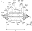
- FIG. 2 illustrates a side view of the balloon of the balloon catheter shown in FIG. 2 illustrates a side view of the shaft at the distal region of the balloon catheter shown in FIG. 1.
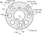
- 4 shows a cross-sectional view of the shaft shown in FIG. 3 taken along line IV-IV.
- 2 illustrates a side view of the shaft at the proximal region of the balloon catheter shown in FIG. 1.
- 6 shows a cross-sectional view of the shaft shown in FIG. 5 taken along the line VI-VI.
- the balloon catheter according to an embodiment of the present invention has a shaft extending in the longitudinal direction from the proximal side to the distal side and a number of balloons arranged in the distal portion of the shaft.
- the shaft In a cross section perpendicular to the longitudinal direction at the distal end of the shaft, the shaft has an inner lumen and a lumen group consisting of a number of outer lumen arranged in a line around the circumferential direction of the inner lumen outside the inner lumen.
- the lumen group includes a first outer lumen, a second outer lumen arranged adjacent to the first outer lumen in the circumferential direction of the inner lumen, and a third outer lumen arranged adjacent to the first outer lumen in the circumferential direction of the inner lumen and on the opposite side to the second outer lumen.
- the shaft has a portion where the distance between the center of the first outer lumen and the center of the second outer lumen is greater than the distance between the center of the first outer lumen and the center of the third outer lumen.
- Fig. 1 is a side view of a balloon catheter according to an embodiment of the present invention
- Fig. 2 is a side view of a balloon of the balloon catheter shown in Fig. 1.
- Fig. 3 is a side view of the shaft in the distal region of the balloon catheter shown in Fig. 1
- Fig. 4 is a IV-IV cross-sectional view of the shaft shown in Fig. 3, showing a cross-sectional view perpendicular to the longitudinal direction of the shaft.
- Fig. 5 is a side view of the shaft in the proximal region of the balloon catheter shown in Fig. 1
- Fig. 6 is a VI-VI cross-sectional view of the shaft shown in Fig. 5, showing a cross-sectional view perpendicular to the longitudinal direction of the shaft.
- the balloon catheter 1 has a shaft 10 that extends longitudinally from the proximal side to the distal side, and a number of balloons 20 arranged in the distal portion of the shaft 10.
- the shaft 10 has a longitudinal direction x1, a radial direction y1 connecting the centroid of the outer edge of the shaft 10 to a point on the outer edge in a cross section perpendicular to the longitudinal direction x1, and a circumferential direction z1 along the outer edge of the shaft 10 in a cross section perpendicular to the longitudinal direction x1.
- the direction toward the user's hand in the longitudinal direction x1 is referred to as the proximal side
- the opposite side to the proximal side i.e., the direction toward the subject of treatment
- Members and parts other than the shaft 10 also have longitudinal, radial, and circumferential directions, which may or may not be the same as the longitudinal direction x1, radial direction y1, and circumferential direction z1 of the shaft 10. However, for ease of understanding, this specification will be described as assuming that all members and parts have the same longitudinal, radial, and circumferential directions as the longitudinal direction x1, radial direction y1, and circumferential direction z1 of the shaft 10.
- the balloon 20 is connected to the distal portion of the shaft 10.
- the balloon 20 can be expanded by introducing fluid through the inner cavity of the shaft 10, and can be deflated by discharging the fluid.
- the fluid can be introduced or discharged using an indeflator (a balloon pressurizer).
- the fluid used may be, for example, saline or a mixture of a contrast agent and saline.
- the fluid may be a pressurized fluid pressurized by a pump or the like.
- Examples of materials that can be used to form the balloon 20 include polyamide resins such as nylon 11 and nylon 12, polyester resins such as polyethylene terephthalate and polybutylene terephthalate, polyurethane resins, and thermoplastic elastomers such as polyether block amide copolymers.
- each of the multiple balloons 20 may be different, but are preferably the same. In other words, it is preferable that each of the multiple balloons 20 is made of the same material. By making each of the multiple balloons 20 out of the same material, it becomes possible to make the degree of expansion and hardness, etc., of the balloons 20 about the same in the circumferential direction z1 of the balloons 20.
- the maximum outer diameters of the multiple balloons 20 may be different, but are preferably the same. Having the same maximum outer diameter of the multiple balloons 20 means that the maximum outer diameters of the multiple balloons 20 are approximately the same, and specifically means that the maximum outer diameter of one balloon 20 is 90% to 110% of the maximum outer diameter of all the other balloons 20. In the expanded state of the balloons 20, having the same maximum outer diameter of the multiple balloons 20 makes it easier to align the timing of expansion of all the balloons 20, and makes it easier to control the expansion of the balloons 20.
- the expanded state of the balloons 20 means that a fluid is introduced into the inner cavity of each of the multiple balloons 20, and all the balloons 20 are expanded.
- the multiple balloons 20 preferably have a first balloon 21 and multiple second balloons 22 arranged outside the first balloon 21 and in a line in the circumferential direction of the first balloon 21.
- the multiple balloons 20 preferably have a first balloon 21 and multiple second balloons 22, and the multiple second balloons 22 are preferably arranged along the outer periphery of the first balloon 21.
- the number of first balloons 21 may be multiple, but is preferably one. In other words, it is preferable that the balloon catheter 1 has one first balloon 21 and multiple second balloons 22. By having only one first balloon 21, the first balloon 21 is less likely to move inside the multiple second balloons 22 when the balloon 20 is in an expanded state. As a result, the first balloon 21 is more likely to suppress the expansion of the multiple second balloons 22, and the hardness of the balloon 2 is increased, making it easier to increase the expansion force.
- the number of second balloons 22 is preferably 3 or more, more preferably 4 or more, and even more preferably 5 or more. By setting the lower limit of the number of second balloons 22 within the above range, the positions of the first balloon 21 and the second balloon 22 are less likely to shift when the balloon 20 is in an expanded state, and the expansion force of the balloon 20 can be increased. In addition, the number of second balloons 22 is preferably 20 or less, more preferably 12 or less, even more preferably 10 or less, and particularly preferably 8 or less. By setting the upper limit of the number of second balloons 22 within the above range, the outer diameter of the balloon 20 portion is less likely to become excessively large, and the minimal invasiveness of the balloon catheter 1 can be improved.
- the respective lengths from the distal end 20d of the balloon 20 to the proximal end 20p of the balloon 20 in the longitudinal direction x1 may be the same or different.
- the respective lengths L2 from the distal end 20d of the second balloon 22 to the proximal end 20p of the second balloon 22 in the longitudinal direction x1 may be different, but are preferably the same.
- the respective lengths L2 from the distal end 20d to the proximal end 20p of the second balloon 22 in the longitudinal direction x1 being the same means that the respective lengths L2 in the longitudinal direction x1 of the multiple second balloons 22 are approximately the same, specifically, the length L2 in the longitudinal direction x1 of one second balloon 22 is 90% or more and 110% or less of the lengths L2 in the longitudinal direction x1 of all the other second balloons 22.
- the balloon 20 preferably has a straight tube section 203, a proximal tapered section 202 located proximal to the straight tube section 203, a proximal sleeve section 201 located proximal to the proximal tapered section 202, a distal tapered section 204 located distal to the straight tube section 203, and a distal sleeve section 205 located distal to the distal tapered section 204.
- the straight tube portion 203 is preferably substantially cylindrical with approximately the same diameter in the longitudinal direction x1, but may have different diameters in the longitudinal direction x1.
- the proximal taper portion 202 and the distal taper portion 204 are preferably formed into a substantially conical or truncated conical shape with a reduced diameter as they move away from the straight tube portion 203.
- the straight tube portion 203 has the maximum diameter, so that when the balloon 20 is expanded at a lesion such as a stenosis, the straight tube portion 203 of the balloon 20 can be in sufficient contact with the lesion, making it easier to treat the lesion by expanding it.
- proximal taper portion 202 and the distal taper portion 204 are reduced in diameter, so that when the balloon 20 is deflated, the outer diameters of the proximal and distal ends of the balloon 20 can be reduced to reduce the step between the shaft 10 and the balloon 20. Therefore, when the balloon 20 is deflated, the outer surface of the balloon catheter 1 becomes smooth, making it easier to insert the balloon catheter 1 into a body cavity.
- the proximal tapered section 202, the straight tube section 203, and the distal tapered section 204 are sections that expand when a fluid is introduced into the balloon 20, whereas the proximal sleeve section 201 and the distal sleeve section 205 are preferably sections that do not expand.
- the proximal sleeve section 201 and the distal sleeve section 205 are preferably sections that do not expand.
- the shaft 10 has an inner lumen 150 and a lumen group 600 composed of a plurality of outer lumen 160 arranged side by side in the circumferential direction z1 of the inner lumen 150 outside the inner lumen 150.
- the inner lumen 150 is a lumen disposed inside the lumen group 600 composed of multiple outer lumen 160 in a cross section perpendicular to the longitudinal direction x1 at the distal end 10d of the shaft 10.
- the inner lumen 150 does not have to be located inside the lumen group 600 at a location other than the distal end 10d of the shaft 10, such as the proximal end 10p of the shaft 10 or the center of the shaft 10 in the longitudinal direction x1, and the lumen located inside the lumen group 600 at the distal end 10d of the shaft 10 is referred to as the inner lumen 150.
- the balloon catheter 1 shows a so-called rapid exchange type balloon catheter 1 having a guidewire port 50 on the way from the distal side to the proximal side of the shaft 10 and a guidewire tube 40 that functions as a guidewire insertion passage from the guidewire port 50 to the distal side of the shaft 10.
- the balloon catheter 1 preferably has a distal shaft 15 and a proximal shaft 16, and the distal shaft 15 and the proximal shaft 16 may be separate members, and the proximal end of the distal shaft 15 may be connected to the distal end of the proximal shaft 16 to form the shaft 10 that extends from the balloon 20 to the proximal end of the balloon catheter 1.
- one shaft 10 may extend from the balloon 20 to the proximal end of the balloon catheter 1, and the distal shaft 15 and the proximal shaft 16 may be further composed of multiple tube members.
- the shaft 10 is preferably made of a resin, a metal, or a combination of a resin and a metal.
- a resin as the material for the shaft 10
- a metal as the material for the shaft 10
- the deliverability of the balloon catheter 1 can be improved.
- resins that make up the shaft 10 include polyamide resins, polyester resins, polyurethane resins, polyolefin resins, fluorine resins, vinyl chloride resins, silicone resins, natural rubber, synthetic rubber, etc. These may be used alone or in combination of two or more types.
- Examples of metals that make up the shaft 10 include stainless steels such as SUS304 and SUS316, platinum, nickel, cobalt, chromium, titanium, tungsten, gold, Ni-Ti alloys, Co-Cr alloys, and combinations thereof.
- the shaft 10 is composed of a distal shaft 15 and a proximal shaft 16 that are separate members, the distal shaft 15 may be made of resin, and the proximal shaft 16 may be made of metal, for example.
- the shaft 10 may also have a layered structure made of different materials or the same material.
- the balloon 20 and the shaft 10 can be joined by bonding with an adhesive, welding, or by attaching a ring-shaped member to the overlapping portion of the end of the balloon 20 and the shaft 10 and crimping the end. Of these, it is preferable that the balloon 20 and the shaft 10 are joined by welding. By joining the balloon 20 and the shaft 10 by welding, the bond between the balloon 20 and the shaft 10 is unlikely to come undone even if the balloon 20 is repeatedly expanded or contracted, and the bond strength can be improved.
- a hub 5 may be provided on the proximal side of the shaft 10.
- the hub 5 may also be provided with a fluid injection section 6 that is connected to a flow path for fluid to be supplied to the inside of the balloon 20.
- the shaft 10 and the hub 5 can be joined by, for example, bonding with an adhesive, welding, etc. Among these, it is preferable that the shaft 10 and the hub 5 are joined by adhesion. By joining the shaft 10 and the hub 5 by adhesion, the bond strength between the shaft 10 and the hub 5 can be increased and the durability of the balloon catheter 1 can be improved when the materials constituting the shaft 10 and the hub 5 are different, for example, when the shaft 10 is made of a highly flexible material and the hub 5 is made of a highly rigid material.
- the inner lumen 150 and the outer lumen 160 extend in the longitudinal direction x1.
- the cross-sectional area of the inner lumen 150 is preferably larger than the cross-sectional area of the outer lumen 160.
- the cross-sectional area of the inner lumen 150 is preferably 1.5 times or more, more preferably 2.0 times or more, and even more preferably 2.5 times or more, the cross-sectional area of the outer lumen 160.
- the cross-sectional area of the inner lumen 150 is preferably 10 times or less, more preferably 9 times or less, and even more preferably 8 times or less, the cross-sectional area of the outer lumen 160.
- the cross-sectional areas of the multiple outer lumens 160 constituting the lumen group 600 may be different, but are preferably the same.
- the cross-sectional areas of the multiple outer lumens 160 constituting the lumen group 600 being the same means that the cross-sectional areas of the multiple outer lumens 160 constituting the lumen group 600 are approximately the same, and specifically, the cross-sectional area of one outer lumen 160 is 90% to 110% of the cross-sectional areas of all the other outer lumens 160.
- the rigidity of the shaft 10 in the circumferential direction z1 becomes approximately the same, and the flexibility of the shaft 10 in the circumferential direction z1 becomes likely to become approximately the same.
- the lumen group 600 in a cross section perpendicular to the longitudinal direction x1 at the distal end 10d of the shaft 10, includes a first outer lumen 161, a second outer lumen 162 arranged adjacent to the first outer lumen 161 in the circumferential direction z1 of the inner lumen 150, and a third outer lumen 163 arranged adjacent to the first outer lumen 161 in the circumferential direction z1 of the inner lumen 150 and on the opposite side of the second outer lumen 162.
- the lumen group 600 includes the first outer lumen 161, the second outer lumen 162 arranged on one side of the circumferential direction z1 of the inner lumen 150 relative to the first outer lumen 161, and the third outer lumen 163 arranged on the other side of the circumferential direction z1 of the inner lumen 150 relative to the first outer lumen 161.
- the second outer lumen 162, the first outer lumen 161, and the third outer lumen 163 are arranged in this order toward one side in the circumferential direction z1 of the inner lumen 150.
- the shaft 10 in a cross section perpendicular to the longitudinal direction x1, has a portion where the distance D20 between the center C161 of the first outer lumen 161 and the center C162 of the second outer lumen 162 is greater than the distance D21 between the center C161 of the first outer lumen 161 and the center C163 of the third outer lumen 163.
- the center C161 of the first outer lumen 161 in a cross section perpendicular to the longitudinal direction x1 refers to the centroid of the outer edge of the cross-sectional shape of the first outer lumen 161.
- the center C162 of the second outer lumen 162 in a cross section perpendicular to the longitudinal direction x1 refers to the centroid of the outer edge of the cross-sectional shape of the second outer lumen 162
- the center C163 of the third outer lumen 163 in a cross section perpendicular to the longitudinal direction x1 refers to the centroid of the outer edge of the cross-sectional shape of the third outer lumen 163.
- the shaft 10 has a portion in which the distance D20 between the center C161 of the first outer inner lumen 161 and the center C162 of the second outer inner lumen 162 is greater than the distance D21 between the center C161 of the first outer inner lumen 161 and the center C163 of the third outer inner lumen 163.
- This allows the distance between the first outer inner lumen 161 and the second outer inner lumen 162 in the circumferential direction z1 of the inner lumen 150 to be greater than the distance between the first outer inner lumen 161 and the third outer inner lumen 163 in the circumferential direction z1 of the inner lumen 150.
- the thickness of the shaft 10 in the portion between the first outer lumen 161 and the second outer lumen 162 can be increased more than the thickness of the shaft 10 in the portion between the first outer lumen 161 and the third outer lumen 163, thereby increasing the rigidity of the portion of the shaft 10 between the first outer lumen 161 and the second outer lumen 162. Since the shaft 10 has a certain section of this thickened portion with high rigidity in the longitudinal direction x1, the force applied from the proximal side of the shaft 10 is easily transmitted to the distal end 10d of the shaft 10, and the balloon catheter 1 can have a good force transmission rate.
- the distance D20 between the center C161 of the first outer lumen 161 and the center C162 of the second outer lumen 162 is preferably 1.5 times or more, more preferably 1.7 times or more, and even more preferably 2.0 times or more, of the distance D21 between the center C161 of the first outer lumen 161 and the center C163 of the third outer lumen 163.
- the thickness of the shaft 10 in the portion between the first outer lumen 161 and the second outer lumen 162 is likely to be thick, and the rigidity of the shaft 10 is likely to be increased.
- the distance D20 between the center C161 of the first outer lumen 161 and the center C162 of the second outer lumen 162 is preferably 10 times or less, more preferably 7 times or less, and even more preferably 5 times or less, of the distance D21 between the center C161 of the first outer lumen 161 and the center C163 of the third outer lumen 163.
- the outer diameter of the shaft 10 is unlikely to become too large, and the low invasiveness of the balloon catheter 1 can be improved.
- the shaft 10 preferably has a portion in which the distance D20 between the center C161 of the first outer lumen 161 and the center C162 of the second outer lumen 162 is greater than the major axis of the outer lumen 160 constituting the lumen group 600.
- the shaft 10 By having a portion in which the distance D20 between the center C161 of the first outer lumen 161 and the center C162 of the second outer lumen 162 is greater than the major axis of the outer lumen 160 constituting the lumen group 600, it becomes easier to greatly increase the distance between the first outer lumen 161 and the second outer lumen 162 in the circumferential direction z1 of the inner lumen 150.
- the thickness of the shaft 10 in the portion between the first outer lumen 161 and the second outer lumen 162 is increased, which increases the rigidity of the shaft 10 and improves the force transmission.
- the distance D20 between the center C161 of the first outer lumen 161 and the center C162 of the second outer lumen 162 is preferably 1.1 times or more, more preferably 1.2 times or more, and even more preferably 1.3 times or more, of the major axis of the outer lumen 160 constituting the lumen group 600.
- the distance D20 between the center C161 of the first outer lumen 161 and the center C162 of the second outer lumen 162 is preferably 5.0 times or less, more preferably 4.5 times or less, and even more preferably 4.0 times or less, of the major axis of the outer lumen 160 constituting the lumen group 600.
- the shaft 10 has a distal region A3, which is a region on the distal side, and a proximal region A4, which is a region located more proximal than the distal region A3.
- the distal region A3 includes the distal end 10d of the shaft 10, and is preferably 1/30 or more of the length in the longitudinal direction x1 from the distal end 10d of the shaft 10 to the proximal end 10p of the shaft 10, and is a region extending from the distal end 10d of the shaft 10 toward the proximal side, more preferably 1/20 or more of the length in the longitudinal direction x1 from the distal end 10d of the shaft 10 to the proximal end 10p of the shaft 10, and is more preferably 1/10 or more of the length in the longitudinal direction x1 from the distal end 10d of the shaft 10 to the proximal end 10p of the shaft 10, and is even more preferably 1/10 or more of the length in the longitudinal direction x1 from the distal end 10d of the shaft 10 to the proximal end 10p of the shaft 10, and is a region extending from the distal end 10d of the shaft 10 toward the proximal side.
- the proximal region A4 is located more proximal than the distal region A3, and is preferably an area that is 1/50 or more of the length in the longitudinal direction x1 from the distal end 10d of the shaft 10 to the proximal end 10p of the shaft 10, more preferably an area that is 1/30 or more of the length in the longitudinal direction x1 from the distal end 10d of the shaft 10 to the proximal end 10p of the shaft 10, and even more preferably an area that is 1/20 or more of the length in the longitudinal direction x1 from the distal end 10d of the shaft 10 to the proximal end 10p of the shaft 10.
- the distal region A3 includes the distal end 15d of the distal shaft 15, and is preferably at least 1/30 of the length in the longitudinal direction x1 from the distal end 15d of the distal shaft 15 to the proximal end 15p of the distal shaft 15, or the region from the distal end 15d of the distal shaft 15 toward the proximal side, more preferably at least 1/20 of the length in the longitudinal direction x1 from the distal end 15d of the distal shaft 15 to the proximal end 15p of the distal shaft 15, or the region from the distal end 15d of the distal shaft 15 toward the proximal side, and even more preferably at least 1/10 of the length in the longitudinal direction x1 from the distal end 15d of the distal shaft 15 to the proximal end 15p of the distal shaft 15, or the region from the distal end 15d of the distal shaft 15 toward the proximal side.
- the proximal region A4 is located proximal to the distal region A3, includes the proximal end 15p of the distal shaft 15, and is preferably 1/50 or more of the length in the longitudinal direction x1 from the distal end 15d of the distal shaft 15 to the proximal end 15p of the distal shaft 15, or a region extending from the proximal end 15p of the distal shaft 15 toward the distal side, more preferably 1/30 or more of the length in the longitudinal direction x1 from the distal end 15d of the distal shaft 15 to the proximal end 15p of the distal shaft 15, or a region extending from the proximal end 15p of the distal shaft 15 toward the distal side, and even more preferably 1/20 or more of the length in the longitudinal direction x1 from the distal end 15d of the distal shaft 15 to the proximal end 15p of the distal shaft 15, or a region extending from the proximal end 15p of the distal shaft 15 toward the distal
- the distance D20 between the center C161 of the first outer lumen 161 and the center C162 of the second outer lumen 162 is greater than the distance D21 between the center C161 of the first outer lumen 161 and the center C163 of the third outer lumen 163.
- the distance D20 between the center C161 of the first outer lumen 161 and the center C162 of the second outer lumen 162 is greater than the distance D21 between the center C161 of the first outer lumen 161 and the center C163 of the third outer lumen 163, so that the distance between the first outer lumen 161 and the second outer lumen 162 in the circumferential direction z1 of the inner lumen 150 can be greater than the distance between the first outer lumen 161 and the third outer lumen 163 in the circumferential direction z1 of the inner lumen 150.
- the thickness of the shaft 10 in the portion between the first outer lumen 161 and the second outer lumen 162 in the circumferential direction z1 of the inner lumen 150 is increased more than the thickness of the shaft 10 in the portion between the first outer lumen 161 and the third outer lumen 163, thereby increasing the rigidity of the portion between the first outer lumen 161 and the second outer lumen 162 of the shaft 10.
- the shaft 10 has this thickened portion with high rigidity in the proximal region A4, and the force applied from the proximal side of the shaft 10 is easily transmitted to the distal end 10d of the shaft 10, making it possible to improve the force transmission of the balloon catheter 1, which has a good force transmission rate.
- the length of the proximal region A4 is equal to or shorter than the length of the distal region A3.
- the length of the highly flexible proximal region A4 and the length of the distal region A3, which has moderate rigidity are balanced throughout the shaft 10, making it possible to obtain a shaft 10 with good insertability.
- the length of the proximal region A4 is shorter than the length of the distal region A3 in the longitudinal direction x1.
- the distance D22 between the center C10 of the shaft 10 and the center C150 of the inner lumen 150 in a cross section perpendicular to the longitudinal direction x1 in the proximal region A4 is greater than the distance D22 between the center C10 of the shaft 10 and the center C150 of the inner lumen 150 in a cross section perpendicular to the longitudinal direction x1 in the distal region A3.
- the position of the center C10 of the shaft 10 in a cross section perpendicular to the longitudinal direction x1 in the distal region A3 coincides with the position of the center C150 of the inner lumen 150, and the distance D22 is 0.
- the distance D22 between the center C10 of the shaft 10 and the center C150 of the inner lumen 150 in the proximal region A4 is greater than the distance D22 between the center C10 of the shaft 10 and the center C150 of the inner lumen 150 in the distal region A3, so that the position of the inner lumen 150 is closer to the outer periphery of the shaft 10 in the proximal region A4 than in the distal region A3.
- the inner lumen 150 is not located inside the lumen group 600 composed of multiple outer lumen 160, and there is an outer lumen 160 located inside the shaft 10 compared to the inner lumen 150.
- the lumen located inside the lumen group 600 composed of multiple outer lumen 160 is the inner lumen 150.
- the distance D22 between the center C10 of the shaft 10 and the center C150 of the inner lumen 150 in a cross section perpendicular to the longitudinal direction x1 increases from the distal end 10d to the proximal end 10p. In other words, it is preferable that the distance D22 between the center C10 of the shaft 10 and the center C150 of the inner lumen 150 in a cross section perpendicular to the longitudinal direction x1 increases from the distal side to the proximal side of the shaft 10.
- the position of the inner lumen 150 approaches the outer periphery of the shaft 10 toward the proximal side. Therefore, the rigidity of the central part of the shaft 10 in a cross section perpendicular to the longitudinal direction x1 of the shaft 10 increases toward the proximal side of the shaft 10, and the shaft 10 becomes less likely to bend on the proximal side of the shaft 10. As a result, the force applied from the proximal end 10p of the shaft 10 is easily transmitted to the distal end 10d of the shaft 10, resulting in a balloon catheter 1 with good force transmission properties.
- the distance D22 between the center C10 of the shaft 10 and the center C150 of the inner lumen 150 in a cross section perpendicular to the longitudinal direction x1 in the proximal region A4 is preferably 1.1 times or more, more preferably 1.2 times or more, and even more preferably 1.3 times or more, of the distance D22 between the center C10 of the shaft 10 and the center C150 of the inner lumen 150 in a cross section perpendicular to the longitudinal direction x1 in the distal region A3.
- the inner lumen 150 can be brought sufficiently closer to the outer periphery of the shaft 10 in the proximal region A4 than in the distal region A3, making it easier to increase the rigidity on the proximal side of the shaft 10.
- the distance D22 between the center C10 of the shaft 10 and the center C150 of the inner lumen 150 in a cross section perpendicular to the longitudinal direction x1 in the proximal region A4 is preferably 15 times or less, more preferably 10 times or less, and even more preferably 5 times or less, of the distance D22 between the center C10 of the shaft 10 and the center C150 of the inner lumen 150 in a cross section perpendicular to the longitudinal direction x1 in the distal region A3.
- the shaft 10 preferably has an opening 170 in the proximal region A4 between adjacent outer lumens 160 in the circumferential direction z1 of the inner lumen 150, which connects the inner lumen 150 to the outside of the shaft 10.
- a region is formed in which the inner lumen 150 approaches the outer surface side of the shaft 10, as shown in FIG. 6.
- the balloon catheter 1 becomes a so-called rapid exchange type, and it becomes easy to introduce items such as a guide wire or fluid into the inner lumen 150 through the opening 170. As a result, it is possible to shorten the procedure time using the balloon catheter 1, and to improve the minimal invasiveness.
- the opening 170 is preferably located in the region between the first outer lumen 161 and the second outer lumen 162 in the circumferential direction z1 of the inner lumen 150.
- the opening 170 is located between the first outer lumen 161 and the second outer lumen 162, which are spaced apart in the circumferential direction z1 of the inner lumen 150. Therefore, when an article such as a guidewire is inserted into the opening 170, the article inserted into the opening 170 is less likely to come into contact with the partition that forms the inner lumen 150, making it less likely that the shaft 10 will be damaged.
- the opening 170 is preferably a guidewire port 50 for inserting a guidewire into the inner lumen 150.
- the balloon catheter 1 of the present invention is preferably a so-called rapid exchange type balloon catheter 1.
- the distance D22 between the center C10 of the shaft 10 and the center C150 of the inner lumen 150 is preferably greater than the shortest distance D23 between the outer edge of the inner lumen 150 and the outer edge of the shaft 10.
- the shortest distance D23 between the outer edge of the inner lumen 150 and the outer edge of the shaft 10 in a cross section perpendicular to the longitudinal direction x1 refers to the length of the shortest straight line connecting a point on the outer edge of the inner lumen 150 and a point on the outer edge of the shaft 10.
- the inner lumen 150 is more likely to be configured close to the outer circumference of the shaft 10 in the proximal region A4. This makes it easier to increase the rigidity of the center of the shaft 10, and makes it easier for the force applied from the proximal side of the shaft 10 to be transmitted to the distal side.
- the distance D22 between the center C10 of the shaft 10 and the center C150 of the inner lumen 150 is preferably 1.1 times or more, more preferably 1.2 times or more, and even more preferably 1.3 times or more, of the shortest distance D23 between the outer edge of the inner lumen 150 and the outer edge of the shaft 10.
- the inner lumen 150 becomes closer to the outer periphery of the shaft 10 in the proximal region A4, and the rigidity of the center of the shaft 10 becomes easier to increase.
- the distance D22 between the center C10 of the shaft 10 and the center C150 of the inner lumen 150 is preferably 10 times or less, more preferably 7 times or less, and even more preferably 5 times or less, of the shortest distance D23 between the outer edge of the inner lumen 150 and the outer edge of the shaft 10.
- the shortest distance D24 between the center C160 of the outer lumen 160 constituting the lumen group 600 and the center C10 of the shaft 10 is greater than the center-to-center distance D25 between adjacent outer lumen 160 in the circumferential direction z1 of the inner lumen 150.
- the shortest distance D24 between the center C160 of the outer lumen 160 and the center C10 of the shaft 10 in a cross section perpendicular to the longitudinal direction x1 refers to the length of the straight line in the outer lumen 160 that is shortest among the straight lines connecting the center C160 of the outer lumen 160 and the center C10 of the shaft 10.
- the shortest distance D24 between the center C160 of the outer lumen 160 and the center C10 of the shaft 10 is greater than the center-to-center distance D25 between adjacent outer lumen 160, which makes it easier for the outer lumen 160 to approach the outer periphery of the shaft 10 and makes it easier to increase the rigidity of the center of the shaft 10.
- the rigidity of the shaft 10 in the proximal region A4 is increased, and the force applied to the shaft 10 from the proximal side to the distal side can be easily transmitted to the distal end 10d of the shaft 10.
- the shortest distance D24 between the center C160 of the outer lumen 160 constituting the lumen group 600 and the center C10 of the shaft 10 is preferably 1.1 times or more, more preferably 1.2 times or more, and even more preferably 1.3 times or more, the center-to-center distance D25 between adjacent outer lumen 160 in the circumferential direction z1 of the inner lumen 150.
- the shortest distance D24 between the center C160 of the outer lumen 160 constituting the lumen group 600 and the center C10 of the shaft 10 is preferably 10 times or less, more preferably 9 times or less, and even more preferably 8 times or less, of the center-to-center distance D25 between adjacent outer lumen 160 in the circumferential direction z1 of the inner lumen 150.
- the outer diameter of the shaft 10 is unlikely to become excessively large, and a balloon catheter 1 that is minimally invasive can be obtained.
- the shortest distance D24 between the center C160 of the outer lumen 160 constituting the lumen group 600 and the center C10 of the shaft 10 is preferably greater than the shortest distance D26 between the outer edge of the outer lumen 160 and the outer edge of the shaft 10.
- the shortest distance D26 between the outer edge of the outer lumen 160 and the outer edge of the shaft 10 in a cross section perpendicular to the longitudinal direction x1 refers to the length of the straight line in the outer lumen 160 that is shortest among the straight lines connecting a point on the outer edge of the outer lumen 160 and a point on the outer edge of the shaft 10.
- the shortest distance D24 between the center C160 of the outer lumen 160 and the center C10 of the shaft 10 is greater than the shortest distance D26 between the outer edge of the outer lumen 160 and the outer edge of the shaft 10, it becomes easier to separate the outer lumen 160 from the center C10 of the shaft 10 in the proximal region A4.
- the rigidity of the center of the shaft 10 in the proximal region A4 tends to increase, making it easier for the force applied from the proximal side of the shaft 10 to be transmitted to the distal side.
- the shortest distance D24 between the center C160 of the outer lumen 160 constituting the lumen group 600 and the center C10 of the shaft 10 is preferably 1.5 times or more, more preferably 2.0 times or more, and even more preferably 2.5 times or more, of the shortest distance D26 between the outer edge of the outer lumen 160 and the outer edge of the shaft 10.
- the shortest distance D24 between the center C160 of the outer lumen 160 constituting the lumen group 600 and the center C10 of the shaft 10 is preferably 20 times or less, more preferably 18 times or less, and even more preferably 15 times or less, of the shortest distance D26 between the outer edge of the outer lumen 160 and the outer edge of the shaft 10.
- the inner lumen 150 is the guidewire lumen 13 through which the guidewire is inserted
- the outer lumen 160 constituting the lumen group 600 is an inflation lumen through which fluid supplied to the lumen of the balloon 20 passes
- each of the lumen of the multiple balloons 20 is connected to each of the lumen of the balloons 20.
- the balloon catheter 1 further includes a guidewire tube 40 having an inner cavity that communicates with the guidewire lumen 13, and the guidewire tube 40 is preferably disposed in the inner cavity of the balloon 20. Since the balloon catheter 1 includes the guidewire tube 40 having an inner cavity that communicates with the guidewire lumen 13, it becomes easy to insert the guidewire into the balloon catheter 1, and it becomes possible to transport the balloon catheter 1 into the body along the guidewire. Furthermore, by inserting the guidewire into the guidewire tube 40, it is possible to prevent the guidewire from damaging the balloon 20, etc.
- the material constituting the guidewire tube 40 may be, for example, a polyolefin resin such as polyethylene or polypropylene, a polyamide resin such as nylon, a polyester resin such as PET, an aromatic polyetherketone resin such as PEEK, a polyetherpolyamide resin, a polyurethane resin, a polyimide resin, a fluorine resin such as PTFE, PFA, or ETFE, or a synthetic resin such as polyvinyl chloride resin.
- the material constituting the guidewire tube 40 is preferably a polyimide resin. By using a polyimide resin as the material constituting the guidewire tube 40, the slipperiness of the guidewire tube 40 is improved.
- the guidewire tube 40 may also have a multi-layer structure including a braided layer such as a metal braid.
- a multi-layer structure for the guidewire tube 40 the strength of the guidewire tube 40, the slipperiness with respect to the guidewire, and the kink resistance can be improved.
- the proximal end of the guidewire tube 40 is preferably connected to the distal end of the shaft 10.
- the shaft 10 has a distal shaft 15 and a proximal shaft 16
- the proximal end of the guidewire tube 40 is preferably connected to the distal end of the distal shaft 15.
- the distal end of the balloon catheter 1 is preferably provided with a tip member 60.
- the tip member 60 may be provided at the distal end of the balloon catheter 1 by being connected to the distal end of the balloon 20 as a separate member from the guidewire tube 40, or the guidewire tube 40 extending distally beyond the distal end 20d of the balloon 20 may function as the tip member 60.
- an X-ray-opaque marker 70 may be placed on the guidewire tube 40 inside the balloon 20 at the location where the balloon 20 is located in the longitudinal axis direction x1 so that the position of the balloon 20 can be confirmed by X-ray fluoroscopy.
- the position on the guidewire tube 40 where the radiopaque marker 70 is arranged may be, for example, the midpoint of the length from the distal end 20d of the balloon 20 to the proximal end 20p of the balloon 20, or the proximal end 203p and distal end 203d of the straight tube portion 203 of the balloon 20.
- the position on the guidewire tube 40 where the radiopaque marker 70 is arranged is preferably the proximal end 203p and distal end 203d of the straight tube portion 203 of the balloon 20.
- the balloon catheter 1 can be made to easily apply pressure to the desired location.
- the shaft 10 has a coating applied to the outer wall of at least one of the distal shaft 15 and the proximal shaft 16, and it is more preferable that the outer wall of both the distal shaft 15 and the proximal shaft 16 are coated.
- the coating applied to the shaft 10 can be a hydrophilic coating or a hydrophobic coating depending on the purpose, and can be applied by immersing the shaft 10 in a hydrophilic coating agent or a hydrophobic coating agent, applying the hydrophilic coating agent or the hydrophobic coating agent to the outer wall of the shaft 10, covering the outer wall of the shaft 10 with the hydrophilic coating agent or the hydrophobic coating agent, etc.
- the coating agent may contain drugs, additives, etc.
- Hydrophilic coating agents include hydrophilic polymers such as polyvinyl alcohol, polyethylene glycol, polyacrylamide, polyvinylpyrrolidone, methyl vinyl ether maleic anhydride copolymer, and hydrophilic coating agents made from any combination thereof.
- Hydrophobic coating agents include polytetrafluoroethylene (PTFE), fluorinated ethylene propylene (FEP), perfluoroalkoxyalkane (PFA), silicone oil, hydrophobic urethane resin, carbon coat, diamond coat, diamond-like carbon (DLC) coat, ceramic coat, and substances with low surface free energy terminated with alkyl groups or perfluoroalkyl groups.
- PTFE polytetrafluoroethylene
- FEP fluorinated ethylene propylene
- PFA perfluoroalkoxyalkane
- silicone oil silicone oil
- hydrophobic urethane resin carbon coat
- diamond coat diamond coat
- DLC diamond-like carbon
- ceramic coat and substances with low surface free energy terminated with alkyl groups or perfluoroalkyl groups.
- the balloon catheter 1 of the present invention is preferably used for expanding an aortic valve, deforming a biological valve placed in the heart, or destroying a biological valve.
- the balloon catheter 1 of the present invention is preferably used for expanding an aortic valve hardened by calcification or the like, and for deforming or destroying an artificial valve ring of a biological valve to replace a deteriorated biological valve placed in the heart.
- the balloon catheter 1 of the present invention has a structure having multiple balloons 20 because the partition between the inner lumen 150 and the outer lumen 160 of the shaft 10 is not easily damaged, and fluids or objects sent to the inner lumen 150 are not easily allowed to enter the outer lumen 160. This makes it easy to expand a hardened aortic valve and deform or destroy a biological valve, which could not be sufficiently expanded with conventional balloon catheters, and is therefore suitable for use.
- Balloon catheter 5 Hub 6: Fluid injection section 10: Shaft 10d: Distal end of shaft 10p: Proximal end of shaft 13: Guidewire lumen 15: Distal shaft 16: Proximal shaft 20: Balloon 20d: Distal end of balloon 20p: Proximal end of balloon 201: Proximal sleeve section 201d: Distal end of proximal sleeve section 201p: Proximal end of proximal sleeve section 202: Proximal taper section 202d: Proximal taper Distal end 202p of proximal taper portion: Proximal end 203 of proximal taper portion: Straight tube portion 203d: Distal end 203p of straight tube portion: Proximal end 204 of straight tube portion: Distal taper portion 204d: Distal end 204p of distal taper portion: Proximal end 205 of distal taper portion: Distal sleeve portion 205
Landscapes
- Health & Medical Sciences (AREA)
- Life Sciences & Earth Sciences (AREA)
- Heart & Thoracic Surgery (AREA)
- Engineering & Computer Science (AREA)
- Biophysics (AREA)
- Pulmonology (AREA)
- Child & Adolescent Psychology (AREA)
- Anesthesiology (AREA)
- Biomedical Technology (AREA)
- Hematology (AREA)
- Animal Behavior & Ethology (AREA)
- General Health & Medical Sciences (AREA)
- Public Health (AREA)
- Veterinary Medicine (AREA)
- Media Introduction/Drainage Providing Device (AREA)
Priority Applications (2)
| Application Number | Priority Date | Filing Date | Title |
|---|---|---|---|
| CN202480039081.8A CN121311271A (zh) | 2023-06-22 | 2024-06-19 | 球囊导管 |
| JP2025528088A JPWO2024262528A1 (https=) | 2023-06-22 | 2024-06-19 |
Applications Claiming Priority (2)
| Application Number | Priority Date | Filing Date | Title |
|---|---|---|---|
| JP2023102819 | 2023-06-22 | ||
| JP2023-102819 | 2023-06-22 |
Publications (1)
| Publication Number | Publication Date |
|---|---|
| WO2024262528A1 true WO2024262528A1 (ja) | 2024-12-26 |
Family
ID=93935410
Family Applications (1)
| Application Number | Title | Priority Date | Filing Date |
|---|---|---|---|
| PCT/JP2024/022199 Ceased WO2024262528A1 (ja) | 2023-06-22 | 2024-06-19 | バルーンカテーテル |
Country Status (3)
| Country | Link |
|---|---|
| JP (1) | JPWO2024262528A1 (https=) |
| CN (1) | CN121311271A (https=) |
| WO (1) | WO2024262528A1 (https=) |
Citations (4)
| Publication number | Priority date | Publication date | Assignee | Title |
|---|---|---|---|---|
| JPH05506174A (ja) * | 1990-09-14 | 1993-09-16 | アメリカン・メディカル・システムズ・インコーポレーテッド | 組み合わせた高熱療法及び拡張カテーテル |
| JP2000279524A (ja) * | 1999-03-30 | 2000-10-10 | Junichi Tanaka | カテーテル |
| JP2012508041A (ja) * | 2008-11-03 | 2012-04-05 | アトランタ・カテーテル・セラピーズ・インコーポレーテッド | 閉塞灌流カテーテル |
| US20120265283A1 (en) * | 2011-04-14 | 2012-10-18 | Mack Matthew M | Reperfusion injury devices |
-
2024
- 2024-06-19 CN CN202480039081.8A patent/CN121311271A/zh active Pending
- 2024-06-19 WO PCT/JP2024/022199 patent/WO2024262528A1/ja not_active Ceased
- 2024-06-19 JP JP2025528088A patent/JPWO2024262528A1/ja active Pending
Patent Citations (4)
| Publication number | Priority date | Publication date | Assignee | Title |
|---|---|---|---|---|
| JPH05506174A (ja) * | 1990-09-14 | 1993-09-16 | アメリカン・メディカル・システムズ・インコーポレーテッド | 組み合わせた高熱療法及び拡張カテーテル |
| JP2000279524A (ja) * | 1999-03-30 | 2000-10-10 | Junichi Tanaka | カテーテル |
| JP2012508041A (ja) * | 2008-11-03 | 2012-04-05 | アトランタ・カテーテル・セラピーズ・インコーポレーテッド | 閉塞灌流カテーテル |
| US20120265283A1 (en) * | 2011-04-14 | 2012-10-18 | Mack Matthew M | Reperfusion injury devices |
Also Published As
| Publication number | Publication date |
|---|---|
| JPWO2024262528A1 (https=) | 2024-12-26 |
| CN121311271A (zh) | 2026-01-09 |
Similar Documents
| Publication | Publication Date | Title |
|---|---|---|
| WO2021049282A1 (ja) | バルーンカテーテルの製造方法 | |
| JP4985398B2 (ja) | カテーテル | |
| WO2020195697A1 (ja) | バルーンカテーテル | |
| WO2020195170A1 (ja) | バルーンカテーテル | |
| JP4914282B2 (ja) | 押圧性を備えたカテーテル | |
| WO2024262528A1 (ja) | バルーンカテーテル | |
| JP2025109390A (ja) | バルーンカテーテル | |
| WO2024262529A1 (ja) | バルーンカテーテル、および該バルーンカテーテルにおけるバルーンの拡張方法 | |
| WO2024262527A1 (ja) | バルーンカテーテル | |
| JP2025002563A (ja) | バルーンカテーテル、および該バルーンカテーテルにおけるバルーンの拡張方法 | |
| JP2025002562A (ja) | バルーンカテーテル | |
| WO2023079906A1 (ja) | バルーンカテーテル用バルーン | |
| WO2024262526A1 (ja) | バルーンカテーテル | |
| WO2025204185A1 (ja) | バルーンカテーテル | |
| US20250152922A1 (en) | Balloon catheter | |
| JP2025147477A (ja) | バルーンカテーテル | |
| WO2025197596A1 (ja) | バルーンカテーテル | |
| WO2025197348A1 (ja) | バルーンカテーテル | |
| JP2025142774A (ja) | バルーンカテーテル | |
| US20250269155A1 (en) | Balloon for balloon catheter and balloon catheter including same | |
| US20260076709A1 (en) | Balloon for balloon catheter and balloon catheter including same | |
| JP7526112B2 (ja) | カテーテル | |
| US20250269153A1 (en) | Balloon for balloon catheter, balloon catheter including same, and method for producing balloon catheter | |
| US20250269151A1 (en) | Balloon for balloon catheter and balloon catheter including same | |
| WO2025197347A1 (ja) | バルーンカテーテル |
Legal Events
| Date | Code | Title | Description |
|---|---|---|---|
| 121 | Ep: the epo has been informed by wipo that ep was designated in this application |
Ref document number: 24825929 Country of ref document: EP Kind code of ref document: A1 |
|
| ENP | Entry into the national phase |
Ref document number: 2025528088 Country of ref document: JP Kind code of ref document: A |
|
| WWE | Wipo information: entry into national phase |
Ref document number: 2025528088 Country of ref document: JP |
|
| WWE | Wipo information: entry into national phase |
Ref document number: CN2024800390818 Country of ref document: CN |
|
| NENP | Non-entry into the national phase |
Ref country code: DE |