WO2024262138A1 - 加工状態推定装置及び加工状態推定方法 - Google Patents
加工状態推定装置及び加工状態推定方法 Download PDFInfo
- Publication number
- WO2024262138A1 WO2024262138A1 PCT/JP2024/014227 JP2024014227W WO2024262138A1 WO 2024262138 A1 WO2024262138 A1 WO 2024262138A1 JP 2024014227 W JP2024014227 W JP 2024014227W WO 2024262138 A1 WO2024262138 A1 WO 2024262138A1
- Authority
- WO
- WIPO (PCT)
- Prior art keywords
- parameter
- state
- estimation
- prediction process
- processing
- Prior art date
- Legal status (The legal status is an assumption and is not a legal conclusion. Google has not performed a legal analysis and makes no representation as to the accuracy of the status listed.)
- Ceased
Links
Images






Classifications
-
- B—PERFORMING OPERATIONS; TRANSPORTING
- B21—MECHANICAL METAL-WORKING WITHOUT ESSENTIALLY REMOVING MATERIAL; PUNCHING METAL
- B21D—WORKING OR PROCESSING OF SHEET METAL OR METAL TUBES, RODS OR PROFILES WITHOUT ESSENTIALLY REMOVING MATERIAL; PUNCHING METAL
- B21D22/00—Shaping without cutting, by stamping, spinning, or deep-drawing
-
- B—PERFORMING OPERATIONS; TRANSPORTING
- B21—MECHANICAL METAL-WORKING WITHOUT ESSENTIALLY REMOVING MATERIAL; PUNCHING METAL
- B21D—WORKING OR PROCESSING OF SHEET METAL OR METAL TUBES, RODS OR PROFILES WITHOUT ESSENTIALLY REMOVING MATERIAL; PUNCHING METAL
- B21D28/00—Shaping by press-cutting; Perforating
-
- B—PERFORMING OPERATIONS; TRANSPORTING
- B21—MECHANICAL METAL-WORKING WITHOUT ESSENTIALLY REMOVING MATERIAL; PUNCHING METAL
- B21D—WORKING OR PROCESSING OF SHEET METAL OR METAL TUBES, RODS OR PROFILES WITHOUT ESSENTIALLY REMOVING MATERIAL; PUNCHING METAL
- B21D28/00—Shaping by press-cutting; Perforating
- B21D28/24—Perforating, i.e. punching holes
- B21D28/34—Perforating tools; Die holders
-
- B—PERFORMING OPERATIONS; TRANSPORTING
- B30—PRESSES
- B30B—PRESSES IN GENERAL
- B30B15/00—Details of, or accessories for, presses; Auxiliary measures in connection with pressing
-
- B—PERFORMING OPERATIONS; TRANSPORTING
- B30—PRESSES
- B30B—PRESSES IN GENERAL
- B30B15/00—Details of, or accessories for, presses; Auxiliary measures in connection with pressing
- B30B15/28—Arrangements for preventing distortion of, or damage to, presses or parts thereof
-
- G—PHYSICS
- G05—CONTROLLING; REGULATING
- G05B—CONTROL OR REGULATING SYSTEMS IN GENERAL; FUNCTIONAL ELEMENTS OF SUCH SYSTEMS; MONITORING OR TESTING ARRANGEMENTS FOR SUCH SYSTEMS OR ELEMENTS
- G05B19/00—Program-control systems
- G05B19/02—Program-control systems electric
- G05B19/18—Numerical control [NC], i.e. automatically operating machines, in particular machine tools, e.g. in a manufacturing environment, so as to execute positioning, movement or co-ordinated operations by means of program data in numerical form
Definitions
- This disclosure relates to a machining state estimation device and a machining state estimation method.
- Patent Document 1 discloses a technique for obtaining a judgment value by combining the state quantities of normal equipment and abnormal equipment in equipment that repeats the same task in a relatively short cycle, such as a press.
- the judgment device in Patent Document 1 generates an alarm when the state quantity of the target equipment exceeds or falls below the judgment value.
- This disclosure provides a machining state estimation device and machining state estimation method that make it easier to estimate the machining state with high accuracy.
- a machining state estimation device is a machining state estimation device that estimates a machining state of a press machine that repeatedly performs press working, a processor that executes a first prediction process and a second prediction process related to estimation of a machining state in a first cycle; a storage device;
- the storage device is First and second parameters defining a processing state of the press; a plurality of reference data each indicating a change in processing load by the press machine corresponding to each combination of the first and second parameters;
- the processor Obtaining measurement data showing the measurement results of the processing load by the press machine; obtaining first and second current state parameters corresponding to the first and second parameters, respectively, which indicate an estimated result of the processing state of the press machine at a predetermined reference time before the measurement of the measurement data;
- the processor fluctuating a first parameter within a predetermined first range from a first current state parameter and fixing a second parameter to a second current state parameter, and searching for reference data that maximizes a similarity, which is an index of
- a machining state estimation method for estimating a machining state of a press machine that repeatedly performs press working, comprising: A step of acquiring measurement data indicating a measurement result of a processing load applied by a press by a processor; A step in which a processor acquires first and second current state parameters corresponding to first and second parameters defining the processing state of the press machine, respectively, which indicate an estimated result of the processing state of the press machine at a predetermined reference time before the measurement of the measurement data; A step of executing a first prediction process and a second prediction process related to estimation of a machining state in a first cycle by a processor; and outputting the estimation results for the first and second parameters by the processor;
- the first prediction process includes: a step of varying a first parameter within a predetermined first range from a first current state parameter and fixing a second parameter to a second current state parameter, and searching for reference data having a maximum similarity, which is an index of the degree of similarity to the measurement
- This disclosure makes it easier to estimate the processing state with high accuracy.
- FIG. 1 is a block diagram showing a configuration example of a machining state estimating device according to an embodiment of the present disclosure.
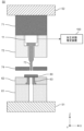
- 2 is a schematic cross-sectional view showing a press machine to which the load sensor shown in FIG. 1 is attached.
- 2 is a schematic graph showing an example of a waveform measured by the load sensor shown in FIG. 1 .
- 2 is a schematic diagram illustrating an overview of a machining state estimation process executed by the machining state estimation device of FIG. 1 ;
- FIG. FIG. 3 is a schematic cross-sectional view for illustrating the area of the punching contour of the press of FIG. 2;
- 13 is a table showing an example of status data.
- FIG. 4 is a flowchart illustrating a procedure of a machining state estimation process executed by a CPU of the machining state estimation device of FIG. 1 .
- 8 is a flowchart illustrating the initial state estimation process shown in FIG. 7 .
- 9 is a flowchart illustrating the clearance and workpiece thickness estimation process shown in FIG. 8 .
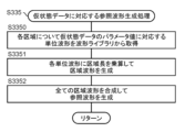
- 10 is a flowchart illustrating a reference waveform generating process corresponding to the state data shown in FIG. 9 .
- 10 is a flowchart illustrating a reference waveform generating process corresponding to the provisional state data shown in FIG. 9 .
- 8 is a flowchart illustrating the progress state estimation process shown in FIG. 7 .
- 13 is a flowchart illustrating the workpiece thickness estimation process shown in FIG. 12 .
- 11 is a graph illustrating a result of a machining state estimation process according to the present embodiment.
- processing state refers to at least one of the amount of wear of a tool, the clearance, and the thickness of a workpiece.
- the load applied to the punch or workpiece during punching depends on the amount of punch wear, the amount of die wear, the clearance, the thickness of the workpiece, etc.
- the amount of punch wear and the amount of die wear are examples of a punch wear parameter, which is an index showing the degree of wear of the punch, and a die wear parameter, which is an index showing the degree of wear of the die, respectively.
- the amount of tool wear such as the amount of punch wear and the amount of die wear, is expressed, for example, as the change in dimensions from the design value of the tool.
- the amount of tool wear may also be expressed as the amount of change, such as a change in shape, volume, or mass.
- the amount of tool wear may also be expressed as the radius of an arc when the wear is approximated as an arc.
- Clearance is the gap between the die and punch.
- clearance is the gap between the die and punch when a hole is punched into a workpiece.
- Clearance may be expressed as the ratio of the gap between the die and punch to the thickness of the workpiece.
- the load depends on these parameters, it is possible to estimate these parameters from the load waveform obtained during processing. For example, if the amount of tool wear, such as punch wear and die wear, can be estimated, it will be possible to know the ideal timing for grinding or re-grinding (hereinafter simply referred to as "grinding") tools in a processing machine that performs cyclic processing. Grinding tools at the ideal timing can prevent situations such as machining workpieces with worn tools and producing a large number of defective products, thereby increasing productivity.
- grinding or re-grinding hereinafter simply referred to as "grinding”
- the inventors discovered that in a processing machine that performs cyclic processing, there is an advantage to using the history of estimated processing state results for punching to estimate the processing state.
- the fluctuations in values for clearance, punch wear, die wear, etc. are gradual compared to fluctuations in the thickness of the workpiece, etc.
- values for clearance, punch wear, die wear, etc. usually do not change significantly from the values in the immediately preceding punching, so in the history of estimated results that show the fluctuations in these values (changes over time or with respect to the number of processing cycles), the fluctuations in these values are gradual and the amount of change is small.
- fluctuations in the thickness of the workpiece can occur even within a short period of time.
- the thickness of the workpiece can change significantly from the value in the previous punching.
- FIG. 1 is a block diagram showing an example of a configuration of a machining state estimating device 100 according to an embodiment of the present disclosure.
- the machining state estimating device 100 includes a CPU 1, a storage device 2, an input interface (I/F) 3, and an output interface (I/F) 4.
- the CPU 1 performs information processing to realize the functions of the machining state estimation device 100 described below. Such information processing is realized, for example, by the CPU 1 operating according to the instructions of a program 21 stored in the storage device 2.
- the CPU 1 is an example of a processor of the present disclosure.
- the processor is not limited to a CPU as long as it includes an arithmetic circuit that performs calculations for information processing.
- the processor may be configured with circuits such as an MPU or FPGA.
- the storage device 2 is a recording medium that records various information including data such as a waveform library 23 and state data 22 described below, and a program 21 required to realize the functions of the machining state estimation device 100.
- the storage device 2 is realized, for example, by a semiconductor storage device such as a flash memory or a solid state drive (SSD), a magnetic storage device such as a hard disk drive (HDD), or other recording media alone or in combination.
- the storage device 2 may include a volatile memory such as an SRAM or a DRAM.
- the input interface 3 is an interface circuit that connects the machining state estimation device 100 to an external device in order to input information such as the detection results by the load sensor 11 to the machining state estimation device 100.
- external devices are, for example, the load sensor 11, other information processing terminals, and other devices.
- the input interface 3 may be a communication circuit that performs data communication according to an existing wired communication standard or wireless communication standard.
- the output interface 4 is an interface circuit that connects the machining state estimation device 100 to an external output device in order to output information from the machining state estimation device 100.
- Such an output device is, for example, a display or another information processing terminal.
- the output interface 4 may be a communication circuit that performs data communication according to an existing wired communication standard or wireless communication standard.
- the input interface 3 and the output interface 4 may be realized by similar hardware.
- FIG. 2 is a schematic cross-sectional view showing a press machine 50 to which the load sensor 11 shown in FIG. 1 is attached.
- FIG. 2 shows an X-axis, a Y-axis, and a Z-axis that are perpendicular to each other.
- the Z-axis indicates the vertical direction.
- the press 50 is an example of a processing machine that performs cyclic processing by repeating the same processing.
- the press 50 is equipped with a bolster 51 and a slide 52 that repeatedly performs a cyclic movement up and down from the top dead center to the bottom dead center relative to the bolster 51.
- a die backing plate 61 is attached on top of the bolster 51, and a die plate 62 is attached on top of the die backing plate 61.
- the die plate 62 holds a die 63.
- a punch backing plate 71 is attached to the bottom of the slide 52, and a punch plate 72 is attached to the bottom of the punch backing plate 71.
- the punch plate 72 grips the punch 73.
- the press 50 further includes a stripper plate 74.
- the stripper plate 74 is attached to a fastener such as a bolt and to the punch plate 72 or punch backing plate 71 via positioning guides such as posts (not shown).
- the stripper plate 74 is biased downward by, for example, a compression spring, and has the function of guiding the position of the punch 73 to be constant, as well as the function of removing material adhering to the punch 73 after punching the workpiece 80, and/or the function of fixing the workpiece 80 when punching the workpiece 80.
- the load sensor 11 is installed, for example, between the punch 73 and the punch backing plate 71.
- the load sensor 11 is, for example, a piezoelectric force sensor or an electric force sensor such as a strain gauge type, and measures the load applied to the punch 73 when the punch 73 punches the workpiece 80.
- FIG. 3 is a schematic graph showing an example of a waveform measured by the load sensor 11.
- the horizontal axis of the graph in FIG. 3 represents time, and the vertical axis represents load.
- the time on the horizontal axis is based (0) on the time when the punch 73 is at the top dead center, which is the initial position.
- the punch 73 moves in the negative direction of the Z axis from the top dead center to the bottom dead center.
- the graph in FIG. 3 shows a mountain-shaped waveform in which, during punching, a load begins to be applied to the workpiece 80, and therefore to the punch 73 and the load sensor 11, from the moment the punch 73 descends and makes contact with the workpiece 80, and the load suddenly decreases to almost zero after the workpiece 80 is punched.
- the punching start timing of the punching process can be measured, for example, based on the time when the load exceeds a rising threshold in the measured waveform.
- a rising threshold may be defined as an absolute value, or as a percentage of the peak value of the load.
- the horizontal axis of the graph may represent the distance that the punch 73 has advanced in the negative direction of the Z axis (the distance advanced is taken as a positive value).
- Figure 4 is a schematic diagram illustrating an example of the outline of the machining state estimation process executed by the machining state estimation device 100 of Figure 1.
- the CPU 1 obtains the unit waveform (hereinafter referred to as "standard reference data") per unit length of the punching contour of the press machine 50 from the waveform library 23, and generates area waveforms (area data) corresponding to the two areas A1 and A2, respectively.
- the CPU 1 synthesizes all the area waveforms to generate a reference waveform (hereinafter referred to as “total reference data"), and compares the measured waveform with the reference waveform.
- the unit waveform, area waveform, and reference waveform are waveform data that indicate the change over time in the processing load applied by the press 50, and can be compared with the measured waveform.
- the unit waveform is associated with a parameter indicating at least one of the tool wear amount, clearance, or workpiece thickness, so that the parameters of each of areas A1 and A2 can be estimated by searching for a reference waveform that closely matches the measured waveform.
- FIG. 5 is a schematic cross-sectional view for explaining areas A1 and A2 of the punching contour of the press 50.
- the cross-sectional view of FIG. 5 shows only the punch 73 and the die 63 to facilitate understanding of the explanation.
- the punching contour is the contour of the portion of the workpiece 80 that is punched by the punching process using the press machine 50.
- the shapes of the punch 73 and the die 63 are designed to achieve the desired punching contour.
- the punching contour may be the design value of the contour of the punch 73 as viewed from the punching direction, or the design value of the contour of the opening of the die 63 as viewed from the punching direction.
- Areas A1 and A2 of the punched contour are obtained by dividing the punched contour. Where the punched contour is divided is determined in advance according to the shape of the punched contour. In the example of FIG. 5, the punched contour is a rectangle with rounded corners. Areas A1 and A2 of the punched contour are obtained by dividing the punched contour. In the example of FIG. 5, the punched contour is divided into two, and one of the divided punched contours is area A1, and the other is area A2.
- FIG. 6 is a table showing an example of status data 22.
- Status data 22 includes a profile parameter that defines information about the punching profile, a tool status parameter that defines the status of the tool, and a work status parameter that defines the status of the work.
- the profile parameter is the zone length along the punching profile.
- the tool status parameters are punch wear amount, die wear amount, and clearance.
- the work status parameter is the work thickness.
- the contour parameters shown in FIG. 6 are an example of the "area shape information" of the present disclosure.
- the area lengths of the first area A1 and the second area A2 are represented as W1 and W2, respectively.
- the punch wear amount, die wear amount, and clearance in the first area A1 are represented as P1, D1, and C1, respectively
- the punch wear amount, die wear amount, and clearance in the second area A2 are represented as P2, D2, and C2, respectively.
- the workpiece thickness T is constant across the entire region.
- this embodiment is not limited to this, and the workpiece thickness may take different values for each region, similar to the amount of punch wear, the amount of die wear, and the clearance.
- punch wear amounts P1 and P2 can be set to any of the candidate values of 0 ⁇ m, 2 ⁇ m, 4 ⁇ m, 6 ⁇ m, 8 ⁇ m, 10 ⁇ m, and 12 ⁇ m.
- die wear amounts D1 and D2 can be set to any of the candidate values of 0 ⁇ m, 2 ⁇ m, 4 ⁇ m, 6 ⁇ m, 8 ⁇ m, 10 ⁇ m, and 12 ⁇ m.
- clearances C1 and C2 can be set to any of the candidate values of 3 ⁇ m, 4 ⁇ m, 5 ⁇ m, 6 ⁇ m, and 7 ⁇ m.
- work thickness T can be set to any of the candidate values of 46 ⁇ m, 48 ⁇ m, 50 ⁇ m, 52 ⁇ m, and 54 ⁇ m.
- candidate values of punch wear amount, die wear amount, clearance, and work thickness are not limited to these, and the number of candidate values is not limited to the above number.
- the waveform library 23 is a four-dimensional table in which unit waveforms corresponding to the arrays of punch wear amount, die wear amount, clearance, and workpiece thickness are registered.
- unit waveforms per unit length of the punching contour corresponding to all combinations of punch wear amount, die wear amount, clearance, and work thickness are registered in advance.
- the unit length is a predetermined unit length, for example, 1 mm.
- the unit waveform is a waveform that represents the relationship between time and load, similar to the measured waveform in Figure 3.
- the unit waveform can be obtained, for example, by actually measuring the punching load or by multiplying the waveform obtained by simulation by the ratio of the unit length to the total length of the punching contour. For example, if the unit length is 1 [mm] and the total length of the punching contour is L [mm], the unit waveform can be obtained by actually measuring the punching load or by multiplying the waveform obtained by simulation by 1/L.
- CPU 1 obtains unit waveforms corresponding to the combination of punch wear amount, die wear amount, clearance, and work thickness for each zone from waveform library 23. Next, CPU 1 generates a zone waveform for each zone by multiplying each unit waveform by the zone length. As shown in Figure 6, CPU 1 generates a reference waveform that indicates the load over the entire length of the punching contour by combining two zone waveforms.
- the CPU 1 searches for a reference waveform that has the highest degree of match with the measured waveform, and estimates the combination of parameters corresponding to the unit waveform of each area that is the basis of the searched reference waveform as an estimated parameter set that represents the machining state of that area.
- Fig. 7 is a flow chart illustrating the procedure of the machining state estimation process executed by the CPU 1 of the machining state estimation device 100 of Fig. 1. The process of Fig. 7 is performed every time the CPU 1 acquires a measurement waveform from the load sensor 11. For example, the execution interval of the process of Fig. 7 is approximately equal to the machining period of the cycle machining.
- the CPU 1 acquires from the load sensor 11 a measurement waveform that indicates the measurement result of the load applied to the load sensor 11 during press processing by the press machine 50 (S1).
- CPU1 determines whether a predetermined period of time has elapsed since the tool was replaced (S2). For example, CPU1 determines whether a predetermined period of time has elapsed since it received a tool replacement signal indicating that a tool was replaced. CPU1 may determine that a predetermined period of time has elapsed if press processing has been performed a predetermined number of times or more since it received the tool replacement signal. Such a tool replacement signal is transmitted to CPU1, for example, by a user pressing a tool replacement completion button provided on the press machine 50, the user interface of the machining state estimation device 100, etc.
- the CPU 1 executes a first state estimation process (hereinafter referred to as the "initial state estimation process") S3. Details of the initial state estimation process S3 will be described later.
- step S2 If it is determined in step S2 that a predetermined period of time has elapsed since the tool was replaced (Yes in S2), the CPU 1 executes a second state estimation process (hereinafter referred to as the "progress state estimation process") S4. Details of the progress state estimation process S4 will be described later.
- FIG. 8 is a flowchart illustrating the initial state estimation process S3 shown in FIG.
- the CPU 1 acquires state data 22 estimated in the previous processing state estimation process (S31).
- step S31 if there is no previously estimated state data 22, the CPU 1 creates state data 22 and sets parameters to initial values. For example, the initial value of the punch wear amount is 0 ⁇ m, the initial value of the die wear amount is 0 ⁇ m, the initial value of the clearance is 5 ⁇ m, and the initial value of the work thickness is 50 ⁇ m.
- step S32 if the punch 73 has been replaced or re-ground, the punch wear amount is set to an initial value of 0 ⁇ m. Similarly, if the die 63 has been replaced or re-ground, the die wear amount is set to an initial value of 0 ⁇ m.
- the CPU 1 executes a clearance and workpiece thickness estimation process (S33).
- the clearance and workpiece thickness estimation process S33 the clearance and workpiece thickness are estimated.
- FIG. 9 is a flow chart illustrating the clearance and workpiece thickness estimation process S33 shown in FIG. 8.
- the CPU 1 first executes a reference waveform generation process S331 that corresponds to the status data.
- FIG. 10 is a flow chart illustrating the reference waveform generation process S331 corresponding to the state data shown in FIG. 9.
- the CPU 1 obtains unit waveforms corresponding to the parameter values of the state data 22 for each area from the waveform library 23 (S3310).
- CPU 1 generates a segment waveform for each segment by multiplying each unit waveform by the segment length (S3311).
- the CPU 1 generates a reference waveform that indicates the load over the entire length of the punching contour by synthesizing all the area waveforms (S3312). Synthesizing multiple waveforms means, for example, taking the sum of multiple waveforms.
- the CPU 1 calculates the degree of match between the reference waveform corresponding to the status data 22 generated in step S331 and the measurement waveform acquired in step S1 (S332).
- the degree of agreement is an index showing the degree of agreement between two waveforms.
- the degree of agreement is, for example, the cosine similarity, Euclidean distance, or Manhattan distance between two waveforms during the punching period.
- the CPU 1 may calculate a loss, which is an index showing the degree of mismatch between two waveforms.
- Both the degree of agreement and the degree of mismatch are examples of "similarity,” which is an index showing the degree of similarity between two waveforms.
- CPU1 judges whether the loop processing in the clearance and workpiece thickness estimation processing S33 has converged (completed) (S333).
- Convergence means that all candidate values that can be selected based on a predetermined selection rule have been set in all areas of the provisional state data.
- CPU1 judges whether all candidate values for combinations of clearance and workpiece thickness have been set as the clearance and workpiece thickness in areas A1 and A2 of the provisional state data, as a convergence judgment.
- step S333 the CPU 1 determines whether the loop processing has converged based on whether all candidate values have been set, but the present disclosure is not limited to this.
- the CPU 1 may determine whether the loop processing has converged based on the provisional state data in step S334 and the change in the degree of agreement in step S336.
- step S333 determines in step S333 that the loop processing in the clearance and workpiece thickness estimation processing S33 has not converged (No in S333), it executes step S334, and if it determines that the loop processing has converged (Yes in S333), it ends the clearance and workpiece thickness estimation processing S33.
- step S334 the CPU 1 prepares provisional state data by modifying the state data 22 for each area so that the clearance and the workpiece thickness are set to one of the candidate values for the clearance and the workpiece thickness (S334). Note that in step S334, the other parameters of the provisional state data, the punch wear amount and the die wear amount, are fixed to the previously estimated punch wear amount and die wear amount, respectively.
- CPU1 executes the reference waveform generation process S335 corresponding to the provisional state data.
- FIG. 11 is a flow chart illustrating the reference waveform generation process S335 corresponding to the provisional state data shown in FIG. 9. Compared to the reference waveform generation process S331 corresponding to the state data in FIG. 10, the reference waveform generation process S335 corresponding to the provisional state data includes step S3350 instead of step S3310.
- the CPU 1 first obtains unit waveforms corresponding to the parameter values of the provisional state data for each area from the waveform library 23 (S3350).
- the subsequent steps S3351 and S3352 are similar to steps S3311 and S3312, respectively, of the reference waveform generation process S331 corresponding to the state data in FIG. 10.
- the CPU 1 calculates the degree of match between the reference waveform corresponding to the provisional state data generated in step S335 and the measurement waveform acquired in step S1 (S336).
- the CPU 1 determines whether the degree of match calculated in step S336 has increased compared to the degree of match calculated in the most recent step S332 (S337). If the CPU 1 determines that the degree of match has increased (Yes in S337), it proceeds to step S338, and if the CPU 1 determines that the degree of match has not increased (No in S337), it returns to step S333.
- step S3308 the CPU 1 updates the state data 22 so that the provisional state data prepared in step S334 becomes the state data 22 (S338). After completing step S338, the CPU 1 returns to step S331.
- step S333 if the CPU 1 determines in step S333 that the loop processing in the clearance and workpiece thickness estimation processing S33 has converged (Yes in S333), it ends the clearance and workpiece thickness estimation processing S33.
- CPU1 may set the clearances in areas A1 and A2 of the provisional state data to 3 ⁇ m, 4 ⁇ m, 5 ⁇ m, 6 ⁇ m, and 7 ⁇ m, and the work thicknesses to 46 ⁇ m, 48 ⁇ m, 50 ⁇ m, 52 ⁇ m, and 54 ⁇ m. Furthermore, the set values in areas A1 and A2 may be different from each other.
- CPU1 has completed all loops corresponding to all combinations of the clearance set values and the work thickness set values, it ends the clearance and work thickness estimation process S33.
- the CPU 1 updates the current state data and the progress state data (S34).
- the current state data is an example of the first state data (see FIG. 12).
- the progress state data is an example of the second to seventh state data (see FIG. 12).
- the CPU 1 prepares state data (first to seventh state data) to be used in prediction flows F1 to F7 of the progress state estimation process S4, which will be described later.
- tool condition parameters change as wear progresses, but the degree of change is gradual compared to the workpiece thickness.
- the amount of punch wear and die wear gradually increases as the cycle processing progresses.
- press processing it is known that the side surface is gradually worn away due to friction generated between the punch 73 and the workpiece 80, and the clearance at the tip where the punch 73 contacts the workpiece 80 also gradually increases as the cycle processing progresses.
- step S34 the CPU 1 prepares multiple pieces of progress status data (second to seventh status data) in addition to the status data 22 (current status data, first status data) predicted in the clearance and workpiece thickness estimation process S33.
- Each progress state data is prepared by carrying out a process for changing the punch wear amount, die wear amount, and/or clearance in the current state data to a value one step larger than the current state data.
- the state data 22 itself predicted in the clearance and workpiece thickness estimation process S33 is used as the first state data corresponding to prediction flow F1.
- state data in which at least one parameter is different from the first state data is used.
- the punch wear amount P1 in the first area A1 is set to 2 ⁇ m, which is one step larger than 0 ⁇ m.
- the punch wear amount P1 in the second area A2 is set to 2 ⁇ m.
- the die wear amount D1 in area A1 in the fifth state data, the die wear amount D2 in area A2, in the sixth state data, the clearance C1 in area A1, and in the seventh state data, the clearance C2 in area A2 are all set to a value one step larger than the first state data.
- FIG. 12 is a flowchart illustrating the progress state estimation process S4 shown in FIG.
- the CPU 1 executes the prediction flows F1 to F7.
- the prediction flows F1 to F7 are executed, for example, in sequence by the CPU 1.
- the prediction flows F1 to F7 may be executed in parallel and asynchronously by multiple calculation cores that make up the CPU 1.
- the CPU 1 may wait for all of the prediction flows F1 to F7 to complete execution, and then combine the execution by synchronizing.
- CPU 1 acquires the first state data (S41a).
- step S2 in FIG. 7 immediately after the determination changes from No to Yes, that is, immediately after it is determined that a predetermined period of time has elapsed since the tool was replaced, the progress status estimation process S4 is executed, and the value set in step S34 in FIG. 8 is obtained.
- the CPU 1 acquires, as the first state data, state data corresponding to the same prediction flow, i.e., state data previously estimated in prediction flow F1.
- the acquired state data is state data updated in step S428 in prediction flow F1, which will be described later.
- the CPU 1 obtains second state data corresponding to prediction flow F2 (S41b). The same applies to prediction flows F3 to F7. For example, for prediction flow F7, the CPU 1 obtains seventh state data corresponding to prediction flow F7 (S41g).
- the CPU 1 executes the workpiece thickness estimation process S42 after step S41a. Similarly, for prediction flows F2 to F7, the CPU 1 executes the workpiece thickness estimation process S42 after the step of acquiring status data.
- FIG. 13 is a flow chart illustrating the workpiece thickness estimation process S42 shown in FIG. 12.
- the workpiece thickness estimation process S42 differs from the clearance and workpiece thickness estimation process S33 shown in FIG. 9 in the estimated parameters and the step (S429) of calculating the average degree of coincidence. That is, the clearance and workpiece thickness estimation process S33 is a process for estimating the clearance and workpiece thickness, whereas the workpiece thickness estimation process S42 is a process for estimating the workpiece thickness.
- the workpiece thickness changes in a shorter cycle than the tool state parameters.
- the CPU 1 first executes the reference waveform generation process S331 corresponding to the state data shown in FIG. 10.
- the state data used in the workpiece thickness estimation process S42 in the prediction flow F1 is the first state data acquired in step S41a.
- the CPU 1 calculates the degree of match between the reference waveform corresponding to the state data generated in step S331 and the measurement waveform acquired in step S1 (S422), and determines whether the loop processing in the workpiece thickness estimation processing S42 has converged (S423).
- step S423 determines in step S423 that the loop processing in the workpiece thickness estimation process S42 has not converged (No in S423), it executes step S424, and if it determines that the loop processing has converged (Yes in S423), it executes step S429.
- step S424 the CPU 1 prepares provisional state data by changing the state data so as to set the work thickness to one of the candidate values (S424).
- the other parameters of the provisional state data namely the punch wear amount, the die wear amount, and the clearance, are fixed to the previously estimated punch wear amount, the die wear amount, and the clearance, respectively.
- the CPU 1 executes the reference waveform generation process S335 corresponding to the provisional state data shown in FIG. 11, and calculates the degree of match between the reference waveform corresponding to the provisional state data generated in step S335 and the measurement waveform acquired in step S1 (S426).
- CPU 1 determines whether the degree of match calculated in step S426 has increased compared to the degree of match calculated in the most recent step S422 (S427). If CPU 1 determines that the degree of match has increased (Yes in S427), it proceeds to step S428, and if it determines that the degree of match has not increased (No in S427), it returns to step S423.
- step S428 the CPU 1 updates the state data so that the provisional state data prepared in step S424 becomes the state data (S428). After completing step S428, the CPU 1 returns to step S331.
- step S423 If it is determined in step S423 that the loop processing in the workpiece thickness estimation processing S42 has converged (Yes in S423), the CPU 1 calculates the average value of the accumulated degrees of agreement (S429).
- the accumulated degrees of agreement are a set of degrees of agreement calculated after the tool state parameters are updated. That is, in step S429, the CPU 1 accumulates the degrees of agreement calculated in step S422 of the workpiece thickness estimation processing S42, and calculates the average value of the accumulated degrees of agreement. Note that if the tool state parameters in the state data are updated, the accumulated degrees of agreement in step S429 are reset to zero.
- step S429 CPU 1 ends the work thickness estimation process S42.
- the CPU 1 combines the execution of each prediction flow F1 to F7.
- CPU 1 determines whether a predetermined period of time has elapsed since the tool state parameters were last updated (S43).
- CPU 1 may determine whether the number of machining cycles since the tool state parameters in the state data were last updated has exceeded a preset threshold value.
- the predetermined period of step S43 is set to be longer than the machining period of the cycle machining. Therefore, when determining whether the number of machining cycles has exceeded the threshold value in step S43, the threshold value is set to an integer of 2 or greater, for example.
- the CPU 1 determines that a predetermined period of time has elapsed since the tool state parameters were last updated (Yes in S43), it executes step S44, and if it determines that the predetermined period of time has not elapsed (No in S43), it ends the progress state estimation process S4.
- step S44 the CPU 1 selects the prediction flow with the highest average degree of agreement from among the prediction flows F1 to F7.
- the average degree of agreement is the value calculated in step S429 of the workpiece thickness estimation process S42.
- the CPU 1 acquires the state data corresponding to the predicted flow selected in step S44 as the latest state data, and updates the first to seventh state data to the latest state data (S45).
- Step S45 corresponds to step S34 of the initial state estimation process S3, and in addition to the previously predicted state data, state data for a state in which wear has progressed by one stage is set.
- step S45 the state data itself corresponding to the predicted flow selected in step S44 is set as the first state data. Also, in step S45, state data having at least one parameter different from the first state data is used as the second to seventh state data corresponding to the predicted flows F2 to F7, respectively.
- the punch wear amount P1 in the first area A1 is 4 ⁇ m in the first status data
- the punch wear amount P1 in the first area A1 is set to 6 ⁇ m, which is one step larger than 4 ⁇ m.
- the punch wear amount P1 in the second area A2 is 6 ⁇ m in the first status data
- the punch wear amount P1 in the second area A2 is changed to 8 ⁇ m.
- the die wear amount D1 in area A1 in the fifth state data, the die wear amount D2 in area A2, in the sixth state data, the clearance C1 in area A1, and in the seventh state data, the clearance C2 in area A2 are all set to a value one step larger than the first state data.
- step S45 When step S45 is executed, the tool state parameters are updated.
- the updated first state data indicates the latest results of the estimation process according to this embodiment.
- the specified period of step S43 is set to be longer than the machining period of the cyclic machining, which is approximately equal to the execution interval of the process in FIG. 7. Therefore, when the CPU 1 reaches step S43 for the first time after step S45 is completed, it will determine that the specified period has not elapsed since the tool state parameters were last updated (No in S43).
- Fig. 14 is a graph illustrating the results of the estimation process of the machining state according to the present embodiment.
- the graph in Fig. 14 shows changes in the results of the estimation process of the machining state executed by the CPU 1 of the machining state estimation device 100 in Fig. 1 while the press machine 50 in Fig. 2 is repeatedly performing cycle machining.
- the horizontal axis of graphs (a) to (d) in Figure 14 represents the number of machining cycles (number of shots) since the punch 73 and die 63 were replaced.
- the vertical axis of graph (a) represents the amount of punch wear
- the vertical axis of graph (b) represents the amount of die wear
- the vertical axis of graph (c) represents the clearance
- the vertical axis of graph (d) represents the workpiece thickness.
- the actual values of the parameters are shown with dashed lines, and the estimated values (predicted values) calculated in the estimation process are shown with solid lines.
- the symbol B1 represents the timing at which the determination in step S2 shown in FIG. 7 switches from No to Yes.
- the symbol B2 represents the timing at which the determination in step S43 shown in FIG. 12 switches from No to Yes.
- the time corresponding to the number of shots indicated by B1 is, for example, T1.
- the time T1 between time 0 when the punch 73 and die 63 are replaced and time T1 corresponds to the specified period of step S2 shown in FIG. 7.
- the time interval T2 between the time corresponding to the number of shots indicated by B1 and the time corresponding to the number of shots indicated by B2, and the time interval T2 between the times corresponding to the number of shots indicated by B2, correspond to the specified period of step S43 shown in FIG. 12.
- the process in FIG. 7 is performed each time the CPU 1 acquires a measurement waveform from the load sensor 11.
- the execution interval of the process in FIG. 7 becomes approximately equal to the processing period of the cyclic processing.
- the predetermined period T2 in step S43 is set to a period longer than the processing period of the cyclic processing.
- the CPU 1 can predict the value of the workpiece thickness, which may change in a short cycle compared to the tool state parameters, in a short cycle.
- the CPU 1 predicts the values in a cycle T2 that is longer than the prediction cycle for the workpiece thickness.
- the waveform measured by the load sensor 11 as shown in FIG. 3 contains disturbance factors such as noise. Therefore, if all state values of the tool state parameters and workpiece state parameters are predicted at once using the waveform measured by the load sensor 11, prediction errors are likely to occur due to disturbance factors such as noise. In addition, to predict multiple parameter combinations at once, the CPU 1 is required to perform calculations assuming all possible combinations of the parameters, i.e., 1225 possible states in this embodiment, resulting in a huge amount of processing.
- the CPU 1 predicts only the work thickness.
- prediction flows F2 to F7 based on knowledge of the fluctuations in the work thickness, an average value of the degree of agreement is calculated in a state in which only one of the tool state parameters differs from the first state data in prediction flow F1.
- This calculation method makes the prediction accuracy of the tool state parameters less susceptible to disturbance factors such as noise. Furthermore, it is possible to reduce the number of parameter combinations to be predicted in each of prediction flows F1 to F7, thereby reducing the amount of calculations required of the CPU 1.
- the machining state estimation device 100 may output the state data that is the result of estimation in step S33, such as by displaying it on a display as the result of the latest state estimation in cycle machining.
- a notification may be issued to the user. This allows the user to know whether tool maintenance, workpiece setting, etc. have been performed correctly. Such notification is issued, for example, by turning on or blinking an LED in red, emitting a warning sound from a speaker, or other such means.
- the machining state estimation device 100 may output the state data that is the estimation result of step S42 in the prediction flow F1 as the latest state estimation in the cycle machining, for example by displaying it on a display.
- the machining state estimation device 100 estimates the machining state of the press machine 50 which repeatedly performs press working.
- the machining state estimation device 100 includes a CPU 1 which executes a first prediction process (F1) and a second prediction process (F2 to F7) relating to estimation of the machining state in a first cycle, and a storage device 2.
- the storage device 2 stores workpiece state parameters and tool state parameters which define the machining state of the press machine 50.
- the workpiece state parameters are an example of first parameters
- the tool state parameters are an example of second parameters.
- the storage device 2 stores a plurality of reference data which respectively indicate changes in the machining load by the press machine 50 corresponding to each combination of the workpiece state parameters and the tool state parameters.
- the CPU 1 acquires measurement data indicating the measurement results of the processing load by the press machine 50 (S1).
- the CPU 1 acquires first state data, which is an example of first and second current state parameters indicating the estimated results of the processing state of the press machine 50 at a predetermined reference time before the measurement of the current measurement data, for example, at the time of the previous measurement data measurement (S31).
- the first current state parameter corresponds to the workpiece state parameter
- the second current state parameter corresponds to the tool state parameter.
- the CPU 1 In the first prediction process (F1), the CPU 1 varies the workpiece state parameters within a predetermined first range from the first current state parameters, fixes the tool state parameters to the second current state parameters, and searches for reference data that maximizes the similarity, which is an index of the degree of similarity with the measurement data, from among a plurality of reference data corresponding to each combination of the varying workpiece state parameters and the fixed tool state parameters (S42).
- the CPU 1 determines the workpiece state parameters corresponding to the searched reference data and the fixed tool state parameters as first and second estimated parameters, respectively, that represent the machining state at the time of measuring the measurement data in the first prediction process (F1).
- the CPU 1 acquires progress state data (second to seventh state data), which is an example of a progress state parameter generated by varying the second current state parameter within a predetermined second range in the second prediction process (F2 to F7).
- the CPU 1 varies the workpiece state parameter within a first range from the first estimated parameter, and fixes the tool state parameter to the progress state parameter, and searches for reference data that maximizes the similarity to the measurement data from multiple reference data corresponding to each combination of the varying workpiece state parameter and the fixed tool state parameter (S42).
- the CPU 1 determines the workpiece state parameter corresponding to the searched reference data and the fixed tool state parameter as the first and second estimated parameters, respectively, that represent the machining state at the time of measuring the measurement data in the second prediction process.
- the CPU 1 outputs the first estimated parameter determined in either the first or second prediction process as an estimated result for the workpiece state parameter in a first cycle.
- the CPU 1 outputs the second estimated parameter determined in either the first or second prediction process as an estimated result for the tool state parameter (S45).
- the CPU 1 may output the estimation result for the tool state parameter in a second cycle corresponding to the predetermined period by outputting the estimation result for the tool state parameter when a predetermined period longer than the first cycle has elapsed since the previous output of the estimation result for the tool state parameter (Yes in S43). With this configuration, the amount of calculation by the CPU 1 can be further reduced.
- the CPU 1 may output the estimation result for the tool state parameter in a second period longer than the first period when a predetermined number of press workings have been performed since outputting the previous estimation result for the tool state parameter. This configuration makes it possible to further reduce the amount of calculations performed by the CPU 1.
- the tool condition parameters may include wear parameters that define the degree of wear on the tools of the press machine 50.
- the CPU 1 may change the second current state parameter related to the wear parameter within the second range by setting the second current state parameter related to the wear parameter to a value greater than the previous estimation result related to the wear parameter (S34). With this configuration, the amount of calculations performed by the CPU 1 can be further reduced.
- the CPU 1 may change the second current state parameter related to the wear parameter within the second range by setting the second current state parameter related to the wear parameter to the smallest value among one or more candidate values that are greater than the previous estimation result related to the wear parameter. With this configuration, the amount of calculation by the CPU 1 can be further reduced.
- the CPU 1 may compare the average similarity calculated in the first prediction process with the average similarity calculated in the second prediction process, and output the second estimated parameter determined in the prediction process with the larger average value as the estimation result for the second parameter (S44, S45). This configuration makes it easier to estimate the processing state with high accuracy.
- step S332 determines that a predetermined range has passed since the tool change (Yes in S2) and executes the progress state estimation process S4.
- the CPU 1 determines that a predetermined period of time has not passed since the tool change (No in S2) and executes the initial state estimation process S3.
- this modified example can perform the estimation process accurately even if wear progresses quickly.
- step S422 determines that the predetermined period has not elapsed (No in S43) and ends step S4.
- the degree of match is not within the predetermined range, it determines that the predetermined period has elapsed (Yes in S43) and executes steps S44 and S45.
- the first to seventh state data can be promptly updated to the state data with the highest degree of agreement in the prediction flows F1 to F7. Therefore, even if wear progresses quickly, the estimation process can be performed accurately to keep up with the progress.
- the determination (S423) of whether the loop process in the workpiece thickness estimation process S42 in FIG. 13 has converged (completed) is made based on whether all selectable candidate values have been set in the provisional state data.
- the present disclosure is not limited to this.
- the determination of whether the loop process has converged may be made based on whether three candidate values have been set in the provisional state data.
- the three candidate values are, for example, the workpiece thickness T in the first state data (state data 22) acquired in step 41a and two candidate values closest to the workpiece thickness T.
- the determination of whether the loop processing has converged may be made based on whether the workpiece thickness is set to 48 ⁇ m, 50 ⁇ m, and 52 ⁇ m in the provisional state data.
- the variation in workpiece thickness between adjacent machining cycles in cycle machining can be small. Therefore, even if the range of variation in the estimated workpiece thickness is reduced, high prediction accuracy can be maintained.
- the number of loop processes required for the workpiece thickness estimation process S42 can be reduced, further reducing the amount of calculation required of the CPU 1.
- the state data 22 includes the punch wear amount, the die wear amount, the clearance, and the workpiece thickness as parameters (see FIG. 6), and the CPU 1 estimates these four parameters.
- the present disclosure is not limited to this, and may be configured to estimate at least one of the parameters of the punch wear amount, the die wear amount, and the clearance in addition to the workpiece thickness. For example, even if the machining state estimation device is configured to estimate the workpiece thickness and the punch wear amount, the workpiece thickness and the punch wear amount can be estimated, and the workpiece thickness and the punch wear amount can be estimated more accurately than in the past.
- reference waveform generation process S331 corresponding to the state data
- the present disclosure is not limited to this.
- reference waveforms corresponding to all combinations of the areas A1 and A2 and the parameters may be calculated in advance by the CPU 1 or an external calculation device, and all the calculated reference waveforms may be linked to the areas A1 and A2 and the combinations of the parameters and stored in advance in the storage device 2.
- the CPU 1 calculates the degree of match between the reference waveform stored in the storage device 2 and the measured waveform acquired in step S1, and identifies the reference waveform with the highest degree of match.
- the identified reference waveform is linked to areas A1 and A2 and a combination of parameters, so that the amount of wear, clearance, and other parameters of each area can be estimated from the identified reference waveform.
- the CPU 1 does not need to generate multiple reference waveforms in real time, which reduces the processing load and processing time of the CPU 1.
- the CPU 1 may execute a further prediction flow F8.
- the punch wear amount in both the areas A1 and A2 is set to a value one step larger than the punch wear amount of the first state data.
- a new prediction flow F9 may be further provided, and one or more tool state parameters may be set to be different from that of the first state data in one or more areas.
- a processing state estimation device that estimates a processing state of a press machine that repeatedly performs press processing, a processor that executes a first prediction process and a second prediction process related to the estimation of the machining state in a first cycle; a storage device;
- the storage device includes: First and second parameters defining a processing state of the press; a plurality of reference data each indicating a change in the processing load by the press machine corresponding to each combination of the first and second parameters;
- the processor Obtaining measurement data indicating a measurement result of a processing load by the press machine; obtaining first and second current state parameters corresponding to the first and second parameters, respectively, which indicate an estimated result of a processing state of the press machine at a predetermined reference time before the measurement of the measurement data;
- the processor in the first prediction process, fluctuating the first parameter within a predetermined first range from the first current state parameter and fixing the second parameter to the second current state parameter, and searching for reference data that maximizes a similarity, which is an index of the degree of similarity to the measurement
- ⁇ Aspect 4> The machining state estimating device according to any one of aspects 1 to 3, wherein the processor outputs the second estimated parameter determined in either the first or the second prediction process as an estimation result related to the second parameter when the similarity calculated in either the first or the second prediction process is less than a predetermined threshold.
- the first parameter is a work thickness parameter that defines a thickness of a workpiece to be processed by the press machine
- the second parameter is a tool state parameter that defines a state of a tool of the press.
- the machining state estimating device according to any one of aspects 1 to 4.
- ⁇ Aspect 7> The machining state estimation device according to claim 6, wherein the processor changes the second current state parameter for the wear parameter within the second range by setting the second current state parameter for the wear parameter to a value greater than a previous estimation result for the wear parameter.
- ⁇ Aspect 8> The machining state estimation device according to claim 6, wherein the processor varies the second current state parameter for the wear parameter within the second range by setting the second current state parameter for the wear parameter to a minimum value among one or more candidate values that are greater than a previous estimation result for the wear parameter.
- ⁇ Aspect 9> the processor compares the average value of the similarity calculated in the first prediction process with the average value of the similarity calculated in the second prediction process, and outputs the second estimated parameter determined in the prediction process having a larger average value as an estimation result for the second parameter.
- the machining state estimating device according to any one of aspects 1 to 8.
- a processing state estimation method for estimating a processing state of a press machine that repeatedly performs press processing comprising: A step of acquiring measurement data indicating a measurement result of a processing load applied by the press by a processor;
- the processor acquires first and second current state parameters, which correspond to first and second parameters defining the processing state of the press machine, respectively, and which indicate an estimated result of the processing state of the press machine at a predetermined reference time before the measurement of the measurement data;
- the processor executes a first prediction process and a second prediction process related to estimation of the machining state in a first cycle; and outputting an estimation result relating to the first and second parameters by the processor;
- the first prediction process includes: a step of varying the first parameter within a predetermined first range from the first current state parameter and fixing the second parameter to the second current state parameter, and searching for reference data with a maximum similarity, which is an index of the degree of similarity to the measurement data, from a plurality of reference data indicating changes in the processing load corresponding to each combination of the
- This disclosure is applicable to press machines.
Landscapes
- Engineering & Computer Science (AREA)
- Mechanical Engineering (AREA)
- Human Computer Interaction (AREA)
- Manufacturing & Machinery (AREA)
- Physics & Mathematics (AREA)
- General Physics & Mathematics (AREA)
- Automation & Control Theory (AREA)
- Punching Or Piercing (AREA)
Priority Applications (2)
| Application Number | Priority Date | Filing Date | Title |
|---|---|---|---|
| CN202480034955.0A CN121219089A (zh) | 2023-06-19 | 2024-04-08 | 加工状态估计装置及加工状态估计方法 |
| JP2025527493A JPWO2024262138A1 (https=) | 2023-06-19 | 2024-04-08 |
Applications Claiming Priority (2)
| Application Number | Priority Date | Filing Date | Title |
|---|---|---|---|
| JP2023100173 | 2023-06-19 | ||
| JP2023-100173 | 2023-06-19 |
Publications (1)
| Publication Number | Publication Date |
|---|---|
| WO2024262138A1 true WO2024262138A1 (ja) | 2024-12-26 |
Family
ID=93935424
Family Applications (1)
| Application Number | Title | Priority Date | Filing Date |
|---|---|---|---|
| PCT/JP2024/014227 Ceased WO2024262138A1 (ja) | 2023-06-19 | 2024-04-08 | 加工状態推定装置及び加工状態推定方法 |
Country Status (3)
| Country | Link |
|---|---|
| JP (1) | JPWO2024262138A1 (https=) |
| CN (1) | CN121219089A (https=) |
| WO (1) | WO2024262138A1 (https=) |
Cited By (1)
| Publication number | Priority date | Publication date | Assignee | Title |
|---|---|---|---|---|
| WO2025225257A1 (ja) * | 2024-04-23 | 2025-10-30 | パナソニックIpマネジメント株式会社 | 加工状態推定装置、加工状態推定方法、加工状態推定プログラム、学習方法、及び学習済みモデル |
Citations (5)
| Publication number | Priority date | Publication date | Assignee | Title |
|---|---|---|---|---|
| JPH0234229A (ja) * | 1988-07-22 | 1990-02-05 | Furukawa Electric Co Ltd:The | 打抜き成形不良検出方法 |
| JPH05212455A (ja) * | 1992-02-03 | 1993-08-24 | Amada Co Ltd | プレス金型の寿命検出方法および装置 |
| JP2018192485A (ja) * | 2017-05-15 | 2018-12-06 | 株式会社アマダホールディングス | 金型プレス装置及び金型プレス方法 |
| JP2019126823A (ja) * | 2018-01-24 | 2019-08-01 | 株式会社Kmc | プレス製造条件収集システムおよびプレス成形機用センサープレート |
| JP2020061109A (ja) * | 2018-10-04 | 2020-04-16 | 山本 隆義 | 生産ラインにおける品質と設備の統合的監視方法 |
-
2024
- 2024-04-08 WO PCT/JP2024/014227 patent/WO2024262138A1/ja not_active Ceased
- 2024-04-08 JP JP2025527493A patent/JPWO2024262138A1/ja active Pending
- 2024-04-08 CN CN202480034955.0A patent/CN121219089A/zh active Pending
Patent Citations (5)
| Publication number | Priority date | Publication date | Assignee | Title |
|---|---|---|---|---|
| JPH0234229A (ja) * | 1988-07-22 | 1990-02-05 | Furukawa Electric Co Ltd:The | 打抜き成形不良検出方法 |
| JPH05212455A (ja) * | 1992-02-03 | 1993-08-24 | Amada Co Ltd | プレス金型の寿命検出方法および装置 |
| JP2018192485A (ja) * | 2017-05-15 | 2018-12-06 | 株式会社アマダホールディングス | 金型プレス装置及び金型プレス方法 |
| JP2019126823A (ja) * | 2018-01-24 | 2019-08-01 | 株式会社Kmc | プレス製造条件収集システムおよびプレス成形機用センサープレート |
| JP2020061109A (ja) * | 2018-10-04 | 2020-04-16 | 山本 隆義 | 生産ラインにおける品質と設備の統合的監視方法 |
Cited By (1)
| Publication number | Priority date | Publication date | Assignee | Title |
|---|---|---|---|---|
| WO2025225257A1 (ja) * | 2024-04-23 | 2025-10-30 | パナソニックIpマネジメント株式会社 | 加工状態推定装置、加工状態推定方法、加工状態推定プログラム、学習方法、及び学習済みモデル |
Also Published As
| Publication number | Publication date |
|---|---|
| CN121219089A (zh) | 2025-12-26 |
| JPWO2024262138A1 (https=) | 2024-12-26 |
Similar Documents
| Publication | Publication Date | Title |
|---|---|---|
| JP6151227B2 (ja) | 異常検知システム及び半導体デバイスの製造方法 | |
| JP6803161B2 (ja) | 金型の異常予測システム、それを備えたプレス機及び金型の異常予測方法 | |
| US9378183B2 (en) | Monitoring diagnostic device and monitoring diagnostic method | |
| WO2023162306A1 (ja) | 加工状態推定装置及び加工状態推定方法 | |
| Zhou et al. | Intelligent diagnosis and prognosis of tool wear using dominant feature identification | |
| WO2024262138A1 (ja) | 加工状態推定装置及び加工状態推定方法 | |
| JP5734086B2 (ja) | 加工条件探索装置 | |
| WO2017104305A1 (ja) | 故障診断装置および故障診断方法 | |
| JP2020061109A (ja) | 生産ラインにおける品質と設備の統合的監視方法 | |
| JP2019126823A (ja) | プレス製造条件収集システムおよびプレス成形機用センサープレート | |
| CN119871090B (zh) | 一种利用数控机床的发动机轴类零件加工方法 | |
| JP2009500853A (ja) | プロセス環境における動的パラメータのモニタリングに用いる自己訂正型多変量解析 | |
| TW200528948A (en) | Method and system for improving process control for semiconductor manufacturing operations | |
| JP6815368B2 (ja) | 異常検知装置、異常検知方法、制御プログラム、および記録媒体 | |
| US20070270989A1 (en) | Molded-component characteristic estimation device | |
| CN111390647A (zh) | 刀具寿命预测系统及其方法 | |
| WO2023162305A1 (ja) | 加工状態推定装置及び加工状態推定方法 | |
| CN120704265A (zh) | 一种弹片冲压成型的动态控制方法与系统 | |
| KR20140106394A (ko) | 몰드 클램핑 장치의 관리 시스템 | |
| KR102790661B1 (ko) | 프레스 장치의 상태 데이터에 기초한 금형제품 생산관리 방법 및 시스템 | |
| US20260054343A1 (en) | Machining-state-estimating device, and machining-state-estimating method | |
| CN119861658B (zh) | 一种高精度切边模的动态补偿控制系统及方法 | |
| Chang et al. | Building the Health Monitoring and Fault Diagnosis Models for Stamping Press | |
| CN111538235A (zh) | 学习装置以及切断加工评价系统 | |
| WO2025084035A1 (ja) | 情報処理装置及び情報処理方法 |
Legal Events
| Date | Code | Title | Description |
|---|---|---|---|
| 121 | Ep: the epo has been informed by wipo that ep was designated in this application |
Ref document number: 24825548 Country of ref document: EP Kind code of ref document: A1 |
|
| ENP | Entry into the national phase |
Ref document number: 2025527493 Country of ref document: JP Kind code of ref document: A |
|
| NENP | Non-entry into the national phase |
Ref country code: DE |