WO2024261938A1 - 内燃機関の吸気取り入れダクト - Google Patents
内燃機関の吸気取り入れダクト Download PDFInfo
- Publication number
- WO2024261938A1 WO2024261938A1 PCT/JP2023/023051 JP2023023051W WO2024261938A1 WO 2024261938 A1 WO2024261938 A1 WO 2024261938A1 JP 2023023051 W JP2023023051 W JP 2023023051W WO 2024261938 A1 WO2024261938 A1 WO 2024261938A1
- Authority
- WO
- WIPO (PCT)
- Prior art keywords
- flow path
- combustion engine
- air intake
- duct
- internal combustion
- Prior art date
- Legal status (The legal status is an assumption and is not a legal conclusion. Google has not performed a legal analysis and makes no representation as to the accuracy of the status listed.)
- Ceased
Links
Images


Classifications
-
- F—MECHANICAL ENGINEERING; LIGHTING; HEATING; WEAPONS; BLASTING
- F02—COMBUSTION ENGINES; HOT-GAS OR COMBUSTION-PRODUCT ENGINE PLANTS
- F02M—SUPPLYING COMBUSTION ENGINES IN GENERAL WITH COMBUSTIBLE MIXTURES OR CONSTITUENTS THEREOF
- F02M35/00—Combustion-air cleaners, air intakes, intake silencers, or induction systems specially adapted for, or arranged on, internal-combustion engines
- F02M35/10—Air intakes; Induction systems
Definitions
- This invention relates to an improvement to an intake duct equipped with an intake port at the tip to take in outside air in an internal combustion engine such as an automotive internal combustion engine.
- the intake system of an internal combustion engine includes an air cleaner and a duct that guides outside air to the air cleaner, and the most upstream part of the duct is configured as an intake duct with an intake port at its tip.
- the intake port opens toward the front of the vehicle, and the downstream end of the intake duct that runs through the engine compartment is connected to the air cleaner case.
- This resonator requires a space with a volume according to the frequency, which makes it difficult to install the intake duct in the engine compartment.
- Patent Document 1 discloses an intake duct equipped with a straightening vane at a bend away from the intake port. This straightening vane is located far downstream from the intake port and is provided locally only at the bend, so it does not have a resonator effect like the present invention.
- the present invention relates to an intake duct for an internal combustion engine, the intake duct including a main duct portion extending substantially linearly, an intake port opening toward a side of the main duct portion at a tip end of the main duct portion, and a curved portion smoothly connecting the intake port and the main duct portion,
- a partition is provided over a length range including a part of the main duct portion from the opening position of the intake port or immediately below it, dividing the flow path within the duct into a first flow path along the inner side of the curve in the curved portion and a second flow path along the outer side.
- the first flow passage along the inner circumference of the curve is relatively short, and the second flow passage along the outer circumference of the curve is relatively long, resulting in two flow passages with different passage lengths.
- the tip of each flow passage opens to the outside at the air intake. Therefore, air column resonance (air column vibration) occurs at a resonance frequency determined by the passage length and passage diameter of each flow passage, and a resonator action according to that frequency is obtained.
- FIG. 1 is a configuration explanatory diagram showing an embodiment of an air intake duct according to the present invention
- An explanatory diagram of the resonator action is a frequency characteristic diagram of intake noise measured at point P1 in FIG. 2 .
- FIG. 3 is a frequency characteristic diagram of intake noise measured at point P2 in FIG. 2 .
- FIG. 3 is a frequency characteristic diagram of intake noise measured at point P3 in FIG. 2 .
- FIG. 1 shows one embodiment of an air intake duct 1 according to the present invention.
- the air intake duct 1 of this embodiment is applied to an internal combustion engine for an automobile, and is entirely formed into a tubular shape from hard synthetic resin. For example, it is divided into multiple sections and molded from hard synthetic resin material, and each section is integrated by means of welding, adhesion, or the like.
- the air intake duct 1 includes a main duct portion 2 that extends in a substantially straight line, an air intake port 3 that opens toward the side of the main duct portion 2 at the tip of the main duct portion 2, and a curved portion 4 that smoothly connects the air intake port 3 and the main duct portion 2.
- the main duct portion 2 that extends in a substantially straight line is disposed, for example, above the radiator, at the front edge of the engine room of the automobile, with the longitudinal direction of the main duct portion 2 aligned along the vehicle width direction.
- the air intake port 3 provided at the tip of the main duct portion 2 opens toward the front of the vehicle.
- the main duct portion 2 and the short portion of the air intake port 3 form a substantially L-shaped duct.
- the other end 5 of the main duct portion 2 is connected to an air cleaner case (not shown). Note that FIG. 1 corresponds to a plan view of the engine room from above.
- the main duct portion 2 has a flattened passage cross-sectional shape so that the dimension along the vehicle vertical direction is small. For example, it has a flattened oval or rectangular cross-sectional shape.
- the intake port 3 has an elongated flat opening shape along the longitudinal direction of the main duct portion 2, for example, a flattened oval or rectangular opening shape.
- the orientation of the air intake 3 differs by 90° from the longitudinal direction of the main duct portion 2.
- the curved portion 4 has a curved outer peripheral wall 4a and inner peripheral wall 4b, and smoothly connects the main duct portion 2 and the air intake 3, which are oriented 90° apart.
- the air intake duct 1 further includes a partition wall 11 inside.
- this partition wall 11 extends over a length range including a part of the main duct portion 2 through the curved portion 4 from the opening position of the air intake 3 or directly below it, and divides the flow path in the air intake duct 1 into a first flow path 12 along the inner periphery of the curve in the curved portion 4 and a second flow path 13 along the outer periphery.
- the partition wall 11 is provided so as to cross vertically near the center of the flat passage cross-sectional shape of the main duct portion 2, and the end portion on the air intake 3 side similarly crosses vertically near the center of the flat opening shape.
- the first flow path 12 and the second flow path 13, which are separated by the partition wall 11, are basically independent of each other at the intake port 3, and merge with each other in the middle of the longitudinal direction of the main duct portion 2.
- the length of the partition wall 11 is set according to the noise frequency to be silenced. For example, a length of several tens of centimeters is required.
- the partition 11 is integrated with the outer wall portion of the intake duct 1 by an appropriate method such as welding, adhesion, integral molding, etc., and it is desirable to configure it so that there is no intake air leakage between the first flow path 12 and the second flow path 13.
- the partition 11 is also curved along the curved shape of the curved portion 4 so as to smoothly guide the flow of intake air in the curved portion 4.
- the partition 11 also functions as a straightening plate that smooths the flow in the curved portion 4.
- the position of the partition wall 11 is set so that the passage cross-sectional area of the second passage 13 along the outer periphery of the curved section 4 is slightly smaller than the passage cross-sectional area of the first passage 12 along the inner periphery. This is because the passage resistance associated with bending is relatively greater for the first passage 12 on the inner periphery.
- the first flow path 12 and the second flow path 13, which are partitioned by the partition 11, can each be considered as a tube with both ends open, and air column resonance (air column vibration) occurs at a resonance frequency F determined by the passage length L and passage diameter d of each flow path.
- the passage length L is the length of a line passing through the center of the passage cross section
- the passage diameter d is the equivalent diameter of the passage cross section.
- the partition 11 is provided in a length range that includes the curved portion 4, the passage length L1 of the first flow path 12 and the passage length L2 of the second flow path 13 are different from each other.
- the basic cross-sectional shape of the intake duct 1 is flat, and the distance between the outer peripheral wall 4a and the inner peripheral wall 4b of the curved portion 4 is large, so that the difference between the passage length L1 of the first flow path 12 and the passage length L2 of the second flow path 13 can be easily and greatly obtained.
- the resonant frequency F of the air column resonance is determined by the following formula, where c is the speed of sound and n is the order.
- a standing wave is generated in the second flow path 13 in which the sound pressure is high in the center 21 in the longitudinal direction and low at both ends 22, 23.
- the downstream end 23 is essentially the junction with the first flow path 12, and the lower sound pressure in this portion reduces the overall sound pressure of the first flow path 12. Therefore, the sound pressure at the resonant frequency F2 in the sound emitted from the first flow path 12 decreases.
- the passage length L1 of the first flow path 12 in other words, the resonance condition
- the resonant frequency F1 is basically higher than the resonant frequency F2 of the second flow path 13.
- the sound emitted from the first flow path 12 and the sound emitted from the second flow path 13 are mixed together and reach an external listener, so that the intermediate frequency range between the two resonance frequencies F1, F2 is silenced for the listener.
- the same is true for air column resonances of orders 2 and higher. Therefore, the passage lengths L1, L2 and passage cross-sectional areas of each flow path 12, 13 are tuned so that the frequency F1 of the air column resonance in the first flow path 12 and the frequency F2 of the air column resonance in the second flow path 13 are located on either side of the sound frequency to be silenced.
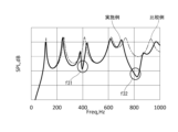
- Figures 3 to 5 show the frequency characteristics of the intake sound of one specific example. Note that Figures 3 to 5 show a comparison between the characteristics of a comparative example not having the partition wall 11 and the characteristics of the embodiment. These characteristics are those when a constant flow rate of air is flowed into the intake duct 1.
- Figure 3 shows the frequency characteristics of the intake sound measured at a position immediately before the center of the opening of the first flow path 12 in the intake port 3, that is, at point P1 in Figure 2. As shown in Figure 3, in front of the opening of the first flow path 12, the sound pressure level drops significantly at two frequencies, f11 and f12. These two frequencies correspond to the first and second order resonance frequencies in the second flow path 13.
- Figure 4 shows the frequency characteristics of the intake sound measured at a position immediately before the center of the opening of the second flow passage 13 in the intake port 3, that is, at point P2 in Figure 2. As shown in Figure 4, the sound pressure levels at two frequencies, f21 and f22, decrease in front of the opening of the second flow passage 13. These two frequencies correspond to the first and second order resonance frequencies in the first flow passage 12.
- Fig. 5 shows the frequency characteristics of the intake sound measured at a position immediately before the edge of the partition wall 11 at the intake port 3, that is, at point P3 in Fig. 2.
- the sound whose frequency characteristics are shown in Fig. 3 and the sound whose frequency characteristics are shown in Fig. 4 are combined, so that the sound pressure levels at two frequencies, f31 between f11 and f21, and f32 between f21 and f22, are reduced.
- the passage lengths L1, L2 and the passage cross-sectional area are tuned so that these silencing frequencies f31, f32 become the desired frequencies.
- the passage cross-sectional area of the second flow passage 13 along the outer periphery of the curved portion 4 is set to be slightly smaller than the passage cross-sectional area of the first flow passage 12 along the inner periphery, so the length of the partition wall 11 is set to obtain a desired silencing frequency, taking into consideration the difference between these passage cross-sectional areas.
- the intake noise generated according to the basic shape and dimensions of the intake device including the air cleaner case has several frequency peaks, but it is desirable to set the length of the partition wall 11 so that the resonator action of the intake duct 1 described above can be obtained to silencing relatively low frequency peaks.
- a Helmholtz resonator is attached to the duct to reduce intake noise of a specific frequency, but the lower the frequency of the Helmholtz resonator, the larger it becomes. Therefore, by utilizing the resonator action of the intake duct 1, a large Helmholtz resonator can be omitted.
- the intake duct 1 of the present invention can be used in combination with a Helmholtz resonator to reduce intake sound peaks other than the silencing frequency due to the air column resonance of the above-mentioned flow passages 12 and 13.
- the present invention is not limited to the above embodiment and various modifications are possible.
- the intake duct 1 in the above embodiment has been described as having an end connected to the air cleaner case, but it may also be configured such that another duct is interposed between the intake duct and the air cleaner case.
- the duct is not limited to a duct with a flat cross-sectional shape, and may have any cross-sectional shape.
Landscapes
- Engineering & Computer Science (AREA)
- Chemical & Material Sciences (AREA)
- Combustion & Propulsion (AREA)
- Mechanical Engineering (AREA)
- General Engineering & Computer Science (AREA)
- Exhaust Silencers (AREA)
Priority Applications (2)
| Application Number | Priority Date | Filing Date | Title |
|---|---|---|---|
| JP2025527328A JPWO2024261938A1 (https=) | 2023-06-22 | 2023-06-22 | |
| PCT/JP2023/023051 WO2024261938A1 (ja) | 2023-06-22 | 2023-06-22 | 内燃機関の吸気取り入れダクト |
Applications Claiming Priority (1)
| Application Number | Priority Date | Filing Date | Title |
|---|---|---|---|
| PCT/JP2023/023051 WO2024261938A1 (ja) | 2023-06-22 | 2023-06-22 | 内燃機関の吸気取り入れダクト |
Publications (1)
| Publication Number | Publication Date |
|---|---|
| WO2024261938A1 true WO2024261938A1 (ja) | 2024-12-26 |
Family
ID=93935209
Family Applications (1)
| Application Number | Title | Priority Date | Filing Date |
|---|---|---|---|
| PCT/JP2023/023051 Ceased WO2024261938A1 (ja) | 2023-06-22 | 2023-06-22 | 内燃機関の吸気取り入れダクト |
Country Status (2)
| Country | Link |
|---|---|
| JP (1) | JPWO2024261938A1 (https=) |
| WO (1) | WO2024261938A1 (https=) |
Citations (4)
| Publication number | Priority date | Publication date | Assignee | Title |
|---|---|---|---|---|
| JPH01174561U (https=) * | 1988-05-30 | 1989-12-12 | ||
| JPH11294279A (ja) * | 1998-04-08 | 1999-10-26 | Honda Motor Co Ltd | エンジンの吸気ダクト |
| JP2004150309A (ja) * | 2002-10-29 | 2004-05-27 | Toyo Roki Mfg Co Ltd | 吸気ダクト |
| JP2004230942A (ja) * | 2003-01-28 | 2004-08-19 | Inoac Corp | 車両用ダクト |
-
2023
- 2023-06-22 WO PCT/JP2023/023051 patent/WO2024261938A1/ja not_active Ceased
- 2023-06-22 JP JP2025527328A patent/JPWO2024261938A1/ja active Pending
Patent Citations (4)
| Publication number | Priority date | Publication date | Assignee | Title |
|---|---|---|---|---|
| JPH01174561U (https=) * | 1988-05-30 | 1989-12-12 | ||
| JPH11294279A (ja) * | 1998-04-08 | 1999-10-26 | Honda Motor Co Ltd | エンジンの吸気ダクト |
| JP2004150309A (ja) * | 2002-10-29 | 2004-05-27 | Toyo Roki Mfg Co Ltd | 吸気ダクト |
| JP2004230942A (ja) * | 2003-01-28 | 2004-08-19 | Inoac Corp | 車両用ダクト |
Also Published As
| Publication number | Publication date |
|---|---|
| JPWO2024261938A1 (https=) | 2024-12-26 |
Similar Documents
| Publication | Publication Date | Title |
|---|---|---|
| KR101598681B1 (ko) | 차량용 공명기 | |
| JP3818392B2 (ja) | 吸気システムまたは排気システムのための騒音減衰器 | |
| EP3438443B1 (en) | Noise reduction device for vehicle | |
| CN111512038B (zh) | 用于机动车发动机的宽带消声器 | |
| US5900595A (en) | Intake silencer device | |
| JP2000120497A (ja) | 自動車用吸気消音装置 | |
| CN107923349B (zh) | 车辆共振器 | |
| JPH1122571A (ja) | 内燃機関の吸気騒音低減装置 | |
| EP2495426A1 (en) | Swirl guiding acoustic device with an internal coaxially integrated swirl guide structure | |
| JP4968096B2 (ja) | 車両用内燃機関の吸気装置 | |
| KR102415846B1 (ko) | 차량용 공명기 | |
| KR20150095435A (ko) | 차량용 공명기 | |
| EP1908930A2 (en) | Exhaust silencer for automotive vehicles | |
| US11965442B2 (en) | Sound mitigation for a duct | |
| WO2024261938A1 (ja) | 内燃機関の吸気取り入れダクト | |
| CN111197546B (zh) | 整流结构件 | |
| JP6899278B2 (ja) | 消音装置 | |
| JP5859371B2 (ja) | 消音器付き吸気ダクト | |
| JP2008265717A (ja) | 空調用ダクト | |
| US10907590B2 (en) | Engine intake air duct | |
| US7992676B1 (en) | Compact tuned acoustic attenuation device | |
| US20250389243A1 (en) | Resonator for vehicle | |
| JP6823903B2 (ja) | 消音装置 | |
| KR101772267B1 (ko) | 차량용 공명기 | |
| JP6414447B2 (ja) | 吸気管構造 |
Legal Events
| Date | Code | Title | Description |
|---|---|---|---|
| 121 | Ep: the epo has been informed by wipo that ep was designated in this application |
Ref document number: 23941829 Country of ref document: EP Kind code of ref document: A1 |
|
| ENP | Entry into the national phase |
Ref document number: 2025527328 Country of ref document: JP Kind code of ref document: A |
|
| NENP | Non-entry into the national phase |
Ref country code: DE |