EP1908930A2 - Exhaust silencer for automotive vehicles - Google Patents
Exhaust silencer for automotive vehicles Download PDFInfo
- Publication number
- EP1908930A2 EP1908930A2 EP07380097A EP07380097A EP1908930A2 EP 1908930 A2 EP1908930 A2 EP 1908930A2 EP 07380097 A EP07380097 A EP 07380097A EP 07380097 A EP07380097 A EP 07380097A EP 1908930 A2 EP1908930 A2 EP 1908930A2
- Authority
- EP
- European Patent Office
- Prior art keywords
- chamber
- resonating
- outlet pipes
- casing
- gas
- Prior art date
- Legal status (The legal status is an assumption and is not a legal conclusion. Google has not performed a legal analysis and makes no representation as to the accuracy of the status listed.)
- Withdrawn
Links
Images

Classifications
-
- F—MECHANICAL ENGINEERING; LIGHTING; HEATING; WEAPONS; BLASTING
- F01—MACHINES OR ENGINES IN GENERAL; ENGINE PLANTS IN GENERAL; STEAM ENGINES
- F01N—GAS-FLOW SILENCERS OR EXHAUST APPARATUS FOR MACHINES OR ENGINES IN GENERAL; GAS-FLOW SILENCERS OR EXHAUST APPARATUS FOR INTERNAL-COMBUSTION ENGINES
- F01N1/00—Silencing apparatus characterised by method of silencing
- F01N1/02—Silencing apparatus characterised by method of silencing by using resonance
- F01N1/04—Silencing apparatus characterised by method of silencing by using resonance having sound-absorbing materials in resonance chambers
-
- F—MECHANICAL ENGINEERING; LIGHTING; HEATING; WEAPONS; BLASTING
- F01—MACHINES OR ENGINES IN GENERAL; ENGINE PLANTS IN GENERAL; STEAM ENGINES
- F01N—GAS-FLOW SILENCERS OR EXHAUST APPARATUS FOR MACHINES OR ENGINES IN GENERAL; GAS-FLOW SILENCERS OR EXHAUST APPARATUS FOR INTERNAL-COMBUSTION ENGINES
- F01N1/00—Silencing apparatus characterised by method of silencing
- F01N1/02—Silencing apparatus characterised by method of silencing by using resonance
- F01N1/023—Helmholtz resonators
-
- F—MECHANICAL ENGINEERING; LIGHTING; HEATING; WEAPONS; BLASTING
- F01—MACHINES OR ENGINES IN GENERAL; ENGINE PLANTS IN GENERAL; STEAM ENGINES
- F01N—GAS-FLOW SILENCERS OR EXHAUST APPARATUS FOR MACHINES OR ENGINES IN GENERAL; GAS-FLOW SILENCERS OR EXHAUST APPARATUS FOR INTERNAL-COMBUSTION ENGINES
- F01N1/00—Silencing apparatus characterised by method of silencing
- F01N1/08—Silencing apparatus characterised by method of silencing by reducing exhaust energy by throttling or whirling
- F01N1/082—Silencing apparatus characterised by method of silencing by reducing exhaust energy by throttling or whirling by passing the exhaust gases through porous members
-
- F—MECHANICAL ENGINEERING; LIGHTING; HEATING; WEAPONS; BLASTING
- F01—MACHINES OR ENGINES IN GENERAL; ENGINE PLANTS IN GENERAL; STEAM ENGINES
- F01N—GAS-FLOW SILENCERS OR EXHAUST APPARATUS FOR MACHINES OR ENGINES IN GENERAL; GAS-FLOW SILENCERS OR EXHAUST APPARATUS FOR INTERNAL-COMBUSTION ENGINES
- F01N2310/00—Selection of sound absorbing or insulating material
- F01N2310/04—Metallic wool, e.g. steel wool, copper wool or the like
-
- F—MECHANICAL ENGINEERING; LIGHTING; HEATING; WEAPONS; BLASTING
- F01—MACHINES OR ENGINES IN GENERAL; ENGINE PLANTS IN GENERAL; STEAM ENGINES
- F01N—GAS-FLOW SILENCERS OR EXHAUST APPARATUS FOR MACHINES OR ENGINES IN GENERAL; GAS-FLOW SILENCERS OR EXHAUST APPARATUS FOR INTERNAL-COMBUSTION ENGINES
- F01N2470/00—Structure or shape of exhaust gas passages, pipes or tubes
- F01N2470/02—Tubes being perforated
-
- F—MECHANICAL ENGINEERING; LIGHTING; HEATING; WEAPONS; BLASTING
- F01—MACHINES OR ENGINES IN GENERAL; ENGINE PLANTS IN GENERAL; STEAM ENGINES
- F01N—GAS-FLOW SILENCERS OR EXHAUST APPARATUS FOR MACHINES OR ENGINES IN GENERAL; GAS-FLOW SILENCERS OR EXHAUST APPARATUS FOR INTERNAL-COMBUSTION ENGINES
- F01N2470/00—Structure or shape of exhaust gas passages, pipes or tubes
- F01N2470/14—Plurality of outlet tubes, e.g. in parallel or with different length
Definitions
- the present invention relates to an exhaust silencer for automobile vehicles, particularly for sports automobiles.
- the object of the invention is to obtain a silencer with optimal acoustic performance in relation to its size or volume, as well as a reduction in the counter pressure to the flow of gases, i.e. while at the same time reducing the noise, it also minimizes the power it takes away from the engine of the vehicle.
- the invention can therefore be applied in the field of the manufacture of automobiles and their accessories.
- the most common silencers have an intake pipe leading to the chamber defined by the mentioned casing, through which pipe the gases generated by the engine of the vehicle enter the silencer, possibly one or more intermediate pipes, and finally a substantially cylindrical outlet pipe traversing the cover opposite to the cover traversed by the intake pipe, projecting therefrom.
- Internal separators divide said chamber and form the support for the intermediate pipes.
- the flow of gases in this type of silencers is guided, i.e. the gases pass through multi-resonators.
- This structure involves a drawback which is essentially focused on the fact that silencers are large if they are to be acoustically effective, which in turn means that they are heavy in relation to the power of engines. More specifically, this problem is because traditional silencers require a large volume of air to be able to dissipate the frequencies generated by the exhaust gases from the engine. Therefore, in order to obtain a certain acoustic performance a very large and therefore very heavy silencer is required.
- the exhaust silencer proposed by the invention resolves in a fully satisfactory manner the drawbacks described above, allowing to reduce its volume and therefore its weight, without detriment to its features from the acoustic silencer point of view, such that the performance in such aspect is optimized while at the same time the counter pressure generated by the flow of gases is reduced.
- the described silencer is structured from a casing similar to conventional casings, i.e. structured by means of a tubular frame closed by means of two end covers, but with the particularity that the gas intake occurs laterally through the middle area of the frame, said intake opening out into an expansion chamber the back wall of which is carried out in a multi-resonating membrane on which the gases collide, which membrane rests through a steel wool layer on an absorbent material filler taking up this area of the casing. It can be defined as a multiple resonator opposite to the flow of gases.
- the mentioned expansion chamber extends, bent and orthogonally, into a pair of outlet pipes which lead towards the closest end cover of the casing, also surrounded by an absorbent material, and a high frequency multi-resonator is arranged in each one.
- This assembly forms a Helmholtz resonator and ends up filtering the dominant frequencies of the exhaust noise causing the greatest auditory discomfort.
- the intake pipe (3) accesses the casing of the silencer through the middle area of the tubular frame (1), as can also be seen in Figure 1, whereas the outlets (5) for said gases are located inside the casing next to one of its covers (2), which outlets are connected to the actual exhaust pipes (4).
- outlets (5) internally incorporate high frequency multi-resonators (6).
- the frequencies of the gases are filtered with a guided flow in these pipes (5) by means of the mentioned multi-resonators (6).
- said pipe opens out into an expansion chamber (7), which is directly communicated with the outlet pipes (5) and delimited by a multi-resonating membrane (8) on which the gases collide, causing the filtering of high and middle frequencies.
- This frequency filtering is combined with the presence of a absorbent material (9) for absorbing sound pressure surrounding both the expansion chamber (7) and the outlet pipes (5), a layer of steel wool (10) being located between this absorbent material (9) and the multi-resonating membrane (8), which wool prevents the depression of the gases, generated by the engine on some occasions, from suctioning the absorbent material (9).
- a Helmholtz resonator neck (11) projects from the expansion chamber (7), opposite to the outlet pipes (5), which opens out into an anti-resonating chamber (12) taking up a good part of the casing (1), specifically in its area opposite to the outlet pipes (5).
- the assembly formed by the resonator neck (11) and the anti-resonating chamber (12) prevents the gas from resonating at frequencies causing noise that bothers the ears.
- the energy provided by said frequency is dissipated in the form of heat, compressing the gases in the chamber (12) by means of a gas column generated by the resonator neck (11).
- Tuning in on the most outstanding frequencies is obtained by means of the specific sizing of the neck-chamber (11-12) assembly, this sizing changing according to a very small margin of frequencies because it is calculated for a certain frequency at certain revolutions.
Landscapes
- Engineering & Computer Science (AREA)
- Chemical & Material Sciences (AREA)
- Combustion & Propulsion (AREA)
- Mechanical Engineering (AREA)
- General Engineering & Computer Science (AREA)
- Exhaust Silencers (AREA)
Abstract
Description
- The present invention relates to an exhaust silencer for automobile vehicles, particularly for sports automobiles.
- The object of the invention is to obtain a silencer with optimal acoustic performance in relation to its size or volume, as well as a reduction in the counter pressure to the flow of gases, i.e. while at the same time reducing the noise, it also minimizes the power it takes away from the engine of the vehicle.
- The invention can therefore be applied in the field of the manufacture of automobiles and their accessories.
- As is well known, current silencers intended for being intercalated in a vehicle exhaust system are structured, among other technologies, by means of a casing based on a tubular frame with two end covers. Said casing houses more or less complicated designs of resonators, an expansion chamber, Helmholtz resonators, etc, in addition to a material that can absorb high frequency noise, generally fiberglass.
- The most common silencers have an intake pipe leading to the chamber defined by the mentioned casing, through which pipe the gases generated by the engine of the vehicle enter the silencer, possibly one or more intermediate pipes, and finally a substantially cylindrical outlet pipe traversing the cover opposite to the cover traversed by the intake pipe, projecting therefrom. Internal separators divide said chamber and form the support for the intermediate pipes. The flow of gases in this type of silencers is guided, i.e. the gases pass through multi-resonators.
- This structure involves a drawback which is essentially focused on the fact that silencers are large if they are to be acoustically effective, which in turn means that they are heavy in relation to the power of engines. More specifically, this problem is because traditional silencers require a large volume of air to be able to dissipate the frequencies generated by the exhaust gases from the engine. Therefore, in order to obtain a certain acoustic performance a very large and therefore very heavy silencer is required.
- Furthermore, the dimensions required for silencers are also determined by the need to maintain certain counter pressure levels.
- The exhaust silencer proposed by the invention resolves in a fully satisfactory manner the drawbacks described above, allowing to reduce its volume and therefore its weight, without detriment to its features from the acoustic silencer point of view, such that the performance in such aspect is optimized while at the same time the counter pressure generated by the flow of gases is reduced.
- To that end and more specifically, the described silencer is structured from a casing similar to conventional casings, i.e. structured by means of a tubular frame closed by means of two end covers, but with the particularity that the gas intake occurs laterally through the middle area of the frame, said intake opening out into an expansion chamber the back wall of which is carried out in a multi-resonating membrane on which the gases collide, which membrane rests through a steel wool layer on an absorbent material filler taking up this area of the casing. It can be defined as a multiple resonator opposite to the flow of gases.
- The mentioned expansion chamber extends, bent and orthogonally, into a pair of outlet pipes which lead towards the closest end cover of the casing, also surrounded by an absorbent material, and a high frequency multi-resonator is arranged in each one.
- Located opposite to these outlet pipes there is a pipe connecting the expansion chamber with a resonating chamber, taking up a little less than half the casing opposite to the outlet pipes.
- This assembly forms a Helmholtz resonator and ends up filtering the dominant frequencies of the exhaust noise causing the greatest auditory discomfort.
- To complement the description being made and for the purpose of aiding to better understand the features of the invention according to a practical embodiment thereof, a set of drawings is attached as an integral part of said description which show the following with an illustrative and non-limiting character:
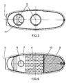
- Figure 1 shows a schematic perspective view of an exhaust silencer for automotive vehicles carried out according to the object of the present invention.
- Figure 2 shows a plan view of the same silencer.
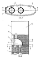
- Figure 3 shows an elevational view from its end corresponding to the outlet pipes.
- Figure 4 shows a cross section view of a detail of the silencer as a whole according to section line A-A of Figure (3).
- Figure 5 shows a section view of a detail of the silencer according to section line B-B of Figure 4.
- Figure 6 finally shows another section view of a detail along a plane parallel to that of the previous figure according to section line C-C of Figure 4.
- In view of the discussed figures and especially Figure 1, it can be seen how in the described silencer there is a casing based on a tubular frame (1) and two end covers (2) closing it, said casing forming a gas tight chamber in which there is arranged an intake pipe (3) and a pair of outlet pipes (4).
- The intake pipe (3) accesses the casing of the silencer through the middle area of the tubular frame (1), as can also be seen in Figure 1, whereas the outlets (5) for said gases are located inside the casing next to one of its covers (2), which outlets are connected to the actual exhaust pipes (4).
- These outlets (5) internally incorporate high frequency multi-resonators (6). The frequencies of the gases are filtered with a guided flow in these pipes (5) by means of the mentioned multi-resonators (6).
- In reference again to the gas intake pipe (3), said pipe opens out into an expansion chamber (7), which is directly communicated with the outlet pipes (5) and delimited by a multi-resonating membrane (8) on which the gases collide, causing the filtering of high and middle frequencies. This frequency filtering is combined with the presence of a absorbent material (9) for absorbing sound pressure surrounding both the expansion chamber (7) and the outlet pipes (5), a layer of steel wool (10) being located between this absorbent material (9) and the multi-resonating membrane (8), which wool prevents the depression of the gases, generated by the engine on some occasions, from suctioning the absorbent material (9).
- A Helmholtz resonator neck (11) projects from the expansion chamber (7), opposite to the outlet pipes (5), which opens out into an anti-resonating chamber (12) taking up a good part of the casing (1), specifically in its area opposite to the outlet pipes (5). The assembly formed by the resonator neck (11) and the anti-resonating chamber (12) prevents the gas from resonating at frequencies causing noise that bothers the ears.
- As previously stated, once the outstanding frequency has been detected, the energy provided by said frequency is dissipated in the form of heat, compressing the gases in the chamber (12) by means of a gas column generated by the resonator neck (11). Tuning in on the most outstanding frequencies is obtained by means of the specific sizing of the neck-chamber (11-12) assembly, this sizing changing according to a very small margin of frequencies because it is calculated for a certain frequency at certain revolutions.
Claims (3)
- An exhaust silencer for automobile vehicles, of the type incorporating a casing determining a gas tight chamber, based on a tubular frame and two end covers, and of those having a gas intake pipe and at least one outlet pipe for such gases, characterized in that the gas intake is located in the middle area of the tubular frame, said intake opening out into an expansion chamber, on the back wall of which the gases collide, which back wall being carried out in a multi-resonating membrane outside of which the chamber formed by the casing is filled in this area with an absorbent material, two outlet pipes being arranged on one side of the mentioned intake, perpendicular thereto and connected therewith through the mentioned expansion chamber, which outlet pipes internally house respective high frequency multi-resonators, whereas a Helmholtz resonator neck is arranged opposite to said outlets which opens out into an anti-resonating chamber located opposite to the gas outlets.
- An exhaust silencer for automotive vehicles according to claim 1, characterized in that arranged between the multi-resonating membrane and the absorbent material there is a layer of steel wool stabilizing said absorbent material, also having provided that this absorbent material also surrounds both the outlet pipes and the resonator neck.
- An exhaust silencer for automotive vehicles according to the previous claims, characterized in that the empty anti-resonating chamber affects a little less than half the casing opposite to the outlet pipes, said anti-resonating chamber together with the resonator neck defining a dampener for the frequencies causing noise that bothers the ears, while at the same time the multi-resonating membrane filters high and middle frequencies as the gases collide on it.
Applications Claiming Priority (1)
| Application Number | Priority Date | Filing Date | Title |
|---|---|---|---|
| ES200602160U ES1063818Y (en) | 2006-10-03 | 2006-10-03 | EXHAUST SILENCE FOR AUTOMOBILE VEHICLES |
Publications (2)
| Publication Number | Publication Date |
|---|---|
| EP1908930A2 true EP1908930A2 (en) | 2008-04-09 |
| EP1908930A3 EP1908930A3 (en) | 2009-09-02 |
Family
ID=37810274
Family Applications (1)
| Application Number | Title | Priority Date | Filing Date |
|---|---|---|---|
| EP07380097A Withdrawn EP1908930A3 (en) | 2006-10-03 | 2007-04-11 | Exhaust silencer for automotive vehicles |
Country Status (2)
| Country | Link |
|---|---|
| EP (1) | EP1908930A3 (en) |
| ES (1) | ES1063818Y (en) |
Cited By (6)
| Publication number | Priority date | Publication date | Assignee | Title |
|---|---|---|---|---|
| WO2017144266A1 (en) | 2016-02-26 | 2017-08-31 | Tenneco Gmbh | Exhaust muffler element and exhaust muffler |
| DE102016103466A1 (en) | 2016-02-26 | 2017-08-31 | Tenneco Gmbh | Exhaust silencer element |
| DE102016103459A1 (en) | 2016-02-26 | 2017-08-31 | Tenneco Gmbh | exhaust silencer |
| DE102016103453A1 (en) | 2016-02-26 | 2017-08-31 | Tenneco Gmbh | exhaust system |
| CN110307059A (en) * | 2018-03-20 | 2019-10-08 | 佛吉亚排放控制技术美国有限公司 | The method in the acoustic voiume portion of the No leakage for vehicle frame member is provided |
| US20210355850A1 (en) * | 2020-05-13 | 2021-11-18 | Hyundai Motor Company | Exhaust system noise reduction device of vehicle |
Families Citing this family (1)
| Publication number | Priority date | Publication date | Assignee | Title |
|---|---|---|---|---|
| CN109184969B (en) * | 2018-10-31 | 2024-06-04 | 马勒汽车技术(中国)有限公司 | Air filtering device of vehicle and air intake system of vehicle |
Family Cites Families (2)
| Publication number | Priority date | Publication date | Assignee | Title |
|---|---|---|---|---|
| US6892853B2 (en) * | 2003-05-01 | 2005-05-17 | Agency For Science Technology And Research | High performance muffler |
| SE528092C2 (en) * | 2004-06-17 | 2006-09-05 | Ggp Sweden Ab | Combustion engine device |
-
2006
- 2006-10-03 ES ES200602160U patent/ES1063818Y/en not_active Expired - Fee Related
-
2007
- 2007-04-11 EP EP07380097A patent/EP1908930A3/en not_active Withdrawn
Non-Patent Citations (1)
| Title |
|---|
| None |
Cited By (10)
| Publication number | Priority date | Publication date | Assignee | Title |
|---|---|---|---|---|
| WO2017144266A1 (en) | 2016-02-26 | 2017-08-31 | Tenneco Gmbh | Exhaust muffler element and exhaust muffler |
| DE102016103466A1 (en) | 2016-02-26 | 2017-08-31 | Tenneco Gmbh | Exhaust silencer element |
| DE102016103459A1 (en) | 2016-02-26 | 2017-08-31 | Tenneco Gmbh | exhaust silencer |
| DE102016103453A1 (en) | 2016-02-26 | 2017-08-31 | Tenneco Gmbh | exhaust system |
| DE102016103453B4 (en) | 2016-02-26 | 2023-06-15 | Tenneco Gmbh | Exhaust silencer, catalytic converter and exhaust system |
| DE102016103459B4 (en) | 2016-02-26 | 2023-09-21 | Tenneco Gmbh | Exhaust silencer |
| DE102016103466B4 (en) | 2016-02-26 | 2024-12-12 | Tenneco Gmbh | exhaust silencer element and exhaust silencer |
| CN110307059A (en) * | 2018-03-20 | 2019-10-08 | 佛吉亚排放控制技术美国有限公司 | The method in the acoustic voiume portion of the No leakage for vehicle frame member is provided |
| US20210355850A1 (en) * | 2020-05-13 | 2021-11-18 | Hyundai Motor Company | Exhaust system noise reduction device of vehicle |
| US11846216B2 (en) * | 2020-05-13 | 2023-12-19 | Hyundai Motor Company | Exhaust system noise reduction device of vehicle |
Also Published As
| Publication number | Publication date |
|---|---|
| ES1063818U (en) | 2006-12-01 |
| EP1908930A3 (en) | 2009-09-02 |
| ES1063818Y (en) | 2007-03-01 |
Similar Documents
| Publication | Publication Date | Title |
|---|---|---|
| US7942239B2 (en) | Exhaust muffler | |
| EP1908930A2 (en) | Exhaust silencer for automotive vehicles | |
| CN103270260B (en) | Silencer for vehicles | |
| CN110388245B (en) | Muffler comprising a Helmholtz resonator and vehicle comprising such a muffler | |
| US6595319B1 (en) | Muffler | |
| US6681889B2 (en) | Exhaust muffler for a fuel-operated heating device | |
| US8136627B2 (en) | Exhaust silencer device for internal combustion engine | |
| CN205654400U (en) | Silencer | |
| JP4573463B2 (en) | Muffler for internal combustion engine | |
| JP2011027038A (en) | Muffler | |
| JPS6328201B2 (en) | ||
| JP2006207378A (en) | Noise reduction device for exhaust system and exhaust system having the same | |
| JP2009197590A (en) | Silencer and manufacturing method of silencer | |
| JP6169035B2 (en) | Silencer structure for exhaust noise of fuel cell vehicles | |
| KR200457936Y1 (en) | Automotive Silencer | |
| US10161275B2 (en) | Compact muffler having multiple reactive cavities providing multi-spectrum attenuation for enhanced noise suppression | |
| KR102375148B1 (en) | Muffler for vehicles | |
| JP2013029046A (en) | Vehicle muffler | |
| JPS59226222A (en) | Exhaust noise reducing apparatus for automotive engine | |
| CN113623090A (en) | Air inlet pipeline and motor vehicle | |
| JP2010185427A (en) | Muffler | |
| CN216043947U (en) | Muffler for vehicle exhaust system | |
| CN105339623A (en) | Exhaust muffler | |
| JP3344239B2 (en) | Automotive exhaust silencer | |
| CN222910145U (en) | High-order intake duct, air intake system and vehicle |
Legal Events
| Date | Code | Title | Description |
|---|---|---|---|
| PUAI | Public reference made under article 153(3) epc to a published international application that has entered the european phase |
Free format text: ORIGINAL CODE: 0009012 |
|
| 17P | Request for examination filed |
Effective date: 20070412 |
|
| AK | Designated contracting states |
Kind code of ref document: A2 Designated state(s): AT BE BG CH CY CZ DE DK EE ES FI FR GB GR HU IE IS IT LI LT LU LV MC MT NL PL PT RO SE SI SK TR |
|
| AX | Request for extension of the european patent |
Extension state: AL BA HR MK RS |
|
| PUAL | Search report despatched |
Free format text: ORIGINAL CODE: 0009013 |
|
| AK | Designated contracting states |
Kind code of ref document: A3 Designated state(s): AT BE BG CH CY CZ DE DK EE ES FI FR GB GR HU IE IS IT LI LT LU LV MC MT NL PL PT RO SE SI SK TR |
|
| AX | Request for extension of the european patent |
Extension state: AL BA HR MK RS |
|
| 17Q | First examination report despatched |
Effective date: 20100222 |
|
| AKX | Designation fees paid |
Designated state(s): DE ES FR GB IT |
|
| GRAP | Despatch of communication of intention to grant a patent |
Free format text: ORIGINAL CODE: EPIDOSNIGR1 |
|
| GRAC | Information related to communication of intention to grant a patent modified |
Free format text: ORIGINAL CODE: EPIDOSCIGR1 |
|
| GRAJ | Information related to disapproval of communication of intention to grant by the applicant or resumption of examination proceedings by the epo deleted |
Free format text: ORIGINAL CODE: EPIDOSDIGR1 |
|
| STAA | Information on the status of an ep patent application or granted ep patent |
Free format text: STATUS: THE APPLICATION IS DEEMED TO BE WITHDRAWN |
|
| 18D | Application deemed to be withdrawn |
Effective date: 20111101 |