WO2024261851A1 - 光給電システム及び光給電方法 - Google Patents
光給電システム及び光給電方法 Download PDFInfo
- Publication number
- WO2024261851A1 WO2024261851A1 PCT/JP2023/022742 JP2023022742W WO2024261851A1 WO 2024261851 A1 WO2024261851 A1 WO 2024261851A1 JP 2023022742 W JP2023022742 W JP 2023022742W WO 2024261851 A1 WO2024261851 A1 WO 2024261851A1
- Authority
- WO
- WIPO (PCT)
- Prior art keywords
- optical
- power supply
- light source
- splitter
- optical power
- Prior art date
- Legal status (The legal status is an assumption and is not a legal conclusion. Google has not performed a legal analysis and makes no representation as to the accuracy of the status listed.)
- Ceased
Links
Images





Classifications
-
- H—ELECTRICITY
- H02—GENERATION; CONVERSION OR DISTRIBUTION OF ELECTRIC POWER
- H02J—ELECTRIC POWER NETWORKS; CIRCUIT ARRANGEMENTS OR SYSTEMS FOR SUPPLYING OR DISTRIBUTING ELECTRIC POWER; SYSTEMS FOR STORING ELECTRIC ENERGY
- H02J50/00—Circuit arrangements or systems for wireless supply or distribution of electric power
- H02J50/30—Circuit arrangements or systems for wireless supply or distribution of electric power using light, e.g. lasers
Definitions
- the present invention relates to an optical power supply system and an optical power supply method.
- FIG. 9 is a diagram showing an example of the configuration of an optical power supply system using a conventional optical power supply method.
- an optical signal is transmitted from a light source provided in a station building or the like to an optical power supply unit installed in a power supply target area, which is, for example, a non-electrified area, via an optical power supply line using optical fiber.
- the network configuration of the optical power supply line is a SS (Single Star) configuration that does not perform branching in order to reduce branching loss.
- the optical signal transmitted via the optical power supply line is received by the PD (Photodiode) of the optical power supply unit.
- the received optical signal is converted into an electrical signal by the PD and supplied as power to the equipment in the power supply target area.
- optical fiber which is an optical power supply line
- optical power supply unit must be newly laid over the long distance from the light source installed in a station or the like to the optical power supply unit. Therefore, with conventional optical power supply methods, it is necessary to take time and effort to lay optical fiber over such a long distance.
- a method can be considered in which unused optical signals in existing PON networks used for data communications are transmitted to the optical power supply unit and used to supply power to the target area, without laying new optical fiber.
- the network paths are branched and merged by an optical splitter.
- a bidirectional optical coupler with multiple inputs and multiple outputs is used as the optical splitter.
- the optical coupler has multiple terminals on both the central office side and the user's premises side, for example.
- the optical signal In an optical communication system using a PON, the optical signal generally flows to all of these terminals, so the optical signal is wasted and not used in the unused terminals that are terminated.
- the present invention was made in consideration of the above technical background, and aims to provide a technology that can supply power through optical power supply while suppressing increases in costs.
- One aspect of the present invention is an optical power supply unit that supplies power obtained from a received optical signal to a power supply target device, a multi-input, multi-output bidirectional optical splitter that transmits a first optical signal sent from a first light source to a second light source side and the optical power supply unit, and transmits a second optical signal sent from a second light source to the first light source side and the optical power supply unit, and an optical fiber that connects two terminals on one side of the optical splitter to transmit the optical signal output from the optical splitter in the upstream and downstream directions.
- the optical power supply unit combines power obtained from the first optical signal sent from the first light source and transmitted through the optical splitter with power obtained from the second optical signal sent from the second light source, output to the return unit through the optical splitter, and transmitted again through the optical splitter after being directionally converted, and outputs the combined power to the device to be powered.
- An aspect of the present invention is an optical power supply method including the steps of: causing an optical splitter to transmit a first optical signal sent from a first light source to a second light source side and an optical power supply unit; causing the optical splitter to transmit a second optical signal sent from a second light source to the first light source side and the optical power supply unit; converting the upstream and downstream directions of the optical signal output from the optical splitter using an optical fiber connecting two terminals on one side of the optical splitter, re-inputting the optical signal into the optical splitter and folding it back; and combining the power obtained from the first optical signal sent from the first light source and transmitted through the optical splitter and the power obtained from the second optical signal sent from the second light source, output to the folding unit via the optical splitter, and transmitted again through the optical splitter after being directionally converted, and outputting the combined power to a device to be powered.
- FIG. 1 is a diagram illustrating an example of the configuration of a conventional optical communication system using a PON.
- FIG. 1 is a diagram illustrating an example of the configuration of a conventional optical power supply system 1c.
- FIG. 1 is a diagram illustrating an example of the configuration of a conventional optical power supply system 1d.
- 1 is an overall configuration diagram of an optical power supply system 1 according to an embodiment of the present invention.
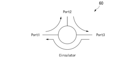
- FIG. 2 is a diagram showing an example of the configuration of an optical circulator 60 according to an embodiment of the present invention.
- 4 is a flowchart showing an operation of the optical power supply system 1 according to the embodiment of the present invention.
- FIG. 1 is a diagram illustrating an example of the configuration of a conventional optical communication system using a PON.
- FIG. 1 is a diagram illustrating an example of the configuration of a conventional optical power supply system 1c.
- FIG. 1 is a diagram illustrating an example of the configuration of a conventional optical power supply system 1d.
- 1 is an overall configuration diagram
- FIG. 11 is a diagram illustrating a configuration of a return of a network path in an optical power supply system 1a according to a first modified example of an embodiment of the present invention.
- FIG. 11 is a diagram illustrating a configuration of a return of a network path in an optical power supply system 1b according to a second modified example of the embodiment of the present invention.
- FIG. 1 is a diagram showing an example of a configuration of an optical power supply system using a conventional optical power supply method.
- optical power supply system and the optical power supply method of the embodiment will be described with reference to the drawings.
- a configuration example of a conventional general PON system and two configuration examples of a conventional optical power supply system for comparison will be described first.
- FIG. 1 is a diagram showing the configuration of a conventional PON system.
- the conventional PON system includes a light source 12 and an optical splitter 30.
- the PON system also includes a plurality of ONUs (not shown) installed in each user's premises, and optical fibers connecting the light source 12, the optical splitter 30, and the ONUs in each user's premises.
- the light source 12 is installed in a building such as a station building.
- the light source 12 is a light source for transmitting optical signals carrying communication data from the station building to the ONUs in multiple user homes.
- a PON configuration is used as the network configuration between the light source 12 and the ONUs in each user home.
- the optical signal sent from the light source 12 is split by an optical splitter 30 installed on the network path, and is received by the ONUs in each user home.
- the optical splitter 30 is a multi-input, multi-output optical coupler with multiple terminals on both the station side and the user premises side.
- the optical splitter 30 illustrated in FIG. 1 is a 4-to-4 bidirectional input/output optical coupler with four terminals on the station side and four terminals on the user premises side.
- optical signals in different wavelength regions are used for the upstream and downstream signals.
- the PON system shown in FIG. 1 is configured to use optical signals in the wavelength region of 1260 to 1360 nm for the upstream signal and optical signals in the wavelength region of 1480 to 1580 nm for the downstream signal.
- one of the four terminals on the station side of the optical splitter 30 is connected to the light source 12 in the station, while the remaining three terminals are unused terminals.
- the unused terminals referred to here are unused terminals of the optical splitter 30 that are not connected to either the light source 12 or the ONU in the user's premises. Therefore, when considering obtaining power from the transmitted optical signal by optical power supply, the power that could be obtained from the optical signal output from the three unused terminals on the station side of the optical splitter 30 is wasted without being utilized.
- FIG. 2 is a diagram showing an example of the configuration of a conventional optical power supply system 1c.
- the conventional optical power supply system 1c shown in Figure 2 is an optical power supply system that utilizes the conventional PON system described above.
- the optical power supply system 1c further includes an optical power supply unit 2.
- the optical power supply system 1c includes a light source 12, an optical splitter 30, and an optical power supply unit 2.
- the optical power supply system 1c also includes a plurality of ONUs (not shown) installed in each user's home, and optical fibers connecting the light source 12, the optical splitter 30, and the ONUs in each user's home.
- the optical power supply unit 2 generates power using optical signals transmitted from the optical splitter 30 of the PON, and supplies power to the target devices within the target power supply area.
- the target devices are devices that require a large amount of power, such as ONUs (optical network units).
- the optical power supply unit 2 has two PDs (photodiodes) 20 (PD20-1 and PD20-2).
- the number of PDs 20 is not limited to two, and may be the same as the number of unused terminals on the user's premises side of the optical splitter 30.
- the PDs 20, the optical splitter 30, and the optical power supply unit 2 are connected by optical power supply lines 52.
- the optical power supply lines 52 may be, for example, optical fibers.
- the light source 12 is installed in a building such as a station building.
- the light source 12 is a light source for transmitting optical signals carrying communication data from the station building to the ONUs in multiple user homes.
- a PON configuration is used as the network configuration between the light source 12 and the ONUs in each user home.
- the optical signal sent from the light source 12 is split by an optical splitter 30 installed on the network path, and is received by the ONUs in each user home.
- the optical splitter 30 is installed, for example, on a utility pole.
- the optical splitter 30 splits the optical signal (downstream signal) sent from the light source 12 in the direction of multiple user homes.
- the optical splitter 30 also merges the optical signals (upstream signals) sent from the ONUs in each user home in the direction of the station.
- the optical splitter 30 is a multi-input, multi-output optical coupler with multiple terminals on both the station side and the user premises side.
- the optical splitter 30 illustrated in FIG. 2 is a 4-to-4 input/output optical coupler with four terminals on both the station side and the user premises side.
- optical signals in different wavelength regions are used for the upstream signal and the downstream signal.
- an optical signal in the wavelength region of 1260 to 1360 [nm] is used for the upstream signal
- an optical signal in the wavelength region of 1480 to 1580 [nm] is used for the downstream signal.
- one of the four terminals on the station side of the optical splitter 30 is connected to the station light source 12, while the remaining three terminals are unused terminals.
- Figure 2 shows two user homes as an example.
- two of the four terminals on the user home side of the optical splitter 30 are connected to an ONU (not shown) in each user home, and the remaining two terminals are connected to PD20-1 and PD20-2, respectively. Therefore, the optical signal sent out by the light source 12 is also received by PD20-1 and PD20-2, respectively.
- PD20-1 and PD20-2 each obtain power by converting the received optical signal into an electrical signal.
- PD20-1 and PD20-2 each supply the obtained power to the target devices in the target power supply area.
- PD20-1 and PD20-2 obtain power by receiving optical signals carrying communication data transmitted from the PON station to users' homes.
- PD20-1 and PD20-2 are connected in series. As shown in FIG. 2, the power obtained by PD20-1 is output to PD20-2. The power output from PD20-1 and the power obtained by PD20-2 are combined and output to the power supply target device in the power supply target area.
- PD20-1 and PD20-2 are connected in series is not limited to this, and may be the opposite of the order shown in FIG. 2, for example.
- PD20-1 and PD20-2 may be connected in parallel.
- the current can be increased more than when they are connected in series.
- the voltage can be increased more than when they are connected in parallel.
- the conventional optical power supply system 1c supplies optical power to the target devices in the target area via a network path that goes through an optical power supply line 52 connected to one or more unused terminals on the user's premises side of the optical splitter 30, out of multiple network paths in a PON configuration that transmits optical signals sent from the light source 12.
- the conventional optical power supply system 1c described above is configured to utilize the unused terminals on the user premises side of the optical splitter 30 for optical power supply, but the unused terminals on the central office side are left unused. Therefore, in the optical power supply system 1c, when considering obtaining power from the optical signals sent from the ONUs in each user premises, the power that could be obtained from the optical signals output from the three unused terminals on the central office side of the optical splitter 30 is wasted and not used.
- the conventional optical power supply system 1d described below is configured to obtain power not only from optical signals transmitted through one or more unused terminals on the user premises side of the PON optical splitter 30, but also from optical signals transmitted through one or more unused terminals on the central office side of the optical splitter 30.
- FIG. 3 is a diagram showing an example of the configuration of a conventional optical power supply system 1d.
- the optical power supply system 1d includes a light source 12, an optical splitter 30, and an optical power supply unit 2b.
- the optical power supply system 1d also includes a plurality of ONUs (not shown) installed in each user's home, and optical fibers connecting the light source 12, the optical splitter, and each ONU.
- the optical power supply unit 2b generates power using an optical signal transmitted from the optical splitter 30 of the PON, and supplies power to the target devices in the target power supply area.
- the optical power supply unit 2b has five PDs 20 (PD20-1 to PD20-5).
- the number of PDs 20 is not limited to five, and may be the same as the number of unused terminals on the user premises side and the central office side of the optical splitter 30, for example.
- Each PD 20, the optical splitter 30, and the sensor 40 are connected by an optical power supply line 52.
- an optical fiber is used for the optical power supply line 52.
- the light source 12 is installed in a building such as a station building.
- the light source 12 is a light source for transmitting optical signals carrying communication data from the station building to the ONUs in multiple user homes.
- a PON configuration is used as the network configuration between the light source 12 and the ONUs in each user home.
- the optical signal sent from the light source 12 is split by an optical splitter 30 installed on the network path, and is received by the ONUs in each user home.
- the optical splitter 30 is installed, for example, on a utility pole.
- the optical splitter 30 splits the optical signal (downstream signal) sent from the light source 12 in the direction of multiple user homes.
- the optical splitter 30 also merges the optical signals (upstream signals) sent from the ONUs in each user home in the direction of the station.
- the optical splitter 30 is a multi-input, multi-output optical coupler with multiple terminals on both the station side and the user premises side.
- the optical splitter 30 illustrated in FIG. 3 is a 4-to-4 input/output optical coupler with four terminals on both the station side and the user premises side.
- the upstream signal and the downstream signal use optical signals in different wavelength regions.
- an optical signal in the wavelength region of 1260 to 1360 [nm] is used for the upstream signal
- an optical signal in the wavelength region of 1480 to 1580 [nm] is used for the downstream signal.
- FIG. 3 also illustrates two user homes as an example. Therefore, the optical signal sent by the ONU in the user home is also received by PD20-1 to PD20-3, respectively. Each of PD20-1 to PD20-3 obtains power by converting the received optical signal into an electrical signal.
- the optical power supply system 1d illustrated in FIG. 3 of the four terminals on the user premises side of the optical splitter 30, two terminals are connected to an ONU (not shown) in the user premises, and the remaining two terminals are connected to PD20-4 and PD20-5, respectively. Therefore, the optical signal sent out by the light source 12 is also received by PD20-4 and PD20-5, respectively. Each of PD20-4 and PD20-5 obtains power by converting the received optical signal into an electrical signal.
- PD20-1 to PD20-3 obtain power by receiving optical signals carrying communication data transmitted from the ONU in the user's premises to the PON station.
- PD20-4 and PD20-5 obtain power by receiving optical signals carrying communication data transmitted from the PON station to the user's premises.
- PD20-1 to PD20-5 are connected in series. As shown in Figure 3, the power obtained from PD20-1 to PD20-5 in order is added together and output to the target device in the target power supply area.
- PD20-1 to PD20-5 are connected in series is not limited to this, and may be the opposite of the order shown in FIG. 3, for example. Note that some or all of PD20-1 to PD20-5 may be connected in parallel. When PD20-1 to PD20-5 are connected in parallel, the current can be increased more than when they are connected in series. On the other hand, when PD20-1 to PD20-5 are connected in series, the voltage can be increased more than when they are connected in parallel.
- the optical power supply system 1d can supply more power to the power supply target devices in the power supply target area compared to the optical power supply system 1c described above.
- optical power supply system 1 in the case of the conventional optical power supply systems 1c and 1d described above, in order to ensure sufficient power, it is necessary to transmit optical signals output from as many unused terminals of the optical splitter 30 as possible to the optical power supply units 2 and 2b, respectively. Therefore, in configurations such as the conventional optical power supply systems 1c and 1d, it is necessary to lay optical fibers, which are the optical power supply lines 52, between the many unused terminals and the optical power supply unit 2 (or the optical power supply unit 2b), which increases installation costs, which is a problem.
- the optical power supply system 1 in the embodiment described below reduces the number of optical fibers to be laid, making it possible to supply power through optical power supply while suppressing increases in costs.
- FIG. 4 is a diagram showing the overall configuration of the optical power supply system 1 in the embodiment of the present invention.
- the optical power supply system 1 in the embodiment is an optical power supply system that utilizes the conventional PON system described above.
- the optical power supply system 1 includes a light source 12, an optical splitter 30, an optical circulator 60, and an optical power supply unit 2.
- the optical power supply system 1 also includes a plurality of ONUs (not shown) installed in each user's premises, and optical fibers connecting the light source 12, the optical splitter 30, and the ONUs in each user's premises.
- the optical power supply unit 2 generates power using optical signals transmitted from the PON, and supplies power to devices within the power supply area. As shown in FIG. 4, the optical power supply unit 2 has two PDs 20 (PD20-1 and PD20-2). The number of PDs 20 is not limited to two, and may be the same as the number of unused terminals on the user premises side of the optical splitter 30.
- the PDs 20, the optical splitter 30, and the optical circulator 60 are connected by an optical power supply line 52. For example, optical fiber is used for the optical power supply line 52.
- the optical power supply unit 2 As shown in FIG. 4, in the optical power supply system 1 of the embodiment, all unused terminals on the station side of the optical splitter 30 are connected to the optical circulator 60. Therefore, in this embodiment, it is not necessary for the optical power supply unit 2 to be provided with PDs 20 for the unused terminals on the user premises side of the optical splitter 30.
- the light source 12 is installed in a building such as a station building.
- the light source 12 is a light source for transmitting optical signals carrying communication data from the station building to the ONUs in multiple user homes.
- a PON configuration is used as the network configuration between the light source 12 and the ONUs in each user home.
- the optical signal sent from the light source 12 is split by an optical splitter 30 installed on the network path, and is received by the ONUs in each user home.
- the optical splitter 30 is installed, for example, on a utility pole.
- the optical splitter 30 splits the optical signal (downstream signal) sent from the light source 12 in the direction of multiple user homes.
- the optical splitter 30 also merges the optical signals (upstream signals) sent from the ONUs in each user home in the direction of the station.
- the optical splitter 30 in this embodiment is a multi-input, multi-output optical coupler with multiple terminals on both the station side and the user premises side.
- the optical splitter 30 illustrated in FIG. 4 is a 4-to-4 input/output optical coupler with four terminals on the station side and four terminals on the user premises side.
- optical signals in different wavelength regions are used for the upstream signal and the downstream signal.
- an optical signal in the wavelength region of 1260 to 1360 [nm] is used for the upstream signal
- an optical signal in the wavelength region of 1480 to 1580 [nm] is used for the downstream signal.
- one of the four terminals on the station side of the optical splitter 30 is connected to the light source 12 in the station, while the remaining three terminals are connected to the optical circulator 60.
- the optical circulator 60 shown in FIG. 4 is a device that converts the direction of an upstream signal sent from an ONU in each user's premises into a downstream signal.
- FIG. 5 is a diagram showing an example of the configuration of an optical circulator 60 in an embodiment of the present invention.
- the optical circulator 60 shown in FIG. 5 is an element designed so that an optical signal input from one port is output from the adjacent port. As shown in FIG. 5, an optical signal input from Port 1 is output from Port 2, an optical signal input from Port 2 is output from Port 3, and an optical signal input from Port 3 is output from Port 1.
- an optical circulator 60 it becomes possible to convert an upstream signal into a downstream signal.
- Figure 4 shows two user homes as an example.
- two of the four terminals on the user home side of the optical splitter 30 are connected to an ONU (not shown) in each user home, and the remaining two terminals are connected to PD20-1 and PD20-2, respectively.
- the optical signal sent by the ONU in each user's home is not only transmitted to the central office, but also redirected by the optical circulator 60 to a downstream signal, which is then received by PD20-1 and PD20-2.
- the optical signal redirected to become a downstream signal is then transmitted to the ONUs in each user's home, including the source user's home, so a filter that cuts out (removes) the optical signal in the wavelength range of the upstream signal (1260-1360 [nm]) can be installed on the user's home side.
- the optical signal sent by the light source 12 is also received by PD20-1 and PD20-2.
- PD20-1 and PD20-2 each obtain power by converting the received optical signal into an electrical signal.
- PD20-1 and PD20-2 supply the power obtained through optical power supply to the target devices in the target power supply area.
- this embodiment assumes a case in which at least one of the multiple network paths split by the optical splitter 30 is not used to transmit communication data to the user's home or the exchange, and is terminated unused.
- This embodiment aims to utilize unused network paths in the PON for optical power supply to devices to be powered in the power supply area.
- PD20-1 and PD20-2 obtain power by receiving an optical signal (first downstream signal) carrying communication data transmitted from a light source 12 in the PON station to an ONU in each user's premises. Furthermore, PD20-1 and PD20-2 obtain power by receiving an optical signal (second downstream signal) that is transmitted after the optical signal (upstream signal) carrying communication data sent from the ONU in each user's premises toward the station side is directionally converted from an upstream signal to a downstream signal by an optical circulator 60.
- first downstream signal carrying communication data transmitted from a light source 12 in the PON station to an ONU in each user's premises.
- second downstream signal that is transmitted after the optical signal (upstream signal) carrying communication data sent from the ONU in each user's premises toward the station side is directionally converted from an upstream signal to a downstream signal by an optical circulator 60.
- PD20-1 and PD20-2 are connected in series. As shown in FIG. 4, the power obtained by PD20-1 is output to PD20-2. The power output from PD20-1 and the power obtained by PD20-2 are combined and output to the sensor 40.
- PD20-1 and PD20-2 are connected in series is not limited to this, and may be the opposite of the order shown in FIG. 4, for example.
- PD20-1 and PD20-2 may be connected in parallel.
- the current can be increased more than when they are connected in series.
- the voltage can be increased more than when they are connected in parallel.
- the power supply target devices (not shown) in the power supply target area are powered by the power supplied from PD20-2.
- the optical signal carrying the communication data transmitted from the PON station to the user's home may be the optical signal for data communication itself, or it may be an optical signal for data communication to which an additional signal for optical power supply has been added (increasing the amount of light). In this case, it becomes possible to supply a larger amount of power.
- the optical power supply system 1 in the embodiment supplies optical power to the power supply target device in the power supply target area via a network path that goes through the optical power supply line 52 connected to one or more unused terminals on the user premises side of the optical splitter 30, out of multiple network paths in a PON configuration that transmits the optical signal sent from the light source 12.
- the optical power supply system 1c supplies optical power to the power supply target devices in the power supply target area via a network path that goes through an optical power supply line 52 connected to one or more unused terminals on the station side of the optical splitter 30, among multiple network paths in a PON configuration that transmit optical signals sent from the ONUs in each user's premises.
- the upstream signal output from the unused terminal on the station side is converted into a downstream signal by the optical circulator 60 and is input again to the other unused terminals on the station side of the optical splitter 30.
- the optical circulator 60 is connected only to the unused terminal on the central office side of the optical splitter 30, but the optical circulator 60 may be connected only to the unused terminal on the user's premises side of the optical splitter 30. Alternatively, the optical circulator 60 may be connected to both the unused terminal on the central office side of the optical splitter 30 and the unused terminal on the user's premises side.
- a Fabry-Perot laser which is generally known to have low interference, may be used as the light source 12 in the central office and/or the light source for the ONU in each user's home.
- FIG. 6 is a flowchart showing the operation of the optical power supply system 1 according to the embodiment of the present invention.
- the light source 12 sends an optical signal (downstream signal), which is an existing signal for data communication, to the PON (step S001).
- the optical splitter 30 of the PON splits the optical signal sent from the light source 12, and transmits the optical signal (first downstream signal) from all unused terminals on the user premises to the optical power supply unit 2 via the optical power supply line 52 (step 002).
- the ONU in each user's premises sends an optical signal (upstream signal), which is an existing signal for data communication, to the PON (step S003).
- the optical splitter 30 of the PON splits the optical signal sent from the light source 12, and transmits the optical signal from all unused terminals on the station side to the optical circulator 60 (step S004).
- the optical circulator 60 changes the direction of the upstream signal to a downstream signal.
- the optical circulator 60 re-inputs the optical signal that has been changed to a downstream signal to the optical splitter 30 (step S005).
- the optical splitter 30 of the PON splits the optical signal transmitted from the optical circulator 60, and transmits the optical signals (second downstream signals) from all unused terminals on the user premises to the optical power supply unit 2 via the optical power supply line 52 (step 006).
- PD20-1 (first PD) receives an optical signal transmitted by the optical power supply line 52, which is one of the network paths branched by the optical splitter 30 of the PON (step S007).
- PD20-1 (first PD) converts the received optical signal into an electrical signal and outputs the resulting power to PD20-2 (second PD) (step S008).
- PD20-2 receives an optical signal transmitted by optical power supply line 52, which is one of the other network paths branched off by optical splitter 30 of the PON (step S009).
- PD20-2 converts the received optical signal into an electrical signal, and supplies the resulting power, together with the power input from PD20-1 (first PD), to the power supply target device in the power supply target area (step S010). This completes the operation of optical power supply system 1 shown in the flowchart of FIG. 6.
- the optical power supply system 1 in the embodiment can obtain power from an optical signal for data communication transmitted from the light source 12 via a PON.
- the optical power supply system 1 in the embodiment supplies optical power to the sensor 40 via a network path that passes through the optical power supply line 52 connected to an unused terminal on the user's premises side of the optical splitter 30, out of multiple network paths in the PON configuration that transmit the optical signal sent from the light source 12.
- a PD 20 is prepared to connect to each of the plurality of unused network paths.
- optical power is supplied to the PD 20 connected to each of the unused terminals on the user premises side of the optical splitter 30 of the PON.
- an optical circulator 60 is connected to an unused terminal on the central office side of the optical splitter 30 of the PON.
- optical power is supplied to the PDs 20 connected to the unused terminals on the user premises side of the optical splitter 30, using optical signals that have been converted from upstream signals to downstream signals by the optical circulator 60.
- the optical power supply system 1 of the embodiment can obtain power from both the optical signal sent from the light source 12 in the central office and the optical signal sent from each ONU in each user premises. This allows the power supply target devices in the power supply target area to obtain more power.
- both the optical signal (upstream signal) output from the unused terminal on the central office side of the optical splitter 30 and the optical signal (downstream signal) output from the unused terminal on the side of each user's premises can be used for optical power supply, but since the optical circulator 60 is configured to convert the upstream signal into a downstream signal, the number of PDs 20 installed needs to be at most the unused terminal on the central office side of the optical splitter 30.
- the optical power supply system 1 in the embodiment can reduce the number of optical fibers that need to be newly installed compared to the conventional optical power supply system 1c shown in FIG. 3 described above, for example, and therefore makes it possible to supply power via optical power supply while suppressing increases in costs.
- the optical power supply system 1 of the embodiment there is no need to increase the light intensity of the existing light source 12 in order to increase the amount of power supplied, so there is no risk of heating the optical fiber. Therefore, the optical power supply system 1 of the embodiment can increase the amount of power supplied in optical power supply without compromising safety.
- the existing light source 12 and the existing optical splitter 30 of the PON system can be utilized. Therefore, in the optical power supply system 1 in the embodiment, it is only necessary to newly install the PD 20 and the optical circulator 60, connect the unused terminal on the user premises side of the optical splitter 30 to the PD 20 with the optical power supply line 52, and also connect the unused terminal on the central office side of the optical splitter 30 to the optical circulator 60 with the optical power supply line 52.
- the optical power supply system 1 in the embodiment can be constructed without significantly modifying an existing system, so installation costs can be kept low. Furthermore, the optical power supply system 1 in the embodiment can effectively utilize wasted optical signals flowing through unused network paths in a PON for optical power supply.
- the optical power supply system 1 in the embodiment shown in FIG. 4 for example, all unused terminals on the user premises side of the optical splitter 30 are connected to the PD 20. However, it may be configured such that only some of the unused terminals on the user premises side of the optical splitter 30 are connected to the PD 20. In this case, the obtained power is smaller than that of the optical power supply system 1 described above in which all unused terminals are used for optical power supply, but the cost of laying optical fiber can be reduced.
- all unused terminals on the station side of the optical splitter 30 are connected to the optical circulator 60.
- an optical circulator 60 that converts the direction of an upstream signal to a downstream signal is connected to an unused terminal on the station side of the optical splitter 30.
- the means for converting the direction of the optical signal may be other means.
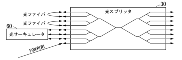
- the optical power supply system in the first modified embodiment described below (hereinafter referred to as "optical power supply system 1a") is configured such that, of the multiple unused terminals on the station side of the optical splitter 30, two unused terminals are grouped into a set, and the unused terminals in each set are connected to each other by optical fiber. This converts the direction of the upstream signal to a downstream signal, and the network path is folded back.
- FIG. 7 is a diagram showing the configuration of the return of the network path of the optical power supply system 1a in a first modified embodiment of the present invention.
- the optical splitter 30 in the first modified embodiment is a multi-input, multi-output optical coupler with multiple terminals on both the station side and the user premises side.
- the optical splitter 30 illustrated in FIG. 7 is an 8-to-8 input/output optical coupler with eight terminals on the station side and eight terminals on the user premises side.
- one of the terminals on the station side of the optical splitter 30 is connected to the light source 12 in the station.
- three sets of terminals, each set consisting of two terminals, are connected to each other by optical fiber.
- the remaining terminal on the station side of the optical splitter 30 remains an unused terminal.
- the optical fiber for folding back the network path is connected only to the unused terminal on the station side of the optical splitter 30, but this is not limited to the above.
- the optical fiber for folding back the network path may be connected only to the unused terminal on the user's premises side of the optical splitter 30.
- a folding back network path that converts downstream signals into upstream signals is configured.
- the optical fiber for folding back the network path may be installed on both the unused terminal on the station side of the optical splitter 30 and the unused terminal on the user's premises side.
- the optical power supply system 1 in the above-mentioned embodiment was configured such that an optical circulator 60 that converts an upstream signal into a downstream signal was connected to an unused terminal on the station side of the optical splitter 30. Also, the optical power supply system 1a in the first modified example of the above-mentioned embodiment was configured such that, of the multiple unused terminals on the station side of the optical splitter 30, two unused terminals were grouped into a set, and the unused terminals in each set were connected to each other by optical fiber.
- optical power supply system 1b combines a configuration in which the network path is folded back using an optical circulator 60 similar to that of the optical power supply system 1 in the above-mentioned embodiment, and a configuration in which the network path is folded back using an optical fiber similar to that of the first modified example of the above-mentioned embodiment.
- FIG. 8 is a diagram showing the configuration of the network path turn-back of the optical power supply system 1b in the second modified embodiment of the present invention.
- the optical splitter 30 in the second modified embodiment is a multi-input, multi-output optical coupler with multiple terminals on both the station side and the user premises side.
- the optical splitter 30 illustrated in FIG. 8 is an 8-to-8 input/output optical coupler with eight terminals on the station side and eight terminals on the user premises side.
- one of the terminals on the station side of the optical splitter 30 is connected to the light source 12 in the station. Also, three of the remaining seven terminals on the station side of the optical splitter 30 are connected to the optical circulator 60. Also, of the remaining four terminals on the station side of the optical splitter 30, two terminals form a set, and two sets of terminals are connected to each other by optical fibers.
- the optical circulator 60 by combining a configuration in which the optical circulator 60 is used to fold back the network path and a configuration in which the optical fiber is used to fold back the network path, even if the number of unused terminals is odd, the number of remaining unused terminals can be made even by connecting the odd number of unused terminals to the optical circulator 60.
- two unused terminals are treated as a set, and the unused terminals in each set are connected to each other, and the upstream signals output from all unused terminals are each converted into downstream signals, making it possible to use them for optical power supply to the power supply target devices in the power supply target area.
- a return network path using the optical circulator 60 and optical fiber is installed only on the central office side of the optical splitter 30, but this is not limited to the above.
- a return network path using the optical circulator 60 and optical fiber may be installed only on the user premises side of the optical splitter 30.
- a return network path using the optical circulator 60 and optical fiber may be installed on both the central office side and the user premises side of the optical splitter 30.
- optical splitter 30 used in the optical power supply system 1 in the above-mentioned embodiment, the optical power supply system 1a in the first modified example of the embodiment, and the optical power supply system 1b in the second modified example of the embodiment is an existing optical splitter (optical coupler) of a PON, but is not limited to this. It is also possible to use any existing splitter or coupler that has been introduced in the city.
- the optical power supply system 1 in the above-described embodiment the optical power supply system 1a in the first modified embodiment, and the optical power supply system 1b in the second modified embodiment, the unused terminals of the optical splitter (optical coupler) are used for optical power supply, but this is not limited to this.
- a method can be considered in which a branch end that is being used for a different purpose or in a different system is stopped from being used for that purpose or in that system, and instead switched to being used for optical power supply.
- the optical power supply system has an optical power supply unit, a bidirectional optical splitter with multiple inputs and multiple outputs, and a folding unit.
- the optical power supply system is optical power supply systems 1, 1a, and 1b in the embodiments
- the folding unit includes optical circulator 60 in the embodiments, or an optical fiber connecting two terminals on one side of optical splitter 30, and the optical power supply unit is optical power supply unit 2 in the embodiments.
- the optical power supply unit supplies the power obtained from the received optical signal to the power supply target device.
- the multi-input, multi-output bidirectional optical splitter transmits the first optical signal sent from the first light source to the second light source side and the optical power supply unit, and transmits the second optical signal sent from the second light source to the first light source side and the optical power supply unit.
- the first light source is the light source 12 in the embodiment
- the second light source is the ONU in each user's home in the embodiment
- the first optical signal is the optical signal sent from the light source 12 in the embodiment
- the second optical signal is the optical signal sent from the ONU in each user's home in the embodiment.
- the return unit converts the upstream and downstream directions of the optical signal output from the optical splitter using an optical fiber connecting two terminals on one side of the optical splitter, and re-inputs the optical signal into the optical splitter.
- the optical power supply unit outputs to the power supply target device a combination of power obtained from a first optical signal sent from a first light source and transmitted through an optical splitter, and power obtained from a second optical signal sent from a second light source, output to a return unit through an optical splitter, redirected, and then transmitted again through the optical splitter.
- the return unit is connected to at least one side of a bidirectional optical splitter.
- one side is the station side or the user home side in the embodiment.
- the return unit further includes an optical circulator that outputs an optical signal input to one port from the other port.
- the optical circulator is optical circulator 60 having the configuration shown in FIG. 5 in the embodiment.
- the optical power supply system described above further includes a receiving device that is installed on the second light source side and receives the first optical signal.
- the receiving device includes a filter that removes optical signals in the wavelength region used for the second optical signal.
- the device to be powered is an optical line terminal.
- At least one of the first light source and the second light source is a Fabry-Perot laser.
- a part of the configuration of the optical power supply systems 1, 1a and 1b in the above-mentioned embodiment may be realized by a computer.
- a program for realizing this function may be recorded on a computer-readable recording medium, and the program recorded on the recording medium may be read into a computer system and executed to realize the function.
- computer system here includes hardware such as an OS and peripheral devices.
- computer-readable recording medium refers to portable media such as flexible disks, optical magnetic disks, ROMs, and CD-ROMs, and storage devices such as hard disks built into a computer system.
- the term "computer-readable recording medium” may include a medium that dynamically holds a program for a short period of time, such as a communication line when a program is transmitted via a network such as the Internet or a communication line such as a telephone line, and a medium that holds a program for a certain period of time, such as a volatile memory inside a computer system that is a server or client in such a case.
- the above-mentioned program may be a program for realizing a part of the above-mentioned function, or may be a program that can realize the above-mentioned function in combination with a program already recorded in the computer system, or may be a program that is realized using a programmable logic device such as an FPGA (Field Programmable Gate Array).
- a programmable logic device such as an FPGA (Field Programmable Gate Array).
Landscapes
- Engineering & Computer Science (AREA)
- Physics & Mathematics (AREA)
- Optics & Photonics (AREA)
- Computer Networks & Wireless Communication (AREA)
- Power Engineering (AREA)
- Optical Communication System (AREA)
Priority Applications (2)
| Application Number | Priority Date | Filing Date | Title |
|---|---|---|---|
| JP2025527254A JPWO2024261851A1 (https=) | 2023-06-20 | 2023-06-20 | |
| PCT/JP2023/022742 WO2024261851A1 (ja) | 2023-06-20 | 2023-06-20 | 光給電システム及び光給電方法 |
Applications Claiming Priority (1)
| Application Number | Priority Date | Filing Date | Title |
|---|---|---|---|
| PCT/JP2023/022742 WO2024261851A1 (ja) | 2023-06-20 | 2023-06-20 | 光給電システム及び光給電方法 |
Publications (1)
| Publication Number | Publication Date |
|---|---|
| WO2024261851A1 true WO2024261851A1 (ja) | 2024-12-26 |
Family
ID=93935080
Family Applications (1)
| Application Number | Title | Priority Date | Filing Date |
|---|---|---|---|
| PCT/JP2023/022742 Ceased WO2024261851A1 (ja) | 2023-06-20 | 2023-06-20 | 光給電システム及び光給電方法 |
Country Status (2)
| Country | Link |
|---|---|
| JP (1) | JPWO2024261851A1 (https=) |
| WO (1) | WO2024261851A1 (https=) |
Citations (3)
| Publication number | Priority date | Publication date | Assignee | Title |
|---|---|---|---|---|
| JP2018064231A (ja) * | 2016-10-14 | 2018-04-19 | 日本電信電話株式会社 | 光通信システム及び給電方法 |
| JP2018174478A (ja) * | 2017-03-31 | 2018-11-08 | 東日本電信電話株式会社 | 光通話送受信器と光給電システム |
| WO2022130483A1 (ja) * | 2020-12-15 | 2022-06-23 | 日本電信電話株式会社 | 光給電システム、光給電方法及び受電光通信装置 |
-
2023
- 2023-06-20 JP JP2025527254A patent/JPWO2024261851A1/ja active Pending
- 2023-06-20 WO PCT/JP2023/022742 patent/WO2024261851A1/ja not_active Ceased
Patent Citations (3)
| Publication number | Priority date | Publication date | Assignee | Title |
|---|---|---|---|---|
| JP2018064231A (ja) * | 2016-10-14 | 2018-04-19 | 日本電信電話株式会社 | 光通信システム及び給電方法 |
| JP2018174478A (ja) * | 2017-03-31 | 2018-11-08 | 東日本電信電話株式会社 | 光通話送受信器と光給電システム |
| WO2022130483A1 (ja) * | 2020-12-15 | 2022-06-23 | 日本電信電話株式会社 | 光給電システム、光給電方法及び受電光通信装置 |
Also Published As
| Publication number | Publication date |
|---|---|
| JPWO2024261851A1 (https=) | 2024-12-26 |
Similar Documents
| Publication | Publication Date | Title |
|---|---|---|
| JP4775665B2 (ja) | 自己回復機能を有するリング型パッシブ光ネットワーク | |
| CN110998403A (zh) | 分光装置 | |
| KR102527242B1 (ko) | Ftth 기반 인터넷 서비스를 제공하는 광 접속 장치 및 방법 | |
| JP7414081B2 (ja) | 光通信システム及び制御方法 | |
| CN104270191B (zh) | 波分复用汇聚接入型双纤环光网络实现波长复用和互保护功能的系统与方法 | |
| US10992387B2 (en) | Port replicator | |
| WO2024261851A1 (ja) | 光給電システム及び光給電方法 | |
| CN119629520B (zh) | 一种局端设备多业务复用器 | |
| JP7833220B2 (ja) | 仮想回線型光交換ネットワークシステム及びその光スイッチ | |
| Zhou et al. | Light-hierarchy: The optimal structure for multicast routing in WDM mesh networks | |
| Hsieh et al. | All-optical multicast routing in sparse splitting WDM networks | |
| CN101459473A (zh) | 分光器、合光器和点到多点网络系统 | |
| WO2024261854A1 (ja) | 光給電システム、光クロージャ及び光給電方法 | |
| JP4626208B2 (ja) | 光ネットワーク | |
| Bannister et al. | An all-optical multifiber tree network | |
| Zhu et al. | Flexible PON systems enabling optical virtual private network and upstream channel upgrade | |
| CN120498552B (zh) | 光通信系统、方法及相关装置 | |
| EP3258649B1 (en) | Passive optical hub | |
| CN222147755U (zh) | 光网络单元直接通信装置 | |
| Kumari et al. | Flat ball topology basics multi‐transceivers 100 km/2.5 Tbps gigabit‐ethernet PON architecture for energy efficiency in data centers | |
| WO2024057651A1 (ja) | 光給電方法、光給電システム及び光給電装置 | |
| US20250379655A1 (en) | Enhanced optical network unit, passive optical network, and communication method | |
| US10236656B2 (en) | Shared optical pumps among multiple fiber channels | |
| CN118869079A (zh) | 光纤到房间 | |
| JP2007295507A (ja) | 光伝送システム及び光中継装置 |
Legal Events
| Date | Code | Title | Description |
|---|---|---|---|
| 121 | Ep: the epo has been informed by wipo that ep was designated in this application |
Ref document number: 23942289 Country of ref document: EP Kind code of ref document: A1 |
|
| ENP | Entry into the national phase |
Ref document number: 2025527254 Country of ref document: JP Kind code of ref document: A |
|
| NENP | Non-entry into the national phase |
Ref country code: DE |